WO2020115955A1 - 二次電池用正極構造体 - Google Patents
二次電池用正極構造体 Download PDFInfo
- Publication number
- WO2020115955A1 WO2020115955A1 PCT/JP2019/032602 JP2019032602W WO2020115955A1 WO 2020115955 A1 WO2020115955 A1 WO 2020115955A1 JP 2019032602 W JP2019032602 W JP 2019032602W WO 2020115955 A1 WO2020115955 A1 WO 2020115955A1
- Authority
- WO
- WIPO (PCT)
- Prior art keywords
- positive electrode
- electrode structure
- current collector
- nickel
- thickness
- Prior art date
- Legal status (The legal status is an assumption and is not a legal conclusion. Google has not performed a legal analysis and makes no representation as to the accuracy of the status listed.)
- Ceased
Links
Images

Classifications
-
- H—ELECTRICITY
- H01—ELECTRIC ELEMENTS
- H01M—PROCESSES OR MEANS, e.g. BATTERIES, FOR THE DIRECT CONVERSION OF CHEMICAL ENERGY INTO ELECTRICAL ENERGY
- H01M4/00—Electrodes
- H01M4/02—Electrodes composed of, or comprising, active material
- H01M4/64—Carriers or collectors
- H01M4/66—Selection of materials
- H01M4/661—Metal or alloys, e.g. alloy coatings
-
- H—ELECTRICITY
- H01—ELECTRIC ELEMENTS
- H01M—PROCESSES OR MEANS, e.g. BATTERIES, FOR THE DIRECT CONVERSION OF CHEMICAL ENERGY INTO ELECTRICAL ENERGY
- H01M4/00—Electrodes
- H01M4/02—Electrodes composed of, or comprising, active material
- H01M4/24—Electrodes for alkaline accumulators
- H01M4/32—Nickel oxide or hydroxide electrodes
-
- H—ELECTRICITY
- H01—ELECTRIC ELEMENTS
- H01M—PROCESSES OR MEANS, e.g. BATTERIES, FOR THE DIRECT CONVERSION OF CHEMICAL ENERGY INTO ELECTRICAL ENERGY
- H01M10/00—Secondary cells; Manufacture thereof
- H01M10/24—Alkaline accumulators
- H01M10/26—Selection of materials as electrolytes
-
- H—ELECTRICITY
- H01—ELECTRIC ELEMENTS
- H01M—PROCESSES OR MEANS, e.g. BATTERIES, FOR THE DIRECT CONVERSION OF CHEMICAL ENERGY INTO ELECTRICAL ENERGY
- H01M10/00—Secondary cells; Manufacture thereof
- H01M10/24—Alkaline accumulators
- H01M10/30—Nickel accumulators
-
- H—ELECTRICITY
- H01—ELECTRIC ELEMENTS
- H01M—PROCESSES OR MEANS, e.g. BATTERIES, FOR THE DIRECT CONVERSION OF CHEMICAL ENERGY INTO ELECTRICAL ENERGY
- H01M4/00—Electrodes
- H01M4/02—Electrodes composed of, or comprising, active material
- H01M4/04—Processes of manufacture in general
- H01M4/043—Processes of manufacture in general involving compressing or compaction
-
- H—ELECTRICITY
- H01—ELECTRIC ELEMENTS
- H01M—PROCESSES OR MEANS, e.g. BATTERIES, FOR THE DIRECT CONVERSION OF CHEMICAL ENERGY INTO ELECTRICAL ENERGY
- H01M4/00—Electrodes
- H01M4/02—Electrodes composed of, or comprising, active material
- H01M4/24—Electrodes for alkaline accumulators
- H01M4/244—Zinc electrodes
-
- H—ELECTRICITY
- H01—ELECTRIC ELEMENTS
- H01M—PROCESSES OR MEANS, e.g. BATTERIES, FOR THE DIRECT CONVERSION OF CHEMICAL ENERGY INTO ELECTRICAL ENERGY
- H01M4/00—Electrodes
- H01M4/02—Electrodes composed of, or comprising, active material
- H01M4/36—Selection of substances as active materials, active masses, active liquids
- H01M4/48—Selection of substances as active materials, active masses, active liquids of inorganic oxides or hydroxides
- H01M4/52—Selection of substances as active materials, active masses, active liquids of inorganic oxides or hydroxides of nickel, cobalt or iron
-
- H—ELECTRICITY
- H01—ELECTRIC ELEMENTS
- H01M—PROCESSES OR MEANS, e.g. BATTERIES, FOR THE DIRECT CONVERSION OF CHEMICAL ENERGY INTO ELECTRICAL ENERGY
- H01M4/00—Electrodes
- H01M4/02—Electrodes composed of, or comprising, active material
- H01M4/64—Carriers or collectors
- H01M4/66—Selection of materials
- H01M4/668—Composites of electroconductive material and synthetic resins
-
- H—ELECTRICITY
- H01—ELECTRIC ELEMENTS
- H01M—PROCESSES OR MEANS, e.g. BATTERIES, FOR THE DIRECT CONVERSION OF CHEMICAL ENERGY INTO ELECTRICAL ENERGY
- H01M4/00—Electrodes
- H01M4/02—Electrodes composed of, or comprising, active material
- H01M4/64—Carriers or collectors
- H01M4/70—Carriers or collectors characterised by shape or form
- H01M4/80—Porous plates, e.g. sintered carriers
- H01M4/808—Foamed, spongy materials
-
- H—ELECTRICITY
- H01—ELECTRIC ELEMENTS
- H01M—PROCESSES OR MEANS, e.g. BATTERIES, FOR THE DIRECT CONVERSION OF CHEMICAL ENERGY INTO ELECTRICAL ENERGY
- H01M50/00—Constructional details or processes of manufacture of the non-active parts of electrochemical cells other than fuel cells, e.g. hybrid cells
- H01M50/40—Separators; Membranes; Diaphragms; Spacing elements inside cells
- H01M50/409—Separators, membranes or diaphragms characterised by the material
- H01M50/411—Organic material
- H01M50/414—Synthetic resins, e.g. thermoplastics or thermosetting resins
- H01M50/417—Polyolefins
-
- H—ELECTRICITY
- H01—ELECTRIC ELEMENTS
- H01M—PROCESSES OR MEANS, e.g. BATTERIES, FOR THE DIRECT CONVERSION OF CHEMICAL ENERGY INTO ELECTRICAL ENERGY
- H01M50/00—Constructional details or processes of manufacture of the non-active parts of electrochemical cells other than fuel cells, e.g. hybrid cells
- H01M50/40—Separators; Membranes; Diaphragms; Spacing elements inside cells
- H01M50/409—Separators, membranes or diaphragms characterised by the material
- H01M50/431—Inorganic material
- H01M50/434—Ceramics
-
- H—ELECTRICITY
- H01—ELECTRIC ELEMENTS
- H01M—PROCESSES OR MEANS, e.g. BATTERIES, FOR THE DIRECT CONVERSION OF CHEMICAL ENERGY INTO ELECTRICAL ENERGY
- H01M50/00—Constructional details or processes of manufacture of the non-active parts of electrochemical cells other than fuel cells, e.g. hybrid cells
- H01M50/40—Separators; Membranes; Diaphragms; Spacing elements inside cells
- H01M50/409—Separators, membranes or diaphragms characterised by the material
- H01M50/44—Fibrous material
-
- H—ELECTRICITY
- H01—ELECTRIC ELEMENTS
- H01M—PROCESSES OR MEANS, e.g. BATTERIES, FOR THE DIRECT CONVERSION OF CHEMICAL ENERGY INTO ELECTRICAL ENERGY
- H01M50/00—Constructional details or processes of manufacture of the non-active parts of electrochemical cells other than fuel cells, e.g. hybrid cells
- H01M50/40—Separators; Membranes; Diaphragms; Spacing elements inside cells
- H01M50/409—Separators, membranes or diaphragms characterised by the material
- H01M50/446—Composite material consisting of a mixture of organic and inorganic materials
-
- H—ELECTRICITY
- H01—ELECTRIC ELEMENTS
- H01M—PROCESSES OR MEANS, e.g. BATTERIES, FOR THE DIRECT CONVERSION OF CHEMICAL ENERGY INTO ELECTRICAL ENERGY
- H01M50/00—Constructional details or processes of manufacture of the non-active parts of electrochemical cells other than fuel cells, e.g. hybrid cells
- H01M50/40—Separators; Membranes; Diaphragms; Spacing elements inside cells
- H01M50/46—Separators, membranes or diaphragms characterised by their combination with electrodes
-
- H—ELECTRICITY
- H01—ELECTRIC ELEMENTS
- H01M—PROCESSES OR MEANS, e.g. BATTERIES, FOR THE DIRECT CONVERSION OF CHEMICAL ENERGY INTO ELECTRICAL ENERGY
- H01M50/00—Constructional details or processes of manufacture of the non-active parts of electrochemical cells other than fuel cells, e.g. hybrid cells
- H01M50/40—Separators; Membranes; Diaphragms; Spacing elements inside cells
- H01M50/471—Spacing elements inside cells other than separators, membranes or diaphragms; Manufacturing processes thereof
- H01M50/474—Spacing elements inside cells other than separators, membranes or diaphragms; Manufacturing processes thereof characterised by their position inside the cells
-
- H—ELECTRICITY
- H01—ELECTRIC ELEMENTS
- H01M—PROCESSES OR MEANS, e.g. BATTERIES, FOR THE DIRECT CONVERSION OF CHEMICAL ENERGY INTO ELECTRICAL ENERGY
- H01M50/00—Constructional details or processes of manufacture of the non-active parts of electrochemical cells other than fuel cells, e.g. hybrid cells
- H01M50/40—Separators; Membranes; Diaphragms; Spacing elements inside cells
- H01M50/471—Spacing elements inside cells other than separators, membranes or diaphragms; Manufacturing processes thereof
- H01M50/48—Spacing elements inside cells other than separators, membranes or diaphragms; Manufacturing processes thereof characterised by the material
- H01M50/486—Organic material
-
- H—ELECTRICITY
- H01—ELECTRIC ELEMENTS
- H01M—PROCESSES OR MEANS, e.g. BATTERIES, FOR THE DIRECT CONVERSION OF CHEMICAL ENERGY INTO ELECTRICAL ENERGY
- H01M50/00—Constructional details or processes of manufacture of the non-active parts of electrochemical cells other than fuel cells, e.g. hybrid cells
- H01M50/40—Separators; Membranes; Diaphragms; Spacing elements inside cells
- H01M50/489—Separators, membranes, diaphragms or spacing elements inside the cells, characterised by their physical properties, e.g. swelling degree, hydrophilicity or shut down properties
- H01M50/497—Ionic conductivity
-
- H—ELECTRICITY
- H01—ELECTRIC ELEMENTS
- H01M—PROCESSES OR MEANS, e.g. BATTERIES, FOR THE DIRECT CONVERSION OF CHEMICAL ENERGY INTO ELECTRICAL ENERGY
- H01M4/00—Electrodes
- H01M4/02—Electrodes composed of, or comprising, active material
- H01M2004/021—Physical characteristics, e.g. porosity, surface area
-
- H—ELECTRICITY
- H01—ELECTRIC ELEMENTS
- H01M—PROCESSES OR MEANS, e.g. BATTERIES, FOR THE DIRECT CONVERSION OF CHEMICAL ENERGY INTO ELECTRICAL ENERGY
- H01M4/00—Electrodes
- H01M4/02—Electrodes composed of, or comprising, active material
- H01M2004/026—Electrodes composed of, or comprising, active material characterised by the polarity
- H01M2004/028—Positive electrodes
-
- H—ELECTRICITY
- H01—ELECTRIC ELEMENTS
- H01M—PROCESSES OR MEANS, e.g. BATTERIES, FOR THE DIRECT CONVERSION OF CHEMICAL ENERGY INTO ELECTRICAL ENERGY
- H01M2300/00—Electrolytes
- H01M2300/0017—Non-aqueous electrolytes
- H01M2300/0065—Solid electrolytes
- H01M2300/0068—Solid electrolytes inorganic
-
- Y—GENERAL TAGGING OF NEW TECHNOLOGICAL DEVELOPMENTS; GENERAL TAGGING OF CROSS-SECTIONAL TECHNOLOGIES SPANNING OVER SEVERAL SECTIONS OF THE IPC; TECHNICAL SUBJECTS COVERED BY FORMER USPC CROSS-REFERENCE ART COLLECTIONS [XRACs] AND DIGESTS
- Y02—TECHNOLOGIES OR APPLICATIONS FOR MITIGATION OR ADAPTATION AGAINST CLIMATE CHANGE
- Y02E—REDUCTION OF GREENHOUSE GAS [GHG] EMISSIONS, RELATED TO ENERGY GENERATION, TRANSMISSION OR DISTRIBUTION
- Y02E60/00—Enabling technologies; Technologies with a potential or indirect contribution to GHG emissions mitigation
- Y02E60/10—Energy storage using batteries
Definitions
- the present invention relates to a positive electrode structure for a secondary battery.
- the laminated battery has a structure in which a laminated body in which a plurality of unit cells are connected in series or in parallel is housed in one battery container.
- Patent Document 1 International Publication No. WO 2017/086278 discloses a zinc secondary battery in which a plurality of electrode cartridges each including an electrode and a separator (especially an LDH separator described later) are housed in a sealed container. There is.
- a positive electrode plate, a separator and a negative electrode plate are housed in a closed container in an upright state, and a nonwoven fabric is provided between the positive electrode plate and the separator and/or between the negative electrode plate and the separator. Is provided.
- a non-woven fabric in this manner, since it can exhibit various functions such as a cushioning material, a liquid retaining material, a fall-preventing material, and a bubble escape material, it is possible to prevent the constituent particles from falling off from the positive electrode plate or the negative electrode plate, The electrolyte can be sufficiently brought into contact with and retained by the separator while escaping bubbles that may be generated, and/or the hydroxide ion conductivity of the separator can be maximized.
- Patent Document 4 International Publication No. 2016/076047 discloses a separator structure including an LDH separator fitted or joined to a resin outer frame, and the LDH separator has gas impermeability and It is disclosed to have a high degree of compaction such that it has water/impermeable properties. This document also discloses that the LDH separator can be composited with a porous substrate.
- Patent Document 5 International Publication No. 2016/067884 discloses various methods for forming a LDH dense film on the surface of a porous substrate to obtain a composite material (LDH separator).
- a starting material that can give a starting point of LDH crystal growth is uniformly attached to a porous substrate, and the porous substrate is hydrothermally treated in a raw material aqueous solution to form an LDH dense film on the surface of the porous substrate. It includes a step of forming.
- nickel-metal hydride batteries and nickel-zinc batteries use foamed nickel as a positive electrode current collector (for example, Patent Document 1).
- Foamed nickel is a porous metal body having an open pore structure made of nickel. Since the positive electrode active material (nickel hydroxide) does not have electric conductivity, foamed nickel having a three-dimensional structure is used as the positive electrode current collector.
- a current collector terminal will be joined to the foamed nickel, but it is desirable to perform the joining by ultrasonic welding from the viewpoint of improving productivity.
- ultrasonic welding there is a problem that the foamed nickel is broken and cannot be welded well.
- the inventors of the present invention have determined that the foamed nickel that constitutes the uncoated portion in which the positive electrode active material is not present has a predetermined thickness with respect to the thickness of the nickel foam that constitutes the coated portion in which the positive electrode active material is incorporated.
- the present inventors have found that it is possible to join the foamed nickel and the current collector terminal by ultrasonic welding by adopting a configuration in which the ratio is compressed.
- an object of the present invention is to provide a positive electrode structure provided with a foamed nickel current collector in a state capable of ultrasonic welding with a current collection terminal.
- a positive electrode structure for a secondary battery A positive electrode current collector composed of flat-plate foamed nickel and having a flat-plate coated portion and an uncoated portion extending from the outer peripheral portion of the coated portion, A positive electrode active material containing nickel hydroxide and/or nickel oxyhydroxide, which is incorporated in the coating part of the positive electrode current collector, Equipped with The positive electrode active material does not exist in the uncoated portion of the positive electrode current collector, The positive electrode structure in which the foamed nickel forming the uncoated portion is compressed to a thickness of 0.10 times or more and less than 0.8 times the thickness of the foamed nickel forming the coated portion.
- the body is provided.
- the positive electrode structure A negative electrode structure including a negative electrode active material layer containing at least one selected from the group consisting of zinc, zinc oxide, a zinc alloy, and a zinc compound, A porous substrate made of a polymeric material, and an LDH separator comprising a layered double hydroxide (LDH) that closes the pores of the porous substrate so as to exhibit hydroxide ion conductivity and gas impermeability; Electrolyte and A nickel-zinc secondary battery including the positive electrode and the negative electrode active material layer is isolated from each other via the LDH separator.
- LDH layered double hydroxide
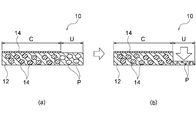
- FIG. 1 is a cross-sectional view conceptually showing a positive electrode structure according to an aspect of the present invention, in which (a) shows a state before compressing nickel foam of an uncoated portion, and (b) shows nickel foam of an uncoated portion. The state after compression is shown.
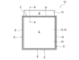
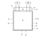
- 1 is a front view showing a positive electrode structure according to an aspect of the present invention.
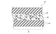
- FIG. 3 is a cross-sectional view schematically showing a non-woven fabric/positive electrode current collector/nonwoven fabric heat-sealing sealing structure at a sealing side S′ of the positive electrode structure shown in FIG. 2. It is sectional drawing which shows typically the laminated body before heat-sealing the nonwoven fabric in the production of the positive electrode structure shown in FIG. FIG.
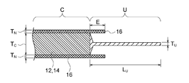
- FIG. 6 is a cross-sectional view of the positive electrode structure shown in FIG. 2 taken along the line AA, corresponding to the positive electrode structure that has been heat-sealed with the laminate shown in FIG. 4. It is a front view which shows the positive electrode structure in which only the outer periphery 3 side S of the nonwoven fabric was sealed.
- the positive electrode structure of the present invention is used in a secondary battery such as a nickel hydrogen battery or a nickel zinc battery, preferably a nickel zinc secondary battery.
- FIG. 1 shows an example of the positive electrode structure of the present invention.
- the positive electrode structure 10 shown in FIG. 1 includes a positive electrode current collector 12 and a positive electrode active material 14.
- the positive electrode current collector 12 is made of flat-plate nickel foam, and has a flat-plate coated portion C and an uncoated portion U extending from the outer peripheral portion of the coated portion C.
- the positive electrode active material 14 contains nickel hydroxide and/or nickel oxyhydroxide, and is incorporated in the coating part C of the positive electrode current collector 12.
- the positive electrode active material 14 does not exist in the uncoated portion U of the positive electrode current collector 12.
- the nickel foam forming the uncoated portion U is compressed to a thickness of 0.10 times or more and less than 0.8 times the thickness of the nickel foam forming the coated portion C. That is, as shown in FIG. 1(a), the nickel foam is initially a member having a substantially constant thickness over the entire area from the coated portion C to the uncoated portion U, but the arrow shown in FIG. The thickness is reduced by being compressed in the direction. In this way, the nickel foam forming the uncoated portion U is compressed to a predetermined ratio with respect to the thickness of the nickel foam forming the coated portion C, thereby collecting the nickel foam and nickel. It is possible to join the electrical terminals by ultrasonic welding.
- the ratio of the pores P for example, the number of pores and the pore size
- the ratio of the pores P is reduced by compressing the uncoated portion U, and a form close to a metal plate suitable for ultrasonic welding is realized. It is conceivable that.
- the pores P can be left without being completely removed to allow sealing and bonding with a non-woven fabric by heat welding or the like.
- the positive electrode current collector 12 is made of foamed nickel.
- Foamed nickel is a porous metal body having an open pore structure made of nickel.
- the foamed nickel has a flat plate shape, preferably a rectangular shape (for example, a quadrilateral shape), for use as the positive electrode current collector 12.
- the term "flat plate” does not have to be a completely flat shape, and as long as the outline of a flat plate is generally recognized, a change in thickness such as a step or waviness (for example, the coating portion C and A step or a tapered thickness change at the boundary of the uncoated portion U) is allowed.
- the term “rectangular shape” to “quadrilateral shape” does not need to be a complete rectangular shape or quadrilateral shape, and as long as a generally rectangular or quadrilateral outer shape is recognized, a notch, a rounded corner, or the like. There may be some deformation of.
- Commercially available nickel foam may be used as the positive electrode current collector 12, and examples thereof include Celmet (registered trademark) manufactured by Sumitomo Electric Industries, Ltd. Foamed nickel having various specifications is commercially available, and the thickness, the average pore diameter, the average window diameter, etc. may be appropriately selected according to the desired thickness and performance.
- nickel foam having a thickness of 0.5 to 10 mm, an average pore diameter of 0.3 to 5 mm, and an average window diameter of 0.2 to 2 mm can be preferably used.
- the thickness, the average pore diameter, and the average window diameter are not the numerical values in the positive electrode structure 10 as the final form because they change depending on the filling of the positive electrode active material 14 and the subsequent pressing.
- the nickel foam forming the uncoated portion U has a thickness of 0.10 times or more and less than 0.8 times, preferably 0.11 times or more and 0.5 times the thickness of the nickel foam forming the coated portion C. It is compressed to a thickness of less than 0.13 times, more preferably 0.13 times or more and less than 0.3 times. Within this range, the foamed nickel and the current collector terminal can be joined well by ultrasonic welding, and thermal welding to the non-woven fabric is also facilitated.
- the compression of the nickel foam forming the uncoated portion U is preferably performed by pressing with a uniaxial press, a roll press, or the like to adjust the thickness to a desired thickness.
- the thickness of the nickel foam forming the uncoated portion U is preferably 0.10 to 0.30 mm, more preferably 0.10 to 0.25 mm, and further preferably 0. 10 to 0.20 mm.
- the positive electrode current collector 12 has a flat coated portion C and an uncoated portion U extending from the outer peripheral portion (typically one side) of the coated portion C.
- the coated portion C is a portion where the positive electrode active material 14 is incorporated, and the uncoated portion U is a portion where the positive electrode active material 14 is left unincorporated. Therefore, in the positive electrode structure 10, the positive electrode active material does not exist in the uncoated portion U of the positive electrode current collector 12. Therefore, the uncoated portion U of the positive electrode current collector 12 is suitable for connecting the positive electrode terminal by ultrasonic welding or the like.
- the extension distance of the uncoated portion U from the coated portion C is preferably 5 to 50 mm, more preferably 5 to 40 mm, and further preferably 5 to 30 mm.
- the positive electrode active material 14 contains nickel hydroxide and/or nickel oxyhydroxide. Therefore, the secondary battery of the present invention is particularly suitable for a nickel zinc secondary battery.
- the coated portion C of the positive electrode current collector 12 can be filled with the positive electrode active material 14 as follows.
- a positive electrode active material paste containing an active material powder containing nickel hydroxide as a main component, a binder and the like is filled in the holes of the coated portion C of the positive electrode current collector 12 and dried.
- the coated portion C filled with the positive electrode active material paste is sufficiently dried, and then uniformly pressed by a roll press to adjust it to a desired thickness.
- a roll press By pressing the coated portion C after drying, it is possible to prevent the electrode active material from falling off and improve the electrode density. It is preferable to appropriately adjust the paste preparation conditions and the roll press conditions so that a desired density can be obtained.
- the thickness (that is, T C in FIG. 5) of the positive electrode current collector 12 incorporating the positive electrode active material 14 is preferably 0.2 to 2.0 mm, more preferably 0.4 to 1.4 mm. Yes, and more preferably 0.6 to 0.8 mm.
- “the thickness of the positive electrode current collector 12 in which the positive electrode active material 14 is incorporated” means not only the thickness of the positive electrode current collector 12 including the positive electrode active material 14 therein but also the positive electrode current collector 12.
- the total thickness of the positive electrode plate composed of the positive electrode active material 14 and the positive electrode current collector 12, including the thickness of the positive electrode active material 14 attached to the surface of the body 12, is meant.
- the positive electrode structure 10 may further include a nonwoven fabric 16.
- the nonwoven fabric 16 is made of a polymer material and covers the coated portion C of the positive electrode current collector 12 from both sides. More preferably, the nonwoven fabric 16 includes the entire coated portion C and extends from the outer peripheral portion of the coated portion C to form a surplus region E, and the outer peripheral portion of the coated portion C is entirely covered. The surplus area E is sealed so as to be closed over the circumference. In this way, the coated portion C of the positive electrode current collector 12 in which the positive electrode active material 14 is incorporated is covered with the nonwoven fabric 16 from both sides, and the outer peripheral portion of the coated portion C is closed over the entire circumference thereof.
- the positive electrode structure 10 capable of suppressing a self-discharge reaction and obtaining a target voltage when incorporated in a secondary battery. That is, in providing the non-woven fabric on the positive electrode plate, in order to effectively obtain various functions of the non-woven fabric (functions such as a cushioning material, a liquid retaining material, a fall-preventing material, and a bubble escape material), the non-woven fabric is used to sandwich the positive electrode plate from both sides. It is conceivable to seal the end portions of each other by heat welding or the like. In this case, in order to avoid interference with the current collector, as shown in FIG.
- the battery reaches the negative electrode to form a local battery, and the self-discharge reaction of the negative electrode occurs, so that a target voltage cannot be obtained. Therefore, using foamed nickel as the positive electrode current collector 12, the non-woven fabric 16 is extended from the outer peripheral portion of the coating portion C to form the excess region E, and as shown in FIG. The non-woven fabric 16 is sealed together with the positive electrode current collector 12.
- a normal positive electrode current collector made of a non-porous metal plate cannot be heat-welded by sandwiching it with a non-woven fabric, but by adopting foamed nickel, as shown in FIG.
- the nonwoven fabrics 16 can be heat-welded to each other in the voids in the positive electrode current collector 12 when the nonwoven fabric 16 is melted, and effective sealing is realized.
- a sealing method other than heat welding such as an adhesive or ultrasonic welding is used, similar sealing can be achieved by utilizing the large number of voids.
- the side S of the non-woven fabric 16 that does not overlap with the positive electrode current collector 12 but also the side S′ of the non-woven fabric 16 that overlaps with the positive electrode current collector 12 is sealed, so that the nickel component and the like dropped from the positive electrode is exposed to the outside.
- the desired voltage can be obtained by suppressing the self-discharge reaction without diffusion.
- the non-woven fabric 16 is preferably a non-woven fabric made of a polymer material.
- the non-woven fabric 16 effectively provides various functions of the non-woven fabric (functions such as a cushioning material, a liquid retaining material, a fall prevention material, and a bubble escape material) by covering the coated portion C of the positive electrode current collector 12 from both sides. You can That is, since the non-woven fabric can exhibit various functions such as a cushioning material, a liquid retaining material, a fall prevention material, and a bubble escape material, it is possible to prevent the constituent particles from falling off from the positive electrode and/or to generate bubbles.
- the electrolyte solution can be sufficiently brought into contact with and held by the positive electrode active material 14 and the separator while being released.
- the polymer material forming the nonwoven fabric is preferably a thermoplastic polymer material from the viewpoint of performing heat-sealing.
- the thermoplastic polymer material include polyethylene, polypropylene, polyester and the like, and particularly preferably polyethylene and/or polypropylene.
- the thickness of the non-woven fabric 16 is preferably 0.05 to 0.2 mm, more preferably from the viewpoint of the various functions (particularly the liquid retaining property) of the non-woven fabric described above and the ease of sealing (particularly heat fusion sealing). Is 0.07 to 0.15 mm, and more preferably 0.08 to 0.10 mm.
- the non-woven fabric 16 may be a commercially available one, and the basis weight and thickness may be appropriately selected in consideration of the water absorption rate, the water retention property and the like so that desired characteristics can be obtained.
- the non-woven fabric 16 is preferably one having hydrophilicity imparted by a surfactant or plasma treatment.
- the nonwoven fabric 16 includes the entire coated portion C and extends from the outer peripheral portion of the coated portion C to form a surplus region E.
- the surplus area E is sealed so as to close the part over the entire circumference.
- the non-woven fabric 16 is sealed with the positive electrode current collector 12 sandwiched in a portion of the surplus region E that overlaps the uncoated portion U.
- the width W of the portion where the nonwoven fabric 16 is sealed with the positive electrode current collector 12 sandwiched is preferably 1 to 10 mm, more preferably 1 to 7 mm, and further preferably 1 to 4 mm. is there.
- the thickness T S of the portion where the nonwoven fabric 16 is sealed with the positive electrode current collector 12 sandwiched is preferably 0.1 to 1.0 mm, and more preferably 0.1 to 0.7 mm. , And more preferably 0.1 to 0.4 mm. As shown in FIG.
- the inside of the pores of the nickel foam forming the positive electrode current collector 12 is made of the polymer material ( That is, it is preferably filled with the polymer material in a melted and solid state derived from the nonwoven fabric 16.
- the positive electrode structure 10 includes a positive electrode collector C and a portion (side S′) where the nonwoven fabric 16 is sealed with the positive electrode collector 12 sandwiched therebetween. It is preferable that the pores of the nickel foam forming the electric body 12 have an unfilled region F that is not filled with the above-described polymer material (that is, the constituent material of the nonwoven fabric 16) or the positive electrode active material.
- the non-filled region F functions as a buffer for sufficiently separating the coated portion C from the portion (side S′) in which the non-woven fabric 16 is sealed with the positive electrode current collector 12 sandwiched therebetween. It is possible to effectively prevent the positive electrode active material 14 from penetrating into the above-mentioned sealed portion from the above, and to more securely seal the nonwoven fabric 16 via the positive electrode current collector 12. Further, since there is the non-filled area F, it is possible to avoid contact with the coated portion C when pressing the uncoated portion U.
- the positive electrode structure 10 has a tapered shape in which the thickness decreases from the coated portion C toward the uncoated portion in a portion of the surplus region E that overlaps with the uncoated portion U. It is preferable to have a cross-sectional shape of With such a cross-sectional shape, when the nickel foam is pressed (that is, when the uncoated portion U is pressed), the nickel foam is damaged due to a sudden change in thickness at the boundary between the coated portion C and the uncoated portion U, and It is possible to effectively prevent breakage of the nonwoven fabric 16 at the boundary between the coated portion C and the uncoated portion U when the nonwoven fabric 16 is sealed.
- the non-woven fabric 16 be sealed without sandwiching the positive electrode current collector 12 in a portion (side S) of the surplus region E that does not overlap the uncoated portion U. Since the non-woven fabrics 16 can be directly sealed without interposing the positive electrode current collector 12, the sealing becomes easy.
- the nickel foam has a rectangular shape (for example, a quadrilateral shape), and the nonwoven fabric 16 includes the entire coated portion C and the coated portion.
- a surplus region E is formed by extending from the outer periphery 4 sides of C, and the surplus region E is sealed so as to close the outer periphery 4 sides S, S′ of the coating portion C.
- the sealing in the surplus area E can be performed by a known method such as an adhesive, heat welding, ultrasonic welding, adhesive tape, sealing tape, etc., but preferably heat welding sealing.
- the heat-sealing can be simply performed using a commercially available heat-sealing bar, and as described above with reference to FIG. 3, the positive electrode current collector 12 is covered with the nonwoven fabric 16 from both sides of the positive electrode current collector 12. It is advantageous to seal the whole. That is, when the non-woven fabric 16 is melted, the non-woven fabrics 16 can be thermally welded to each other in the voids in the positive electrode current collector 12, and effective sealing can be realized.
- the heat-sealing of the nonwoven fabric 16 is performed by sandwiching the coated portion C from both sides with the nonwoven fabric 16 cut into a size larger than the coated portion C (see, for example, FIG. 4), and coating the end portion of the nonwoven fabric 16.
- the surplus area E protruding from C may be thermocompression-bonded with a heat seal bar or the like (see, for example, FIG. 5).
- the thermocompression bonding is preferably performed by pressing at a heating temperature of 150 to 200° C. for 1 second or longer.
- the positive electrode structure 10 of the present invention is preferably used in a nickel zinc secondary battery.
- the nickel-zinc secondary battery includes the positive electrode structure 10, the negative electrode structure, the LDH separator, and the electrolytic solution described above, and the positive electrode and the negative electrode active material layer are isolated from each other via the LDH separator.
- the negative electrode structure includes a negative electrode active material layer containing at least one selected from the group consisting of zinc, zinc oxide, a zinc alloy, and a zinc compound, and optionally further includes a negative electrode current collector.
- the negative electrode active material include zinc oxide, zinc metal, calcium zincate and the like, but a mixture of zinc metal and zinc oxide is more preferable.
- the electrolytic solution preferably contains an aqueous alkali metal hydroxide solution.
- alkali metal hydroxide examples include potassium hydroxide, sodium hydroxide, lithium hydroxide, ammonium hydroxide and the like, and potassium hydroxide is more preferable.
- An LDH separator is a separator containing layered double hydroxide (LDH), and is defined as one that selectively utilizes the hydroxide ion conductivity of LDH to selectively pass hydroxide ions.
- a preferred LDH separator comprises LDH and a porous substrate. As described above, the LDH separator may have pores in the porous substrate so that the LDH separator exhibits hydroxide ion conductivity and gas impermeability (and thus functions as an LDH separator exhibiting hydroxide ion conductivity). It is blocking.
- the porous substrate is preferably made of a polymeric material, and LDH is particularly preferably incorporated throughout the thickness of the polymeric porous substrate. For example, known LDH separators disclosed in Patent Documents 2 to 4 can be used.
- the unit cell element including the positive electrode structure 10, the negative electrode structure, the LDH separator, and the electrolytic solution is housed in a sealed container and can be functioned as a main component of the sealed zinc secondary battery by being closed by the lid. .. More preferably, a plurality of unit cell elements are housed in the closed container to form an assembled battery.
- Example 1 Preparation of positive electrode structure A positive electrode paste was prepared by mixing a positive electrode active material powder containing nickel hydroxide as a main component with a binder.
- a positive electrode current collector As the positive electrode current collector, a rectangular flat-plate foamed nickel (Sumitomo Electric Industries, Ltd., Celmet (registered trademark), product number #7, thickness 1.6 mm, average hole diameter 0.51 mm, average window diameter 0.23 m) was prepared. Then, the positive electrode paste was filled in the holes of the portion to be the nickel foam coating portion and dried. At this time, the portion of the nickel foam to be the uncoated portion was masked in advance to close the hole, so that the positive electrode paste did not enter the hole of the uncoated portion.
- foamed nickel (positive electrode current collector) partially filled with the positive electrode active material was obtained as a positive electrode plate.
- the obtained positive electrode plate was sufficiently dried and then uniformly pressed by a roll press to reduce the thickness of the coated portion to 0.70 mm.
- the uncoated portion of nickel foam (the portion not filled with the positive electrode active material) was also compressed to some extent, but the hydraulic pressure was 0.1 MPa and the gap was 0.06 mm in order to selectively further compress the uncoated portion U.
- the thickness of the uncoated portion was reduced to 0.10 mm by applying a roll press under the conditions of. That is, the nickel foam forming the uncoated portion was compressed to a thickness 0.14 times the thickness of the nickel foam forming the coated portion.
- Uncoated portion length L U i.e. protruding length from the coated portion C
- Uncoated portion length L U i.e. protruding length from the coated portion C
- a commercially available non-woven fabric (manufactured by Nippon Vilene Co., Ltd., material: polypropylene, thickness: 0.10 mm, unit area weight: 40 g/m 2 ) was cut into a rectangular shape having a size larger than the coating portion C. As shown in FIG. 4, the coated portion C was sandwiched and covered with the obtained rectangular nonwoven fabric 16 as shown in FIG. At this time, the non-woven fabric 16 included the entire coated portion C and extended from the outer four sides of the coated portion C to form a surplus region. The surplus region E was heat-welded and sealed (thermocompression bonding) so as to close all four sides of the coated portion C.
- This heat-sealing was performed by heating the end portion of the nonwoven fabric 16 at a temperature of 150 to 200° C. for 1 second or longer using a commercially available heat seal bar.
- the nonwoven fabrics 16 were directly heat-sealed together without sandwiching the positive electrode current collector 12.
- the positive electrode current collector 12 was sandwiched by the nonwoven fabric 16 from both sides and heat-sealed.
- the positive electrode structure 10 as shown in FIG. 5 was obtained.
- -Negative electrode structure Copper expanded metal, to which a negative electrode active material layer containing metallic zinc and zinc oxide powder together with a binder is pressure-bonded and covered with a non-woven fabric-LDH separator: Porous base material made of polymer material (polyethylene) Separator pressed with LDH so that its pores exhibit hydroxide ion conductivity and gas impermeability
- the nickel-zinc secondary battery thus manufactured was subjected to the following liquid injection process, chemical conversion process and waste liquid process as a chemical conversion process.
- -Filling step The electrolyte solution (5.4 mol% potassium hydroxide aqueous solution) was permeated into the positive electrode structure and the negative electrode structure. The amount of the electrolytic solution was set such that the entire laminate was immersed, and the total amount was divided into two portions to be used for dipping under reduced pressure (-90 kPa) and dipping under open air.
- -Chemical conversion step As a treatment for activation of the positive electrode, charging and discharging were performed to respective depths of 80%, 100% and 120% of the positive electrode mounting capacity.
- -Drainage step After the chemical conversion step, the excess electrolytic solution that was not absorbed by the positive electrode structure and the negative electrode structure was inverted by 180° from the battery and discharged from the injection port.
- Example 2 As shown in FIG. 6, the surplus area E was heat-welded and sealed (thermocompression bonding) so as to close only three sides S of the four outer sides of the coated section C (that is, the uncoated section of the surplus area E).
- a positive electrode structure was prepared and evaluated in the same manner as in Example 1 except that the heat-sealing was not performed in the portion overlapping with (the side O).
Landscapes
- Chemical & Material Sciences (AREA)
- Chemical Kinetics & Catalysis (AREA)
- Electrochemistry (AREA)
- General Chemical & Material Sciences (AREA)
- Engineering & Computer Science (AREA)
- Inorganic Chemistry (AREA)
- Materials Engineering (AREA)
- Composite Materials (AREA)
- Manufacturing & Machinery (AREA)
- Ceramic Engineering (AREA)
- Cell Electrode Carriers And Collectors (AREA)
- Battery Electrode And Active Subsutance (AREA)
- Cell Separators (AREA)
- Secondary Cells (AREA)
Abstract
Description
平板状の発泡ニッケルで構成され、平板状の塗工部及び該塗工部の外周部から延在する未塗工部を有する、正極集電体と、
前記正極集電体の前記塗工部に組み込まれる、水酸化ニッケル及び/又はオキシ水酸化ニッケルを含む正極活物質と、
を備え、
前記正極集電体の前記未塗工部には前記正極活物質が存在しておらず、
前記未塗工部を構成する前記発泡ニッケルが、前記塗工部を構成する前記発泡ニッケルの厚さの0.10倍以上0.8倍未満の厚さとなるように圧縮されている、正極構造体が提供される。
亜鉛、酸化亜鉛、亜鉛合金及び亜鉛化合物からなる群から選択される少なくとも1種を含む負極活物質層を含む負極構造体と、
高分子材料製の多孔質基材、並びに水酸化物イオン伝導性及びガス不透過性を呈するように前記多孔質基材の孔を塞ぐ層状複水酸化物(LDH)を含むLDHセパレータと、
電解液と、
を含み、前記LDHセパレータを介して前記正極と前記負極活物質層が互いに隔離される、ニッケル亜鉛二次電池が提供される。
(1)正極構造体の作製
水酸化ニッケルを主成分として含む正極活物質粉末と、バインダーとを混合して正極ペーストを調製した。正極集電体として矩形平板状の発泡ニッケル(住友電気工業株式会社製、セルメット(登録商標)、品番#7、厚さ1.6mm、平均孔径0.51mm、平均窓径0.23m)を用意し、正極ペーストを発泡ニッケルの塗工部とすべき部分の孔内に充填して乾燥させた。このとき、発泡ニッケルの未塗工部とすべき部分に予めマスキングを施して孔を塞いでおくことで、未塗工部の孔内に正極ペーストが侵入しないようにした。こうして正極活物質が部分的に充填された発泡ニッケル(正極集電体)を正極板として得た。得られた正極板を十分に乾燥させた後、ロールプレスで均一に加圧して塗工部の厚さを0.70mmに低減した。このとき、発泡ニッケルの未塗工部(正極活物質が充填されていない部分)もある程度圧縮されたが、未塗工部Uを選択的にさらに圧縮すべく油圧0.1MPa、隙間0.06mmの条件でロールプレスを施して未塗工部の厚さを0.10mmに低減した。すなわち、未塗工部を構成する発泡ニッケルが、塗工部を構成する発泡ニッケルの厚さの0.14倍の厚さとなるように圧縮した。こうして図4に示されるような断面形状の正極板を得た。未塗工部Uの長さLU(すなわち塗工部Cからのはみ出し長さ)は30mmであった。

‐図3に示されるように、不織布16が正極集電体12を挟んで封止された部分において、正極集電体12を構成する発泡ニッケルの孔内が、不織布16を構成する高分子材料で充填されていることが確認された。
‐図5に示されるように、余剰領域Eのうち未塗工部Uと重なる部分において、塗工部Cから未塗工部Uに向かって厚さが減少するテーパー状の断面形状が確認された。
‐図5に示されるように、塗工部Cと、不織布16が正極集電体12を挟んで封止された部分(辺S’)との間に、正極集電体12を構成する発泡ニッケルの孔が高分子材料又は正極活物質14で充填されていない非充填領域Fが存在することが確認された。
上記(1)で作製した正極構造体、下記LDHセパレータ、及び下記負極構造体を、LDHセパレータを介して正極構造体と負極活物質層が互いに隔離されるように電池容器に収納した。そして、正極構造体10の未塗工部Uを構成する圧縮された発泡ニッケル12枚に正極端子(材質:ニッケル、厚さ1mm)を超音波溶着により接合した。超音波溶着による接合は、発泡ニッケルを破損させることなく問題無く行うことができた。
・負極構造体:銅エキスパンドメタルに、金属亜鉛及び酸化亜鉛粉末をバインダーとともに含んだ負極活物質層を圧着し、不織布で覆ったもの
・LDHセパレータ:高分子材料(ポリエチレン)製の多孔質基材の孔を水酸化物イオン伝導性及びガス不透過性を呈するようにLDHで塞いでプレスされたセパレータ
・注液工程:正極構造体及び負極構造体に電解液(5.4mol%水酸化カリウム水溶液)を浸透させる処理を行った。電解液量は積層体全体が浸漬する量とし、全量を2回に分けて用いることで、減圧下(-90kPa)での浸漬と、大気開放下での浸漬とを実施した。
・化成工程:正極の活性化のために行う処理として、正極搭載容量の80%、100%及び120%の各深度までの充電と放電を行った。
・排液工程:化成工程後、正極構造体及び負極構造体に吸収されなかった余剰電解液を、電池を180°反転して注液口から排出した。
上記排液工程で得られた排液中の異物としての正極活物質の有無を調べた。具体的には、排液中のろ過残渣の異物数をカウントして、単位容積当たりの異物の個数を測定した。この測定は、X線異物解析装置(EA8000、株式会社日立ハイテクサイエンス製)を用いて、異物の測定サイズを20μm以上と設定して行った。結果は、表2に示されるとおりであった。
作製したニッケル亜鉛二次電池について、一定充電深度で30日保存した後の残容量比率を自己放電率として以下の式に基づき算出した。結果は、表2に示されるとおりであった。
自己放電率=[(初回充電容量)-(保存経過後の放電容量)]/(初回充電容量)×100(%)
図6に示されるように塗工部Cの外周4辺のうち3辺Sのみを閉じるように余剰領域Eを熱溶着封止(熱圧着)したこと(すなわち余剰領域Eのうち未塗工部と重なる部分(辺O)における熱溶着封止を行わなかったこと)以外は、例1と同様にして正極構造体の作製及び評価を行った。

Claims (13)
- 二次電池用の正極構造体であって、
平板状の発泡ニッケルで構成され、平板状の塗工部及び該塗工部の外周部から延在する未塗工部を有する、正極集電体と、
前記正極集電体の前記塗工部に組み込まれる、水酸化ニッケル及び/又はオキシ水酸化ニッケルを含む正極活物質と、
を備え、
前記正極集電体の前記未塗工部には前記正極活物質が存在しておらず、
前記未塗工部を構成する前記発泡ニッケルが、前記塗工部を構成する前記発泡ニッケルの厚さの0.10倍以上0.8倍未満の厚さとなるように圧縮されている、正極構造体。 - 前記未塗工部を構成する前記発泡ニッケルが、前記塗工部を構成する前記発泡ニッケルの厚さの0.11倍以上0.5倍未満の厚さとなるように圧縮されている、請求項1に記載の正極構造体。
- 前記未塗工部を構成する前記発泡ニッケルが、前記塗工部を構成する前記発泡ニッケルの厚さの0.13倍以上0.3倍未満の厚さとなるように圧縮されている、請求項1に記載の正極構造体。
- 前記未塗工部を構成する前記発泡ニッケルの厚さが、0.10~0.30mmである、請求項1~3のいずれか一項に記載の正極構造体。
- 前記未塗工部の前記塗工部からの延在距離が、5~50mmである、請求項1~4のいずれか一項に記載の正極構造体。
- 前記正極集電体の前記塗工部を両面から覆う、高分子材料製の不織布をさらに備え、
前記不織布は、前記塗工部の全体を包含し、かつ、前記塗工部の外周部から延出して余剰領域を形成しており、前記塗工部の外周部をその全周にわたって閉じるように前記余剰領域が封止されており、
前記余剰領域のうち前記未塗工部と重なる部分において、前記不織布が前記正極集電体を挟んで封止されており、
前記余剰領域のうち前記未塗工部と重ならない部分において、前記不織布が前記正極集電体を挟まないで封止されている、請求項5に記載の正極構造体。 - 前記不織布が前記正極集電体を挟んで封止された部分において、前記正極集電体を構成する前記発泡ニッケルの孔内が、前記不織布に由来する溶融固化した状態の前記高分子材料で充填されている、請求項6に記載の正極構造体。
- 前記封止が、熱溶着封止である、請求項1~7のいずれか一項に記載の正極構造体。
- 前記不織布の厚さが、0.05~0.2mmである、請求項1~8のいずれか一項に記載の正極構造体。
- 前記高分子材料が、ポリエチレン及びポリプロピレンの少なくともいずれか一方を含む、請求項1~9のいずれか一項に記載の正極構造体。
- 前記発泡ニッケルが矩形状であって、前記不織布は、前記塗工部の全体を包含し、かつ、前記塗工部の外周4辺から延出して余剰領域を形成しており、前記塗工部の外周4辺を閉じるように前記余剰領域が封止されている、請求項1~10のいずれか一項に記載の正極構造体。
- 前記二次電池がニッケル亜鉛電池である、請求項1~11のいずれか一項に記載の正極構造体。
- 請求項1~12のいずれか一項に記載の正極構造体と、
亜鉛、酸化亜鉛、亜鉛合金及び亜鉛化合物からなる群から選択される少なくとも1種を含む負極活物質層を含む負極構造体と、
高分子材料製の多孔質基材、並びに水酸化物イオン伝導性及びガス不透過性を呈するように前記多孔質基材の孔を塞ぐ層状複水酸化物(LDH)を含むLDHセパレータと、
電解液と、
を含み、前記LDHセパレータを介して前記正極と前記負極活物質層が互いに隔離される、ニッケル亜鉛二次電池。
Priority Applications (4)
| Application Number | Priority Date | Filing Date | Title |
|---|---|---|---|
| JP2020559714A JP6919078B2 (ja) | 2018-12-07 | 2019-08-21 | 二次電池用正極構造体 |
| CN201980059375.6A CN113169316B (zh) | 2018-12-07 | 2019-08-21 | 二次电池用正极结构体 |
| DE112019004393.5T DE112019004393B4 (de) | 2018-12-07 | 2019-08-21 | Struktur einer positiven Elektrode für Sekundärelement |
| US17/190,814 US11217784B2 (en) | 2018-12-07 | 2021-03-03 | Positive electrode structure for secondary battery |
Applications Claiming Priority (2)
| Application Number | Priority Date | Filing Date | Title |
|---|---|---|---|
| JP2018-230195 | 2018-12-07 | ||
| JP2018230195 | 2018-12-07 |
Related Child Applications (1)
| Application Number | Title | Priority Date | Filing Date |
|---|---|---|---|
| US17/190,814 Continuation-In-Part US11217784B2 (en) | 2018-12-07 | 2021-03-03 | Positive electrode structure for secondary battery |
Publications (1)
| Publication Number | Publication Date |
|---|---|
| WO2020115955A1 true WO2020115955A1 (ja) | 2020-06-11 |
Family
ID=70974187
Family Applications (1)
| Application Number | Title | Priority Date | Filing Date |
|---|---|---|---|
| PCT/JP2019/032602 Ceased WO2020115955A1 (ja) | 2018-12-07 | 2019-08-21 | 二次電池用正極構造体 |
Country Status (5)
| Country | Link |
|---|---|
| US (1) | US11217784B2 (ja) |
| JP (1) | JP6919078B2 (ja) |
| CN (1) | CN113169316B (ja) |
| DE (1) | DE112019004393B4 (ja) |
| WO (1) | WO2020115955A1 (ja) |
Cited By (2)
| Publication number | Priority date | Publication date | Assignee | Title |
|---|---|---|---|---|
| CN114597422A (zh) * | 2020-12-02 | 2022-06-07 | 本田技研工业株式会社 | 锂离子二次电池用电极及其制造方法 |
| JP2023156657A (ja) * | 2022-04-13 | 2023-10-25 | プライムアースEvエナジー株式会社 | 二次電池及び二次電池の製造方法 |
Families Citing this family (5)
| Publication number | Priority date | Publication date | Assignee | Title |
|---|---|---|---|---|
| WO2022195942A1 (ja) | 2021-03-15 | 2022-09-22 | 日本碍子株式会社 | ニッケル亜鉛二次電池 |
| WO2023097437A1 (zh) * | 2021-11-30 | 2023-06-08 | 宁德时代新能源科技股份有限公司 | 集流体及其制备方法、二次电池、电池模块、电池包和用电装置 |
| CN114243230B (zh) | 2022-02-23 | 2022-05-31 | 深圳市格林晟科技有限公司 | 一种电芯极耳焊接汇流方法及设备 |
| CN114597414A (zh) * | 2022-03-21 | 2022-06-07 | 珠海冠宇电池股份有限公司 | 一种电池及电子设备 |
| CN117642876A (zh) * | 2022-05-20 | 2024-03-01 | 宁德时代新能源科技股份有限公司 | 极片、电池单体、电池、用电设备及极片的制造方法 |
Citations (6)
| Publication number | Priority date | Publication date | Assignee | Title |
|---|---|---|---|---|
| JPH06251771A (ja) * | 1993-02-26 | 1994-09-09 | Shin Kobe Electric Mach Co Ltd | 電極基体の製造法 |
| JP2001185209A (ja) * | 1999-12-28 | 2001-07-06 | Yuasa Corp | アルカリ蓄電池 |
| JP2016038995A (ja) * | 2014-08-06 | 2016-03-22 | 株式会社豊田自動織機 | 蓄電装置および蓄電装置の製造方法 |
| JP2016103450A (ja) * | 2014-11-28 | 2016-06-02 | プライムアースEvエナジー株式会社 | 電池用極板の製造装置及び電池用極板の製造方法 |
| JP2018029045A (ja) * | 2016-08-19 | 2018-02-22 | 日本碍子株式会社 | 電極、電極集合体及びニッケル亜鉛電池 |
| WO2018105178A1 (ja) * | 2016-12-07 | 2018-06-14 | 日本碍子株式会社 | 電極/セパレータ積層体及びそれを備えたニッケル亜鉛電池 |
Family Cites Families (10)
| Publication number | Priority date | Publication date | Assignee | Title |
|---|---|---|---|---|
| JP2009176517A (ja) * | 2008-01-23 | 2009-08-06 | Sumitomo Electric Ind Ltd | 非水電解質二次電池用不織布状ニッケルクロム集電体及びそれを用いた電極 |
| CN104067437B (zh) | 2012-02-06 | 2015-06-17 | 日本碍子株式会社 | 锌二次电池 |
| WO2016006349A1 (ja) * | 2014-07-09 | 2016-01-14 | 日本碍子株式会社 | ニッケル亜鉛電池 |
| CN107108250B (zh) | 2014-10-28 | 2019-05-07 | 日本碍子株式会社 | 层状双氢氧化物致密膜的形成方法 |
| WO2016076047A1 (ja) | 2014-11-13 | 2016-05-19 | 日本碍子株式会社 | 亜鉛二次電池に用いられるセパレータ構造体 |
| JPWO2016093246A1 (ja) * | 2014-12-11 | 2017-10-05 | 日本電気株式会社 | リチウムイオン二次電池 |
| JP6222528B2 (ja) * | 2015-05-13 | 2017-11-01 | トヨタ自動車株式会社 | 非水電解液二次電池 |
| JP6580379B2 (ja) * | 2015-06-12 | 2019-09-25 | 日本碍子株式会社 | ニッケル亜鉛電池 |
| CN107615559B (zh) * | 2015-06-15 | 2020-09-01 | 日本碍子株式会社 | 镍锌电池单元电池包及使用了该镍锌电池单元电池包的电池组 |
| JP6784694B2 (ja) | 2015-11-16 | 2020-11-11 | 日本碍子株式会社 | 電極カートリッジ及びそれを用いた亜鉛二次電池 |
-
2019
- 2019-08-21 JP JP2020559714A patent/JP6919078B2/ja active Active
- 2019-08-21 WO PCT/JP2019/032602 patent/WO2020115955A1/ja not_active Ceased
- 2019-08-21 DE DE112019004393.5T patent/DE112019004393B4/de active Active
- 2019-08-21 CN CN201980059375.6A patent/CN113169316B/zh active Active
-
2021
- 2021-03-03 US US17/190,814 patent/US11217784B2/en active Active
Patent Citations (6)
| Publication number | Priority date | Publication date | Assignee | Title |
|---|---|---|---|---|
| JPH06251771A (ja) * | 1993-02-26 | 1994-09-09 | Shin Kobe Electric Mach Co Ltd | 電極基体の製造法 |
| JP2001185209A (ja) * | 1999-12-28 | 2001-07-06 | Yuasa Corp | アルカリ蓄電池 |
| JP2016038995A (ja) * | 2014-08-06 | 2016-03-22 | 株式会社豊田自動織機 | 蓄電装置および蓄電装置の製造方法 |
| JP2016103450A (ja) * | 2014-11-28 | 2016-06-02 | プライムアースEvエナジー株式会社 | 電池用極板の製造装置及び電池用極板の製造方法 |
| JP2018029045A (ja) * | 2016-08-19 | 2018-02-22 | 日本碍子株式会社 | 電極、電極集合体及びニッケル亜鉛電池 |
| WO2018105178A1 (ja) * | 2016-12-07 | 2018-06-14 | 日本碍子株式会社 | 電極/セパレータ積層体及びそれを備えたニッケル亜鉛電池 |
Cited By (7)
| Publication number | Priority date | Publication date | Assignee | Title |
|---|---|---|---|---|
| CN114597422A (zh) * | 2020-12-02 | 2022-06-07 | 本田技研工业株式会社 | 锂离子二次电池用电极及其制造方法 |
| JP2022087890A (ja) * | 2020-12-02 | 2022-06-14 | 本田技研工業株式会社 | リチウムイオン二次電池用電極及びその製造方法 |
| JP7523333B2 (ja) | 2020-12-02 | 2024-07-26 | 本田技研工業株式会社 | リチウムイオン二次電池用電極及びその製造方法 |
| CN114597422B (zh) * | 2020-12-02 | 2025-03-11 | 本田技研工业株式会社 | 锂离子二次电池用电极及其制造方法 |
| US12261303B2 (en) | 2020-12-02 | 2025-03-25 | Honda Motor Co., Ltd | Lithium ion secondary battery electrode and method for manufacturing the same |
| JP2023156657A (ja) * | 2022-04-13 | 2023-10-25 | プライムアースEvエナジー株式会社 | 二次電池及び二次電池の製造方法 |
| JP7834553B2 (ja) | 2022-04-13 | 2026-03-24 | トヨタバッテリー株式会社 | 二次電池及び二次電池の製造方法 |
Also Published As
| Publication number | Publication date |
|---|---|
| US20210194012A1 (en) | 2021-06-24 |
| DE112019004393B4 (de) | 2025-06-12 |
| US11217784B2 (en) | 2022-01-04 |
| JP6919078B2 (ja) | 2021-08-11 |
| DE112019004393T5 (de) | 2021-05-20 |
| CN113169316B (zh) | 2024-01-12 |
| JPWO2020115955A1 (ja) | 2021-09-02 |
| CN113169316A (zh) | 2021-07-23 |
Similar Documents
| Publication | Publication Date | Title |
|---|---|---|
| JP6919078B2 (ja) | 二次電池用正極構造体 | |
| US11158858B2 (en) | Positive electrode structure for secondary cell | |
| CN111201661B (zh) | 锌二次电池 | |
| JP7227381B2 (ja) | アルカリ二次電池及びアルカリ二次電池モジュール | |
| JP7717961B2 (ja) | 亜鉛二次電池 | |
| CA2916200C (en) | Non-aqueous electrolyte secondary battery and method for producing same | |
| JP7364445B2 (ja) | アルカリ二次電池 | |
| CN117461184A (zh) | 镍锌二次电池 | |
| JP2021158028A (ja) | 亜鉛二次電池 | |
| JP7606593B2 (ja) | 亜鉛二次電池 | |
| JP7810860B2 (ja) | 亜鉛二次電池 | |
| US20240413486A1 (en) | Zinc secondary battery | |
| JP7506822B2 (ja) | ニッケル亜鉛二次電池 | |
| JP7724280B2 (ja) | 亜鉛二次電池 | |
| JP7545569B2 (ja) | 亜鉛二次電池 | |
| JP7626646B2 (ja) | 定置型ニッケル亜鉛二次電池 | |
| JP2025140837A (ja) | アルカリ二次電池 | |
| JP2023124426A (ja) | 二次電池の製造方法 | |
| WO2024176531A1 (ja) | 亜鉛二次電池 | |
| WO2025187124A1 (ja) | 電池モジュール | |
| JPH0640494B2 (ja) | 蓄電池のセル要素複合体並びにニッケル・亜鉛密閉蓄電池 | |
| WO2025187123A1 (ja) | 亜鉛二次電池 | |
| WO2024029364A1 (ja) | 負極板及びそれを備えた亜鉛二次電池 |
Legal Events
| Date | Code | Title | Description |
|---|---|---|---|
| 121 | Ep: the epo has been informed by wipo that ep was designated in this application |
Ref document number: 19893640 Country of ref document: EP Kind code of ref document: A1 |
|
| ENP | Entry into the national phase |
Ref document number: 2020559714 Country of ref document: JP Kind code of ref document: A |
|
| 122 | Ep: pct application non-entry in european phase |
Ref document number: 19893640 Country of ref document: EP Kind code of ref document: A1 |
|
| WWG | Wipo information: grant in national office |
Ref document number: 112019004393 Country of ref document: DE |