WO2020110544A1 - 磁気ディスク用アルミニウム合金基板及びその製造方法、磁気ディスク用アルミニウム合金基盤及びその製造方法、ならびに、磁気ディスク及びその製造方法 - Google Patents
磁気ディスク用アルミニウム合金基板及びその製造方法、磁気ディスク用アルミニウム合金基盤及びその製造方法、ならびに、磁気ディスク及びその製造方法 Download PDFInfo
- Publication number
- WO2020110544A1 WO2020110544A1 PCT/JP2019/041970 JP2019041970W WO2020110544A1 WO 2020110544 A1 WO2020110544 A1 WO 2020110544A1 JP 2019041970 W JP2019041970 W JP 2019041970W WO 2020110544 A1 WO2020110544 A1 WO 2020110544A1
- Authority
- WO
- WIPO (PCT)
- Prior art keywords
- aluminum alloy
- blank
- alloy substrate
- magnetic disk
- disk
- Prior art date
- Legal status (The legal status is an assumption and is not a legal conclusion. Google has not performed a legal analysis and makes no representation as to the accuracy of the status listed.)
- Ceased
Links
Images



Classifications
-
- G—PHYSICS
- G11—INFORMATION STORAGE
- G11B—INFORMATION STORAGE BASED ON RELATIVE MOVEMENT BETWEEN RECORD CARRIER AND TRANSDUCER
- G11B5/00—Recording by magnetisation or demagnetisation of a record carrier; Reproducing by magnetic means; Record carriers therefor
- G11B5/62—Record carriers characterised by the selection of the material
- G11B5/73—Base layers, i.e. all non-magnetic layers lying under a lowermost magnetic recording layer, e.g. including any non-magnetic layer in between a first magnetic recording layer and either an underlying substrate or a soft magnetic underlayer
- G11B5/739—Magnetic recording media substrates
- G11B5/73911—Inorganic substrates
- G11B5/73917—Metallic substrates, i.e. elemental metal or metal alloy substrates
- G11B5/73919—Aluminium or titanium elemental or alloy substrates
-
- C—CHEMISTRY; METALLURGY
- C22—METALLURGY; FERROUS OR NON-FERROUS ALLOYS; TREATMENT OF ALLOYS OR NON-FERROUS METALS
- C22C—ALLOYS
- C22C21/00—Alloys based on aluminium
-
- C—CHEMISTRY; METALLURGY
- C22—METALLURGY; FERROUS OR NON-FERROUS ALLOYS; TREATMENT OF ALLOYS OR NON-FERROUS METALS
- C22C—ALLOYS
- C22C21/00—Alloys based on aluminium
- C22C21/10—Alloys based on aluminium with zinc as the next major constituent
-
- C—CHEMISTRY; METALLURGY
- C22—METALLURGY; FERROUS OR NON-FERROUS ALLOYS; TREATMENT OF ALLOYS OR NON-FERROUS METALS
- C22C—ALLOYS
- C22C21/00—Alloys based on aluminium
- C22C21/12—Alloys based on aluminium with copper as the next major constituent
-
- C—CHEMISTRY; METALLURGY
- C22—METALLURGY; FERROUS OR NON-FERROUS ALLOYS; TREATMENT OF ALLOYS OR NON-FERROUS METALS
- C22F—CHANGING THE PHYSICAL STRUCTURE OF NON-FERROUS METALS AND NON-FERROUS ALLOYS
- C22F1/00—Changing the physical structure of non-ferrous metals or alloys by heat treatment or by hot or cold working
- C22F1/04—Changing the physical structure of non-ferrous metals or alloys by heat treatment or by hot or cold working of aluminium or alloys based thereon
-
- C—CHEMISTRY; METALLURGY
- C23—COATING METALLIC MATERIAL; COATING MATERIAL WITH METALLIC MATERIAL; CHEMICAL SURFACE TREATMENT; DIFFUSION TREATMENT OF METALLIC MATERIAL; COATING BY VACUUM EVAPORATION, BY SPUTTERING, BY ION IMPLANTATION OR BY CHEMICAL VAPOUR DEPOSITION, IN GENERAL; INHIBITING CORROSION OF METALLIC MATERIAL OR INCRUSTATION IN GENERAL
- C23C—COATING METALLIC MATERIAL; COATING MATERIAL WITH METALLIC MATERIAL; SURFACE TREATMENT OF METALLIC MATERIAL BY DIFFUSION INTO THE SURFACE, BY CHEMICAL CONVERSION OR SUBSTITUTION; COATING BY VACUUM EVAPORATION, BY SPUTTERING, BY ION IMPLANTATION OR BY CHEMICAL VAPOUR DEPOSITION, IN GENERAL
- C23C18/00—Chemical coating by decomposition of either liquid compounds or solutions of the coating forming compounds, without leaving reaction products of surface material in the coating; Contact plating
- C23C18/16—Chemical coating by decomposition of either liquid compounds or solutions of the coating forming compounds, without leaving reaction products of surface material in the coating; Contact plating by reduction or substitution, e.g. electroless plating
- C23C18/18—Pretreatment of the material to be coated
-
- C—CHEMISTRY; METALLURGY
- C23—COATING METALLIC MATERIAL; COATING MATERIAL WITH METALLIC MATERIAL; CHEMICAL SURFACE TREATMENT; DIFFUSION TREATMENT OF METALLIC MATERIAL; COATING BY VACUUM EVAPORATION, BY SPUTTERING, BY ION IMPLANTATION OR BY CHEMICAL VAPOUR DEPOSITION, IN GENERAL; INHIBITING CORROSION OF METALLIC MATERIAL OR INCRUSTATION IN GENERAL
- C23C—COATING METALLIC MATERIAL; COATING MATERIAL WITH METALLIC MATERIAL; SURFACE TREATMENT OF METALLIC MATERIAL BY DIFFUSION INTO THE SURFACE, BY CHEMICAL CONVERSION OR SUBSTITUTION; COATING BY VACUUM EVAPORATION, BY SPUTTERING, BY ION IMPLANTATION OR BY CHEMICAL VAPOUR DEPOSITION, IN GENERAL
- C23C18/00—Chemical coating by decomposition of either liquid compounds or solutions of the coating forming compounds, without leaving reaction products of surface material in the coating; Contact plating
- C23C18/16—Chemical coating by decomposition of either liquid compounds or solutions of the coating forming compounds, without leaving reaction products of surface material in the coating; Contact plating by reduction or substitution, e.g. electroless plating
- C23C18/31—Coating with metals
-
- C—CHEMISTRY; METALLURGY
- C23—COATING METALLIC MATERIAL; COATING MATERIAL WITH METALLIC MATERIAL; CHEMICAL SURFACE TREATMENT; DIFFUSION TREATMENT OF METALLIC MATERIAL; COATING BY VACUUM EVAPORATION, BY SPUTTERING, BY ION IMPLANTATION OR BY CHEMICAL VAPOUR DEPOSITION, IN GENERAL; INHIBITING CORROSION OF METALLIC MATERIAL OR INCRUSTATION IN GENERAL
- C23C—COATING METALLIC MATERIAL; COATING MATERIAL WITH METALLIC MATERIAL; SURFACE TREATMENT OF METALLIC MATERIAL BY DIFFUSION INTO THE SURFACE, BY CHEMICAL CONVERSION OR SUBSTITUTION; COATING BY VACUUM EVAPORATION, BY SPUTTERING, BY ION IMPLANTATION OR BY CHEMICAL VAPOUR DEPOSITION, IN GENERAL
- C23C18/00—Chemical coating by decomposition of either liquid compounds or solutions of the coating forming compounds, without leaving reaction products of surface material in the coating; Contact plating
- C23C18/16—Chemical coating by decomposition of either liquid compounds or solutions of the coating forming compounds, without leaving reaction products of surface material in the coating; Contact plating by reduction or substitution, e.g. electroless plating
- C23C18/31—Coating with metals
- C23C18/32—Coating with nickel, cobalt or mixtures thereof with phosphorus or boron
-
- C—CHEMISTRY; METALLURGY
- C23—COATING METALLIC MATERIAL; COATING MATERIAL WITH METALLIC MATERIAL; CHEMICAL SURFACE TREATMENT; DIFFUSION TREATMENT OF METALLIC MATERIAL; COATING BY VACUUM EVAPORATION, BY SPUTTERING, BY ION IMPLANTATION OR BY CHEMICAL VAPOUR DEPOSITION, IN GENERAL; INHIBITING CORROSION OF METALLIC MATERIAL OR INCRUSTATION IN GENERAL
- C23C—COATING METALLIC MATERIAL; COATING MATERIAL WITH METALLIC MATERIAL; SURFACE TREATMENT OF METALLIC MATERIAL BY DIFFUSION INTO THE SURFACE, BY CHEMICAL CONVERSION OR SUBSTITUTION; COATING BY VACUUM EVAPORATION, BY SPUTTERING, BY ION IMPLANTATION OR BY CHEMICAL VAPOUR DEPOSITION, IN GENERAL
- C23C18/00—Chemical coating by decomposition of either liquid compounds or solutions of the coating forming compounds, without leaving reaction products of surface material in the coating; Contact plating
- C23C18/16—Chemical coating by decomposition of either liquid compounds or solutions of the coating forming compounds, without leaving reaction products of surface material in the coating; Contact plating by reduction or substitution, e.g. electroless plating
- C23C18/31—Coating with metals
- C23C18/32—Coating with nickel, cobalt or mixtures thereof with phosphorus or boron
- C23C18/34—Coating with nickel, cobalt or mixtures thereof with phosphorus or boron using reducing agents
- C23C18/36—Coating with nickel, cobalt or mixtures thereof with phosphorus or boron using reducing agents using hypophosphites
-
- C—CHEMISTRY; METALLURGY
- C23—COATING METALLIC MATERIAL; COATING MATERIAL WITH METALLIC MATERIAL; CHEMICAL SURFACE TREATMENT; DIFFUSION TREATMENT OF METALLIC MATERIAL; COATING BY VACUUM EVAPORATION, BY SPUTTERING, BY ION IMPLANTATION OR BY CHEMICAL VAPOUR DEPOSITION, IN GENERAL; INHIBITING CORROSION OF METALLIC MATERIAL OR INCRUSTATION IN GENERAL
- C23F—NON-MECHANICAL REMOVAL OF METALLIC MATERIAL FROM SURFACE; INHIBITING CORROSION OF METALLIC MATERIAL OR INCRUSTATION IN GENERAL; MULTI-STEP PROCESSES FOR SURFACE TREATMENT OF METALLIC MATERIAL INVOLVING AT LEAST ONE PROCESS PROVIDED FOR IN CLASS C23 AND AT LEAST ONE PROCESS COVERED BY SUBCLASS C21D OR C22F OR CLASS C25
- C23F1/00—Etching metallic material by chemical means
- C23F1/10—Etching compositions
- C23F1/14—Aqueous compositions
- C23F1/16—Acidic compositions
- C23F1/20—Acidic compositions for etching aluminium or alloys thereof
-
- G—PHYSICS
- G11—INFORMATION STORAGE
- G11B—INFORMATION STORAGE BASED ON RELATIVE MOVEMENT BETWEEN RECORD CARRIER AND TRANSDUCER
- G11B5/00—Recording by magnetisation or demagnetisation of a record carrier; Reproducing by magnetic means; Record carriers therefor
- G11B5/62—Record carriers characterised by the selection of the material
- G11B5/73—Base layers, i.e. all non-magnetic layers lying under a lowermost magnetic recording layer, e.g. including any non-magnetic layer in between a first magnetic recording layer and either an underlying substrate or a soft magnetic underlayer
- G11B5/739—Magnetic recording media substrates
- G11B5/73911—Inorganic substrates
- G11B5/73913—Composites or coated substrates
-
- G—PHYSICS
- G11—INFORMATION STORAGE
- G11B—INFORMATION STORAGE BASED ON RELATIVE MOVEMENT BETWEEN RECORD CARRIER AND TRANSDUCER
- G11B5/00—Recording by magnetisation or demagnetisation of a record carrier; Reproducing by magnetic means; Record carriers therefor
- G11B5/74—Record carriers characterised by the form, e.g. sheet shaped to wrap around a drum
- G11B5/82—Disk carriers
-
- C—CHEMISTRY; METALLURGY
- C22—METALLURGY; FERROUS OR NON-FERROUS ALLOYS; TREATMENT OF ALLOYS OR NON-FERROUS METALS
- C22F—CHANGING THE PHYSICAL STRUCTURE OF NON-FERROUS METALS AND NON-FERROUS ALLOYS
- C22F1/00—Changing the physical structure of non-ferrous metals or alloys by heat treatment or by hot or cold working
Definitions
- the present invention relates to an aluminum alloy base for a magnetic disk having a small disk flutter and a reduced abnormal portion on an electroless Ni-P plated surface, a method for manufacturing the same, and a magnetic disk for manufacturing the aluminum alloy base for the magnetic disk.
- the present invention relates to an aluminum alloy substrate and a manufacturing method thereof, and a magnetic disk using the aluminum alloy substrate for the magnetic disk and a manufacturing method thereof.
- Magnetic disk substrates made of aluminum alloy used for storage devices in computers and data centers are manufactured using substrates that have good plating properties as well as excellent mechanical properties and workability.
- JIS5086 Mg of 3.5 mass% or more and 4.5 mass% or less, Fe of 0.50 mass% or less, Si of 0.40 mass% or less, Mn of 0.20 mass% or more and 0.70 mass% or less, 0.05 mass% or more Aluminum alloy containing Cr of 0.25 mass% or less, Cu of 0.10 mass% or less, Ti of 0.15 mass% or less and Zn of 0.25 mass% or less, and the balance of Al and unavoidable impurities
- a general aluminum alloy magnetic disk is manufactured by first making an annular aluminum alloy substrate, plating this aluminum alloy substrate, and then attaching a magnetic substance to the surface thereof.
- a magnetic disk made of an aluminum alloy composed of the JIS5086 alloy is manufactured by the following manufacturing process. First, an aluminum alloy having a desired chemical composition is cast, the ingot is homogenized, then hot-rolled, and then cold-rolled to produce a rolled material having a required thickness as a magnetic disk. To do. It is preferable that the rolled material is annealed during cold rolling or the like, if necessary. Next, this rolled material is punched into an annular shape, and in order to remove strains and the like caused by the manufacturing process up to that point, an aluminum alloy sheet punched in an annular shape is laminated and annealed while applying pressure from both upper and lower surfaces. By performing pressure annealing for applying and flattening, an annular aluminum alloy disc blank is produced.
- the disk blank thus manufactured is sequentially subjected to cutting, grinding, degreasing, etching, desmutting, and zincate (Zn replacement) as pretreatment. Then, Ni-P, which is a hard non-magnetic metal, is electrolessly plated as a base treatment, the plated surface is smoothed by polishing, and then Ni-P is sputtered with a magnetic substance to form an aluminum alloy. A magnetic disk is manufactured.
- HDDs have been mainly installed on desktop personal computers, but nowadays, the demand for desktop personal computers is declining due to the rise of terminals equipped with SSDs such as notebook computers, tablets and smartphones.
- SSDs such as notebook computers, tablets and smartphones.
- cloud services have been developed, and accordingly, new establishment and expansion of data centers have been nowadays.
- HDDs are still mainstream in data centers, and demand is expected to continue to grow.
- HDDs used in data centers are becoming indispensable for satisfying high capacity, high density, and high speed.
- To increase the capacity of the HDD it is most effective to increase the number of magnetic disks mounted in the storage device, but for that purpose, it is essential to reduce the thickness of the aluminum alloy base material for the magnetic disk.
- increasing the storage capacity per magnetic disk is also effective for increasing the capacity of the HDD. If there are defects such as pits or external deposits on the electroless Ni-P plated surface, it is necessary to read and write data excluding the area around these abnormal parts. As a result, the storage capacity per magnetic disk decreases in proportion to the number of abnormal parts. As described above, in order to increase the storage capacity, it is indispensable to reduce abnormal portions on the surface of electroless Ni-P plating.
- Patent Document 1 discloses a composition of an aluminum alloy base material to which a large amount of Si is added in order to reduce disk flutter.
- Patent Document 2 discloses a technique of suppressing plating defects by adding sulfate ions to the cleaning water during the electroless Ni-P plating process.
- Patent Document 1 since a large amount of Si is added, it is difficult to perform grinding, and it is difficult to remove Si on the surface of the aluminum alloy substrate. It has not been possible to solve the problem that the number of abnormal parts on the surface of the electrolytic Ni-P plating increases. Further, the technique of Patent Document 2 is effective in the case of an aluminum alloy substrate containing a small amount of compound, and there is a problem that the effect cannot be expected when the compound is dispersed in order to reduce disk flutter.
- the present invention has been made in view of the above circumstances, and is an aluminum alloy base for a magnetic disk having a small disk flutter and a reduced abnormal portion on the electroless Ni-P plated surface, a method for manufacturing the same, and the magnetic disk.
- An object is to provide an aluminum alloy substrate for a magnetic disk and a method for manufacturing the same for manufacturing an aluminum alloy substrate, and a magnetic disk using the aluminum alloy substrate for a magnetic disk.
- the present inventors have earnestly studied the relationship between the compound in the aluminum alloy base material, the disk flutter, and the plating property. As a result, it has been found that the addition of Fe can reduce the disk flutter in the composition of the aluminum alloy substrate. Further, the compound in the aluminum alloy substrate to which Fe has been added is densely distributed over the entire surface to disperse the cathode sites, resulting in a uniform reaction, which is not formed during the subsequent formation of the aluminum alloy substrate. It was also found that defects such as pits on the surface of electrolytic Ni-P plating can be reduced. From these results, although the original purpose was achieved as a material, problems in the manufacturing process have newly emerged.
- the present inventors further conducted research to solve such a new manufacturing problem. As a result, it has been found that both problems can be solved by providing a compound removing step before the grinding step performed before the electroless Ni-P plating step. Although the present inventors disperse the compound in order to reduce the disk flutter, they solve two conflicting problems of reducing defects on the electroless Ni-P plated surface, and also solve the manufacturing problem. The present invention has been completed by completing the technology for doing so.
- the present invention comprises, in claim 1, Fe: 0.1 to 3.0 mass%, Cu: 0.005 to 1.000 mass%, Zn: 0.005 to 1.000 mass%, and the balance Al and unavoidable.
- An aluminum alloy substrate for a magnetic disk which is made of an aluminum alloy made of impurities, and has 200 holes/mm 2 or less with a maximum diameter of 10 ⁇ m or more on the outer peripheral surface.
- the aluminum alloy is Mn: 0.1 to 3.0 mass%, Si: 0.1 to 3.0 mass%, Ni: 0.1 to 8.0 mass%, One or more selected from Cr: 0.01 to 1.00 mass% and Zr: 0.01 to 1.00 mass% are further contained.
- the aluminum alloy contains one or more selected from Ti, B and V having a total content of 0.005 to 0.500 mass %. Further, it is supposed to be contained.
- an aluminum alloy substrate for a magnetic disk comprising an electroless Ni-P plating layer on a surface of the aluminum alloy substrate for a magnetic disk according to any one of claims 1 to 3, the outer peripheral surface of the substrate.
- the aluminum alloy substrate for magnetic disk is characterized in that the number of the protrusions having the longest diameter of 4 to 10 ⁇ m is 300/mm 2 or less.
- the present invention provides a magnetic disk according to claim 5, wherein the surface of the aluminum alloy substrate for a magnetic disk according to claim 4 is provided with a magnetic layer.
- the method for manufacturing an aluminum alloy substrate according to the present invention includes the manufacturing method according to the first invention and the manufacturing method according to the second invention.
- the manufacturing method according to the first aspect of the invention employs a semi-continuous casting method (DC casting method) as the casting method of the aluminum alloy, and is defined in claims 6 to 8.
- the manufacturing method according to the second aspect of the invention adopts a continuous casting method (CC casting method) as the casting method of the aluminum alloy, and is defined in claims 9 to 11.
- a method for producing an aluminum alloy substrate for a magnetic disk wherein the ingot is semi-continuously cast using the aluminum alloy.
- a compound removing step of removing a compound on the surface of the disk blank subjected to the stress removing heat treatment and a grinding step of performing a grinding process on the disk blank subjected to the compound removal.
- the process is characterized in that the disc blank is immersed in a HNO 3 /HF mixed solution containing 10 to 80 g/L of HF at 10 to 30° C. for 10 to 60 mass% of HNO 3 solution for 5 to 60 seconds.
- a method for manufacturing an aluminum alloy substrate for a magnetic disk is provided.
- a seventh aspect of the present invention is the method for producing an aluminum alloy substrate for a magnetic disk according to any one of the first to third aspects, wherein the ingot is semi-continuously cast using the aluminum alloy.
- the present invention is the method for producing an aluminum alloy substrate for a magnetic disk according to any one of claims 1 to 3, wherein the ingot is semi-continuously cast using the aluminum alloy.
- Casting process, hot rolling process for hot rolling the ingot, cold rolling process for cold rolling the hot rolled plate, disc blank punching process for punching the cold rolled plate into an annular shape, and punched disc A pressure flattening annealing process of pressure annealing the blank, an inner diameter outer diameter processing process of processing the inner and outer peripheral surfaces of the pressure annealed disk blank, and a cutting process on the disk blank subjected to the inner diameter outer diameter processing.
- a method of manufacturing an aluminum alloy substrate for a magnetic disk was characterized in that the disk blank was immersed in the mixed solution for 5 to 60 seconds.
- a ninth aspect of the present invention is the method for producing an aluminum alloy substrate for a magnetic disk according to any one of the first to third aspects, wherein the ingot is continuously cast using the aluminum alloy.
- a cold rolling step of cold rolling the ingot, a disk blank punching step of punching a cold rolled plate into an annular shape, a pressure flattening annealing step of pressure annealing the punched disk blank, and a pressure annealing The inner and outer diameter processing step of processing the inner and outer peripheral surfaces of the prepared disc blank, the strain relief heat treatment step of subjecting the disc blank subjected to the inner diameter outer diameter treatment to the strain relief heating, and the disc subjected to the strain relief heating treatment
- a compound removing step of removing the compound on the blank surface and a grinding step of subjecting the disk blank from which the compound has been removed to a grinding process are carried out.
- the compound removing step is performed at 10 to 30° C. with 10 to 60 mass% of HNO 3 solution. Then, the disk blank was immersed in a mixed solution of HNO 3 /HF containing 10 to 80 g/L of HF for 5 to 60 seconds.
- a tenth aspect of the present invention is the method for producing an aluminum alloy substrate for a magnetic disk according to any one of the first to third aspects, wherein the ingot is continuously cast using the aluminum alloy.
- a cold rolling step of cold rolling the ingot, a disk blank punching step of punching the cold rolled plate into an annular shape, a pressure flattening annealing step of pressure annealing the punched disk blank, and a pressure annealing Inner/outer diameter machining process to machine the inner and outer peripheral surfaces of the prepared disc blank, pre-grinding process to preliminarily grind the inner blank/outer diameter machined disc blank, and strain to the preliminarily machined disc blank
- the step of removing the compound comprises immer
- the present invention is the method for manufacturing an aluminum alloy substrate for a magnetic disk according to any one of claims 1 to 3, in the eleventh aspect, wherein the ingot is continuously cast using the aluminum alloy.
- a cold rolling step of cold rolling the ingot, a disk blank punching step of punching the cold rolled plate into an annular shape, a pressure flattening annealing step of pressure annealing the punched disk blank, and a pressure annealing The inner and outer diameter processing steps for processing the inner and outer peripheral surfaces of the prepared disk blank, the cutting step for cutting the inner and outer diameter processed disk blank, and the strain relief heating for the cut disk blank
- the present invention is the method for producing the aluminum alloy base for a magnetic disk according to claim 4 in claim 12, wherein the aluminum alloy for a magnetic disk according to any one of claims 6 to 8 and 9 to 11.
- a plating pretreatment step including an alkaline degreasing treatment step of a disk blank, an acid etching treatment step, a desmut treatment step and a zincate treatment step in this order, and the plating pretreatment step were performed.
- a method of manufacturing an aluminum alloy base for a magnetic disk comprising: an electroless Ni-P plating treatment step of subjecting the surface of the disk blank to an electroless Ni-P plating treatment.
- a thirteenth aspect of the present invention there is provided the method of manufacturing a magnetic disk according to the fifth aspect, wherein the surface of the aluminum alloy substrate for a magnetic disk according to the fourth aspect is polished, and the magnetic surface is coated with a magnetic material.
- a method of manufacturing a magnetic disk is characterized in that the layers are deposited by sputtering.
- the aluminum alloy substrate for a magnetic disk according to the present invention is characterized by reducing disk flutter and reducing abnormal portions on the electroless Ni-P plated surface. As a result, it is possible to increase the number of mounted magnetic disks and the storage capacity per one by reducing the thickness of the magnetic disk, and it is possible to provide a magnetic disk that contributes to the high capacity of the HDD.
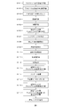
- FIG. 3 is a flow chart showing a method for manufacturing an aluminum alloy substrate for a magnetic disk, an aluminum alloy substrate for a magnetic disk, and a magnetic disk according to the present invention, in which a DC casting method is adopted as a casting method for an aluminum alloy.
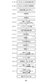
- FIG. 6 is a flow chart showing another method of manufacturing an aluminum alloy substrate for a magnetic disk, an aluminum alloy substrate for a magnetic disk, and a magnetic disk according to the present invention, in which a DC casting method is adopted as a casting method of an aluminum alloy.
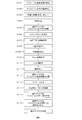
- FIG. 6 is a flow chart showing still another method for producing an aluminum alloy substrate for a magnetic disk, an aluminum alloy substrate for a magnetic disk, and a magnetic disk according to the present invention, in which a DC casting method is adopted as the casting method for the aluminum alloy.
- FIG. 3 is a flow chart showing a method for manufacturing an aluminum alloy substrate for a magnetic disk, an aluminum alloy substrate for a magnetic disk, and a magnetic disk according to the present invention, and adopting a CC casting method as a casting method for an aluminum alloy.
- FIG. 7 is a flow chart showing another method of manufacturing an aluminum alloy substrate for a magnetic disk, an aluminum alloy substrate for a magnetic disk, and a magnetic disk according to the present invention, in which CC casting method is adopted as a casting method of aluminum alloy.
- FIG. 6 is a flow chart showing still another manufacturing method of an aluminum alloy substrate for a magnetic disk, an aluminum alloy substrate for a magnetic disk, and a magnetic disk according to the present invention, in which CC casting method is adopted as a casting method of aluminum alloy.
- the feature of the present invention is that a compound removing step is provided before the grinding step performed before the electroless Ni-P plating step, so that the magnetic disk in which the compound is dispersed by adding Fe to reduce the disk flutter. It is possible to improve the grindability of an aluminum alloy substrate for use and suppress the generation of nodules on the outer peripheral surface and the inner peripheral surface of the aluminum alloy substrate due to electroless Ni-P plating formed when the aluminum alloy substrate is formed later. That's what I did. The effects and detailed mechanisms of these will be described below.
- the inner diameter/outer diameter processing is a step of processing the end surface of the disk blank, that is, the outer peripheral surface defining the outer diameter and the inner peripheral surface defining the inner diameter into a predetermined shape by a cutting machine.
- a plating pretreatment step including an alkaline degreasing treatment step, an acid etching treatment step, a desmut treatment step and a zincate treatment step in this order.
- Electroless Ni-P plating is applied.
- the inner diameter/outer diameter processing is a step of processing the end surface of the disk blank, that is, the outer peripheral surface defining the outer diameter and the inner peripheral surface defining the inner diameter into a predetermined shape by a cutting machine.
- There are various patterns such as “only grinding step”, “preliminary grinding step and subsequent grinding step”, “cutting step and subsequent grinding step”, etc. in the surface processing after the inner diameter and outer diameter processing.
- an aluminum alloy substrate for a magnetic disk in which the plate thickness of the aluminum alloy substrate for a magnetic disk is adjusted, flatness is improved, roughness is adjusted, and waviness is reduced.
- a strain relief heat treatment step and a subsequent compound removal step are provided before grinding.
- the aluminum alloy substrate for a magnetic disk is subjected to a pre-plating step including an alkaline degreasing treatment step, an acid etching treatment step, a desmut treatment step and a zincate treatment step in this order.
- a pre-plating step including an alkaline degreasing treatment step, an acid etching treatment step, a desmut treatment step and a zincate treatment step in this order.
- the zincate treatment step 1st zincate treatment, Zn stripping treatment, and 2nd zincate treatment are carried out in this order.
- the desmutting treatment may not be performed in some cases.
- Electroless Ni-P Plating An aluminum alloy substrate for a magnetic disk that has been subjected to a plating pretreatment step is subjected to an electroless Ni-P plating treatment, and then an aluminum alloy substrate for a magnetic disk (hereinafter simply referred to as "aluminum alloy substrate") There are cases). Nodules having a circular convex shape are scattered on the surface, the back surface, the inner peripheral surface and the outer peripheral surface of the aluminum alloy substrate for a magnetic disk obtained by performing the electroless Ni-P plating treatment.
- abrasion powder is generated and may adhere to the aluminum alloy substrate surface (front surface, back surface, outer peripheral surface, inner peripheral surface). If such abrasion powder adheres, there arises a problem that the magnetic film formed during sputtering becomes nonuniform. Therefore, it is essential to reduce the nodules on the outer peripheral surface of the aluminum alloy substrate as much as possible.
- the above problem does not occur if the number of the protrusions (nodules) having the longest diameter of 4 to 10 ⁇ m on the outer peripheral surface of the aluminum alloy substrate is 300/mm 2 or less, preferably 150/mm 2 or less.
- the convex portion having the longest diameter of less than 4 ⁇ m hardly becomes the above-mentioned abrasion powder, even if it exists, it does not cause any particular problem.
- the convex portion having the longest diameter exceeding 10 ⁇ m is not generated in the electroless Ni—P plating and is not a problem. For this reason, the maximum diameter of the convex portion on the outer peripheral surface is limited to 4 to 10 ⁇ m.
- nodules result from non-uniformity of the surface of the aluminum alloy substrate on which electroless Ni—P plating is performed. It is likely to occur mainly on the compound, on the edge other than the uniform surface such as the end of the hole and the convex portion of the surface.
- electroless Ni-P plating Ni-P is randomly deposited on the entire surface, and the portions forming the islands are deposited to form a uniform film.
- the timing of deposition of Ni-P plating is slightly different from that on the surface, only that portion remains as a convex portion and becomes a nodule.
- the aluminum alloy substrate according to the present invention contains a large amount of compounds, nodules due to the compounds and holes are extremely large on the surface of the aluminum alloy substrate after the electroless Ni-P plating process. Exists.
- the nonuniformity of the end of the hole is also one of the causes of the nodule generation. Occur. Therefore, it is important to suppress the nodules caused by the holes generated in the compound removing step.
- the number of the holes having the longest diameter of 10 ⁇ m or more on the outer peripheral surface of the aluminum alloy substrate is 200 holes/mm 2 or less, preferably 100 holes/mm 2 or less, so that the aluminum alloy after the electroless Ni-P plating step is performed. Generation of nodules on the substrate surface can be suppressed.
- the lower limit value is about 30 pieces/mm 2 . Since the pores having the longest diameter of less than 10 ⁇ m are filled and smoothed by the electroless Ni—P plating, no nodules are generated and no particular problem occurs even if they are formed. Further, the upper limit of the longest diameter of the hole is naturally determined depending on the composition of the aluminum alloy used and the manufacturing method, and in the present invention, the upper limit is about 20 ⁇ m.
- Alloy composition of aluminum alloy substrate for magnetic disk The composition of the aluminum alloy used for the aluminum alloy substrate for magnetic disk according to the present invention is Fe: 0.1 to 3.0 mass% (hereinafter abbreviated as "%"), Cu: 0.005 to 1.000% and Zn: 0.005 to 1.000% are contained as essential elements, and the balance is Al and unavoidable impurities. Further, Mn: 0.1 to 3.0%, Si: 0.1 to 3.0%, Ni: 0.1 to 8.0%, Cr: 0.01 to 1.00%, Zr: 0. One or more selected from 01 to 1.00% may be further contained as the first selection element. Further, one or more selected from Ti, B and V whose total content is 0.005 to 0.500% may be further contained as the second selection element. The contents and functions of these alloy components will be described below.
- Fe 0.1-3.0% Fe is mainly present as second-phase particles (Al—Fe-based compound or the like) and partly exists in solid solution in the parent phase, and has an effect of improving strength and fluttering characteristics of the aluminum alloy substrate.
- Second-phase particles Al—Fe-based compound or the like
- vibration energy is rapidly absorbed by viscous flow at the interface between the second phase particles and the mother phase, and extremely high fluttering characteristics are obtained.
- the Fe content is set in the range of 0.1 to 3.0%.
- the Fe content is preferably in the range of 0.5 to 1.5%.
- Cu 0.005 to 1.000%
- Cu exists mainly as second-phase particles (Al—Cu compound, etc.), and has an effect of improving the strength and fluttering characteristics of the magnetic disk using this aluminum alloy substrate. Further, the zincate film is uniformly, thinly and densely formed, and the effect of improving the smoothness of the electroless Ni-P plating is also exhibited.
- the Cu content is set in the range of 0.005 to 1.000%.
- the Cu content is preferably in the range of 0.005 to 0.400%.
- Zn 0.005 to 1.000% Zn has the effect of forming a zincate film uniformly, thinly and densely, and improving the smoothness and adhesion of electroless Ni-P plating. In addition, the effect of improving the fluttering characteristics of the magnetic disk using this aluminum alloy substrate by forming second phase particles with other additive elements is also exhibited.
- the Zn content is set in the range of 0.005 to 1.000%.
- the Zn content is preferably in the range of 0.100 to 0.700%.
- Mn 0.1-3.0%
- Mn mainly exists as second-phase particles (Al-Mn-based compound, etc.) and has an effect of improving the strength and fluttering characteristics of the magnetic disk using this aluminum alloy substrate.
- vibration energy is rapidly absorbed by viscous flow at the interface between the second phase particles and the mother phase, and extremely high fluttering characteristics are obtained.
- the Mn content is set to the range of 0.1 to 3.0%.
- the Mn content is preferably in the range of 0.1 to 1.0%.
- Si 0.1-3.0%
- Si exists mainly as second-phase particles (Si particles, etc.) and has the effect of improving the strength and fluttering characteristics of a magnetic disk using this aluminum alloy substrate.
- vibration energy is rapidly absorbed by viscous flow at the interface between the second phase particles and the mother phase, and extremely high fluttering characteristics are obtained.
- the Si content is set to the range of 0.1 to 3.0%.
- the Si content is preferably 0.3 to 1.5%.
- Ni 0.1-8.0%
- Ni exists mainly as second-phase particles (Al-Ni compound, etc.) and has the effect of improving the strength and fluttering characteristics of the magnetic disk using this aluminum alloy substrate.
- vibration energy is rapidly absorbed by viscous flow at the interface between the second phase particles and the matrix, and extremely high fluttering characteristics are obtained.
- the Ni content is set to the range of 0.1 to 8.0%.
- the Ni content is preferably 0.3 to 3.0%, more preferably 0.5 to 2.0%.
- Cr 0.01-1.00% Cr exists mainly as second phase particles (Al—Cr compound, etc.) and has the effect of improving the strength and fluttering characteristics of the magnetic disk using this aluminum alloy substrate.
- the Cr content is less than 0.01%, the strength and fluttering characteristics of the magnetic disk using such an aluminum alloy substrate are insufficient.
- the Cr content exceeds 1.00%, a large number of coarse Al—Cr compounds are generated. Even a coarse Al—Cr compound can be removed by the compound removing step, but the recesses formed after removing the compound are large, and a large number of nodules are formed on the outer peripheral surface after electroless Ni—P plating. Is generated. Therefore, the Cr content is in the range of 0.01 to 1.00%.
- the Cr content is preferably in the range of 0.10 to 0.50%, more preferably 0.15 to 0.40%.
- Zr 0.01-1.00%
- Zr exists mainly as second-phase particles (Al-Zr compound, etc.) and has the effect of improving the strength and fluttering characteristics of a magnetic disk using this aluminum alloy substrate.
- the Zr content is less than 0.01%, the strength and fluttering characteristics of the magnetic disk using such an aluminum alloy substrate are insufficient.
- the Zr content exceeds 1.00%, a large number of coarse Al—Zr compounds are produced. Even a coarse Al—Zr-based compound can be removed by the compound removing step, but the dents formed after the compound removal are large, and a large number of nodules are formed on the outer peripheral surface after electroless Ni—P plating.
- the Zr content is set to the range of 0.01 to 1.00%.
- the Zr content is preferably in the range of 0.10 to 0.50%.
- Ti, B, V 0.005 to 0.500%
- Ti, B and V form second phase particles (boride such as TiB 2 or Al 3 Ti or Ti-VB particles) in the solidification process during casting, and these become crystal grain nuclei. Therefore, it has an effect of refining crystal grains.
- the crystal grains finer, it is possible to suppress the non-uniformity of the size of the second phase grains and reduce the variations in strength and fluttering characteristics in the magnetic disk using this aluminum alloy substrate. If the total content of Ti, B and V is less than 0.005%, the above effect cannot be obtained. Even if the total content of Ti, B and V exceeds 0.500%, the effect is saturated, so that a significant improvement effect cannot be obtained.
- the total content of Ti, B and V is set in the range of 0.005 to 0.500%.
- the total content of Ti, B and V is preferably in the range of 0.005 to 0.100%.
- the total content of Ti, B and V is the total of three elements when all of these elements are contained, the total of these two elements when only two elements are contained, and only one element. When contained, it is the total of this one element.
- the balance of the aluminum alloy base material used for the aluminum alloy substrate of the present invention consists of Al and unavoidable impurities.
- unavoidable impurities include Mg, Pb, Ga, and Sn. If the content of each is less than 0.10% and less than 0.20% in total, the aluminum alloy substrate obtained by the present invention is used. It does not spoil the characteristics.
- the aluminum alloy substrate with reduced disk flutter according to the present invention contains Fe and thus has a large compound and a high existence density. Therefore, a large amount of nodules are generated on the aluminum alloy substrate after the electroless Ni-P plating process. However, as described above, nodules are removed from the front surface and the back surface of the aluminum alloy substrate by the polishing process, so that there is no problem. On the other hand, the nodules generated on the inner and outer peripheral surfaces of the aluminum alloy base remain as they are. Therefore, the compound removal step is applied to the aluminum alloy substrate to remove the compounds on the inner and outer peripheral surfaces in advance, so that the inner peripheral surface of the aluminum alloy substrate after the electroless Ni-P plating step is removed. It is possible to prevent the generation of nodules on the outer peripheral surface.
- the compound referred to in the present invention means an intermetallic compound such as Al-Fe and Al-Fe-Mn.
- the compound remaining on the surface of the aluminum alloy substrate is removed with a chemical solution.
- the chemical solution used is an HNO 3 solution of 10 to 60 mass% (hereinafter abbreviated as “%”) at 10 to 30° C., which is a mixed solution of HNO 3 /HF containing 10 to 80 g/L of HF ( Hereinafter, simply referred to as “mixed solution”) is used.
- This mixed solution has a strong etching power and particularly increases the dissolution rate of the aluminum alloy substrate around the compound.
- the compound is removed by melting the aluminum alloy substrate around the compound, and only the compound on the surface of the aluminum alloy substrate can be selectively removed.
- the HF concentration is less than 10 g/L and the HNO 3 concentration is less than 10%, the etching power is weak and the compound on the surface of the aluminum alloy substrate cannot be sufficiently removed.
- the concentration of HF exceeds 80 g/L and the concentration of HNO 3 exceeds 60%, the etching force is too strong and the dissolution of the parent phase of the aluminum alloy substrate proceeds. As a result, the unevenness of the surface of the aluminum alloy substrate becomes large, and the smoothness of the electroless Ni-P plated surface formed in the subsequent electroless Ni-P plating step cannot be obtained.
- the HF concentration is preferably 20-60 g/L and the HNO 3 concentration is preferably 25-50%.
- the temperature of the mixed solution should be 10 to 30°C. If it is less than 10°C, the reaction rate is slow and the compound on the surface of the aluminum alloy substrate cannot be sufficiently removed. On the other hand, if the temperature exceeds 30° C., the reaction rate becomes too fast and the dissolution of the mother phase of the aluminum alloy substrate proceeds, so that the irregularities on the surface of the aluminum alloy substrate become large.
- the temperature of the mixed solution is preferably 15 to 25°C.
- the treatment time in the compound removing step is 5 to 60 seconds. If it is less than 5 seconds, the reaction time is too short to sufficiently remove the compound on the surface of the aluminum alloy substrate. On the other hand, if it exceeds 60 seconds, the reaction time becomes too long and the dissolution of the mother phase of the aluminum alloy substrate proceeds, so that the irregularities on the surface of the aluminum alloy substrate become large.
- the processing time is preferably 10 to 30 seconds.
- the compound removal process is carried out before the aluminum alloy substrate grinding process.
- the order of "inner diameter outer diameter processing step-strain relief heat treatment step-compound removal step-grinding step” or “inner diameter outer diameter machining step-preliminary grinding step-strain relief heat treatment step-compound removal step” is adopted.
- the aluminum alloy plate thus produced is punched into an annular shape to form an annular disk blank (S107), and the disk blank is subjected to pressure flattening annealing treatment (S108). Further, the inner and outer peripheral surfaces of the disk blank are subjected to inner and outer diameter processing (S109), strain relief heating processing (S110), compound removal (S111), and grinding processing (S112). Instead of the steps S109 to S112, as shown in FIG. 2, inner diameter/outer diameter machining is performed (S109), pre-grinding machining (S109-1), strain relief heating treatment (S110), and compound removal (S111). ), grinding processing (S112) may be given. Further, as shown in FIG.
- the molten aluminum alloy is prepared by heating and melting it in a usual manner so as to have a predetermined alloy composition range.
- the molten aluminum alloy thus prepared is cast according to the semi-continuous casting method (DC casting method).
- the cooling rate during casting is preferably in the range of 0.1 to 1000° C./s.
- Homogenization treatment step Next, the cast aluminum alloy ingot is subjected to a homogenization treatment, if necessary.
- Conditions for the homogenization treatment are not particularly limited, and for example, one-stage heat treatment at 500° C. or higher for 0.5 hours or longer can be used.
- the upper limit of the heating temperature during the homogenization treatment is not particularly limited, but if it exceeds 650°C, melting of the aluminum alloy may occur, so the upper limit is 650°C.
- the hot rolling start temperature is preferably 300 to 550° C. when the homogenizing treatment is performed, and the hot rolling end temperature is preferably less than 380° C. and 300° C. or less. Is more preferable.
- the lower limit of the hot rolling finish temperature is not particularly limited, but the lower limit is set to 200° C. to prevent the occurrence of defects such as edge cracks.
- the hot rolling start temperature is preferably 380°C or lower, and more preferably 350°C or lower.
- the hot rolling finish temperature is not particularly limited, but the lower limit is 200° C. in order to prevent the occurrence of defects such as edge cracks.
- the hot rolled sheet is processed into a cold rolled sheet of about 0.45 to 1.8 mm by cold rolling.
- the hot rolled plate is finished by cold rolling to a required product plate thickness.
- the conditions for cold rolling are not particularly limited, and may be determined according to the required product plate strength and plate thickness, and the cold rolling rate is preferably 10 to 95%.
- an annealing treatment step may be provided in order to ensure cold rolling workability.
- the condition is a temperature of 200° C. or higher and 380° C. or lower for 0.1 to 10 hours.
- Disc blank punching process and pressure flattening annealing treatment process The aluminum alloy plate produced as described above is punched into an annular shape to prepare an annular aluminum alloy plate. Next, the annular aluminum alloy plate is subjected to pressure flattening annealing treatment at 220 to 450° C. for 30 minutes or more to prepare a flattened annular disc blank.
- the flattened disk blank is processed with an inner diameter and outer diameter (S109), a strain relief heat treatment (S110), and a compound removal (S111).
- a grinding process is performed (S112), or, as shown in FIG. 2, a preliminary grinding process (S109-1) is provided between S109 and S110 in the process of FIG. 1, or as shown in FIG.
- a cutting process is provided between S109 and S110 in the process of FIG.
- the aluminum alloy plate is preferably heat treated at a temperature of 250 to 400° C. for 5 to 15 minutes.
- the compound removal (S111) is performed as described above. An aluminum alloy substrate is obtained by the above.
- Manufacturing method of aluminum alloy substrate for magnetic disk according to second invention 9-1.
- Outline A method of manufacturing an aluminum alloy substrate for a magnetic disk according to the present invention will be described with reference to FIG.
- a molten metal is melted so as to have a predetermined alloy composition (S101), continuously cast (S102), and the ingot is subjected to any homogenization treatment (S103), Cold rolling (S104) is performed to produce an aluminum alloy plate (S105).
- S101 predetermined alloy composition
- S102 continuously cast
- S104 Cold rolling
- the rolled plate may be subjected to an optional annealing treatment.
- the aluminum alloy plate thus produced is punched into an annular shape to form an annular disk blank (S106), and the disk blank is subjected to pressure flattening annealing treatment (S107). Further, the inner and outer peripheral surfaces of the disk blank are subjected to inner and outer diameter processing (S108), strain relief heating processing (S109), compound removal (S110), and grinding processing (S111).
- inner and outer diameter processing S108
- strain relief heating processing S109
- S110 compound removal
- grinding processing S111
- inner diameter/outer diameter machining is performed (S108), pre-grinding machining (S108-1), strain relief heating treatment (S109), and compound removal (S110).
- grinding processing (S111) may be given. Further, as shown in FIG.
- the molten aluminum alloy is prepared by heating and melting it in a usual manner so as to have a predetermined alloy composition range.
- a thin cast plate of aluminum alloy having a thickness of about 2.0 to 10.0 mm is cast by a continuous casting method (CC casting method).
- the molten metal is supplied between a pair of rolls (or belt casters, block casters) through a casting nozzle, and the aluminum alloy cast plate is directly cast by heat removal from the rolls.
- the temperature of the cast plate 10 minutes after the casting is 150° C. or higher and lower than 230° C.
- the temperature of the cast plate after 1 minute has passed from the casting to 230 to 350° C.
- the temperature of the cast plate after 10 minutes has passed from the casting to 150° C. or higher and lower than 230° C.
- a large number of second-phase particles (mainly Al-Fe compounds) can be distributed to obtain an effect of improving strength. Due to such a large number of fine distributions of the second phase particles, it is possible to further enhance the effect of improving the strength as compared with the DC casting method.
- methods such as fan air cooling, mist cooling, shower cooling and water cooling can be adopted.
- a homogenization treatment is carried out on the cast aluminum alloy cast plate, if necessary.
- the conditions for the homogenization treatment are not particularly limited, and for example, heating conditions of 300 to 450° C. for 0.5 to 24 hours are preferable. As a result, it is possible to obtain the effect of suppressing the nonuniformity of the size of the second phase particles and reducing the variations in the strength and fluttering characteristics of the aluminum alloy substrate.
- the hot rolled sheet is processed into a cold rolled sheet of about 0.45 to 1.8 mm by cold rolling.
- the hot rolled plate is finished by cold rolling to a required product plate thickness.
- the conditions for cold rolling are not particularly limited, and may be determined according to the required product plate strength and plate thickness, and the cold rolling rate is preferably 10 to 95%.
- an annealing treatment step may be provided in order to ensure cold rolling workability.
- the condition is a temperature of 200° C. or higher and 380° C. or lower for 0.1 to 10 hours.
- Disc blank punching process and pressure flattening annealing treatment process The aluminum alloy plate produced as described above is punched into an annular shape to prepare an annular aluminum alloy plate. Next, the annular aluminum alloy plate is subjected to pressure flattening annealing treatment at 220 to 450° C. for 30 minutes or more to prepare a flattened annular disc blank.
- the flattened disc blank is processed with an inner diameter and outer diameter (S108), a strain relief heat treatment (S109), and a compound removal (S110).
- a grinding process is performed (S111), or as shown in FIG. 2
- a preliminary grinding step (S108-1) is provided between S108 and S109 in the step of FIG. 1, or as shown in FIG.
- a cutting process (S108-2) is provided between S108 and S109 in the process of FIG.
- the strain removal heat treatment step the aluminum alloy plate is preferably heat treated at a temperature of 250 to 400° C. for 5 to 15 minutes.
- the compound removal (S110) is performed as described above.
- An aluminum alloy substrate is obtained by the above.
- AD-68F manufactured by Uemura Kogyo
- a treatment time of 3 to 10 minutes a concentration of 200 to 800 mL/L
- a concentration of 200 to 800 mL/L a commercially available AD-107F (manufactured by Uemura Kogyo) etching solution or the like, and perform the acid etching under the conditions of a temperature of 50 to 75° C., a treatment time of 0.5 to 5 minutes, and a concentration of 20 to 100 mL/L. Is preferred.
- the first zincate treatment should be performed using a commercially available AD-301F-3X (manufactured by Uemura Kogyo) zincate treatment solution at a temperature of 10 to 35° C., a treatment time of 0.1 to 5 minutes, and a concentration of 100 to 500 mL/L. Is preferred.
- the second zincate treatment is carried out under the same conditions as the first zincate treatment.
- An electroless Ni-P plating process is performed as a base plating process on the surface of the 2nd zincate treated aluminum alloy substrate (S115 in FIG. 1, S114 in FIG. 4).
- electroless Ni-P plating use a commercially available Nimden HDX (Kamimura Kogyo) plating solution or the like at a temperature of 80 to 95° C., a treatment time of 30 to 180 minutes, and a Ni concentration of 3 to 10 g/L. Treatment is preferred.
- an aluminum alloy substrate for a magnetic disk subjected to a base plating process can be obtained (S116 in FIG. 1, S115 in FIG. 4).
- the surface of the aluminum alloy base plate subjected to the undercoating treatment is smoothed by polishing, a ground layer is provided on the polished surface, and a magnetic layer is deposited on the ground layer by sputtering to form (see FIG. 1). S117, S116 of FIG. 4), and the magnetic disk is used. It is preferable to further provide a protective film and a lubricating layer on the magnetic layer.
- First Example Inventive Examples 1 to 47, Comparative Examples 1 to 23 In the first embodiment, an example in which a DC casting method is used as a casting method for an aluminum alloy is shown. First, each aluminum alloy having the component composition shown in Table 1 was melted according to a conventional method to melt an aluminum alloy melt. Next, the molten aluminum alloy was cast by a DC casting method to produce an ingot. Both sides of the ingot 15 mm were faced and homogenized at 520° C. for 1 hour. Next, hot rolling was performed at a hot rolling start temperature of 460° C. and a hot rolling end temperature of 280° C. to obtain a hot rolled plate having a plate thickness of 3.0 mm.
- the hot-rolled sheet was cold-rolled (rolling rate: 73.3%) without intermediate annealing to a sheet thickness of 0.8 mm to obtain a final rolled sheet.
- the aluminum alloy plate thus obtained was punched into an annular shape having an outer diameter of 98 mm and an inner diameter of 24 mm to produce an annular aluminum alloy plate.
- "-" indicates less than the detection limit.
- the annular aluminum alloy plate obtained as described above was subjected to pressure flattening annealing at 300° C. for 3 hours under a pressure of 1.5 MPa to obtain a disk blank.
- the disc blank was subjected to the steps shown in Tables 2 and 3 to produce an aluminum alloy substrate, and the outer peripheral surface was observed and evaluated.
- the outer diameter was 97 mm and the inner diameter was 25 mm by cutting the inner and outer diameters.
- “ ⁇ ” indicates the same as the above column.
- C1 indicates "outer diameter 97 mm, inner diameter 25 mm" as described in the column above it.
- C2 is the same as C1 and has an "outer diameter of 97 mm and an inner diameter of 25 mm", and similarly, C3 to C27 also have a "outer diameter of 97 mm and an inner diameter of 25 mm". The same applies to the strain removal heat treatment and the like.
- the aluminum alloy substrate was subjected to plating pretreatment.
- a 1st zincate treatment was carried out for 50 seconds with a 25°C zincate treatment liquid (AD-301F, manufactured by Uemura Kogyo) at a concentration of 300 mL/L.
- the zincate (Zn) layer was peeled off with a 30% HNO 3 aqueous solution (25° C.) for 60 seconds, and the concentration of the 25° C. zincate treatment liquid (AD-301F, manufactured by Uemura Kogyo) was 300 mL/L for 1 minute.
- the 2nd zincate treatment was performed again.
- Ni-P is electroless-plated to a thickness of 14 ⁇ m on a 2nd zincate-treated aluminum alloy substrate using a 90° C. electroless Ni-P plating solution (Nimden HDX, manufactured by Uemura Kogyo Co., Ltd.) (120 minutes). Then, final polishing with a cloth (polishing amount on one side: 4 ⁇ m) was performed to obtain an aluminum alloy substrate for evaluation. Then, the outer peripheral surface was evaluated by observation.
- electroless Ni-P plating solution Ni-P plating solution (Nimden HDX, manufactured by Uemura Kogyo Co., Ltd.) (120 minutes). Then, final polishing with a cloth (polishing amount on one side: 4 ⁇ m) was performed to obtain an aluminum alloy substrate for evaluation. Then, the outer peripheral surface was evaluated by observation.
- Evaluation 1 Observation of outer peripheral surface after grinding processing An aluminum alloy substrate after grinding processing immediately before plating pretreatment was used as a sample for evaluation, and the outer peripheral surface was measured with a digital microscope (VHX-6000 manufactured by KEYENCE) at a magnification of 2000 times. The field of view was taken. From the photographed image, the maximum diameter of the holes was measured and the number was evaluated. From an average of five visual fields was calculated number of pores per 1 mm 2, if the maximum diameter 10 ⁇ m or more holes is less than 100 / mm 2 excellent ( ⁇ ), there 100 / mm 2 200 pieces / mm 2 or less or more If it was more than 200 pieces/mm 2 , it was considered as bad (x). ⁇ and ⁇ were passed, and x was rejected. The results are shown in Tables 4 and 5.
- Evaluation 2 Observation of the outer peripheral surface of the aluminum alloy substrate after the electroless Ni-P plating treatment
- the aluminum alloy substrate after the electroless Ni-P plating treatment was used as a sample for evaluation, and this outer peripheral surface was viewed by SEM at 5 times the field of view by 1000 times. I took a picture. From the photographed image, the maximum diameter of the convex portion was measured and the number thereof was evaluated.
- the number of protrusions per 1 mm 2 was calculated from the average of 5 fields of view, and if the number of protrusions with a maximum diameter of 4 to 10 ⁇ m was less than 150/mm 2 , excellent ( ⁇ ), 150/mm 2 or more and 300/mm If it was 2 or less, it was good ( ⁇ ), and if it was more than 300 pieces/mm 2 , it was bad (x). ⁇ and ⁇ were passed, and x was rejected. The results are shown in Tables 4 and 5.
- Evaluation 3 Plating smoothness
- the aluminum alloy substrate after electroless Ni—P plating was used as a sample for evaluation, and this was immersed in 50 vol% nitric acid at 50° C. for 3 minutes to etch the Ni—P plated surface.
- the Ni-P plated surface after etching was photographed in 5 fields of view using an SEM at a magnification of 5000 times.
- the area of one visual field was 536 ⁇ m 2 .
- the number of plating defects was measured from the images captured in 5 fields of view, and the arithmetic mean value of the 5 fields of view was obtained.
- Evaluation 4 Fluttering characteristics The fluttering characteristics were evaluated using an aluminum alloy substrate after electroless Ni-P plating and surface polishing as a sample for evaluation. Although a magnetic disk coated with a magnetic material as a product should be evaluated, it has been confirmed that the evaluation results of the aluminum alloy base are the same as those of the magnetic disk.
- the sample for evaluation was placed on a commercially available hard disk drive in the presence of air and measured.
- the hard disk drive was a Seagate ST2000 (trade name), and the motor was driven by directly connecting a Techno Alive SLD102 (trade name) to the motor.
- the number of rotations was 7200 rpm, and a plurality of disks were always installed, and the surface vibration was observed on the surface of the magnetic disk on the upper side by a laser Doppler meter LDV1800 (trade name) manufactured by Ono Sokki.
- the observed vibration was spectrally analyzed by an FFT analyzer DS3200 (trade name) manufactured by Ono Sokki.
- the observation was performed by making a hole in the lid of the hard disk drive and observing the disk surface through the hole.
- the squeeze plate installed on the commercially available hard disk was removed and evaluated.
- Fluttering characteristics were evaluated by the maximum displacement (disk fluttering (nm)) of a broad peak near 300 to 1500 Hz where fluttering appears. This broad peak is called NRRO (Non-Repeatable Run Out) and is known to have a great influence on the positioning error of the head.
- the fluttering characteristics were evaluated as excellent ( ⁇ ) in the case of 30 nm or less in air, good ( ⁇ ) in the range of more than 30 nm and 50 nm or less, and poor (x) in the case of more than 50 nm. ⁇ and ⁇ were passed, and x was rejected. The results are shown in Tables 4 and 5.
- the invention examples 1 to 23 and the comparative examples 1 to 12 are examples in which the composition of the aluminum alloy was changed, and the invention examples 24 to 47 and the comparative examples 13 to 23 were different in the treatment process of the aluminum alloy substrate. This is an example.
- Comparative Example 2 a large amount of Fe was contained, so that there were many coarse Al—Fe compounds, and there were many holes after the compound removal step, and accordingly many protrusions after Ni—P plating. As a result, the plating smoothness was unacceptable.
- the CC casting method is used as an aluminum alloy casting method.
- each aluminum alloy having the component composition shown in Table 1 was melted according to a conventional method to melt an aluminum alloy melt.
- the molten aluminum alloy was cast by the CC casting method to produce a thin cast plate having a thickness of 6 mm.
- the cast plate was cold-rolled to a plate thickness of 0.8 mm to obtain a final rolled plate.
- the aluminum alloy plate thus obtained was punched into an annular shape having an outer diameter of 98 mm and an inner diameter of 24 mm to produce an annular aluminum alloy plate.
- the annular aluminum alloy plate obtained as described above was subjected to pressure flattening annealing at 300° C. for 3 hours under a pressure of 1.5 MPa to obtain a disk blank.
- the disc blank was subjected to the steps shown in Tables 2 and 3 to produce an aluminum alloy substrate, and the outer peripheral surface was evaluated by observation.
- the outer diameter was 97 mm and the inner diameter was 25 mm by cutting the inner and outer diameters.
- the aluminum alloy substrate was subjected to plating pretreatment.
- a 1st zincate treatment was carried out for 50 seconds with a 25°C zincate treatment liquid (AD-301F, manufactured by Uemura Kogyo) at a concentration of 300 mL/L.
- AD-301F 25°C zincate treatment liquid
- the zincate (Zn) layer was peeled off with a 30% HNO 3 aqueous solution (25° C.) for 60 seconds, and the zincate treatment liquid (AD-301F, manufactured by Uemura Kogyo Co., Ltd.) at a concentration of 300 mL/L was used for 1 minute.
- the 2nd zincate treatment was performed again.
- Ni-P is electroless-plated to a thickness of 14 ⁇ m on a 2nd zincate-treated aluminum alloy substrate using a 90° C. electroless Ni-P plating solution (Nimden HDX, manufactured by Uemura Kogyo Co., Ltd.) (120 minutes). Then, final polishing with a cloth (polishing amount on one side: 4 ⁇ m) was performed to obtain an aluminum alloy substrate for evaluation. Then, the outer peripheral surface was evaluated by observation.
- electroless Ni-P plating solution Ni-P plating solution (Nimden HDX, manufactured by Uemura Kogyo Co., Ltd.) (120 minutes). Then, final polishing with a cloth (polishing amount on one side: 4 ⁇ m) was performed to obtain an aluminum alloy substrate for evaluation. Then, the outer peripheral surface was evaluated by observation.
- Evaluation 1 Observation of outer peripheral surface after grinding processing An aluminum alloy substrate after grinding processing immediately before plating pretreatment was used as a sample for evaluation, and the outer peripheral surface was measured with a digital microscope (VHX-6000 manufactured by KEYENCE) at a magnification of 2000 times. The field of view was taken. From the photographed image, the maximum diameter of the holes was measured and the number thereof was evaluated. From an average of five visual fields was calculated number of pores per 1 mm 2, if the maximum diameter 10 ⁇ m or more holes is less than 100 / mm 2 excellent ( ⁇ ), there 100 / mm 2 200 pieces / mm 2 or less or more If it was more than 200 pieces/mm 2 , it was considered as bad (x). ⁇ and ⁇ were passed, and x was rejected. The results are shown in Tables 6 and 7.
- Evaluation 2 Observation of the outer peripheral surface of the aluminum alloy substrate after the electroless Ni-P plating treatment
- the aluminum alloy substrate after the electroless Ni-P plating treatment was used as a sample for evaluation, and this outer peripheral surface was viewed by SEM at 5 times the field of view by 1000 times. I took a picture. From the photographed image, the maximum diameter of the convex portion was measured and the number thereof was evaluated.
- the number of protrusions per 1 mm 2 was calculated from the average of 5 fields of view, and if the number of protrusions with a maximum diameter of 4 to 10 ⁇ m was less than 150/mm 2 , excellent ( ⁇ ), 150/mm 2 or more and 300/mm If it was 2 or less, it was good ( ⁇ ), and if it was more than 300 pieces/mm 2 , it was bad (x). ⁇ and ⁇ were passed, and x was rejected. The results are shown in Tables 6 and 7.
- Evaluation 3 Plating smoothness
- the aluminum alloy substrate after electroless Ni—P plating was used as a sample for evaluation, and this was immersed in 50 vol% nitric acid at 50° C. for 3 minutes to etch the Ni—P plated surface.
- the Ni-P plated surface after etching was photographed in 5 fields of view using an SEM at a magnification of 5000 times.
- the area of one visual field was 536 ⁇ m 2 .
- the number of plating defects was measured from the images captured in 5 fields of view, and the arithmetic mean value of the 5 fields of view was obtained.
- Evaluation 4 Fluttering characteristics The fluttering characteristics were evaluated using an aluminum alloy substrate after electroless Ni-P plating and surface polishing as a sample for evaluation. Although a magnetic disk coated with a magnetic material as a product should be evaluated, it has been confirmed that the evaluation results of the aluminum alloy base are the same as those of the magnetic disk.
- the sample for evaluation was placed on a commercially available hard disk drive in the presence of air and measured.
- the hard disk drive was a Seagate ST2000 (trade name), and the motor was driven by directly connecting a Techno Alive SLD102 (trade name) to the motor.
- the number of rotations was 7200 rpm, and a plurality of disks were always installed, and the surface vibration was observed on the surface of the magnetic disk on the upper side by a laser Doppler meter LDV1800 (trade name) manufactured by Ono Sokki.
- the observed vibration was spectrally analyzed by an FFT analyzer DS3200 (trade name) manufactured by Ono Sokki.
- the observation was performed by making a hole in the lid of the hard disk drive and observing the disk surface through the hole.
- the squeeze plate installed on the commercially available hard disk was removed and evaluated.
- Fluttering characteristics were evaluated by the maximum displacement (disk fluttering (nm)) of a broad peak near 300 to 1500 Hz where fluttering appears. This broad peak is called NRRO (Non-Repeatable Run Out) and is known to have a great influence on the positioning error of the head.
- the fluttering characteristics were evaluated as excellent ( ⁇ ) in the case of 30 nm or less in air, good ( ⁇ ) in the range of more than 30 nm and 50 nm or less, and poor (x) in the case of more than 50 nm. ⁇ and ⁇ were passed, and x was rejected. The results are shown in Tables 6 and 7.
- the invention examples 48 to 70 and the comparative examples 24 to 35 are examples in which the composition of the aluminum alloy was changed, and the invention examples 71 to 94 and the comparative examples 36 to 46 were different in the treatment process of the aluminum alloy substrate. This is an example.
- Comparative Example 26 the amount of second phase particles was small due to the low Cu content, and the fluttering characteristic was unacceptable. In addition, the zincate coating was non-uniform and defects were generated on the plating surface, so the plating smoothness also failed.
- Comparative Example 34 the content of Cr was large, so that there were many coarse Al—Cr-based compounds and they could not be removed even by applying the compound removal step. Therefore, after the Ni—P plating, a protrusion on the outer peripheral surface and a defect on the plating surface were generated, and the plating smoothness was unacceptable.
- the number of mounted magnetic disks is increased due to the thinning of magnetic disks, and It is possible to provide a magnetic disk that enables an increase in storage capacity and contributes to an increase in HDD capacity.
Landscapes
- Chemical & Material Sciences (AREA)
- Engineering & Computer Science (AREA)
- Metallurgy (AREA)
- Organic Chemistry (AREA)
- Materials Engineering (AREA)
- Mechanical Engineering (AREA)
- Chemical Kinetics & Catalysis (AREA)
- General Chemical & Material Sciences (AREA)
- Inorganic Chemistry (AREA)
- Physics & Mathematics (AREA)
- Crystallography & Structural Chemistry (AREA)
- Thermal Sciences (AREA)
- Manufacturing Of Magnetic Record Carriers (AREA)
- Magnetic Record Carriers (AREA)
- Chemically Coating (AREA)
- ing And Chemical Polishing (AREA)
- Manufacturing & Machinery (AREA)
Abstract
Fe:0.1~3.0mass%、Cu:0.005~1.000mass%、Zn:0.005~1.000mass%を含有し、残部Al及び不可避不純物からなるアルミニウム合金からなり、外周面において、最長径10μm以上の孔が200個/mm2以下であることを特徴とする磁気ディスク用アルミニウム合金基板、これを用いた磁気ディスク用アルミニウム合金基盤及び磁気ディスク、ならびに、これらの製造方法。
Description
本発明は、ディスクフラッタが小さく、かつ、無電解Ni-Pめっき表面の異常部を低減した磁気ディスク用アルミニウム合金基盤及びその製造方法、当該磁気ディスク用アルミニウム合金基盤を製造するための磁気ディスク用アルミニウム合金基板及びその製造方法、ならびに、当該磁気ディスク用アルミニウム合金基盤を用いた磁気ディスク及びその製造方法に関する。
コンピュータやデータセンターの記憶装置に用いられるアルミニウム合金製の磁気ディスク基板は、良好なめっき性を有すると共に機械的特性や加工性に優れる基板を用いて製造される。例えばJIS5086(3.5mass%以上4.5mass%以下のMg、0.50mass%以下のFe、0.40mass%以下のSi、0.20mass%以上0.70mass%以下のMn、0.05mass%以上0.25mass%以下のCr、0.10mass%以下のCu、0.15mass%以下のTi及び0.25mass%以下のZnを含有し、残部Al及び不可避的不純物からなる)からなるアルミニウム合金を基本とした基板から製造されている。
一般的なアルミニウム合金製の磁気ディスクは、まず円環状アルミニウム合金基板を作製し、このアルミニウム合金基板にめっきを施し、次いで、その表面に磁性体を付着させることにより製造されている。
例えば、前記JIS5086合金からなるアルミニウム合金製の磁気ディスクは、以下の製造工程により製造される。まず、所望の化学成分としたアルミニウム合金を鋳造し、その鋳塊に均質化処理を施した後に熱間圧延し、次いで冷間圧延を施し、磁気ディスクとして必要な厚さを有する圧延材を作製する。この圧延材には、必要に応じて冷間圧延の途中等に焼鈍を施すことが好ましい。次に、この圧延材を円環状に打抜き、それまでの製造工程により生じた歪み等を除去するために、円環状に打抜いたアルミニウム合金板を積層し、上下の両面から加圧しつつ焼鈍を施して平坦化する加圧焼鈍を行うことにより、円環状のアルミニウム合金のディスクブランクが作製される。
このようにして作製されたディスクブランクに、前処理として切削加工、研削加工、脱脂処理、エッチング処理、デスマット処理、ジンケート処理(Zn置換処理)を順次施す。次いで、下地処理として硬質非磁性金属であるNi-Pを無電解めっきし、そのめっき表面を研磨により平滑とした後に、Ni-Pを無電解めっき表面に磁性体をスパッタリングしてアルミニウム合金製の磁気ディスクが製造される。
ところで、近年ではHDDを取り巻く環境の変化が激しい。これまで,HDDは主としてデスクトップパソコンへの搭載が主流であったが、現在ではノートパソコン、タブレット、スマートフォン等のSSDを搭載する端末の台頭により、デスクトップパソコンの需要は右肩下がりである。しかしながら、前記端末の需要が増えるにつれてクラウドサービスが発展し,それに伴うデータセンターの新設、拡張が盛んである。データセンターでは、未だHDDが主流であり、今後も需要は伸び続けることが予想されている。
データセンターに使用されるHDDは、大容量化と高密度化、更には高速化を満足することが不可欠となってきている。HDDを大容量化するには、記憶装置に搭載する磁気ディスクの枚数を増加させることが最も効果的であるが、そのためには磁気ディスク用のアルミニウム合金基材の薄肉化が必須である。
しかしながら、磁気ディスク用のアルミニウム合金基材を単純に薄肉化すると、高速回転時の流体力の増加による励振力が増加し、ディスクフラッタ発生の問題を招く。ディスクフラッタは、磁気ディスクを高速で回転させるとディスク間に不安定な気流が発生し、その気流により磁気ディスクの振動(フラッタリング)が発生することに起因する。このような現象は、アルミニウム合金基材の剛性が小さいと磁気ディスクの振動が大きくなり、読み取り部であるヘッドがその変化に追従できないために発生するものである。フラッタリングが発生するとヘッドの位置決め誤差が増加するため、ディスクフラッタの減少が強く求められている。
また、HDDの大容量化には、磁気ディスク1枚当たりの記憶容量を増加させることも有効である。無電解Ni-Pめっき表面に、例えばピットのような欠陥や、外部からの付着物が存在すると、これら異常部周辺を除外してデータの読み書きを行わなければならない。その結果、異常部の数に比例して磁気ディスク1枚当たりの記憶容量が低下する。このように、記憶容量の増加には無電解Ni-Pめっき表面の異常部を低減することが必要不可欠である。
このような実情から、最近ではディスクフラッタを低減し、且つ、無電解Ni-Pめっき表面の異常部を低減するという両方の特性を有するアルミニウム合金製の磁気ディスク基板が強く望まれている。ディスクフラッタを小さくするには、従来使用されている例えばJIS5086等のAl-Mg系合金では実現することができない。ディスクフラッタを小さくするには、アルミニウム合金中に化合物を多量に分布させることが効果的であることから、これまで検討されていなかった合金種の適用が必要である。
しかしながら、アルミニウム合金中の化合物が増加するに伴って無電解Ni-Pめっき表面の異常部も増加してしまうという考えがこれまでの磁気ディスク用アルミニウム基板の常識であり、従来のアルミニウム合金基材ではFe及びSiの含有量を低減することを対策としてきた。ディスクフラッタを低減し、且つ、無電解Ni-Pめっき表面の異常部を低減するという両方の特性を満たすためには、相反する二つの課題を同時に解決する必要がある。また、薄肉化に伴い耐衝撃性の低下も懸念されるため、強度は可能な限り高い事が望ましい。
例えば特許文献1には、ディスクフラッタを小さくするために多量のSiを添加したアルミニウム合金基材の組成が開示されている。また、特許文献2には、無電解Ni-Pめっき工程中の洗浄水に硫酸イオンを添加することで、めっき欠陥を抑制する技術が開示されている。
しかしながら、特許文献1に開示されているアルミニウム合金基板では、多量のSiが添加されているため研削加工が困難であることに加え、アルミニウム合金基板表面のSiを除去することが困難であり、無電解Ni-Pめっき表面の異常部が増加するという問題を解決できていなかった。また、特許文献2の技術は、化合物が少ないアルミニウム合金基板の場合に効果を発揮するものであり、ディスクフラッタを小さくするために化合物を分散させた場合には効果が期待できない問題があった。
本発明は、上記実情に鑑みてなされたものであり、ディスクフラッタが小さく、かつ、無電解Ni-Pめっき表面の異常部を低減した磁気ディスク用アルミニウム合金基盤及びその製造方法、当該磁気ディスク用アルミニウム合金基盤を製造するための磁気ディスク用アルミニウム合金基板及びその製造方法、ならびに、当該磁気ディスク用アルミニウム合金基盤を用いた磁気ディスクの提供を目的とする。
本発明者らは、アルミニウム合金基材中の化合物とディスクフラッタ及びめっき性の関係について鋭意研究を重ねた。その結果、アルミニウム合金基板の組成において、Fe添加によりディスクフラッタを低減できることを見出した。更に、Feを添加したアルミニウム合金基板中の化合物は、表面全体に密に分布することでカソードサイトが分散し,均一な反応となることで、後のアルミニウム合金基盤とする際に形成される無電解Ni-Pめっき表面のピットのような欠陥を低減できることも見出した。これらの結果より、材料として当初の目的は達成されたが、製造工程における課題が新たに浮上した。
アルミニウム合金基板の表面全体に密に分布する化合物は、母相よりも硬いため研削加工時の速度を低下させる影響が明らかになった。また、アルミニウム合金基板の端面(外周面及び内周面)では、後に形成される無電解Ni-Pめっき後に化合物や孔などに起因するめっきの凸部(ノジュール)が発生し、これが端面から脱落した後にアルミニウム合金基盤の様々な面に付着して、異常部となる事が判明した。ここで、アルミニウム合金基盤の表面と裏面では、研磨工程によりノジュールは除去される。しかしながら、端面では無電解Ni-Pめっき後に処理が施されないために、発生したノジュールが除去されないまま残存して後の工程に悪影響を及ぼす。
このような新たな製造上の課題を解決するため、本発明者らは更に研究を重ねた。その結果、無電解Ni-Pめっき工程の前に実施される研削加工の工程の前に、化合物除去工程を設けることで両課題を解決できることを見出した。本発明者らは、ディスクフラッタを低減するために化合物を分散させるものの、無電解Ni-Pめっき表面の欠陥を低減するという、相反する二つの課題を解決し、更に製造上の問題点も解決する技術を完成し本発明を完成するに至った。
即ち、本発明は請求項1において、Fe:0.1~3.0mass%、Cu:0.005~1.000mass%、Zn:0.005~1.000mass%を含有し、残部Al及び不可避不純物からなるアルミニウム合金からなり、外周面において、最長径10μm以上の孔が200個/mm2以下であることを特徴とする磁気ディスク用アルミニウム合金基板とした。
本発明は請求項2では請求項1において、前記アルミニウム合金が、Mn:0.1~3.0mass%、Si:0.1~3.0mass%、Ni:0.1~8.0mass%、Cr:0.01~1.00mass%及びZr:0.01~1.00mass%から選択される1種又は2種以上を更に含有するものとした。
本発明は請求項3では請求項1又は2において、前記アルミニウム合金が、合計の含有量が0.005~0.500mass%であるTi、B及びVから選択される1種又は2種以上を更に含有するものとした。
本発明は請求項4において、請求項1~3のいずれか一項に記載の磁気ディスク用アルミニウム合金基板表面に無電解Ni-Pめっき層を備える磁気ディスク用アルミニウム合金基盤であって、外周面において、最長径4~10μmの凸部が300個/mm2以下であることを特徴とする磁気ディスク用アルミニウム合金基盤とした。
本発明は請求項5において、請求項4に記載の磁気ディスク用アルミニウム合金基盤の表面に磁性体層を備えることを特徴とする磁気ディスクとした。
本発明に係るアルミニウム合金基板の製造方法には、第1発明に係る製造方法と第2発明に係る製造方法がある。第1発明に係る製造方法は、アルミニウム合金の鋳造方法に半連続鋳造法(DC鋳造法)を採用するものであり、請求項6~8に規定されるものである。第2発明に係る製造方法は、アルミニウム合金の鋳造方法に連続鋳造法(CC鋳造法)を採用するものであり、請求項9~11に規定されるものである。
本発明は請求項6において、請求項1~3のいずれか一項に記載される磁気ディスク用アルミニウム合金基板の製造方法であって、前記アルミニウム合金を用いて鋳塊を半連続鋳造する半連続鋳造工程と、鋳塊を熱間圧延する熱間圧延工程と、熱間圧延板を冷間圧延する冷間圧延工程と、冷間圧延板を円環状に打ち抜くディスクブランク打抜き工程と、打ち抜いたディスクブランクを加圧焼鈍する加圧平坦化焼鈍工程と、加圧焼鈍したディスクブランクの内周面及び外周面を加工する内径外径加工工程と、内径外径加工を施したディスクブランクに歪取り加熱を施す歪取り加熱処理工程と、歪取り加熱処理を施したディスクブランク表面の化合物を除去する化合物除去工程と、化合物除去を施したディスクブランクに研削加工を施す研削工程とを備え、前記化合物除去工程が、10~30℃の10~60mass%のHNO3溶液であって10~80g/LのHFを含有するHNO3/HFの混合溶液にディスクブランクを5~60秒浸漬することを特徴とする磁気ディスク用アルミニウム合金基板の製造方法とした。
本発明は請求項7において、請求項1~3のいずれか一項に記載される磁気ディスク用アルミニウム合金基板の製造方法であって、前記アルミニウム合金を用いて鋳塊を半連続鋳造する半連続鋳造工程と、鋳塊を熱間圧延する熱間圧延工程と、熱間圧延板を冷間圧延する冷間圧延工程と、冷間圧延板を円環状に打ち抜くディスクブランク打抜き工程と、打ち抜いたディスクブランクを加圧焼鈍する加圧平坦化焼鈍工程と、加圧焼鈍したディスクブランクの内周面及び外周面を加工する内径外径加工工程と、内径外径加工を施したディスクブランクに予備研削加工を施す予備研削工程と、予備研削加工を施したディスクブランクに歪取り加熱を施す歪取り加熱処理工程と、歪取り加熱処理を施したディスクブランク表面の化合物を除去する化合物除去工程と、化合物除去を施したディスクブランクに研削加工を施す研削工程とを備え、前記化合物除去工程が、10~30℃の10~60mass%のHNO3溶液であって10~80g/LのHFを含有するHNO3/HFの混合溶液にディスクブランクを5~60秒浸漬することを特徴とする磁気ディスク用アルミニウム合金基板の製造方法とした。
本発明は請求項8において、請求項1~3のいずれか一項に記載される磁気ディスク用アルミニウム合金基板の製造方法であって、前記アルミニウム合金を用いて鋳塊を半連続鋳造する半連続鋳造工程と、鋳塊を熱間圧延する熱間圧延工程と、熱間圧延板を冷間圧延する冷間圧延工程と、冷間圧延板を円環状に打ち抜くディスクブランク打抜き工程と、打ち抜いたディスクブランクを加圧焼鈍する加圧平坦化焼鈍工程と、加圧焼鈍したディスクブランクの内周面及び外周面を加工する内径外径加工工程と、内径外径加工を施したディスクブランクに切削加工を施す切削工程と、切削加工を施したディスクブランクに歪取り加熱を施す歪取り加熱処理工程と、歪取り加熱処理を施したディスクブランク表面の化合物を除去する化合物除去工程と、化合物除去を施したディスクブランクに研削加工を施す研削工程とを備え、前記化合物除去工程が、10~30℃の10~60mass%のHNO3溶液であって10~80g/LのHFを含有するHNO3/HFの混合溶液にディスクブランクを5~60秒浸漬することを特徴とする磁気ディスク用アルミニウム合金基板の製造方法とした。
本発明は請求項9において、請求項1~3のいずれか一項に記載される磁気ディスク用アルミニウム合金基板の製造方法であって、前記アルミニウム合金を用いて鋳塊を連続鋳造する連続鋳造工程と、鋳塊を冷間圧延する冷間圧延工程と、冷間圧延板を円環状に打ち抜くディスクブランク打抜き工程と、打ち抜いたディスクブランクを加圧焼鈍する加圧平坦化焼鈍工程と、加圧焼鈍したディスクブランクの内周面及び外周面を加工する内径外径加工工程と、内径外径加工を施したディスクブランクに歪取り加熱を施す歪取り加熱処理工程と、歪取り加熱処理を施したディスクブランク表面の化合物を除去する化合物除去工程と、化合物除去を施したディスクブランクに研削加工を施す研削工程とを備え、前記化合物除去工程が、10~30℃の10~60mass%のHNO3溶液であって10~80g/LのHFを含有するHNO3/HFの混合溶液にディスクブランクを5~60秒浸漬することを特徴とする磁気ディスク用アルミニウム合金基板の製造方法とした。
本発明は請求項10において、請求項1~3のいずれか一項に記載される磁気ディスク用アルミニウム合金基板の製造方法であって、前記アルミニウム合金を用いて鋳塊を連続鋳造する連続鋳造工程と、鋳塊を冷間圧延する冷間圧延工程と、冷間圧延板を円環状に打ち抜くディスクブランク打抜き工程と、打ち抜いたディスクブランクを加圧焼鈍する加圧平坦化焼鈍工程と、加圧焼鈍したディスクブランクの内周面及び外周面を加工する内径外径加工工程と、内径外径加工を施したディスクブランクに予備研削加工を施す予備研削工程と、予備研削加工を施したディスクブランクに歪取り加熱を施す歪取り加熱処理工程と、歪取り加熱処理を施したディスクブランク表面の化合物を除去する化合物除去工程と、化合物除去を施したディスクブランクに研削加工を施す研削工程とを備え、前記化合物除去工程が、10~30℃の10~60mass%のHNO3溶液であって10~80g/LのHFを含有するHNO3/HFの混合溶液にディスクブランクを5~60秒浸漬することを特徴とする磁気ディスク用アルミニウム合金基板の製造方法とした。
本発明は請求項11において、請求項1~3のいずれか一項に記載される磁気ディスク用アルミニウム合金基板の製造方法であって、前記アルミニウム合金を用いて鋳塊を連続鋳造する連続鋳造工程と、鋳塊を冷間圧延する冷間圧延工程と、冷間圧延板を円環状に打ち抜くディスクブランク打抜き工程と、打ち抜いたディスクブランクを加圧焼鈍する加圧平坦化焼鈍工程と、加圧焼鈍したディスクブランクの内周面及び外周面を加工する内径外径加工工程と、内径外径加工を施したディスクブランクに切削加工を施す切削工程と、切削加工を施したディスクブランクに歪取り加熱を施す歪取り加熱処理工程と、歪取り加熱処理を施したディスクブランク表面の化合物を除去する化合物除去工程と、化合物除去を施したディスクブランクに研削加工を施す研削工程とを備え、前記化合物除去工程が、10~30℃の10~60mass%のHNO3溶液であって10~80g/LのHFを含有するHNO3/HFの混合溶液にディスクブランクを5~60秒浸漬することを特徴とする磁気ディスク用アルミニウム合金基板の製造方法とした。
本発明は請求項12において、請求項4に記載される磁気ディスク用アルミニウム合金基盤の製造方法であって、請求項6~8及び9~11のいずれか一項に記載の磁気ディスク用アルミニウム合金基板の製造方法において、前記研削工程後に、ディスクブランクのアルカリ脱脂処理段階、酸エッチング処理段階、デスマット処理段階及びジンケート処理段階をこの順序で含むめっき前処理工程と、当該めっき前処理工程を施したディスクブランク表面に無電解Ni-Pめっき処理を施す無電解Ni-Pめっき処理工程とを備えることを特徴とする磁気ディスク用アルミニウム合金基盤の製造方法とした。
本発明は請求項13において、請求項5に記載される磁気ディスクの製造方法であって、請求項4に記載される磁気ディスク用アルミニウム合金基盤の表面を研磨し、この研磨表面に、磁性体層をスパッタリングによって付着させることを特徴とする磁気ディスクの製造方法とした。
本発明に係る磁気ディスク用アルミニウム合金基盤は、ディスクフラッタが低減され、且つ、無電解Ni-Pめっき表面の異常部が低減されるという特徴を有する。これにより、磁気ディスクの薄肉化による搭載枚数の増加と1枚当たりの記憶容量の増加を可能とし、HDDの高容量化に寄与する磁気ディスクを提供することができる。
以下、本発明を実施の形態に基づき詳細に説明する。本発明の特徴は、無電解Ni-Pめっき工程の前に実施される研削加工の工程の前に化合物除去工程を備えることにより、ディスクフラッタを低減するためにFe添加により化合物が分散した磁気ディスク用アルミニウム合金基板の研削性を向上させ、後のアルミニウム合金基盤とする際に形成される無電解Ni-Pめっきに起因する、その外周面及び内周面におけるノジュール発生を抑制することを可能とした事である。以下に、これらについての効果と詳細なメカニズムについて説明する。
1.ディスクブランクの加工
ディスクブランクは、内径外径加工と表面加工を行なった後に、めっき前処理工程(アルカリ脱脂処理段階、酸エッチング処理段階、デスマット処理段階及びジンケート処理段階をこの順序で含む)を経て無電解Ni-Pめっきが施される。ここで内径外径加工とは切削加工機によって、ディスクブランクの端面、すなわち、外径を規定する外周面、ならびに、内径を規定する内周面を所定の形状に加工する工程である。この内径外径加工の後の表面加工には、「研削工程のみ」、「予備研削工程とその後の研削工程」、「切削工程とその後の研削工程」などの種々のパターンがある。これらの表面加工によって、磁気ディスク用アルミニウム合金基板の板厚調整、平坦性の向上、粗さの調整、うねりの低減等がなされた磁気ディスク用アルミニウム合金基板が得られる。また、表面加工ではないが、研削加工の前に、歪取り加熱処理工程とこれに続く化合物除去工程が設けられる。以上の工程を経て、磁気ディスク用アルミニウム合金基板(以下、単に「アルミニウム合金基板」と記す場合がある)が得られる。
ディスクブランクは、内径外径加工と表面加工を行なった後に、めっき前処理工程(アルカリ脱脂処理段階、酸エッチング処理段階、デスマット処理段階及びジンケート処理段階をこの順序で含む)を経て無電解Ni-Pめっきが施される。ここで内径外径加工とは切削加工機によって、ディスクブランクの端面、すなわち、外径を規定する外周面、ならびに、内径を規定する内周面を所定の形状に加工する工程である。この内径外径加工の後の表面加工には、「研削工程のみ」、「予備研削工程とその後の研削工程」、「切削工程とその後の研削工程」などの種々のパターンがある。これらの表面加工によって、磁気ディスク用アルミニウム合金基板の板厚調整、平坦性の向上、粗さの調整、うねりの低減等がなされた磁気ディスク用アルミニウム合金基板が得られる。また、表面加工ではないが、研削加工の前に、歪取り加熱処理工程とこれに続く化合物除去工程が設けられる。以上の工程を経て、磁気ディスク用アルミニウム合金基板(以下、単に「アルミニウム合金基板」と記す場合がある)が得られる。
2.めっき前処理
次いで、磁気ディスク用アルミニウム合金基板には、アルカリ脱脂処理段階、酸エッチング処理段階、デスマット処理段階及びジンケート処理段階をこの順序で含むめっき前処理工程が実施される。ここで、ジンケート処理段階は、1stジンケート処理、Zn剥離処理、2ndジンケート処理をこの順序で実施するものである。なお、アルカリ脱脂処理段階と酸エッチング処理段階を同時に実施する場合には、デスマット処理を実施しない場合もある。
次いで、磁気ディスク用アルミニウム合金基板には、アルカリ脱脂処理段階、酸エッチング処理段階、デスマット処理段階及びジンケート処理段階をこの順序で含むめっき前処理工程が実施される。ここで、ジンケート処理段階は、1stジンケート処理、Zn剥離処理、2ndジンケート処理をこの順序で実施するものである。なお、アルカリ脱脂処理段階と酸エッチング処理段階を同時に実施する場合には、デスマット処理を実施しない場合もある。
3.無電解Ni-Pめっき
めっき前処理工程が実施された磁気ディスク用アルミニウム合金基板は、無電解Ni-Pめっき処理が施されて磁気ディスク用アルミニウム合金基盤(以下、単に「アルミニウム合金基盤」と記す場合がある)となる。無電解Ni-Pめっき処理が施されて得られる磁気ディスク用アルミニウム合金基盤の表面、裏面、内周面及び外周面には、円形の凸部形状を成すノジュールが点在する。
めっき前処理工程が実施された磁気ディスク用アルミニウム合金基板は、無電解Ni-Pめっき処理が施されて磁気ディスク用アルミニウム合金基盤(以下、単に「アルミニウム合金基盤」と記す場合がある)となる。無電解Ni-Pめっき処理が施されて得られる磁気ディスク用アルミニウム合金基盤の表面、裏面、内周面及び外周面には、円形の凸部形状を成すノジュールが点在する。
4.無電解Ni-Pめっき工程後のノジュールの影響
4-1.磁気ディスク用アルミニウム合金基盤表面
Ni-Pめっき工程が施されたアルミニウム合金基盤の表面と裏面は、後の研磨工程によりノジュールが除去される。従って、表面と裏面においてはノジュールの存在が問題となることは無い。
4-1.磁気ディスク用アルミニウム合金基盤表面
Ni-Pめっき工程が施されたアルミニウム合金基盤の表面と裏面は、後の研磨工程によりノジュールが除去される。従って、表面と裏面においてはノジュールの存在が問題となることは無い。
4-2.磁気ディスク用アルミニウム合金基盤の内周面と外周面
前述の通り、Ni-Pめっきが施されたアルミニウム合金基盤の両端面である内周面と外周面にもノジュールが発生する。これら内周面と外周面は、無電解Ni-Pめっき後に更なる処理が施されることは無い。従って、発生したノジュールはそのままの状態で磁気ディスク製品に残存する。無電解Ni-Pめっき工程後には、研磨工程やスパッタリング工程等の工程があり、特にスパッタリング工程においては磁気ディスク用アルミニウム合金基盤の外周面を治具で支えて処理を施すことがある。この際、凸部形状のノジュールが治具に擦れると、摩耗粉が発生してこれがアルミニウム合金基盤面(表面、裏面、外周面、内周面)に付着することがある。このような摩耗粉が付着すると、スパッタリング時において形成される磁性膜が不均一となる問題が発生する。従って、アルミニウム合金基盤の外周面のノジュールを極力低減することが必須である。
前述の通り、Ni-Pめっきが施されたアルミニウム合金基盤の両端面である内周面と外周面にもノジュールが発生する。これら内周面と外周面は、無電解Ni-Pめっき後に更なる処理が施されることは無い。従って、発生したノジュールはそのままの状態で磁気ディスク製品に残存する。無電解Ni-Pめっき工程後には、研磨工程やスパッタリング工程等の工程があり、特にスパッタリング工程においては磁気ディスク用アルミニウム合金基盤の外周面を治具で支えて処理を施すことがある。この際、凸部形状のノジュールが治具に擦れると、摩耗粉が発生してこれがアルミニウム合金基盤面(表面、裏面、外周面、内周面)に付着することがある。このような摩耗粉が付着すると、スパッタリング時において形成される磁性膜が不均一となる問題が発生する。従って、アルミニウム合金基盤の外周面のノジュールを極力低減することが必須である。
具体的には、アルミニウム合金基盤の外周面における最長径4~10μmの凸部(ノジュール)が300個/mm2以下、好ましくは150個/mm2以下であれば、上記問題は発生しない。なお、この密度は小さいほど好ましいが、用いるアルミニウム合金の組成や製造方法に拠って下限値は自ずと決まり、本発明では30個/mm2程度が下限値となる。また、最長径が4μm未満の凸部は上記摩耗粉となる事はほぼ無いため、存在していても特に問題とはならいない。一方、最長径が10μmを超える凸部については、無電解Ni-Pめっきにおいては、生成することはなく問題にはならない。このような理由から、外周面における凸部の最長径を4~10μmに限定するものである。
5.ノジュールの発生
上述のノジュールは、無電解Ni-Pめっきを施すアルミニウム合金基板表面の不均一性に由来する。主として化合物上、孔の端部、表面の凸部など均一な表面以外の部分において発生し易い。無電解Ni-Pめっきは、Ni-Pが表面全体にランダムに析出し、析出して島を形成する部分同士が一つになることで均一な膜として成長していく。しかしながら、Ni-Pめっきの析出のタイミングが表面とは僅かに異なる部分が存在すると、その部分のみで凸部として残存してノジュールとなる。後述するように、本発明に係るアルミニウム合金基板には化合物が多量に存在しているため、無電解Ni-Pめっき工程後におけるアルミニウム合金基盤表面には化合物や孔などに起因するノジュールは極めて多く存在する。
上述のノジュールは、無電解Ni-Pめっきを施すアルミニウム合金基板表面の不均一性に由来する。主として化合物上、孔の端部、表面の凸部など均一な表面以外の部分において発生し易い。無電解Ni-Pめっきは、Ni-Pが表面全体にランダムに析出し、析出して島を形成する部分同士が一つになることで均一な膜として成長していく。しかしながら、Ni-Pめっきの析出のタイミングが表面とは僅かに異なる部分が存在すると、その部分のみで凸部として残存してノジュールとなる。後述するように、本発明に係るアルミニウム合金基板には化合物が多量に存在しているため、無電解Ni-Pめっき工程後におけるアルミニウム合金基盤表面には化合物や孔などに起因するノジュールは極めて多く存在する。
アルミニウム合金基盤表面におけるノジュール発生については、上述のように、孔の端部の不均一性もノジュール発生の原因の一つであるが、このような孔はアルミニウム合金基板の化合物除去工程によって多量に発生する。従って、化合物除去工程により発生する孔に起因するノジュールを抑制することが重要である。具体的には、アルミニウム合金基板の外周面における最長径10μm以上の孔を200個/mm2以下、好ましくは100個/mm2以下にすることで、無電解Ni-Pめっき工程後のアルミニウム合金基盤表面におけるノジュールの発生を抑制することができる。なお、この密度は小さいほど好ましいが、用いるアルミニウム合金の組成や製造方法に拠って下限値は自ずと決まり、本発明では30個/mm2程度が下限値となる。なお、最長径10μm未満の孔は無電解Ni-Pめっきにより埋まり平滑化するため、これが形成されていてもノジュール発生として特に問題とならない。また、孔の最長径の上限についても、用いるアルミニウム合金の組成や製造方法に拠って自ずと決まり、本発明では20μm程度が上限値となる。
6.磁気ディスク用アルミニウム合金基板の合金組成
本発明に係る磁気ディスク用アルミニウム合金基板に用いるアルミニウム合金の組成は、Fe:0.1~3.0mass%(以下、「%」と略記する)、Cu:0.005~1.000%,Zn:0.005~1.000%を必須元素として含有し、残部Al及び不可避不純物からなる。また、Mn:0.1~3.0%、Si:0.1~3.0%、Ni:0.1~8.0%、Cr:0.01~1.00%、Zr:0.01~1.00%から選択される1種又は2種以上を、第1選択元素として更に含有していてもよい。更に、合計の含有量が0.005~0.500%であるTi、B及びVから選択される1種又は2種以上を、第2選択元素として更に含有していてもよい。以下に、これら各合金成分の含有量と作用について説明する。
本発明に係る磁気ディスク用アルミニウム合金基板に用いるアルミニウム合金の組成は、Fe:0.1~3.0mass%(以下、「%」と略記する)、Cu:0.005~1.000%,Zn:0.005~1.000%を必須元素として含有し、残部Al及び不可避不純物からなる。また、Mn:0.1~3.0%、Si:0.1~3.0%、Ni:0.1~8.0%、Cr:0.01~1.00%、Zr:0.01~1.00%から選択される1種又は2種以上を、第1選択元素として更に含有していてもよい。更に、合計の含有量が0.005~0.500%であるTi、B及びVから選択される1種又は2種以上を、第2選択元素として更に含有していてもよい。以下に、これら各合金成分の含有量と作用について説明する。
Fe:0.1~3.0%
Feは主として第二相粒子(Al-Fe系化合物等)として、一部は母相に固溶して存在し、アルミニウム合金基板の強度とフラッタリング特性を向上させる効果を有する。このようなアルミニウム合金基板を用いた磁気ディスクに振動を加えると、第二相粒子と母相との界面における粘性流動により振動エネルギーが速やかに吸収され、極めて高いフラッタリング特性が得られる。
Feは主として第二相粒子(Al-Fe系化合物等)として、一部は母相に固溶して存在し、アルミニウム合金基板の強度とフラッタリング特性を向上させる効果を有する。このようなアルミニウム合金基板を用いた磁気ディスクに振動を加えると、第二相粒子と母相との界面における粘性流動により振動エネルギーが速やかに吸収され、極めて高いフラッタリング特性が得られる。
Fe含有量が0.1%未満では、このアルミニウム合金基板を用いた磁気ディスクの強度とフラッタリング特性が不十分となる。一方、Fe含有量が3.0%を超えると、粗大なAl-Fe系化合物が多数生成する。粗大なAl-Fe系化合物であっても、化合物除去工程により除去することは可能であるが、化合物除去後に形成される窪みが大きく、無電解Ni-Pめっき後の外周面に多数のノジュールが生成される。従って、Fe含有量は0.1~3.0%の範囲とする。Fe含有量は、好ましくは0.5~1.5%の範囲である。
Cu:0.005~1.000%
Cuは主として第二相粒子(Al-Cu系化合物等)として存在し、このアルミニウム合金基板を用いた磁気ディスクの強度とフラッタリング特性を向上させる効果を有する。また、ジンケート皮膜を均一に、薄く緻密に生成させ、無電解Ni-Pめっきの平滑性を向上させる効果も発揮する。
Cuは主として第二相粒子(Al-Cu系化合物等)として存在し、このアルミニウム合金基板を用いた磁気ディスクの強度とフラッタリング特性を向上させる効果を有する。また、ジンケート皮膜を均一に、薄く緻密に生成させ、無電解Ni-Pめっきの平滑性を向上させる効果も発揮する。
Cu含有量が0.005%未満では、このアルミニウム合金基板を用いた磁気ディスクの強度とフラッタリング特性が不十分であり、且つ、ジンケート皮膜が不均一となり、無電解Ni-Pめっきの平滑性が低下する。一方、Cu含有量が1.000%を超えると、粗大なAl-Cu系化合物が多数生成する。粗大なAl-Cu系化合物であっても、化合物除去工程により除去することは可能であるが、化合物除去後に形成される窪みが大きく、無電解Ni-Pめっき後の外周面に多数のノジュールが生成される。従って、Cu含有量は0.005~1.000%の範囲とする。Cu含有量は、好ましくは0.005~0.400%の範囲である。
Zn:0.005~1.000%
Znはジンケート皮膜を均一に、薄く緻密に生成させ、無電解Ni-Pめっきの平滑性及び密着性を向上させる効果を有する。また、他の添加元素と第二相粒子を形成し、このアルミニウム合金基板を用いた磁気ディスクのフラッタリング特性を向上させる効果も発揮する。
Znはジンケート皮膜を均一に、薄く緻密に生成させ、無電解Ni-Pめっきの平滑性及び密着性を向上させる効果を有する。また、他の添加元素と第二相粒子を形成し、このアルミニウム合金基板を用いた磁気ディスクのフラッタリング特性を向上させる効果も発揮する。
Zn含有量が0.005%未満では、ジンケート皮膜が不均一となり無電解Ni-Pめっきの平滑性が低下する。一方、Znの含有量が1.000%を超えると、母相の電位が卑になり過ぎ、化合物除去工程及び無電解Ni-Pめっき工程において母相の溶解速度が速くなる。その結果、アルミニウム合金基板表面の凹凸が大きくなることで、無電解Ni-Pめっき表面の平滑性が低下する。従って、Zn含有量は0.005~1.000%の範囲とする。Znの含有量は、好ましくは0.100~0.700%の範囲である。
Mn:0.1~3.0%
Mnは主として第二相粒子(Al-Mn系化合物等)として存在し、このアルミニウム合金基板を用いた磁気ディスクの強度とフラッタリング特性を向上させる効果を有する。このようなアルミニウム合金基板を用いた磁気ディスクに振動を加えると、第二相粒子と母相との界面における粘性流動により振動エネルギーが速やかに吸収され、極めて高いフラッタリング特性が得られる。
Mnは主として第二相粒子(Al-Mn系化合物等)として存在し、このアルミニウム合金基板を用いた磁気ディスクの強度とフラッタリング特性を向上させる効果を有する。このようなアルミニウム合金基板を用いた磁気ディスクに振動を加えると、第二相粒子と母相との界面における粘性流動により振動エネルギーが速やかに吸収され、極めて高いフラッタリング特性が得られる。
Mnの含有量が0.1%未満では、このアルミニウム合金基板を用いた磁気ディスクの強度とフラッタリング特性が不十分である。一方、Mnの含有量が3.0%を超えると、粗大なAl-Mn系化合物が多数生成する。粗大なAl-Mn系化合物であっても、化合物除去工程により除去することは可能であるが、化合物除去後に形成される窪みが大きく、無電解Ni-Pめっき後の外周面に多数のノジュールが生成される。従って、Mn含有量は0.1~3.0%の範囲とする。Mn含有量は、好ましくは0.1~1.0%の範囲である。
Si:0.1~3.0%
Siは主として第二相粒子(Si粒子等)として存在し、このアルミニウム合金基板を用いた磁気ディスクの強度とフラッタリング特性を向上させる効果を有する。このようなアルミニウム合金基板を用いた磁気ディスクに振動を加えると、第二相粒子と母相との界面における粘性流動により振動エネルギーが速やかに吸収され、極めて高いフラッタリング特性が得られる。
Siは主として第二相粒子(Si粒子等)として存在し、このアルミニウム合金基板を用いた磁気ディスクの強度とフラッタリング特性を向上させる効果を有する。このようなアルミニウム合金基板を用いた磁気ディスクに振動を加えると、第二相粒子と母相との界面における粘性流動により振動エネルギーが速やかに吸収され、極めて高いフラッタリング特性が得られる。
Siの含有量が0.1%未満では、このアルミニウム合金基板を用いた磁気ディスクの強度とフラッタリング特性が不十分である。一方、Siの含有量が3.0%を超えると、粗大なSi粒子が多数生成する。粗大なSi粒子は、化合物除去工程においても除去することが困難であるため、アルミニウム合金基板表面に残存し、無電解Ni-Pめっき表面の平滑性の低下及びめっきの剥離が生じる。従って、Si含有量は、0.1~3.0%の範囲とする。Si含有量は、好ましくは0.3~1.5%である。
Ni:0.1~8.0%
Niは主として第二相粒子(Al-Ni系化合物等)として存在し、このアルミニウム合金基板を用いた磁気ディスクの強度とフラッタリング特性を向上させる効果を有する。このようなアルミニウム合金基板を用いた磁気ディスクに振動を加えると、第二相粒子とマトリックスとの界面における粘性流動により振動エネルギーが速やかに吸収され、極めて高いフラッタリング特性が得られる。
Niは主として第二相粒子(Al-Ni系化合物等)として存在し、このアルミニウム合金基板を用いた磁気ディスクの強度とフラッタリング特性を向上させる効果を有する。このようなアルミニウム合金基板を用いた磁気ディスクに振動を加えると、第二相粒子とマトリックスとの界面における粘性流動により振動エネルギーが速やかに吸収され、極めて高いフラッタリング特性が得られる。
Niの含有量が0.1%未満では、このアルミニウム合金基板を用いた磁気ディスクの強度とフラッタリング特性が不十分である。一方、Niの含有量が8.0%を超えると粗大なAl-Ni系化合物が多数生成する。粗大なAl-Ni系化合物であっても、化合物除去工程により除去することは可能であるが、化合物除去後に形成される窪みが大きく、無電解Ni-Pめっき後の外周面に多数のノジュールが生成される。従って、Ni含有量は、0.1~8.0%の範囲とする。Ni含有量は、好ましくは0.3~3.0%であり、より好ましくは0.5~2.0%である。
Cr:0.01~1.00%
Crは主として第二相粒子(Al-Cr系化合物等)として存在し、このアルミニウム合金基板を用いた磁気ディスクの強度とフラッタリング特性を向上させる効果を有する。Crの含有量が0.01%未満では、このようなアルミニウム合金基板を用いた磁気ディスクの強度とフラッタリング特性が不十分である。一方、Crの含有量が1.00%を超えると、粗大なAl-Cr系化合物が多数生成する。粗大なAl-Cr系化合物であっても、前記化合物除去工程により除去することは可能であるが、化合物除去後に形成される窪みが大きく、無電解Ni-Pめっき後の外周面に多数のノジュールが生成される。従って、Cr含有量は、0.01~1.00%の範囲とする。Cr含有量は、好ましくは0.10~0.50%の範囲であり、より好ましくは0.15~0.40%とすることがより好ましい。
Crは主として第二相粒子(Al-Cr系化合物等)として存在し、このアルミニウム合金基板を用いた磁気ディスクの強度とフラッタリング特性を向上させる効果を有する。Crの含有量が0.01%未満では、このようなアルミニウム合金基板を用いた磁気ディスクの強度とフラッタリング特性が不十分である。一方、Crの含有量が1.00%を超えると、粗大なAl-Cr系化合物が多数生成する。粗大なAl-Cr系化合物であっても、前記化合物除去工程により除去することは可能であるが、化合物除去後に形成される窪みが大きく、無電解Ni-Pめっき後の外周面に多数のノジュールが生成される。従って、Cr含有量は、0.01~1.00%の範囲とする。Cr含有量は、好ましくは0.10~0.50%の範囲であり、より好ましくは0.15~0.40%とすることがより好ましい。
Zr:0.01~1.00%
Zrは主として第二相粒子(Al-Zr系化合物等)として存在し、このアルミニウム合金基板を用いた磁気ディスクの強度とフラッタリング特性を向上させる効果を有する。Zrの含有量が0.01%未満では、このようなアルミニウム合金基板を用いた磁気ディスクの強度とフラッタリング特性が不十分である。一方、Zrの含有量が1.00%を超えると、粗大なAl-Zr系化合物が多数生成する。粗大なAl-Zr系化合物であっても、前記化合物除去工程により除去することは可能であるが、化合物除去後に形成される窪みが大きく、無電解Ni-Pめっき後の外周面に多数のノジュールを生成する。従って、Zr含有量は、0.01~1.00%の範囲とする。Zr含有量は、好ましくは0.10~0.50%の範囲である。
Zrは主として第二相粒子(Al-Zr系化合物等)として存在し、このアルミニウム合金基板を用いた磁気ディスクの強度とフラッタリング特性を向上させる効果を有する。Zrの含有量が0.01%未満では、このようなアルミニウム合金基板を用いた磁気ディスクの強度とフラッタリング特性が不十分である。一方、Zrの含有量が1.00%を超えると、粗大なAl-Zr系化合物が多数生成する。粗大なAl-Zr系化合物であっても、前記化合物除去工程により除去することは可能であるが、化合物除去後に形成される窪みが大きく、無電解Ni-Pめっき後の外周面に多数のノジュールを生成する。従って、Zr含有量は、0.01~1.00%の範囲とする。Zr含有量は、好ましくは0.10~0.50%の範囲である。
Ti、B、V:0.005~0.500%
Ti、B及びVは鋳造時の凝固過程において、第2相粒子(TiB2などのホウ化物、或いは、Al3TiやTi-V-B粒子等)を形成し、これらが結晶粒核となるため結晶粒を微細化する効果を有する。結晶粒が微細化することで、第二相粒子のサイズの不均一性を抑制し、このアルミニウム合金基板を用いた磁気ディスクにおける強度とフラッタリング特性のバラつきを低減させる効果が得られる。Ti、B及びVの含有量の合計が0.005%未満では、上記効果が得られない。Ti、B及びVの含有量の合計が0.500%を超えてもその効果は飽和するので、顕著な改善効果が得られない。従って、Ti、B及びV含有量の合計は、0.005~0.500%の範囲とする。Ti、B及びV含有量の合計は、好ましくは0.005~0.100%の範囲である。なお、Ti、B及びVの含有量の合計とは、これら元素が全て含有される場合は三元素の合計であり、二元素のみ含有される場合はこれら二元素の合計であり、一元素のみ含有される場合はこの一元素の合計である。
Ti、B及びVは鋳造時の凝固過程において、第2相粒子(TiB2などのホウ化物、或いは、Al3TiやTi-V-B粒子等)を形成し、これらが結晶粒核となるため結晶粒を微細化する効果を有する。結晶粒が微細化することで、第二相粒子のサイズの不均一性を抑制し、このアルミニウム合金基板を用いた磁気ディスクにおける強度とフラッタリング特性のバラつきを低減させる効果が得られる。Ti、B及びVの含有量の合計が0.005%未満では、上記効果が得られない。Ti、B及びVの含有量の合計が0.500%を超えてもその効果は飽和するので、顕著な改善効果が得られない。従って、Ti、B及びV含有量の合計は、0.005~0.500%の範囲とする。Ti、B及びV含有量の合計は、好ましくは0.005~0.100%の範囲である。なお、Ti、B及びVの含有量の合計とは、これら元素が全て含有される場合は三元素の合計であり、二元素のみ含有される場合はこれら二元素の合計であり、一元素のみ含有される場合はこの一元素の合計である。
その他の元素
本発明のアルミニウム合金基板に用いるアルミニウム合金基材の残部は、Alと不可避的不純物とからなる。不可避的不純物としては、Mg、Pb、Ga、Snなどが挙げられ、各々が0.10%未満で、且つ、合計で0.20%未満であれば、本発明で得られるアルミニウム合金基板としての特性を損なうことはない。
本発明のアルミニウム合金基板に用いるアルミニウム合金基材の残部は、Alと不可避的不純物とからなる。不可避的不純物としては、Mg、Pb、Ga、Snなどが挙げられ、各々が0.10%未満で、且つ、合計で0.20%未満であれば、本発明で得られるアルミニウム合金基板としての特性を損なうことはない。
7.化合物除去工程
本発明に係るディスクフラッタが低減されたアルミニウム合金基板は、Feを含有するため化合物は大きく、且つ、存在密度が高い。従って、無電解Ni-Pめっき工程後のアルミニウム合金基盤には、ノジュールが多量に発生する。しかしながら、前述の通り、アルミニウム合金基盤の表面及び裏面は研磨工程によってノジュールは除去されるために問題とならない。一方、アルミニウム合金基盤の内周面と外周面に発生したノジュールはそのまま残存することとなる。そのため、アルミニウム合金基板に対して化合物除去工程を適用することによって内周面と外周面の化合物を予め除去しておくことにより、無電解Ni-Pめっき工程後のアルミニウム合金基盤の内周面と外周面におけるノジュールの発生を防止することが可能となる。ここで、本発明でいう化合物とは、Al-Fe、Al-Fe-Mnなどの金属間化合物をいう。
本発明に係るディスクフラッタが低減されたアルミニウム合金基板は、Feを含有するため化合物は大きく、且つ、存在密度が高い。従って、無電解Ni-Pめっき工程後のアルミニウム合金基盤には、ノジュールが多量に発生する。しかしながら、前述の通り、アルミニウム合金基盤の表面及び裏面は研磨工程によってノジュールは除去されるために問題とならない。一方、アルミニウム合金基盤の内周面と外周面に発生したノジュールはそのまま残存することとなる。そのため、アルミニウム合金基板に対して化合物除去工程を適用することによって内周面と外周面の化合物を予め除去しておくことにより、無電解Ni-Pめっき工程後のアルミニウム合金基盤の内周面と外周面におけるノジュールの発生を防止することが可能となる。ここで、本発明でいう化合物とは、Al-Fe、Al-Fe-Mnなどの金属間化合物をいう。
化合物除去工程では、アルミニウム合金基板の表面に残存する化合物を薬液によって除去する。使用する薬液としては、10~30℃の10~60mass%(以下、「%」と略記する)のHNO3溶液であって10~80g/LのHFを含有するHNO3/HFの混合溶液(以下、単に「混合溶液」と略記する)が用いられる。この混合溶液は、エッチング力が強く特に化合物周辺のアルミニウム合金基板の溶解速度を大きくする。化合物周辺のアルミニウム合金基板が溶解することで化合物が除去され、アルミニウム合金基板の表面の化合物のみを選択的に除去することができる。
上記混合溶液において、HFの濃度が10g/L未満、ならびに、HNO3の濃度が10%未満の場合は、エッチング力が弱くアルミニウム合金基板表面の化合物を十分に除去できない。一方、HFの濃度が80g/Lを超え、ならびに、HNO3の濃度が60%を超える場合は、エッチング力が強過ぎアルミニウム合金基板の母相の溶解が進行する。その結果、アルミニウム合金基板表面の凹凸が大きくなり、後の無電解Ni-Pめっき工程によって形成される無電解Ni-Pめっき表面の平滑性が得られない。HF濃度は、好ましくは20~60g/Lであり、HNO3濃度は、好ましくは25~50%である。
また、混合溶液の温度は10~30℃とする。10℃未満では反応速度が遅くアルミニウム合金基板表面の化合物を十分に除去できない。一方、30℃を超えると反応速度が速過ぎてアルミニウム合金基板の母相の溶解が進行することで、アルミニウム合金基板表面の凹凸が大きくなる。混合溶液の温度は、好ましくは15~25℃である。更に、化合物除去工程における処理時間は5~60秒とする。5秒未満では反応時間が短過ぎてアルミニウム合金基板表面の化合物を十分に除去できない。一方、60秒を超えると反応時間が長過ぎてアルミニウム合金基板の母相の溶解が進行することで、アルミニウム合金基板表面の凹凸が大きくなる。処理時間は、好ましくは10~30秒である。
化合物除去工程は、アルミニウム合金基板の研削工程前において実施される。具体的には、「内径外径加工工程-歪取り加熱処理工程-化合物除去工程-研削工程」の順序、或いは、「内径外径加工工程-予備研削工程-歪取り加熱処理工程-化合物除去工程-研削工程」の順序、或いは、「内径外径加工工程-切削工程-歪取り加熱処理工程-化合物除去工程-研削工程」の順序のような工程が採用される。
8.磁気ディスク用アルミニウム合金基板の第1発明に係る製造方法
8-1.概略
図1に従って、本発明に係る磁気ディスク用アルミニウム合金基板の第1発明に係る製造方法について説明する。本発明に係るアルミニウム合金基板は、まず、所定の合金組成となるように溶湯を溶製し(S101)、これを半連続鋳造し(S102)、鋳塊を任意の均質化処理にかけ(S103)、熱間圧延(S104)、冷間圧延(S105)を実施して、アルミニウム合金板を作製する(S106)。なお、冷間圧延の前又は途中において圧延板を任意の焼鈍処理にかけてもよい。
8-1.概略
図1に従って、本発明に係る磁気ディスク用アルミニウム合金基板の第1発明に係る製造方法について説明する。本発明に係るアルミニウム合金基板は、まず、所定の合金組成となるように溶湯を溶製し(S101)、これを半連続鋳造し(S102)、鋳塊を任意の均質化処理にかけ(S103)、熱間圧延(S104)、冷間圧延(S105)を実施して、アルミニウム合金板を作製する(S106)。なお、冷間圧延の前又は途中において圧延板を任意の焼鈍処理にかけてもよい。
このようにして作製したアルミニウム合金板を円環状に打ち抜いて、円環状のディスクブランクとし(S107)、このディスクブランクに加圧平坦化焼鈍処理を施す(S108)。更に、ディスクブランクの内周面及び外周面に内径外径加工を施し(S109)、歪取り加熱処理(S110)、化合物除去(S111)、研削加工を施す(S112)。このようなS109~S112の工程に代えて、図2に示すように、内径外径加工を施し(S109)、予備研削加工(S109-1)、歪取り加熱処理(S110)、化合物除去(S111)、研削加工(S112)を施してもよい。更に、図3に示すように、内径外径加工を施し(S109)、切削加工(S109-2)、歪取り加熱処理(S110)、化合物除去(S111)、研削加工(S112)を施してもよい。このようにして、磁気ディスク用アルミニウム合金基板とする(S113)。以下に、各工程について詳細に説明する。
8-2.鋳造工程
まず、所定の合金組成範囲となるようにアルミニウム合金溶湯を常法にしたがって加熱・溶融することによって調製する。このようにして調製したアルミニウム合金溶湯を、半連続鋳造法(DC鋳造法)に従って鋳造する。鋳造時の冷却速度は、好ましくは0.1~1000℃/sの範囲である。
まず、所定の合金組成範囲となるようにアルミニウム合金溶湯を常法にしたがって加熱・溶融することによって調製する。このようにして調製したアルミニウム合金溶湯を、半連続鋳造法(DC鋳造法)に従って鋳造する。鋳造時の冷却速度は、好ましくは0.1~1000℃/sの範囲である。
8-3.均質化処理段階
次に、鋳造されたアルミニウム合金鋳塊に必要に応じて均質化処理を実施する。均質化処理の条件は特に限定されるものではなく、例えば500℃以上で0.5時間以上の1段加熱処理を用いることができる。均質化処理時の加熱温度の上限は特に限定されるものではないが、650℃を超えるとアルミニウム合金の溶融が発生する虞があるため、上限は650℃とする。
次に、鋳造されたアルミニウム合金鋳塊に必要に応じて均質化処理を実施する。均質化処理の条件は特に限定されるものではなく、例えば500℃以上で0.5時間以上の1段加熱処理を用いることができる。均質化処理時の加熱温度の上限は特に限定されるものではないが、650℃を超えるとアルミニウム合金の溶融が発生する虞があるため、上限は650℃とする。
8-4.熱間圧延工程
均質化処理を施した、又は均質化処理を施さないアルミニウム合金の鋳塊は、熱間圧延によって板材に加工する。熱間圧延工程では、均質化処理を行っている場合は熱間圧延開始温度を300~550℃とするのが好ましく、熱間圧延終了温度については380℃未満とするのが好ましく、300℃以下とするのがより好ましい。熱間圧延終了温度の下限は特に限定されるものではないが、耳割れ等の不具合の発生を防止するため下限は200℃とする。一方、均質化処理を行っていない場合は熱間圧延開始温度を380℃以下とするのが好ましく、350℃以下とするのがより好ましい。熱間圧延終了温度については特に限定されるものではないが、耳割れ等の不具合の発生を防止するため下限は200℃とする。
均質化処理を施した、又は均質化処理を施さないアルミニウム合金の鋳塊は、熱間圧延によって板材に加工する。熱間圧延工程では、均質化処理を行っている場合は熱間圧延開始温度を300~550℃とするのが好ましく、熱間圧延終了温度については380℃未満とするのが好ましく、300℃以下とするのがより好ましい。熱間圧延終了温度の下限は特に限定されるものではないが、耳割れ等の不具合の発生を防止するため下限は200℃とする。一方、均質化処理を行っていない場合は熱間圧延開始温度を380℃以下とするのが好ましく、350℃以下とするのがより好ましい。熱間圧延終了温度については特に限定されるものではないが、耳割れ等の不具合の発生を防止するため下限は200℃とする。
8-5.冷間圧延工程
次いで、熱間圧延板を冷間圧延によって0.45~1.8mm程度の冷間圧延板に加工する。このように、熱間圧延板を冷間圧延によって所要の製品板厚に仕上げる。冷間圧延の条件は特に限定されるものではなく、必要な製品板強度や板厚に応じて定めれば良く、冷間圧延率については10~95%とするのが好ましい。冷間圧延の前又は冷間圧延の途中において、冷間圧延加工性を確保するために焼鈍処理工程を設けても良い。焼鈍処理を実施する場合には、例えばバッチ式焼鈍では200℃以上380℃以下の温度で0.1~10時間の条件である。
次いで、熱間圧延板を冷間圧延によって0.45~1.8mm程度の冷間圧延板に加工する。このように、熱間圧延板を冷間圧延によって所要の製品板厚に仕上げる。冷間圧延の条件は特に限定されるものではなく、必要な製品板強度や板厚に応じて定めれば良く、冷間圧延率については10~95%とするのが好ましい。冷間圧延の前又は冷間圧延の途中において、冷間圧延加工性を確保するために焼鈍処理工程を設けても良い。焼鈍処理を実施する場合には、例えばバッチ式焼鈍では200℃以上380℃以下の温度で0.1~10時間の条件である。
8-6.ディスクブランクの打抜き工程と加圧平坦化焼鈍処理工程
上記のようにして作製したアルミニウム合金板を円環状に打ち抜いて、円環状のアルミニウム合金板を調製する。次いで、この円環状のアルミニウム合金板に220~450℃で、30分以上の加圧平坦化焼鈍処理を実施して、平坦化した円環状のディスクブランクを調製する。
上記のようにして作製したアルミニウム合金板を円環状に打ち抜いて、円環状のアルミニウム合金板を調製する。次いで、この円環状のアルミニウム合金板に220~450℃で、30分以上の加圧平坦化焼鈍処理を実施して、平坦化した円環状のディスクブランクを調製する。
8-7.機械加工工程、歪取り加熱処理及び化合物除去工程
次いで、平坦化したディスクブランクに、上述の図1に示すように、内径外径加工(S109)、歪取り加熱処理(S110)、化合物除去(S111)、研削加工を施し(S112)、或いは、図2に示すように、図1の工程におけるS109とS110の間に予備研削工程(S109-1)を設け、或いは、図3に示すように、同じく図1の工程におけるS109とS110の間に切削工程(S109-2)を設ける。ここで、歪取り加熱処理工程では、アルミニウム合金板を好ましくは250~400℃の温度で5~15分加熱処理する。また、化合物除去(S111)は、上述の通りに実施される。以上によって、アルミニウム合金基板が得られる。
次いで、平坦化したディスクブランクに、上述の図1に示すように、内径外径加工(S109)、歪取り加熱処理(S110)、化合物除去(S111)、研削加工を施し(S112)、或いは、図2に示すように、図1の工程におけるS109とS110の間に予備研削工程(S109-1)を設け、或いは、図3に示すように、同じく図1の工程におけるS109とS110の間に切削工程(S109-2)を設ける。ここで、歪取り加熱処理工程では、アルミニウム合金板を好ましくは250~400℃の温度で5~15分加熱処理する。また、化合物除去(S111)は、上述の通りに実施される。以上によって、アルミニウム合金基板が得られる。
9.磁気ディスク用アルミニウム合金基板の第2発明に係る製造方法
9-1.概略
図4に従って、本発明に係る磁気ディスク用アルミニウム合金基板の製造方法について説明する。本発明に係るアルミニウム合金基板は、まず、所定の合金組成となるように溶湯を溶製し(S101)、これを連続鋳造し(S102)、鋳塊を任意の均質化処理にかけ(S103)、冷間圧延(S104)を実施して、アルミニウム合金板を作製する(S105)。なお、冷間圧延の前又は途中において圧延板を任意の焼鈍処理にかけてもよい。
9-1.概略
図4に従って、本発明に係る磁気ディスク用アルミニウム合金基板の製造方法について説明する。本発明に係るアルミニウム合金基板は、まず、所定の合金組成となるように溶湯を溶製し(S101)、これを連続鋳造し(S102)、鋳塊を任意の均質化処理にかけ(S103)、冷間圧延(S104)を実施して、アルミニウム合金板を作製する(S105)。なお、冷間圧延の前又は途中において圧延板を任意の焼鈍処理にかけてもよい。
このようにして作製したアルミニウム合金板を円環状に打ち抜いて、円環状のディスクブランクとし(S106)、このディスクブランクに加圧平坦化焼鈍処理を施す(S107)。更に、ディスクブランクの内周面及び外周面に内径外径加工を施し(S108)、歪取り加熱処理(S109)、化合物除去(S110)、研削加工を施す(S111)。このようなS108~S111の工程に代えて、図5に示すように、内径外径加工を施し(S108)、予備研削加工(S108-1)、歪取り加熱処理(S109)、化合物除去(S110)、研削加工(S111)を施してもよい。更に、図6に示すように、内径外径加工を施し(S108)、切削加工(S108-2)、歪取り加熱処理(S109)、化合物除去(S110)、研削加工(S111)を施してもよい。このようにして、磁気ディスク用アルミニウム合金基板とする(S112)。以下に、各工程について詳細に説明する。
9-2.鋳造工程
まず、所定の合金組成範囲となるようにアルミニウム合金溶湯を常法にしたがって加熱・溶融することによって調製する。このようにして調製したアルミニウム合金溶湯から、連続鋳造法(CC鋳造法)によって、2.0~10.0mm程度のアルミニウム合金の薄い鋳造板を鋳造する。ここで、連続鋳造法では、一対のロール(又は、ベルトキャスタ、ブロックキャスタ)の間に鋳造ノズルを通して溶湯を供給し、ロールからの抜熱でアルミニウム合金の鋳造板を直接鋳造する。連続鋳造法によるアルミニウム合金の薄い鋳造板の鋳造では、鋳造後から1分経過後における鋳造板の温度を230~350℃とするのが好ましい。更に、鋳造後から10分経過後における鋳造板の温度を150℃以上230℃未満とするのが好ましい。このように、鋳造後から1分経過後における鋳造板の温度を230~350℃とし、更に鋳造後から10分経過後の鋳造板の温度を150℃以上230℃未満とすることによって、微細な第二相粒子(主にAl-Fe系化合物)を多数分布させ、強度向上の効果を得ることができる。このような微細な第二相粒子の多数分布によって、DC鋳造法に比べて強度向上の効果を一層図ることができる。
なお、CC法において鋳造板を冷却する方法としては、例えばファン空冷、ミスト冷却、シャワー冷却及び水冷等の方法を採用することができる。
まず、所定の合金組成範囲となるようにアルミニウム合金溶湯を常法にしたがって加熱・溶融することによって調製する。このようにして調製したアルミニウム合金溶湯から、連続鋳造法(CC鋳造法)によって、2.0~10.0mm程度のアルミニウム合金の薄い鋳造板を鋳造する。ここで、連続鋳造法では、一対のロール(又は、ベルトキャスタ、ブロックキャスタ)の間に鋳造ノズルを通して溶湯を供給し、ロールからの抜熱でアルミニウム合金の鋳造板を直接鋳造する。連続鋳造法によるアルミニウム合金の薄い鋳造板の鋳造では、鋳造後から1分経過後における鋳造板の温度を230~350℃とするのが好ましい。更に、鋳造後から10分経過後における鋳造板の温度を150℃以上230℃未満とするのが好ましい。このように、鋳造後から1分経過後における鋳造板の温度を230~350℃とし、更に鋳造後から10分経過後の鋳造板の温度を150℃以上230℃未満とすることによって、微細な第二相粒子(主にAl-Fe系化合物)を多数分布させ、強度向上の効果を得ることができる。このような微細な第二相粒子の多数分布によって、DC鋳造法に比べて強度向上の効果を一層図ることができる。
なお、CC法において鋳造板を冷却する方法としては、例えばファン空冷、ミスト冷却、シャワー冷却及び水冷等の方法を採用することができる。
9-3.均質化処理段階
次に、鋳造されたアルミニウム合金の鋳造板に必要に応じて均質化処理を実施する。均質化処理の条件は特に限定されるものではなく、例えば300~450℃で0.5~24時間の加熱条件とするのが好ましい。これにより、第二相粒子のサイズの不均一性を抑制し、アルミニウム合金基板の強度とフラッタリング特性のバラツキを低減する効果が得られる。
次に、鋳造されたアルミニウム合金の鋳造板に必要に応じて均質化処理を実施する。均質化処理の条件は特に限定されるものではなく、例えば300~450℃で0.5~24時間の加熱条件とするのが好ましい。これにより、第二相粒子のサイズの不均一性を抑制し、アルミニウム合金基板の強度とフラッタリング特性のバラツキを低減する効果が得られる。
9-4.冷間圧延工程
次いで、熱間圧延板を冷間圧延によって0.45~1.8mm程度の冷間圧延板に加工する。このように、熱間圧延板を冷間圧延によって所要の製品板厚に仕上げる。冷間圧延の条件は特に限定されるものではなく、必要な製品板強度や板厚に応じて定めれば良く、冷間圧延率については10~95%とするのが好ましい。冷間圧延の前又は冷間圧延の途中において、冷間圧延加工性を確保するために焼鈍処理工程を設けても良い。焼鈍処理を実施する場合には、例えばバッチ式焼鈍では200℃以上380℃以下の温度で0.1~10時間の条件である。
次いで、熱間圧延板を冷間圧延によって0.45~1.8mm程度の冷間圧延板に加工する。このように、熱間圧延板を冷間圧延によって所要の製品板厚に仕上げる。冷間圧延の条件は特に限定されるものではなく、必要な製品板強度や板厚に応じて定めれば良く、冷間圧延率については10~95%とするのが好ましい。冷間圧延の前又は冷間圧延の途中において、冷間圧延加工性を確保するために焼鈍処理工程を設けても良い。焼鈍処理を実施する場合には、例えばバッチ式焼鈍では200℃以上380℃以下の温度で0.1~10時間の条件である。
9-5.ディスクブランクの打抜き工程と加圧平坦化焼鈍処理工程
上記のようにして作製したアルミニウム合金板を円環状に打ち抜いて、円環状のアルミニウム合金板を調製する。次いで、この円環状のアルミニウム合金板に220~450℃で、30分以上の加圧平坦化焼鈍処理を実施して、平坦化した円環状のディスクブランクを調製する。
上記のようにして作製したアルミニウム合金板を円環状に打ち抜いて、円環状のアルミニウム合金板を調製する。次いで、この円環状のアルミニウム合金板に220~450℃で、30分以上の加圧平坦化焼鈍処理を実施して、平坦化した円環状のディスクブランクを調製する。
9-6.機械加工工程、歪取り加熱処理及び化合物除去工程
次いで、平坦化したディスクブランクに、上述の図1に示すように、内径外径加工(S108)、歪取り加熱処理(S109)、化合物除去(S110)、研削加工を施し(S111)、或いは、図2に示すように、図1の工程におけるS108とS109の間に予備研削工程(S108-1)を設け、或いは、図3に示すように、同じく図1の工程におけるS108とS109の間に切削工程(S108-2)を設ける。ここで、歪取り加熱処理工程では、アルミニウム合金板を好ましくは250~400℃の温度で5~15分加熱処理する。また、化合物除去(S110)は、上述の通りに実施される。以上によって、アルミニウム合金基板が得られる。
次いで、平坦化したディスクブランクに、上述の図1に示すように、内径外径加工(S108)、歪取り加熱処理(S109)、化合物除去(S110)、研削加工を施し(S111)、或いは、図2に示すように、図1の工程におけるS108とS109の間に予備研削工程(S108-1)を設け、或いは、図3に示すように、同じく図1の工程におけるS108とS109の間に切削工程(S108-2)を設ける。ここで、歪取り加熱処理工程では、アルミニウム合金板を好ましくは250~400℃の温度で5~15分加熱処理する。また、化合物除去(S110)は、上述の通りに実施される。以上によって、アルミニウム合金基板が得られる。
10.磁気ディスク用アルミニウム合金基盤の製造方法
以上のようして作製したアルミニウム合金基板を処理してアルミニウム合金基盤を作製する工程は、第1発明で製造したアルミニウム合金基板と第2のアルミニウム合金基板で同じである。すなわち、アルミニウム合金基板の表面に脱脂処理、酸エッチング処理、デスマット処理を施した後にジンケート処理(Zn置換処理)を施し(図1のS114、図4のS113)、更に、ジンケート処理を施した表面に下地処理として無電解Ni-Pめっき処理を施す(図1のS115、図4のS114)。このようにして、磁気ディスク用アルミニウム合金基盤が作製される(図1のS116、図4のS115)。以下に、各工程について詳細に説明する。
以上のようして作製したアルミニウム合金基板を処理してアルミニウム合金基盤を作製する工程は、第1発明で製造したアルミニウム合金基板と第2のアルミニウム合金基板で同じである。すなわち、アルミニウム合金基板の表面に脱脂処理、酸エッチング処理、デスマット処理を施した後にジンケート処理(Zn置換処理)を施し(図1のS114、図4のS113)、更に、ジンケート処理を施した表面に下地処理として無電解Ni-Pめっき処理を施す(図1のS115、図4のS114)。このようにして、磁気ディスク用アルミニウム合金基盤が作製される(図1のS116、図4のS115)。以下に、各工程について詳細に説明する。
脱脂処理は市販のAD-68F(上村工業製)脱脂液等を用い、温度40~70℃、処理時間3~10分、濃度200~800mL/Lの条件で脱脂を行うことが好ましい。酸エッチング処理は、市販のAD-107F(上村工業製)エッチング液等を用い、温度50~75℃、処理時間0.5~5分、濃度20~100mL/Lの条件で酸エッチングを行うことが好ましい。酸エッチング処理の後、通常のデスマット処理として、HNO3を用い、温度15~40℃、処理時間10~120秒、濃度:10~60%の条件でデスマット処理を行うことが好ましい。
1stジンケート処理は市販のAD-301F-3X(上村工業製)のジンケート処理液等を用い、温度10~35℃、処理時間0.1~5分、濃度100~500mL/Lの条件で行うことが好ましい。1stジンケート処理の後、HNO3を用い、温度15~40℃、処理時間10~120秒、濃度:10~60%の条件でZn剥離処理を行うことが好ましい。その後、1stジンケート処理と同じ条件で2ndジンケート処理を実施する。
2ndジンケート処理したアルミニウム合金基材表面に、下地めっき処理として無電解でのNi-Pめっき処理工程が施される(図1のS115、図4のS114)。無電解でのNi-Pめっき処理は、市販のニムデンHDX(上村工業製)めっき液等を用い、温度80~95℃、処理時間30~180分、Ni濃度3~10g/Lの条件でめっき処理を行うことが好ましい。
上記のめっき前処理工程と無電解でのNi-Pめっき処理工程によって、下地めっき処理した磁気ディスク用アルミニウム合金基盤が得られる(図1のS116、図4のS115)。
11.磁気ディスクの製造
最後に、下地めっき処理したアルミニウム合金基盤の表面を研磨により平滑し、研磨表面に下地層を設け、その上に磁性体層をスパッタリングにより付着させて形成することにより(図1のS117、図4のS116)、磁気ディスクとする。なお、磁性体層の上に保護膜及び潤滑層を更に設けるのが好ましい。
最後に、下地めっき処理したアルミニウム合金基盤の表面を研磨により平滑し、研磨表面に下地層を設け、その上に磁性体層をスパッタリングにより付着させて形成することにより(図1のS117、図4のS116)、磁気ディスクとする。なお、磁性体層の上に保護膜及び潤滑層を更に設けるのが好ましい。
以下に、本発明を実施例に基づいて更に詳細に説明するが、本発明はこれらに限定されるものではない。
1.第1の実施例
本発明例1~47、比較例1~23
この第1の実施例では、アルミニウム合金の鋳造方法に、DC鋳造法を用いた例を示す。
まず、表1に示す成分組成の各アルミニウム合金を常法に従って溶解し、アルミニウム合金溶湯を溶製した。次に、アルミニウム合金溶湯をDC鋳造法により鋳造し鋳塊を作製した。上記鋳塊の両面15mmを面削し520℃で1時間の均質化処理を施した。次に、熱間圧延開始温度460℃、熱間圧延終了温度280℃で熱間圧延を行ない、板厚3.0mmの熱間圧延板とした。熱間圧延板は中間焼鈍を行なわずに冷間圧延(圧延率73.3%)により板厚0.8mmまで圧延して最終圧延板とした。このようにして得たアルミニウム合金板を外径98mm、内径24mmの円環状に打抜き、円環状アルミニウム合金板を作製した。尚、表1において「-」は検出限界未満を示す。
本発明例1~47、比較例1~23
この第1の実施例では、アルミニウム合金の鋳造方法に、DC鋳造法を用いた例を示す。
まず、表1に示す成分組成の各アルミニウム合金を常法に従って溶解し、アルミニウム合金溶湯を溶製した。次に、アルミニウム合金溶湯をDC鋳造法により鋳造し鋳塊を作製した。上記鋳塊の両面15mmを面削し520℃で1時間の均質化処理を施した。次に、熱間圧延開始温度460℃、熱間圧延終了温度280℃で熱間圧延を行ない、板厚3.0mmの熱間圧延板とした。熱間圧延板は中間焼鈍を行なわずに冷間圧延(圧延率73.3%)により板厚0.8mmまで圧延して最終圧延板とした。このようにして得たアルミニウム合金板を外径98mm、内径24mmの円環状に打抜き、円環状アルミニウム合金板を作製した。尚、表1において「-」は検出限界未満を示す。
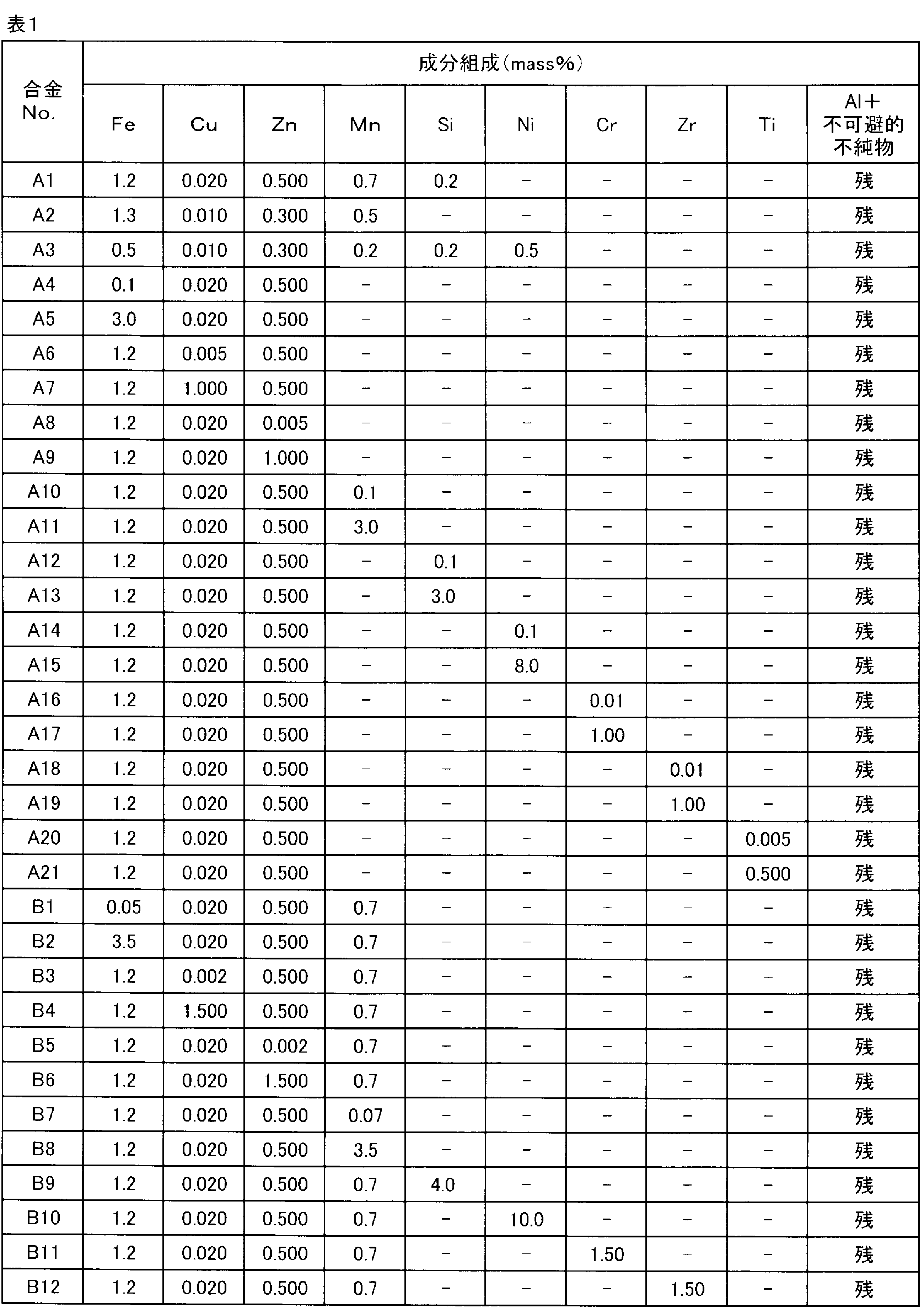
上記のようにして得た円環状アルミニウム合金板に、1.5MPaの圧力下において300℃で3時間の加圧平坦化焼鈍を施しディスクブランクとした。このディスクブランクに表2、3に示す工程を実施してアルミニウム合金基板を作製し,外周面の観察による評価を行った。なお,内外径の切削加工により外径97mm、内径25mmとした。なお、表2、3において、「↑」は上の欄と同じであることを示す。例えば、表2の内径外径加工の場合、C1はその上の欄に記載されるように「外径97mm、内径25mm」であることを示す。そして、C2はC1と同じで「外径97mm、内径25mm」であり、以下同様に、C3~C27も「外径97mm、内径25mm」であることを示す。歪取り加熱処理等においても同様である。
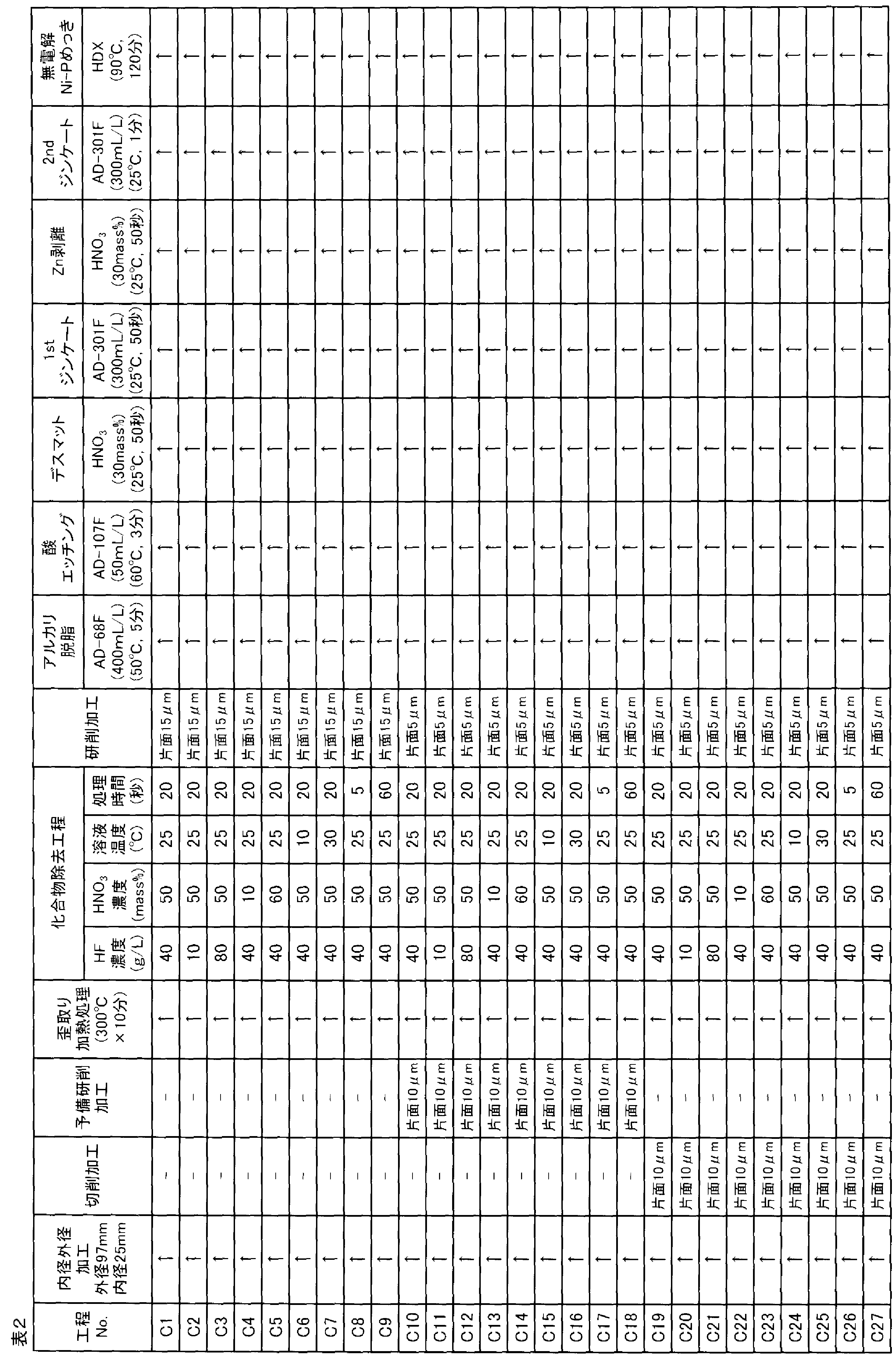

その後、アルミニウム合金基板に、めっき前処理を施した。まず、AD-68F(上村工業製)の濃度400mL/Lにより50℃で5分のアルカリ脱脂を行った後、AD-107F(上村工業製)の濃度50mL/Lにより60℃で3分の酸エッチングを行い、更に室温の30%HNO3水溶液(25℃)で50秒間デスマットを行なった。次いで、25℃ジンケート処理液(AD-301F、上村工業製)の濃度300mL/Lによって50秒間の1stジンケート処理を行った。1stジンケート処理後に、30%HNO3水溶液(25℃)で60秒間ジンケート(Zn)層の剥離を行い、25℃ジンケート処理液(AD-301F、上村工業製)の濃度300mL/Lによって1分間の2ndジンケート処理を再度行った。
2ndジンケート処理を施したアルミニウム合金基板に、90℃の無電解Ni-Pめっき処理液(ニムデンHDX、上村工業製)を用いてNi-Pを14μm厚さに無電解めっきを施し(120分間)、次いで羽布により仕上げ研磨(片面研磨量4μm)を行い、評価用のアルミニウム合金基盤を得た。その後、外周面の観察による評価を行った。
評価1:研削加工後の外周面の観察
めっき前処理直前の研削加工後のアルミニウム合金基板を評価用サンプルとして用い、外周面をデジタルマイクロスコープ(キーエンス製VHX-6000)を用い,2000倍で5視野撮影した。撮影像から、孔の最大径の測定と個数を評価した。5視野の平均から1mm2当たりの孔数を算出し、最大径10μm以上の孔が100個/mm2未満であれば優良(◎)、100個/mm2以上200個/mm2以下であれば良好(○)、200個/mm2より多ければ不良(×)とした。◎と○を合格とし、×を不合格とした。結果を表4、5に示す。
めっき前処理直前の研削加工後のアルミニウム合金基板を評価用サンプルとして用い、外周面をデジタルマイクロスコープ(キーエンス製VHX-6000)を用い,2000倍で5視野撮影した。撮影像から、孔の最大径の測定と個数を評価した。5視野の平均から1mm2当たりの孔数を算出し、最大径10μm以上の孔が100個/mm2未満であれば優良(◎)、100個/mm2以上200個/mm2以下であれば良好(○)、200個/mm2より多ければ不良(×)とした。◎と○を合格とし、×を不合格とした。結果を表4、5に示す。
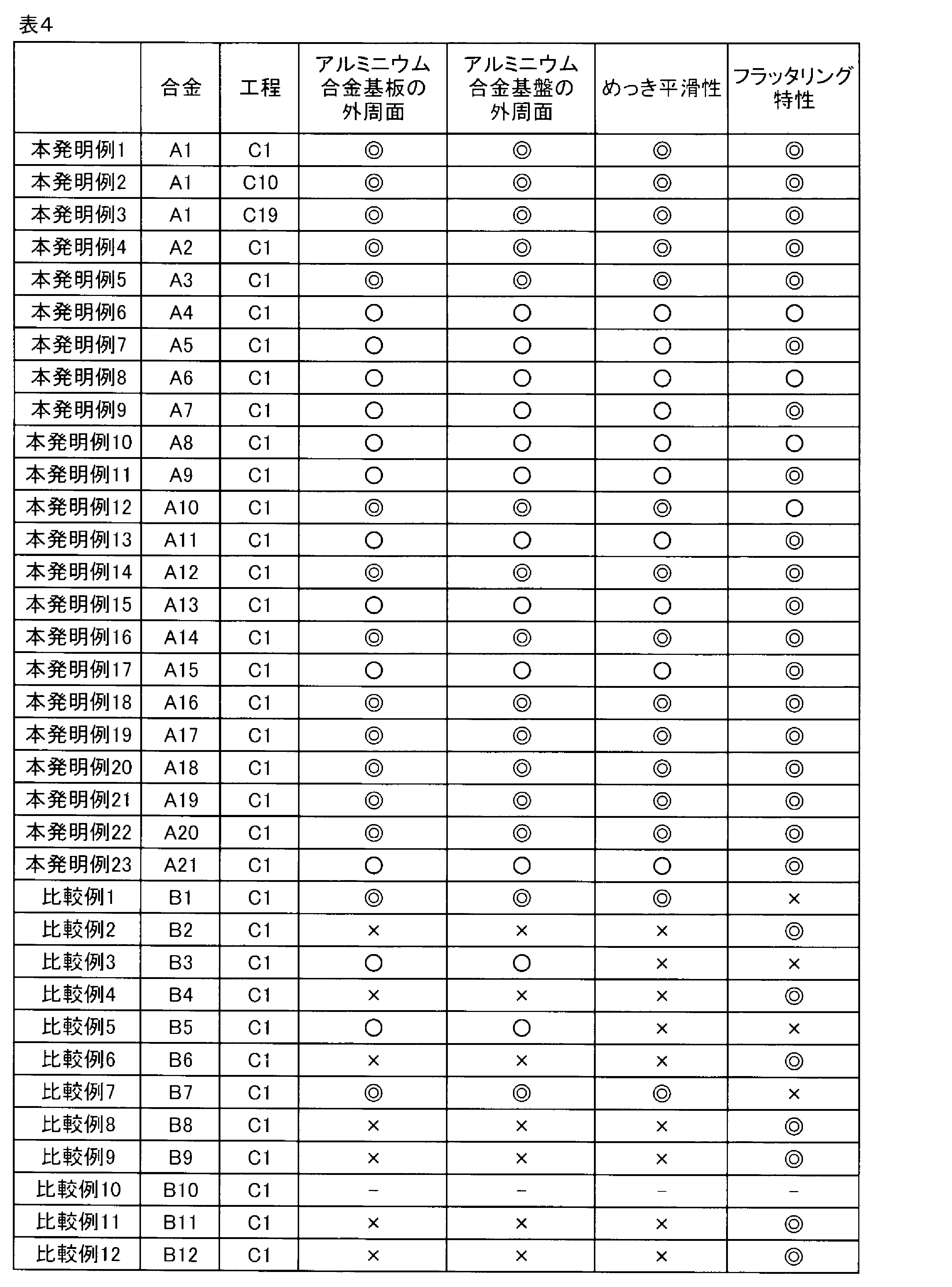

評価2:無電解Ni-Pめっき処理後のアルミニウム合金基盤の外周面の観察
無電解Ni-Pめっき処理後のアルミニウム合金基盤を評価用サンプルとして用い、この外周面をSEMにより1000倍で5視野撮影した。撮影像から、凸部の最大径の測定と個数を評価した。5視野の平均から1mm2当たりの凸部の数を算出し,最大径4~10μmの凸部が150個/mm2未満であれば優良(◎)、150個/mm2以上300個/mm2以下であれば良好(○)、300個/mm2より多ければ不良(×)とした。◎と○を合格とし、×を不合格とした。結果を表4、5に示す。
無電解Ni-Pめっき処理後のアルミニウム合金基盤を評価用サンプルとして用い、この外周面をSEMにより1000倍で5視野撮影した。撮影像から、凸部の最大径の測定と個数を評価した。5視野の平均から1mm2当たりの凸部の数を算出し,最大径4~10μmの凸部が150個/mm2未満であれば優良(◎)、150個/mm2以上300個/mm2以下であれば良好(○)、300個/mm2より多ければ不良(×)とした。◎と○を合格とし、×を不合格とした。結果を表4、5に示す。
評価3:めっき平滑性
無電解Ni-Pめっき後のアルミニウム合金基盤を評価用サンプルとして用い、これを50℃の50vol%硝酸に3分間浸漬して、Ni-Pめっき表面をエッチングした。エッチング後のNi-Pめっき表面を、SEMを用いて5000倍の倍率で5視野撮影した。なお、1視野の面積は536μm2とした。5視野撮影した画像からめっき欠陥数を測定し、5視野の算術平均値を求めた。この算術平均値が、5個未満/視野を優良(◎)、5個以上10個未満/視野を良好(○)、10個以上/視野を不良(×)とした。◎と○を合格とし、×を不合格とした。結果を表4、5に示す。
無電解Ni-Pめっき後のアルミニウム合金基盤を評価用サンプルとして用い、これを50℃の50vol%硝酸に3分間浸漬して、Ni-Pめっき表面をエッチングした。エッチング後のNi-Pめっき表面を、SEMを用いて5000倍の倍率で5視野撮影した。なお、1視野の面積は536μm2とした。5視野撮影した画像からめっき欠陥数を測定し、5視野の算術平均値を求めた。この算術平均値が、5個未満/視野を優良(◎)、5個以上10個未満/視野を良好(○)、10個以上/視野を不良(×)とした。◎と○を合格とし、×を不合格とした。結果を表4、5に示す。
評価4:フラッタリング特性
無電解Ni-Pめっき処理及び表面研磨後のアルミニウム合金基盤を評価用サンプルとして用い、フラッタリング特性を評価した。なお、製品としての磁性体を塗布した磁気ディスクで評価すべきであるが、アルミニウム合金基盤の評価結果が磁気ディスクのものと変わらないことを確認済みである。
無電解Ni-Pめっき処理及び表面研磨後のアルミニウム合金基盤を評価用サンプルとして用い、フラッタリング特性を評価した。なお、製品としての磁性体を塗布した磁気ディスクで評価すべきであるが、アルミニウム合金基盤の評価結果が磁気ディスクのものと変わらないことを確認済みである。
評価用サンプルを、市販のハードディスクドライブに空気の存在下で設置し、測定を行った。ハードディスクドライブはSeagate製ST2000(商品名)を用いて、モーター駆動はテクノアライブ製SLD102(商品名)をモーターに直結することにより駆動させた。回転数は7200rpmとし、ディスクは常に複数枚設置してその上部の磁気ディスクの表面にレーザードップラー計である小野測器製LDV1800(商品名)によって表面の振動を観察した。観察した振動は小野測器製FFT解析装置DS3200(商品名)によってスペクトル分析した。観察はハードディスクドライブの蓋に孔を開け、その孔からディスク表面を観察して行った。また、市販のハードディスクに設置されていたスクイーズプレートは外して評価を行った。
フラッタリング特性の評価は、フラッタリングが現れる300~1500Hzの付近のブロードなピークの最大変位(ディスクフラッタリング(nm))によって行った。このブロードなピークはNRRO(Non-Repeatable Run Out)と呼ばれ、ヘッドの位置決め誤差に対して大きな影響を及ぼすことがわかっている。フラッタリング特性の評価は、空気中にて30nm以下の場合を優良(◎)、30nmを超えて50nm以下の場合を良好(○)、50nmより大きい場合を不良(×)とした。◎と○を合格とし、×を不合格とした。結果を表4、5に示す。
本発明例1~23及び比較例1~12は、アルミニウム合金の組成を変化させた実施例であり、本発明例24~47及び比較例13~23は、アルミニウム合金基板の処理工程を変えた実施例である。
本発明例1~47は、合金組成及び化合物除去工程の条件が本発明範囲内であるので、全ての評価結果が合格となった。
比較例1では、Feの含有量が少ないため第二相粒子が少なく、フラッタリング特性が不合格となった。
比較例2では、Feの含有量が多いため粗大なAl-Fe系化合物が多く、化合物除去工程後の孔が多く、それに伴いNi-Pめっき後の凸部も多かった。その結果、めっき平滑性が不合格となった。
比較例3では、Cuの含有量が少ないため第二相粒子が少なく、フラッタリング特性が不合格となった。また、ジンケート皮膜が不均一であり、めっき表面に欠陥が発生したため、めっき平滑性も不合格となった。
比較例4では、Cuの含有量が多いため粗大なAl-Cu系化合物が多く、化合物除去工程後の孔が多く,それに伴いNi-Pめっき後の凸部も多かった。その結果、めっき平滑性が不合格となった。
比較例5では、Znの含有量が少ないため第二相粒子が少なく、フラッタリング特性が不合格となった。また、ジンケート皮膜が不均一であり、めっき表面に欠陥が発生したため、めっき平滑性も不合格となった。
比較例6では、Znの含有量が多いため母相の電位が卑になり過ぎたため、めっき処理の各工程において母相の溶解が多く凹凸が多数発生した。その結果、Ni-Pめっき後の外周面の凸部及びめっき表面の欠陥が生じ、めっき平滑性が不合格であった。
比較例7では、Mnの含有量が少ないため第二相粒子が少なく、フラッタリング特性が不合格となった。
比較例8では、Mnの含有量が多いため粗大なAl-Mn系化合物が多く、化合物除去工程後の孔が多く、それに伴いNi-Pめっき後の凸部も多かった。その結果、めっき平滑性が不合格となった。
比較例9では、Siの含有量が多いため粗大なSi粒子が多く、化合物除去工程を適用しても除去できなかった。そのため、Ni-Pめっき後の外周面の凸部及びめっき表面の欠陥が生じ、めっき平滑性が不合格であった。
比較例10では、Niの含有量が多いため圧延ができず、評価用サンプルを得ることができなかった。
比較例11では、Crの含有量が多いため粗大なAl-Cr系化合物が多く、化合物除去工程を適用しても除去できなかった。そのため、Ni-Pめっき後の外周面の凸部及びめっき表面の欠陥が生じ、めっき平滑性が不合格であった。
比較例12では,Zrの含有量が多いため粗大なAl-Zr系化合物が多く、化合物除去工程を適用しても除去できなかった。そのため、Ni-Pめっき後の外周面の凸部及びめっき表面の欠陥が生じ、めっき平滑性が不合格であった。
比較例13~15では、化合物除去工程を適用しなかった。その結果、表面は研磨によりめっき平滑性は良好であったが、めっき後の外周面の凸部が多く、ノジュールが多く発生して不合格となった。
比較例16では、化合物除去工程に使用した薬液のHF濃度が低かったため外周面の化合物が十分に除去できず、めっき後の外周面に凸部が多く、ノジュールが多く発生して不合格となった。
比較例17では、化合物除去工程に使用する薬液のHF濃度が高過ぎたため、アルミニウム合金基板の溶解が大きく凹凸が多数発生した。そのため、Ni-Pめっき後の外周面の凸部及びめっき表面の欠陥が生じ、めっき平滑性が不合格であった。
比較例18では、化合物除去工程に使用する薬液のHNO3濃度が低かったため外周面の化合物が十分に除去できず、めっき後の外周面に凸部が多く、ノジュールが多く発生した。また,アルミニウム合金基板の溶解が大きく凹凸が多数発生しめっき表面の欠陥が生じめっき平滑性が不合格となった。
比較例19では、化合物除去工程に使用する薬液のHNO3濃度が高過ぎため外周面の化合物が十分に除去されず、めっき後の外周部端面に凸部が多く、ノジュールが多く発生して不合格となった。
比較例20では,化合物除去工程に使用する薬液の温度が低かったために反応速度が遅く、化合物が十分に除去できず、外周面の化合物が十分に除去できなかった。その結果、めっき後の外周面に凸部が多く、ノジュールが多く発生して不合格となった。
比較例21では、化合物除去工程に使用する薬液の温度が高かったために反応速度が速く、アルミニウム合金基板の溶解が大きく凹凸が多数発生した。その結果、Ni-Pめっき後の外周面の凸部及びめっき表面の欠陥が生じ、めっき平滑性が不合格であった。
比較例22では、化合物除去工程の時間が短かったために反応時間が十分でなく、化合物が十分に除去されておらず、外周面の化合物が十分に除去できなかった。その結果、めっき後の外周面に凸部が多く、ノジュールが多く発生して不合格となった。
比較例23では、化合物除去工程の時間が長かったために反応が進行し過ぎたことにより、アルミニウム基板の溶解が大きく凹凸が多数発生した。その結果、Ni-Pめっき後の外周面の凸部及びめっき表面の欠陥が生じ、めっき平滑性が不合格であった。
2.第2の実施例
本発明例48~94、比較例24~46
この第2の実施例では、アルミニウム合金の鋳造方法に、CC鋳造法を用いた例を示す。
本発明例48~94、比較例24~46
この第2の実施例では、アルミニウム合金の鋳造方法に、CC鋳造法を用いた例を示す。
まず、表1に示す成分組成の各アルミニウム合金を常法に従って溶解し、アルミニウム合金溶湯を溶製した。次に、アルミニウム合金溶湯をCC鋳造法により鋳造し厚さ6mmの薄い鋳造板を作製した。次に、上記鋳造板を、冷間圧延により板厚0.8mmまで圧延して最終圧延板とした。このようにして得たアルミニウム合金板を外径98mm、内径24mmの円環状に打抜き、円環状アルミニウム合金板を作製した。
上記のようにして得た円環状アルミニウム合金板に、1.5MPaの圧力下において300℃で3時間の加圧平坦化焼鈍を施しディスクブランクとした。このディスクブランクに表2、3に示す工程を実施してアルミニウム合金基板を作製し、外周面の観察による評価を行った。なお,内外径の切削加工により外径97mm、内径25mmとした。
その後、アルミニウム合金基板に、めっき前処理を施した。まず、AD-68F(上村工業製)の濃度400mL/Lにより50℃で5分のアルカリ脱脂を行った後、AD-107F(上村工業製)の濃度50mL/Lにより60℃で3分の酸エッチングを行い、更に室温の30%HNO3水溶液(25℃)で50秒間デスマットを行なった。次いで、25℃ジンケート処理液(AD-301F、上村工業製)の濃度300mL/Lによって50秒間の1stジンケート処理を行った。1stジンケート処理後に、30%HNO3水溶液(25℃)で60秒間ジンケート(Zn)層の剥離を行い、25℃ジンケート処理液(AD-301F、上村工業製)の濃度300mL/Lによって1分間の2ndジンケート処理を再度行った。
2ndジンケート処理を施したアルミニウム合金基板に、90℃の無電解Ni-Pめっき処理液(ニムデンHDX、上村工業製)を用いてNi-Pを14μm厚さに無電解めっきを施し(120分間)、次いで羽布により仕上げ研磨(片面研磨量4μm)を行い、評価用のアルミニウム合金基盤を得た。その後、外周面の観察による評価を行った。
評価1:研削加工後の外周面の観察
めっき前処理直前の研削加工後のアルミニウム合金基板を評価用サンプルとして用い、外周面をデジタルマイクロスコープ(キーエンス製VHX-6000)を用い,2000倍で5視野撮影した。撮影像から、孔の最大径の測定と個数を評価した。5視野の平均から1mm2当たりの孔数を算出し、最大径10μm以上の孔が100個/mm2未満であれば優良(◎)、100個/mm2以上200個/mm2以下であれば良好(○)、200個/mm2より多ければ不良(×)とした。◎と○を合格とし、×を不合格とした。結果を表6、7に示す。
めっき前処理直前の研削加工後のアルミニウム合金基板を評価用サンプルとして用い、外周面をデジタルマイクロスコープ(キーエンス製VHX-6000)を用い,2000倍で5視野撮影した。撮影像から、孔の最大径の測定と個数を評価した。5視野の平均から1mm2当たりの孔数を算出し、最大径10μm以上の孔が100個/mm2未満であれば優良(◎)、100個/mm2以上200個/mm2以下であれば良好(○)、200個/mm2より多ければ不良(×)とした。◎と○を合格とし、×を不合格とした。結果を表6、7に示す。
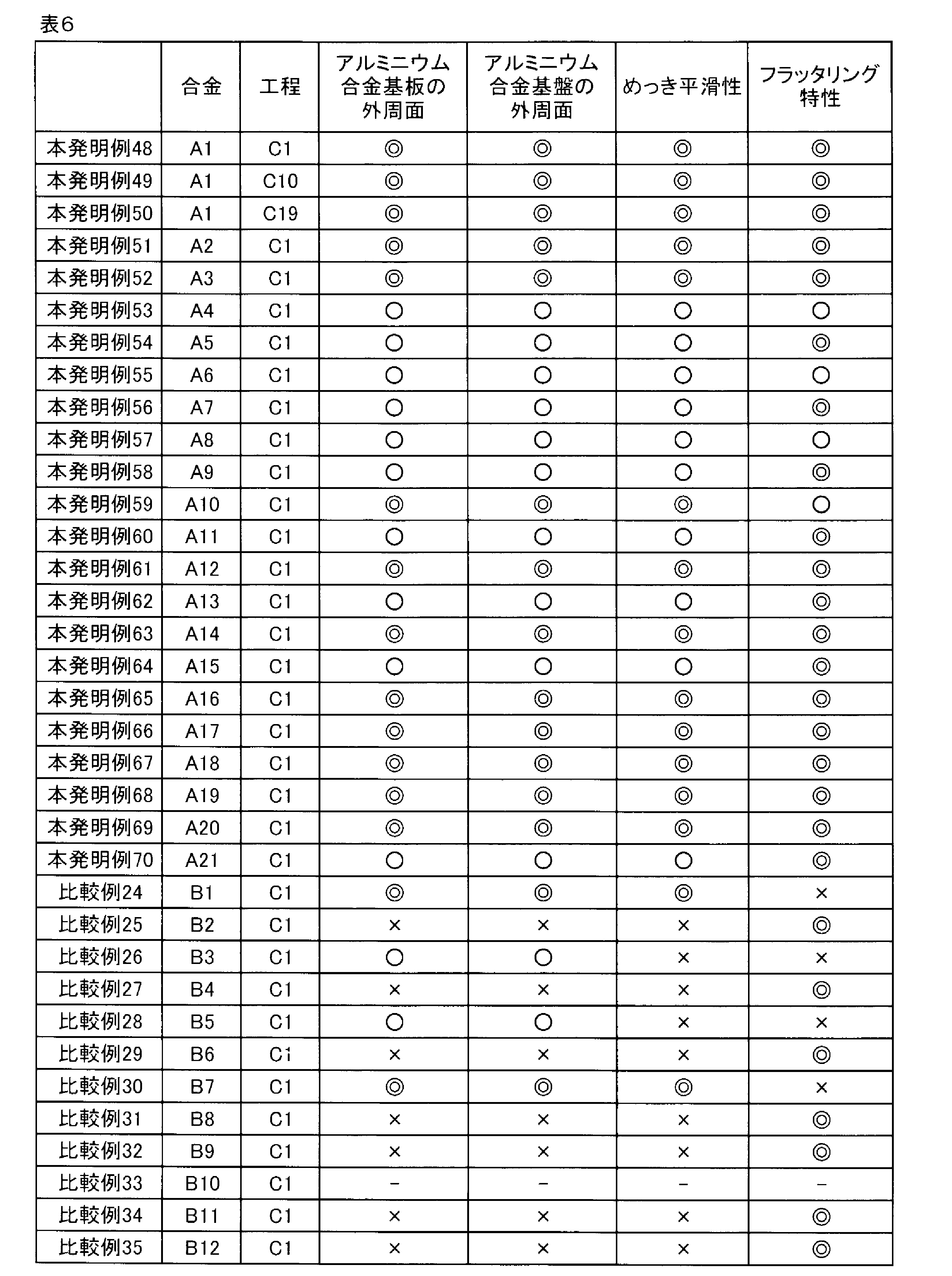

評価2:無電解Ni-Pめっき処理後のアルミニウム合金基盤の外周面の観察
無電解Ni-Pめっき処理後のアルミニウム合金基盤を評価用サンプルとして用い、この外周面をSEMにより1000倍で5視野撮影した。撮影像から、凸部の最大径の測定と個数を評価した。5視野の平均から1mm2当たりの凸部の数を算出し,最大径4~10μmの凸部が150個/mm2未満であれば優良(◎)、150個/mm2以上300個/mm2以下であれば良好(○)、300個/mm2より多ければ不良(×)とした。◎と○を合格とし、×を不合格とした。結果を表6、7に示す。
無電解Ni-Pめっき処理後のアルミニウム合金基盤を評価用サンプルとして用い、この外周面をSEMにより1000倍で5視野撮影した。撮影像から、凸部の最大径の測定と個数を評価した。5視野の平均から1mm2当たりの凸部の数を算出し,最大径4~10μmの凸部が150個/mm2未満であれば優良(◎)、150個/mm2以上300個/mm2以下であれば良好(○)、300個/mm2より多ければ不良(×)とした。◎と○を合格とし、×を不合格とした。結果を表6、7に示す。
評価3:めっき平滑性
無電解Ni-Pめっき後のアルミニウム合金基盤を評価用サンプルとして用い、これを50℃の50vol%硝酸に3分間浸漬して、Ni-Pめっき表面をエッチングした。エッチング後のNi-Pめっき表面を、SEMを用いて5000倍の倍率で5視野撮影した。なお、1視野の面積は536μm2とした。5視野撮影した画像からめっき欠陥数を測定し、5視野の算術平均値を求めた。この算術平均値が、5個未満/視野を優良(◎)、5個以上10個未満/視野を良好(○)、10個以上/視野を不良(×)とした。◎と○を合格とし、×を不合格とした。結果を表6、7に示す。
無電解Ni-Pめっき後のアルミニウム合金基盤を評価用サンプルとして用い、これを50℃の50vol%硝酸に3分間浸漬して、Ni-Pめっき表面をエッチングした。エッチング後のNi-Pめっき表面を、SEMを用いて5000倍の倍率で5視野撮影した。なお、1視野の面積は536μm2とした。5視野撮影した画像からめっき欠陥数を測定し、5視野の算術平均値を求めた。この算術平均値が、5個未満/視野を優良(◎)、5個以上10個未満/視野を良好(○)、10個以上/視野を不良(×)とした。◎と○を合格とし、×を不合格とした。結果を表6、7に示す。
評価4:フラッタリング特性
無電解Ni-Pめっき処理及び表面研磨後のアルミニウム合金基盤を評価用サンプルとして用い、フラッタリング特性を評価した。なお、製品としての磁性体を塗布した磁気ディスクで評価すべきであるが、アルミニウム合金基盤の評価結果が磁気ディスクのものと変わらないことを確認済みである。
無電解Ni-Pめっき処理及び表面研磨後のアルミニウム合金基盤を評価用サンプルとして用い、フラッタリング特性を評価した。なお、製品としての磁性体を塗布した磁気ディスクで評価すべきであるが、アルミニウム合金基盤の評価結果が磁気ディスクのものと変わらないことを確認済みである。
評価用サンプルを、市販のハードディスクドライブに空気の存在下で設置し、測定を行った。ハードディスクドライブはSeagate製ST2000(商品名)を用いて、モーター駆動はテクノアライブ製SLD102(商品名)をモーターに直結することにより駆動させた。回転数は7200rpmとし、ディスクは常に複数枚設置してその上部の磁気ディスクの表面にレーザードップラー計である小野測器製LDV1800(商品名)によって表面の振動を観察した。観察した振動は小野測器製FFT解析装置DS3200(商品名)によってスペクトル分析した。観察はハードディスクドライブの蓋に孔を開け、その孔からディスク表面を観察して行った。また、市販のハードディスクに設置されていたスクイーズプレートは外して評価を行った。
フラッタリング特性の評価は、フラッタリングが現れる300~1500Hzの付近のブロードなピークの最大変位(ディスクフラッタリング(nm))によって行った。このブロードなピークはNRRO(Non-Repeatable Run Out)と呼ばれ、ヘッドの位置決め誤差に対して大きな影響を及ぼすことがわかっている。フラッタリング特性の評価は、空気中にて30nm以下の場合を優良(◎)、30nmを超えて50nm以下の場合を良好(○)、50nmより大きい場合を不良(×)とした。◎と○を合格とし、×を不合格とした。結果を表6、7に示す。
本発明例48~70及び比較例24~35は、アルミニウム合金の組成を変化させた実施例であり、本発明例71~94及び比較例36~46は、アルミニウム合金基板の処理工程を変えた実施例である。
本発明例48~94は、合金組成及び化合物除去工程の条件が本発明範囲内であるので、全ての評価結果が合格となった。
比較例24では、Feの含有量が少ないため第二相粒子が少なく、フラッタリング特性が不合格となった。
比較例25では、Feの含有量が多いため粗大なAl-Fe系化合物が多く、化合物除去工程後の孔が多く、それに伴いNi-Pめっき後の凸部も多かった。その結果、めっき平滑性が不合格となった。
比較例26では、Cuの含有量が少ないため第二相粒子が少なく、フラッタリング特性が不合格となった。また、ジンケート皮膜が不均一であり、めっき表面に欠陥が発生したため、めっき平滑性も不合格となった。
比較例27では、Cuの含有量が多いため粗大なAl-Cu系化合物が多く、化合物除去工程後の孔が多く,それに伴いNi-Pめっき後の凸部も多かった。その結果、めっき平滑性が不合格となった。
比較例28では、Znの含有量が少ないため第二相粒子が少なく、フラッタリング特性が不合格となった。また、ジンケート皮膜が不均一であり、めっき表面に欠陥が発生したため、めっき平滑性も不合格となった。
比較例29では、Znの含有量が多いため母相の電位が卑になり過ぎたため、めっき処理の各工程において母相の溶解が多く凹凸が多数発生した。その結果、Ni-Pめっき後の外周面の凸部及びめっき表面の欠陥が生じ、めっき平滑性が不合格であった。
比較例30では、Mnの含有量が少ないため第二相粒子が少なく、フラッタリング特性が不合格となった。
比較例31では、Mnの含有量が多いため粗大なAl-Mn系化合物が多く、化合物除去工程後の孔が多く、それに伴いNi-Pめっき後の凸部も多かった。その結果、めっき平滑性が不合格となった。
比較例32では、Siの含有量が多いため粗大なSi粒子が多く、化合物除去工程を適用しても除去できなかった。そのため、Ni-Pめっき後の外周面の凸部及びめっき表面の欠陥が生じ、めっき平滑性が不合格であった。
比較例33では、Niの含有量が多いため圧延ができず、評価用サンプルを得ることができなかった。
比較例34では、Crの含有量が多いため粗大なAl-Cr系化合物が多く、化合物除去工程を適用しても除去できなかった。そのため、Ni-Pめっき後の外周面の凸部及びめっき表面の欠陥が生じ、めっき平滑性が不合格であった。
比較例35では,Zrの含有量が多いため粗大なAl-Zr系化合物が多く、化合物除去工程を適用しても除去できなかった。そのため、Ni-Pめっき後の外周面の凸部及びめっき表面の欠陥が生じ、めっき平滑性が不合格であった。
比較例36~38では、化合物除去工程を適用しなかった。その結果、表面は研磨によりめっき平滑性は良好であったが、めっき後の外周面の凸部が多く、ノジュールが多く発生して不合格となった。
比較例39では、化合物除去工程に使用した薬液のHF濃度が低かったため外周面の化合物が十分に除去できず、めっき後の外周面に凸部が多く、ノジュールが多く発生して不合格となった。
比較例40では、化合物除去工程に使用する薬液のHF濃度が高過ぎたため、アルミニウム合金基板の溶解が大きく凹凸が多数発生した。そのため、Ni-Pめっき後の外周面の凸部及びめっき表面の欠陥が生じ、めっき平滑性が不合格であった。
比較例41では、化合物除去工程に使用する薬液のHNO3濃度が低かったため外周面の化合物が十分に除去できず、めっき後の外周面に凸部が多く、ノジュールが多く発生した。また,アルミニウム合金基板の溶解が大きく凹凸が多数発生しめっき表面の欠陥が生じめっき平滑性が不合格となった。
比較例42では、化合物除去工程に使用する薬液のHNO3濃度が高過ぎため外周面の化合物が十分に除去されず、めっき後の外周部端面に凸部が多く、ノジュールが多く発生して不合格となった。
比較例43では,化合物除去工程に使用する薬液の温度が低かったために反応速度が遅く、化合物が十分に除去できず、外周面の化合物が十分に除去できなかった。その結果、めっき後の外周面に凸部が多く、ノジュールが多く発生して不合格となった。
比較例44では、化合物除去工程に使用する薬液の温度が高かったために反応速度が速く、アルミニウム合金基板の溶解が大きく凹凸が多数発生した。その結果、Ni-Pめっき後の外周面の凸部及びめっき表面の欠陥が生じ、めっき平滑性が不合格であった。
比較例45では、化合物除去工程の時間が短かったために反応時間が十分でなく、化合物が十分に除去されておらず、外周面の化合物が十分に除去できなかった。その結果、めっき後の外周面に凸部が多く、ノジュールが多く発生して不合格となった。
比較例46では、化合物除去工程の時間が長かったために反応が進行し過ぎたことにより、アルミニウム合金基板の溶解が大きく凹凸が多数発生した。その結果、Ni-Pめっき後の外周面の凸部及びめっき表面の欠陥が生じ、めっき平滑性が不合格であった。
ディスクフラッタが低減され、且つ、無電解Ni-Pめっき表面の欠陥が低減されるという特徴を有する磁気ディスク用アルミニウム合金基盤の提供により、磁気ディスクの薄肉化による搭載枚数の増加と1枚当たりの記憶容量の増加を可能とし、HDDの高容量化に寄与する磁気ディスクを提供できる。
Claims (13)
- Fe:0.1~3.0mass%、Cu:0.005~1.000mass%、Zn:0.005~1.000mass%を含有し、残部Al及び不可避不純物からなるアルミニウム合金からなり、外周面において、最長径10μm以上の孔が200個/mm2以下であることを特徴とする磁気ディスク用アルミニウム合金基板。
- 前記アルミニウム合金が、Mn:0.1~3.0mass%、Si:0.1~3.0mass%、Ni:0.1~8.0mass%、Cr:0.01~1.00mass%及びZr:0.01~1.00mass%から選択される1種又は2種以上を更に含有する、請求項1に記載の磁気ディスク用アルミニウム合金基板。
- 前記アルミニウム合金が、合計の含有量が0.005~0.500mass%であるTi、B及びVから選択される1種又は2種以上を更に含有する、請求項1又は2に記載の磁気ディスク用アルミニウム合金基板。
- 請求項1~3のいずれか一項に記載の磁気ディスク用アルミニウム合金基板表面に無電解Ni-Pめっき層を備える磁気ディスク用アルミニウム合金基盤であって、外周面において、最長径4~10μmの凸部が300個/mm2以下であることを特徴とする磁気ディスク用アルミニウム合金基盤。
- 請求項4に記載の磁気ディスク用アルミニウム合金基盤の表面に磁性体層を備えることを特徴とする磁気ディスク。
- 請求項1~3のいずれか一項に記載される磁気ディスク用アルミニウム合金基板の製造方法であって、前記アルミニウム合金を用いて鋳塊を半連続鋳造する半連続鋳造工程と、鋳塊を熱間圧延する熱間圧延工程と、熱間圧延板を冷間圧延する冷間圧延工程と、冷間圧延板を円環状に打ち抜くディスクブランク打抜き工程と、打ち抜いたディスクブランクを加圧焼鈍する加圧平坦化焼鈍工程と、加圧焼鈍したディスクブランクの内周面及び外周面を加工する内径外径加工工程と、内径外径加工を施したディスクブランクに歪取り加熱を施す歪取り加熱処理工程と、歪取り加熱処理を施したディスクブランク表面の化合物を除去する化合物除去工程と、化合物除去を施したディスクブランクに研削加工を施す研削工程とを備え、前記化合物除去工程が、10~30℃の10~60mass%のHNO3溶液であって10~80g/LのHFを含有するHNO3/HFの混合溶液にディスクブランクを5~60秒浸漬することを特徴とする磁気ディスク用アルミニウム合金基板の製造方法。
- 請求項1~3のいずれか一項に記載される磁気ディスク用アルミニウム合金基板の製造方法であって、前記アルミニウム合金を用いて鋳塊を半連続鋳造する半連続鋳造工程と、鋳塊を熱間圧延する熱間圧延工程と、熱間圧延板を冷間圧延する冷間圧延工程と、冷間圧延板を円環状に打ち抜くディスクブランク打抜き工程と、打ち抜いたディスクブランクを加圧焼鈍する加圧平坦化焼鈍工程と、加圧焼鈍したディスクブランクの内周面及び外周面を加工する内径外径加工工程と、内径外径加工を施したディスクブランクに予備研削加工を施す予備研削工程と、予備研削加工を施したディスクブランクに歪取り加熱を施す歪取り加熱処理工程と、歪取り加熱処理を施したディスクブランク表面の化合物を除去する化合物除去工程と、化合物除去を施したディスクブランクに研削加工を施す研削工程とを備え、前記化合物除去工程が、10~30℃の10~60mass%のHNO3溶液であって10~80g/LのHFを含有するHNO3/HFの混合溶液にディスクブランクを5~60秒浸漬することを特徴とする磁気ディスク用アルミニウム合金基板の製造方法。
- 請求項1~3のいずれか一項に記載される磁気ディスク用アルミニウム合金基板の製造方法であって、前記アルミニウム合金を用いて鋳塊を半連続鋳造する半連続鋳造工程と、鋳塊を熱間圧延する熱間圧延工程と、熱間圧延板を冷間圧延する冷間圧延工程と、冷間圧延板を円環状に打ち抜くディスクブランク打抜き工程と、打ち抜いたディスクブランクを加圧焼鈍する加圧平坦化焼鈍工程と、加圧焼鈍したディスクブランクの内周面及び外周面を加工する内径外径加工工程と、内径外径加工を施したディスクブランクに切削加工を施す切削工程と、切削加工を施したディスクブランクに歪取り加熱を施す歪取り加熱処理工程と、歪取り加熱処理を施したディスクブランク表面の化合物を除去する化合物除去工程と、化合物除去を施したディスクブランクに研削加工を施す研削工程とを備え、前記化合物除去工程が、10~30℃の10~60mass%のHNO3溶液であって10~80g/LのHFを含有するHNO3/HFの混合溶液にディスクブランクを5~60秒浸漬することを特徴とする磁気ディスク用アルミニウム合金基板の製造方法。
- 請求項1~3のいずれか一項に記載される磁気ディスク用アルミニウム合金基板の製造方法であって、前記アルミニウム合金を用いて鋳塊を連続鋳造する連続鋳造工程と、鋳塊を冷間圧延する冷間圧延工程と、冷間圧延板を円環状に打ち抜くディスクブランク打抜き工程と、打ち抜いたディスクブランクを加圧焼鈍する加圧平坦化焼鈍工程と、加圧焼鈍したディスクブランクの内周面及び外周面を加工する内径外径加工工程と、内径外径加工を施したディスクブランクに歪取り加熱を施す歪取り加熱処理工程と、歪取り加熱処理を施したディスクブランク表面の化合物を除去する化合物除去工程と、化合物除去を施したディスクブランクに研削加工を施す研削工程とを備え、前記化合物除去工程が、10~30℃の10~60mass%のHNO3溶液であって10~80g/LのHFを含有するHNO3/HFの混合溶液にディスクブランクを5~60秒浸漬することを特徴とする磁気ディスク用アルミニウム合金基板の製造方法。
- 請求項1~3のいずれか一項に記載される磁気ディスク用アルミニウム合金基板の製造方法であって、前記アルミニウム合金を用いて鋳塊を連続鋳造する連続鋳造工程と、鋳塊を冷間圧延する冷間圧延工程と、冷間圧延板を円環状に打ち抜くディスクブランク打抜き工程と、打ち抜いたディスクブランクを加圧焼鈍する加圧平坦化焼鈍工程と、加圧焼鈍したディスクブランクの内周面及び外周面を加工する内径外径加工工程と、内径外径加工を施したディスクブランクに予備研削加工を施す予備研削工程と、予備研削加工を施したディスクブランクに歪取り加熱を施す歪取り加熱処理工程と、歪取り加熱処理を施したディスクブランク表面の化合物を除去する化合物除去工程と、化合物除去を施したディスクブランクに研削加工を施す研削工程とを備え、前記化合物除去工程が、10~30℃の10~60mass%のHNO3溶液であって10~80g/LのHFを含有するHNO3/HFの混合溶液にディスクブランクを5~60秒浸漬することを特徴とする磁気ディスク用アルミニウム合金基板の製造方法。
- 請求項1~3のいずれか一項に記載される磁気ディスク用アルミニウム合金基板の製造方法であって、前記アルミニウム合金を用いて鋳塊を連続鋳造する連続鋳造工程と、鋳塊を冷間圧延する冷間圧延工程と、冷間圧延板を円環状に打ち抜くディスクブランク打抜き工程と、打ち抜いたディスクブランクを加圧焼鈍する加圧平坦化焼鈍工程と、加圧焼鈍したディスクブランクの内周面及び外周面を加工する内径外径加工工程と、内径外径加工を施したディスクブランクに切削加工を施す切削工程と、切削加工を施したディスクブランクに歪取り加熱を施す歪取り加熱処理工程と、歪取り加熱処理を施したディスクブランク表面の化合物を除去する化合物除去工程と、化合物除去を施したディスクブランクに研削加工を施す研削工程とを備え、前記化合物除去工程が、10~30℃の10~60mass%のHNO3溶液であって10~80g/LのHFを含有するHNO3/HFの混合溶液にディスクブランクを5~60秒浸漬することを特徴とする磁気ディスク用アルミニウム合金基板の製造方法。
- 請求項4に記載される磁気ディスク用アルミニウム合金基盤の製造方法であって、請求項6~11のいずれか一項に記載の磁気ディスク用アルミニウム合金基板の製造方法において、前記研削工程後に、ディスクブランクのアルカリ脱脂処理段階、酸エッチング処理段階、デスマット処理段階及びジンケート処理段階をこの順序で含むめっき前処理工程と、当該めっき前処理工程を施したディスクブランク表面に無電解Ni-Pめっき処理を施す無電解Ni-Pめっき処理工程とを備えることを特徴とする磁気ディスク用アルミニウム合金基盤の製造方法。
- 請求項5に記載される磁気ディスクの製造方法であって、請求項4に記載される磁気ディスク用アルミニウム合金基盤の表面を研磨し、この研磨表面に、磁性体層をスパッタリングによって付着させることを特徴とする磁気ディスクの製造方法。
Priority Applications (3)
| Application Number | Priority Date | Filing Date | Title |
|---|---|---|---|
| CN201980076852.XA CN113168848A (zh) | 2018-11-26 | 2019-10-25 | 磁盘用铝合金基板及其制造方法、磁盘用铝合金基盘及其制造方法、以及磁盘及其制造方法 |
| MYPI2021002769A MY188247A (en) | 2018-11-26 | 2019-10-25 | Aluminum alloy substrate for magnetic disk and method for manufacturing same, aluminum alloy base disk for magnetic disk and method for manufacturing same, and magnetic disk and method for manufacturing same |
| US17/296,610 US11482251B2 (en) | 2018-11-26 | 2019-10-25 | Aluminum alloy substrate for magnetic disk and method for manufacturing same, aluminum alloy base disk for magnetic disk and method for manufacturing same, and magnetic disk and method for manufacturing the same |
Applications Claiming Priority (2)
| Application Number | Priority Date | Filing Date | Title |
|---|---|---|---|
| JP2018220750A JP6506898B1 (ja) | 2018-11-26 | 2018-11-26 | 磁気ディスク用アルミニウム合金基板及びその製造方法、磁気ディスク用アルミニウム合金基盤及びその製造方法、ならびに、磁気ディスク及びその製造方法 |
| JP2018-220750 | 2018-11-26 |
Publications (1)
| Publication Number | Publication Date |
|---|---|
| WO2020110544A1 true WO2020110544A1 (ja) | 2020-06-04 |
Family
ID=66324142
Family Applications (1)
| Application Number | Title | Priority Date | Filing Date |
|---|---|---|---|
| PCT/JP2019/041970 Ceased WO2020110544A1 (ja) | 2018-11-26 | 2019-10-25 | 磁気ディスク用アルミニウム合金基板及びその製造方法、磁気ディスク用アルミニウム合金基盤及びその製造方法、ならびに、磁気ディスク及びその製造方法 |
Country Status (5)
| Country | Link |
|---|---|
| US (1) | US11482251B2 (ja) |
| JP (1) | JP6506898B1 (ja) |
| CN (1) | CN113168848A (ja) |
| MY (1) | MY188247A (ja) |
| WO (1) | WO2020110544A1 (ja) |
Cited By (1)
| Publication number | Priority date | Publication date | Assignee | Title |
|---|---|---|---|---|
| JP2022090912A (ja) * | 2020-12-08 | 2022-06-20 | 株式会社Uacj | 磁気ディスク基板および磁気ディスク |
Citations (6)
| Publication number | Priority date | Publication date | Assignee | Title |
|---|---|---|---|---|
| JPS642229B2 (ja) * | 1980-08-07 | 1989-01-17 | Nippon Electric Co | |
| JPH09235640A (ja) * | 1996-02-28 | 1997-09-09 | Furukawa Electric Co Ltd:The | 磁気ディスク基板用アルミニウム合金板及びその製造方法 |
| JPH11175963A (ja) * | 1997-12-04 | 1999-07-02 | Kobe Steel Ltd | 磁気ディスク用アルミニウム合金基板及び磁気ディスク |
| JP2006302358A (ja) * | 2005-04-18 | 2006-11-02 | Kobe Steel Ltd | 磁気記録媒体用Al合金基板および磁気記録媒体 |
| JP2017110273A (ja) * | 2015-12-17 | 2017-06-22 | 株式会社Uacj | 磁気ディスク基板用アルミニウム合金基板及びその製造方法、ならびに、当該アルミニウム合金基板を用いた磁気ディスクの製造方法 |
| WO2018155237A1 (ja) * | 2017-02-27 | 2018-08-30 | 株式会社Uacj | 磁気ディスク用アルミニウム合金基板及びその製造方法、ならびに、この磁気ディスク用アルミニウム合金基板を用いた磁気ディスク |
Family Cites Families (11)
| Publication number | Priority date | Publication date | Assignee | Title |
|---|---|---|---|---|
| JPS60194040A (ja) * | 1984-02-18 | 1985-10-02 | Kobe Steel Ltd | メツキ性に優れたデイスク用アルミニウム合金板 |
| JPH0430325A (ja) * | 1990-05-25 | 1992-02-03 | Yamaha Corp | 磁気ディスク基板の製法 |
| US5939164A (en) | 1996-02-28 | 1999-08-17 | The Furukawa Electric Co., Ltd. | Aluminum alloy sheet for magnetic disk substrate aluminum alloy clad sheet for magnetic disk substrate and their manufacturing method |
| JP5872322B2 (ja) | 2012-02-24 | 2016-03-01 | 株式会社Uacj | 磁気ディスク用基板の製造方法、磁気ディスク用基板、磁気ディスク、磁気ディスク基板用洗浄剤 |
| JP5973952B2 (ja) * | 2013-04-19 | 2016-08-23 | 株式会社神戸製鋼所 | 磁気ディスク用アルミニウム合金基板およびその製造方法 |
| MY182369A (en) | 2014-10-31 | 2021-01-21 | Uacj Corp | Aluminum alloy substrate for magnetic disk |
| WO2017188320A1 (ja) * | 2016-04-27 | 2017-11-02 | 株式会社Uacj | 磁気ディスク用基板 |
| MY176367A (en) | 2017-02-01 | 2020-08-04 | Furukawa Electric Co Ltd | Aluminum alloy magnetic disk substrate and method for producing same |
| JP6389546B1 (ja) * | 2017-05-12 | 2018-09-12 | 株式会社Uacj | 磁気ディスク用アルミニウム合金基板及びその製造方法、ならびに、この磁気ディスク用アルミニウム合金基板を用いた磁気ディスク |
| JP6402229B1 (ja) * | 2017-09-28 | 2018-10-10 | 株式会社Uacj | 磁気ディスク用アルミニウム合金基板及びその製造方法、ならびに、当該磁気ディスク用アルミニウム合金基板を用いた磁気ディスク |
| JP6439064B1 (ja) * | 2018-02-23 | 2018-12-19 | 株式会社Uacj | 磁気ディスク、並びに、磁気ディスク用のアルミニウム合基板及び該アルミニウム合金基板の製造方法 |
-
2018
- 2018-11-26 JP JP2018220750A patent/JP6506898B1/ja active Active
-
2019
- 2019-10-25 WO PCT/JP2019/041970 patent/WO2020110544A1/ja not_active Ceased
- 2019-10-25 MY MYPI2021002769A patent/MY188247A/en unknown
- 2019-10-25 US US17/296,610 patent/US11482251B2/en active Active
- 2019-10-25 CN CN201980076852.XA patent/CN113168848A/zh active Pending
Patent Citations (6)
| Publication number | Priority date | Publication date | Assignee | Title |
|---|---|---|---|---|
| JPS642229B2 (ja) * | 1980-08-07 | 1989-01-17 | Nippon Electric Co | |
| JPH09235640A (ja) * | 1996-02-28 | 1997-09-09 | Furukawa Electric Co Ltd:The | 磁気ディスク基板用アルミニウム合金板及びその製造方法 |
| JPH11175963A (ja) * | 1997-12-04 | 1999-07-02 | Kobe Steel Ltd | 磁気ディスク用アルミニウム合金基板及び磁気ディスク |
| JP2006302358A (ja) * | 2005-04-18 | 2006-11-02 | Kobe Steel Ltd | 磁気記録媒体用Al合金基板および磁気記録媒体 |
| JP2017110273A (ja) * | 2015-12-17 | 2017-06-22 | 株式会社Uacj | 磁気ディスク基板用アルミニウム合金基板及びその製造方法、ならびに、当該アルミニウム合金基板を用いた磁気ディスクの製造方法 |
| WO2018155237A1 (ja) * | 2017-02-27 | 2018-08-30 | 株式会社Uacj | 磁気ディスク用アルミニウム合金基板及びその製造方法、ならびに、この磁気ディスク用アルミニウム合金基板を用いた磁気ディスク |
Cited By (1)
| Publication number | Priority date | Publication date | Assignee | Title |
|---|---|---|---|---|
| JP2022090912A (ja) * | 2020-12-08 | 2022-06-20 | 株式会社Uacj | 磁気ディスク基板および磁気ディスク |
Also Published As
| Publication number | Publication date |
|---|---|
| JP6506898B1 (ja) | 2019-04-24 |
| US11482251B2 (en) | 2022-10-25 |
| CN113168848A (zh) | 2021-07-23 |
| MY188247A (en) | 2021-11-24 |
| JP2020087494A (ja) | 2020-06-04 |
| US20210358520A1 (en) | 2021-11-18 |
Similar Documents
| Publication | Publication Date | Title |
|---|---|---|
| JP6439082B1 (ja) | アルミニウム合金製の磁気ディスク基板及びその製造方法 | |
| JP6389546B1 (ja) | 磁気ディスク用アルミニウム合金基板及びその製造方法、ならびに、この磁気ディスク用アルミニウム合金基板を用いた磁気ディスク | |
| CN111771241B (zh) | 磁盘用铝合金基板及其制造方法、以及使用该磁盘用铝合金基板的磁盘 | |
| JP6439064B1 (ja) | 磁気ディスク、並びに、磁気ディスク用のアルミニウム合基板及び該アルミニウム合金基板の製造方法 | |
| CN111164228B (zh) | 磁盘用铝合金基板及其制造方法、以及使用该磁盘用铝合金基板的磁盘 | |
| CN111212927A (zh) | 磁盘用铝合金基板及其制造方法、以及使用该磁盘用铝合金基板的磁盘 | |
| CN111886648B (zh) | 磁盘基板及其制造方法以及磁盘 | |
| CN112840399B (zh) | 磁盘用铝合金板及其制造方法,以及使用该磁盘用铝合金板的磁盘 | |
| JP7027210B2 (ja) | 磁気ディスク用アルミニウム合金板及びその製造方法、ならびに、当該磁気ディスク用アルミニウム合金板を用いた磁気ディスク | |
| WO2020022380A1 (ja) | 磁気ディスク用アルミニウム合金板及びその製造方法、ならびに、この磁気ディスク用アルミニウム合金板を用いた磁気ディスク | |
| WO2020110544A1 (ja) | 磁気ディスク用アルミニウム合金基板及びその製造方法、磁気ディスク用アルミニウム合金基盤及びその製造方法、ならびに、磁気ディスク及びその製造方法 | |
| JP3710009B2 (ja) | 磁気ディスク基板用アルミニウム合金板及びその製造方法 | |
| JP2020007624A (ja) | 磁気ディスク用アルミニウム合金基板及びその製造方法、ならびに、当該磁気ディスク用アルミニウム合金基板を用いた磁気ディスク | |
| JP2018005968A (ja) | 磁気ディスク用基板および磁気ディスク用基板の製造方法 | |
| JP7145731B2 (ja) | 磁気ディスク用ブランク材及びその製造方法 | |
| JPH0752030A (ja) | 陽極酸化処理基盤及び研磨方法 |
Legal Events
| Date | Code | Title | Description |
|---|---|---|---|
| 121 | Ep: the epo has been informed by wipo that ep was designated in this application |
Ref document number: 19889888 Country of ref document: EP Kind code of ref document: A1 |
|
| NENP | Non-entry into the national phase |
Ref country code: DE |
|
| 122 | Ep: pct application non-entry in european phase |
Ref document number: 19889888 Country of ref document: EP Kind code of ref document: A1 |