WO2020110423A1 - グラブボックスロック装置 - Google Patents
グラブボックスロック装置 Download PDFInfo
- Publication number
- WO2020110423A1 WO2020110423A1 PCT/JP2019/035823 JP2019035823W WO2020110423A1 WO 2020110423 A1 WO2020110423 A1 WO 2020110423A1 JP 2019035823 W JP2019035823 W JP 2019035823W WO 2020110423 A1 WO2020110423 A1 WO 2020110423A1
- Authority
- WO
- WIPO (PCT)
- Prior art keywords
- knob
- glove box
- arm
- shaft portion
- spring
- Prior art date
- Legal status (The legal status is an assumption and is not a legal conclusion. Google has not performed a legal analysis and makes no representation as to the accuracy of the status listed.)
- Ceased
Links
Images



Classifications
-
- E—FIXED CONSTRUCTIONS
- E05—LOCKS; KEYS; WINDOW OR DOOR FITTINGS; SAFES
- E05B—LOCKS; ACCESSORIES THEREFOR; HANDCUFFS
- E05B83/00—Vehicle locks specially adapted for particular types of wing or vehicle
- E05B83/28—Locks for glove compartments, console boxes, fuel inlet covers or the like
- E05B83/30—Locks for glove compartments, console boxes, fuel inlet covers or the like for glove compartments
-
- B—PERFORMING OPERATIONS; TRANSPORTING
- B60—VEHICLES IN GENERAL
- B60R—VEHICLES, VEHICLE FITTINGS, OR VEHICLE PARTS, NOT OTHERWISE PROVIDED FOR
- B60R7/00—Stowing or holding appliances inside vehicle primarily intended for personal property smaller than suit-cases, e.g. travelling articles, or maps
- B60R7/04—Stowing or holding appliances inside vehicle primarily intended for personal property smaller than suit-cases, e.g. travelling articles, or maps in driver or passenger space, e.g. using racks
- B60R7/06—Stowing or holding appliances inside vehicle primarily intended for personal property smaller than suit-cases, e.g. travelling articles, or maps in driver or passenger space, e.g. using racks mounted on or below dashboards
-
- E—FIXED CONSTRUCTIONS
- E05—LOCKS; KEYS; WINDOW OR DOOR FITTINGS; SAFES
- E05C—BOLTS OR FASTENING DEVICES FOR WINGS, SPECIALLY FOR DOORS OR WINDOWS
- E05C1/00—Fastening devices with bolts moving rectilinearly
- E05C1/08—Fastening devices with bolts moving rectilinearly with latching action
- E05C1/12—Fastening devices with bolts moving rectilinearly with latching action with operating handle or equivalent member moving otherwise than rigidly with the latch
-
- E—FIXED CONSTRUCTIONS
- E05—LOCKS; KEYS; WINDOW OR DOOR FITTINGS; SAFES
- E05C—BOLTS OR FASTENING DEVICES FOR WINGS, SPECIALLY FOR DOORS OR WINDOWS
- E05C9/00—Arrangements of simultaneously actuated bolts or other securing devices at well-separated positions on the same wing
- E05C9/04—Arrangements of simultaneously actuated bolts or other securing devices at well-separated positions on the same wing with two sliding bars moved in opposite directions when fastening or unfastening
-
- E—FIXED CONSTRUCTIONS
- E05—LOCKS; KEYS; WINDOW OR DOOR FITTINGS; SAFES
- E05C—BOLTS OR FASTENING DEVICES FOR WINGS, SPECIALLY FOR DOORS OR WINDOWS
- E05C9/00—Arrangements of simultaneously actuated bolts or other securing devices at well-separated positions on the same wing
- E05C9/08—Arrangements of simultaneously actuated bolts or other securing devices at well-separated positions on the same wing with a rotary bar for actuating the fastening means
- E05C9/085—Arrangements of simultaneously actuated bolts or other securing devices at well-separated positions on the same wing with a rotary bar for actuating the fastening means pivoting about an axis perpendicular to the door
-
- E—FIXED CONSTRUCTIONS
- E05—LOCKS; KEYS; WINDOW OR DOOR FITTINGS; SAFES
- E05B—LOCKS; ACCESSORIES THEREFOR; HANDCUFFS
- E05B15/00—Other details of locks; Parts for engagement by bolts of fastening devices
- E05B15/04—Spring arrangements in locks
- E05B2015/0403—Wound springs
- E05B2015/0406—Wound springs wound in a cylindrical shape
- E05B2015/041—Wound springs wound in a cylindrical shape loaded perpendicular to cylinder axis
-
- E—FIXED CONSTRUCTIONS
- E05—LOCKS; KEYS; WINDOW OR DOOR FITTINGS; SAFES
- E05B—LOCKS; ACCESSORIES THEREFOR; HANDCUFFS
- E05B15/00—Other details of locks; Parts for engagement by bolts of fastening devices
- E05B15/04—Spring arrangements in locks
- E05B2015/0496—Springs actuated by cams or the like
-
- E—FIXED CONSTRUCTIONS
- E05—LOCKS; KEYS; WINDOW OR DOOR FITTINGS; SAFES
- E05C—BOLTS OR FASTENING DEVICES FOR WINGS, SPECIALLY FOR DOORS OR WINDOWS
- E05C1/00—Fastening devices with bolts moving rectilinearly
- E05C1/004—Fastening devices with bolts moving rectilinearly parallel to the surface on which the fastener is mounted
-
- E—FIXED CONSTRUCTIONS
- E05—LOCKS; KEYS; WINDOW OR DOOR FITTINGS; SAFES
- E05C—BOLTS OR FASTENING DEVICES FOR WINGS, SPECIALLY FOR DOORS OR WINDOWS
- E05C9/00—Arrangements of simultaneously actuated bolts or other securing devices at well-separated positions on the same wing
- E05C9/04—Arrangements of simultaneously actuated bolts or other securing devices at well-separated positions on the same wing with two sliding bars moved in opposite directions when fastening or unfastening
- E05C9/043—Arrangements of simultaneously actuated bolts or other securing devices at well-separated positions on the same wing with two sliding bars moved in opposite directions when fastening or unfastening with crank pins and connecting rods
Definitions
- the present invention relates to a glove box lock device mounted on a vehicle, for example.
- the grab box lock device includes a base member, a knob member, a dog member, and a spring member.
- the base member is attached to the glove box.
- the knob member is a member that is arranged on the front side of the glove box and that can be opened by an operator, and is supported by the base member so as to be rotatable between a closed position and an open position.
- the knob member is locked to the dog member.
- the dog member is movably attached to the base member between an engagement position where the striker on the glove box side is engaged and an engagement release position where the engagement is released.
- the spring member is supported and fixed to the base member at the center, is locked to the knob member at one end, and is locked to the dog member at the other end.
- the knob member is biased to the closed position on one end side from the central part of the spring member, and the dog member is biased to the engagement position on the other end side from the central part of the spring member.
- the knob member and the dog member are individually and independently biased to the closed position or the engaged position by using one spring member.
- the knob member is regulated to a predetermined closed position and fixed in position with an urging force applied from one end side of the spring member.
- the dog member is regulated and fixed in position at a predetermined engagement position in a state in which a biasing force is applied from the other end side of the spring member.
- the biasing force applied to the knob member from the spring member in the direction of the closed position becomes large. It is possible to get out. Further, since the biasing force applied from the spring member to the dog member in the engaging position direction becomes large, the dog member is engaged after the opening operation of the knob member is released after the dog member is moved to the engagement releasing position. It is possible to realize the operation of automatically restoring from the disengagement position to the engagement position. Further, when the glove box is closed from the open state, even if the dog member moves from the engaged position to the disengaged position due to contact with the striker, the dog member is immediately engaged by the biasing force of the spring member. Since the knob member is returned from the mating release position to the engagement position, it is possible to prevent the knob member from rotating toward the open position side, which prevents rattling of the knob member when the glove box transitions from the open door to the closed door. Can be prevented.
- the present invention has been made in view of the above circumstances, and an object thereof is to provide a glove box lock device capable of reducing the number of assembling steps while realizing a desired lock function with a single spring member.
- One aspect of the present invention is a base member that is attached to a glove box and has a shaft portion that extends in a predetermined direction, and a base member that is disposed on the front side of the glove box and that has a closed position and an open position around the shaft portion.
- a knob member that is rotatably supported between the knob member and a lock position that is swingably supported by the base member at the center in the longitudinal direction and abuts the knob member at one end to lock the glove box.
- An arm member that swings between an unlocking position for unlocking the glove box and a shaft externally rotatably inserted in the shaft portion, locked at one end by the knob member, and at the other end by the arm.
- a spring member that is locked to the other end of the member and that generates a biasing force that rotates the knob member around the shaft portion to the closed position and swings the arm member to the lock position;
- one end has a rotation direction around the shaft portion that rotates the knob member to the closed position, and the other end has a rotation direction around the shaft portion that swings the arm member to the lock position.
- a glove box lock device which are configured so that they are opposite to each other.
- the lock function for opening and closing the glove box can be realized by using one spring member.
- the spring member is rotatably externally inserted to the shaft portion of the base member, and one end portion of the spring member rotates around the shaft portion for rotating the knob member to the closed position and the other end of the spring member.
- the rotation direction around the shaft portion that rotates the arm member to the lock position is opposite to the rotation direction. According to this structure, it is not necessary to fix the central portion of the spring member to the base member by using the fixture, so that the number of assembling steps of the glove box lock device can be reduced.
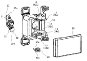
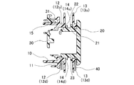
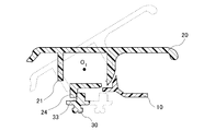
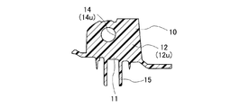
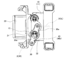
- FIG. 1 It is a perspective view of the glove box to which the glove box lock device concerning one embodiment is applied. It is an exploded perspective view of the glove box lock device of an embodiment. It is sectional drawing when the glove box lock device of the embodiment is cut along a plane including a vertical direction. It is sectional drawing when the glove box lock device of embodiment is cut
- the glove box lock device 1 is a lock device that is attached to a glove box 2 of a vehicle and that opens and closes the glove box 2.
- the grab box 2 is a storage unit installed in an interior member such as an instrument panel in front of a passenger seat in a vehicle compartment, and is opened and closed with respect to the instrument panel and the like.
- the grab box lock device 1 includes a base member 10, a knob member 20, an arm member 30, and a spring member 40, as shown in FIGS. 1, 2, 3, and 4.
- the grab box lock device 1 includes a base member 10, a knob member 20, an arm member 30, and a spring member 40.
- the base member 10 is a member attached and fixed to the glove box 2.
- the base member 10 is arranged on the back surface side of the glove box 2.
- the base member 10 has a plate wall portion 11, a horizontal portion 12, and a shaft portion 13.
- the plate wall portion 11 is formed so as to extend in parallel to the back surface side of the glove box 2.
- the horizontal portion 12 is formed so as to project horizontally from the plate wall portion 11.
- the horizontal portions 12 are provided at two locations above and below the plate wall portion 11.
- the shaft portion 13 is formed in a cylindrical shape.
- the shaft portions 13 are provided at two upper and lower locations and extend in the vertical direction from the horizontal portions 12 at the two upper and lower locations.
- the upper horizontal portion 12 and the shaft portion 13 will be referred to as the upper horizontal portion 12u and the upper shaft portion 13u
- the lower horizontal portion 12 and the shaft portion 13 will be referred to as the lower horizontal portion 12d and the lower shaft portion 13d, respectively.
- the upper shaft portion 13u extends upward from the upper surface of the upper horizontal portion 12u.
- the lower shaft portion 13d extends downward from the lower surface of the lower horizontal portion 12d.
- a through hole 14u is provided in the upper horizontal portion 12u.
- the through hole 14u vertically penetrates the upper horizontal portion 12u and communicates with the hollow portion of the upper shaft portion 13u.
- a through hole 14d is provided in the lower horizontal portion 12d.
- the through hole 14d vertically penetrates the lower horizontal portion 12d and communicates with the hollow portion of the lower shaft portion 13d.
- a space is formed in the base member 10 between the upper horizontal portion 12u and the lower horizontal portion 12d.
- the front end of the glove box 2 in the horizontal portion 12 is formed so that a knob member 20 described later in detail can rotate about a shaft portion 13. Further, the end of the horizontal portion 12 abuts on the knob member 20 when the knob member 20 reaches the closed position from the open position side, so that the rotation of the knob member 20 beyond the closed position is restricted. Is formed in.
- the knob member 20 is a plate-shaped member that can be opened by the operator.
- the knob member 20 is arranged on the surface of the glove box 2.
- the knob member 20 is an operation unit that opens the glove box 2 by inserting an operator's finger between the knob member 20 and the glove box 2 and pulling one end side (the right side in FIGS. 1 and 2) of the knob member 20 toward you. Is.
- the knob member 20 has a housing portion 21.
- the housing portion 21 is a portion housed in the space between the upper horizontal portion 12u and the lower horizontal portion 12d of the base member 10.
- the accommodating portion 21 is provided with insertion portions 22 and 23.
- the insertion portions 22 and 23 are each formed in a cylindrical shape or a cylindrical shape.
- the insertion portion 22 is provided on the upper portion of the housing portion 21 and projects upward.
- the insertion portion 23 is provided in the lower portion of the housing portion 21 and projects downward.
- the insertion portion 22 is inserted into the through hole 14u of the upper horizontal portion 12u.
- the insertion portion 23 is inserted into the through hole 14d of the lower horizontal portion 12d.
- the knob member 20 is rotatably supported by the base member 10 about the insertion portions 22 and 23, that is, the upper shaft portion 13u and the lower shaft portion 13d (that is, the rotation center O 1 ).
- the knob member 20 is rotatable between a closed position parallel to the surface of the glove box 2 and an open position for opening the glove box 2.
- the knob member 20 has an arm contact portion 24 and a spring locking portion 25, as shown in FIGS. 3, 4, 6, and 8.
- the arm contact portion 24 extends from the plate-shaped main body of the knob member 20 toward the front side of the front surface of the glove box 2 and is in contact with the arm member 30 described in detail later.
- the arm contact portion 24 has a role of transmitting the rotation of the knob member 20 to the arm member 30.
- the spring locking portion 25 is a portion to which one end 40a of the spring member 40, which will be described in detail later, is locked.
- the spring locking portion 25 is formed in a groove shape so that the one end portion 40a of the spring member 40 fits therein.
- the arm member 30 is a member that swings with respect to the base member 10, and is swingably supported by the base member 10.
- the arm member 30 is arranged on the back side of the base member 10.
- the arm member 30 has a cylindrical shaft portion 31.
- the shaft portion 31 is provided at the center of the arm in the longitudinal direction.
- the shaft portion 31 is externally inserted into the shaft portion 15 provided on the back surface of the base member 10.
- the shaft portion 15 projects from the back surface of the plate wall portion 11 of the base member 10 to the inner side in the horizontal direction in a cylindrical shape.
- the shaft portions 15 are provided at two positions, upper and lower, and extend from the plate wall portion 11 inward in the horizontal direction.
- the shaft portion 31 is externally fitted to the lower shaft portion 15 of the shaft portions 15 at two locations.
- the arm member 30 is swingably supported by the base member 10 at the center of the arm in the longitudinal direction (swing center O 2 ).
- Arm member 30 has an upper 30u extending upward from the swing center O 2, and a lower 30d extending downward from the swing center O 2, the.
- Bars 3 extending in a rod shape are connected to the upper portion 30u and the lower portion 30d of the arm member 30, respectively, as shown in FIGS.
- the barb 3 is a member for opening and closing the glove box 2.
- the bar 3 includes a left bar 3L that extends to the left of the arm member 30 and a right bar 3R that extends to the right of the arm member 30 when viewed from the side where the knob member 20 is operated.
- the left bar 3L is rotatably supported by the upper portion 30u of the arm member 30.
- the tip portion of the left side bar 3L engages with and disengages from the interior member located on the left side of the glove box 2 when viewed from the side where the knob member 20 is operated.
- the right bar 3R is rotatably supported by the lower portion 30d of the arm member 30. The tip portion of the right bar 3R engages with and disengages from the interior member located on the right side of the glove box 2 when viewed from the side where the knob member 20 is operated.
- the arm member 30 has a lock position for holding the glove box 2 in a closed lock state so that the left side bar 3L and the right side bar 3R advance and retract with respect to the interior member from the glove box 2 in synchronization with each other, and the glove box 2 It is possible to swing about the swing center O 2 between the lock release position and the lock release position for releasing the lock state.
- the arm member 30 has a portion that restricts swinging beyond the lock position by coming into contact with the base member 10 when reaching the lock position from the lock release position side.
- the restricting portion of the arm member 30 when the arm member 30 reaches the lock position from the lock release position side, the barb 3 comes into contact with the interior member side to prevent further advancement thereof. Swing exceeding the lock position is restricted.
- the arm member 30 has a spring locking portion 32 and a knob contact portion 33.
- the spring locking portion 32 is a portion to which the other end 40b of the spring member 40, which will be described in detail later, is locked, and is provided in the lower portion 30d of the arm member 30.
- the spring locking portion 32 is formed in a groove shape so that the other end portion 40b of the spring member 40 fits therein.
- the knob contact portion 33 is a portion that contacts the arm contact portion 24 of the knob member 20, and is provided on the upper portion 30u of the arm member 30.
- the knob contact portion 33 is formed to project from the surface of the arm member 30 facing the base member 10 toward the base member 10.
- the spring member 40 is a torsion coil spring that rotates the knob member 20 to the closed position around the lower shaft portion 13d of the base member 10 and generates a biasing force that swings the arm member 30 to the lock position.
- the spring member 40 is rotatably attached to the shaft portion 13 of the base member 10 (specifically, the lower shaft portion 13d).
- the spring member 40 is not fixed to the base member 10 but is supported so as to be allowed to rotate around the lower shaft portion 13d.
- the spring member 40 is configured such that one end portion 40a is engaged with the spring engagement portion 25 of the knob member 20 and the other end portion 40b is engaged with the spring engagement portion 32 of the arm member 30. ..
- the knob contact portion 33 of the arm member 30 contacts the arm contact portion 24, and the pressing force applied from the arm contact portion 24 to the knob contact portion 33 is small. It is set to be almost zero, or the knob contact portion 33 does not contact the arm contact portion 24.
- the arm member 30 is in the first rotation direction (the counterclockwise direction in FIG. 2 and the clockwise direction in FIG. 7) about the swing center O 2 by the urging force of the spring member 40. The rocking is restricted to the locked position.
- the knob member 20 is operated to open from the closed position to the open position, the operating force increases the pressing force applied from the arm contact portion 24 to the knob contact portion 33, causing the arm member 30 to rock. It swings in the second rotation direction (clockwise direction in FIG. 2 and counterclockwise direction in FIG. 9) opposite to the above-described first rotation direction around the movement center O 2 .
- the spring member 40 is maintained in a wound state in the circumferential direction rather than the natural state of the spring member 40 at the closed position of the knob member 20 by the bartack lock.
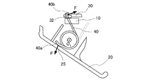
- the spring member 40 generates an urging force F that rotates the knob member 20 toward the closed position and swings the arm member 30 toward the locked position.
- the biasing force F of the spring member 40 is the smallest force F0 at the closed position of the knob member 20, and gradually increases from the closed position of the knob member 20 to the open position.
- one end 40a rotates around the shaft 13 (center O 1 ) that rotates the knob member 20 to the closed position (counterclockwise direction in FIG. 6), and the other end 40b rotates the arm member 30.
- the rotation direction (clockwise direction in FIG. 6) around the shaft portion 13 (center O 1 ) for rotating the shaft to the lock position is opposite to each other.
- the spring member 40 rotates in a rotation direction in which the one end portion 40 a side rotates around the shaft portion 13 by being locked with the knob member 20 when the knob member 20 rotates from the closed position side to the open position side (during an opening operation).
- Lockwise direction in FIG. 6) and a rotation direction (counterclockwise in FIG. 6) in which the other end portion 40b rotates around the shaft portion 13 due to the swinging of the arm member 30 due to the contact between the knob member 20 and the arm member 30. And the direction of rotation) are opposite to each other.
- the spring member 40 In the grab box lock device 1, the spring member 40 generates an urging force that rotates the knob member 20 to the closed position and swings the arm member 30 to the locked position around the lower shaft portion 13d of the base member 10. Therefore, when the knob member 20 is not opened while the glove box 2 is closed, the urging force of the spring member 40 keeps the knob member 20 in the closed position and the arm member 30. Are maintained in the locked position. In this case, the barb 3 advances from the glove box 2 to the interior member side and engages with the interior member side, so that the glove box 2 is closed.
- the arm contact portion 24 of the knob member 20 abuts the knob contact portion 33 of the arm member 30 and the arm. Since the member 30 is pressed in the second rotation direction, the arm member 30 swings in the second rotation direction against the biasing force of the spring member 40. When the arm member 30 swings to the unlocked position, the barb 3 retracts to the glove box 2 side and the engagement with the interior member side is released, so that the glove box 2 is opened.
- the arm member 30 swings in accordance with the opening operation of the knob member 20 as described above, the biasing force applied from the spring member 40 to the knob member 20 in the closing position direction by the opening operation of the knob member 20 increases. .. Therefore, it is possible to realize the load release at the time of the opening operation of the knob member 20.
- the biasing force applied from the spring member 40 to the arm member 30 in the lock position direction increases due to the swinging of the arm member 30. Therefore, after swinging the arm member 30 to the unlock position, the arm member 30 can be automatically restored from the unlock position to the lock position after the opening operation of the knob member 20 is released. .. Accordingly, after the glove box 2 is opened, the barb 3 can be advanced from the glove box 2 to the interior member side and engaged with the interior member side in the opened state.
- the barb 3 is advanced to the interior member side and the spring member 40 is attached immediately before engaging with the interior member side.
- the bar 3 By being pressed against the engaging portion on the side of the interior member against the force of force, it slightly retracts to the glove box 2 side.
- the bar 3 is retracted, the arm member 30 swings from the lock position to the unlock position side.
- the retreat amount of the barb 3 that is, the swing angle of the arm member 30 toward the unlocked position side, is set so that the knob member 20 of the spring member 40 is rotated to the closed position and the arm member 30 is swung to the locked position. It is set so that power always occurs.
- the arm member 30 is biased to the lock position by the biasing force of the spring member 40. Therefore, when the pressing force in the backward direction applied to the bar 3 from the engaging portion on the interior member side as described above disappears, the bar 3 swings to the lock position by the urging force of the spring member 40. Goes back to the interior material side again. In this case, the glove box 2 is closed by engaging the barb 3 with the interior member side. Further, in this case, since the biasing force applied from the spring member 40 to the knob member 20 in the closing position direction is continuously maintained in the process of closing the glove box 2 from the opened state, the knob member is maintained. It is possible to prevent the rotation of the knob member 20 to the open position side, and thereby to prevent the knob member 20 from rattling when the glove box 2 is moved from the open door to the closed door.
- a lock function for opening and closing the glove box 2 without rattling the knob member 20 when the glove box 2 is moved from the open door to the closed door is realized by using one spring member 40.
- the spring member 40 is rotatably mounted on the shaft portion 13 of the base member 10 (specifically, the lower shaft portion 13d) and is not fixed to the base member 10 but rotatably supported. ..
- the biasing force of the spring member 40 is such that one end portion 40a rotates around the shaft portion 13 that rotates the knob member 20 to the closed position, and the other end portion 40b rotates around the shaft portion 13 that rotates the arm member 30 to the lock position.
- the lock function of opening and closing the glove box 2 without rattling the knob member 20 when the glove box 2 is changed from the open door to the closed door is achieved by using one spring member 40. While realizing it, it is possible to reduce the assembly man-hour.
- the shaft portion 13 of the base member 10 extends in the vertical direction, and the knob member 20 swings about the shaft portion 13 in a plane including the horizontal direction.
- the present invention is not limited to this, and the shaft portion 13 of the base member 10 extends in the horizontal direction, and the knob member 20 swings about the shaft portion 13 in a plane including the vertical direction. It may be applied to things.
- the horizontal portion 12, the shaft portion 13, and the shaft portion 15 of the base member 10 are provided at two upper and lower positions, and the spring member 40 is rotatably externally inserted to the lower shaft portion 13d.
- the arm member 30 is externally attached to the lower shaft portion 15 so as to be swingable.
- the present invention is not limited to this, and the spring member 40 is rotatably externally inserted to the upper shaft portion 13u, and the arm member 30 is oscillatably externally inserted to the upper shaft portion 15. It may be applied.
- the glove box 2 is opened by a right-side opening operation in which the right side of the knob member 20 is pulled toward the base member 10 as shown in FIGS. 1 and 2.
- the present invention is not limited to this, and the glove box 2 may be applied to the one in which the left side of the knob member 20 is opened by the left side opening operation in which the left side of the knob member 20 is pulled toward the base member 10.
- the base member 10 has the horizontal portion 12, the shaft portion 13, and the shaft portion 15, which are provided at upper and lower two positions, respectively.
- a component including the base member 10 includes a configuration in which the opening operation of the glove box 2 is realized by the right opening operation of the knob member 20 and a configuration in which the opening operation of the glove box 2 is realized by the left opening operation of the knob member 20. Can be shared.
Landscapes
- Engineering & Computer Science (AREA)
- Mechanical Engineering (AREA)
- Vehicle Step Arrangements And Article Storage (AREA)
- Lock And Its Accessories (AREA)
Abstract
グラブボックスロック装置は、所望のロック機能を一つのスプリング部材で実現しつつ、組み付け工数を削減するために、グラブボックスに取り付けられ、所定方向に延びる軸部を有するベース部材と、ベース部材に軸部を中心にして閉位置と開位置との間で回動可能に支持されるノブ部材と、長手方向中心部でベース部材に揺動可能に支持され、一端部でノブ部材に当接し、グラブボックスのロック位置とロック解除位置との間で揺動するアーム部材と、軸部に回転可能に外挿され、一端部でノブ部材に係止され、他端部でアーム部材の他端部に係止され、ノブ部材を閉位置へ回動させかつアーム部材をロック位置へ揺動させる付勢力を発生するスプリング部材と、を備える。スプリング部材の一端部がノブ部材を閉位置へ回動させる軸部回りの回転方向と、スプリング部材の他端部がアーム部材をロック位置へ揺動させる軸部回りの回転方向と、は互いに逆向きである。
Description
本発明は、例えば車両に搭載されるグラブボックスロック装置に関する。
従来、例えば車両に搭載されるグラブボックスロック装置が知られている(例えば、特許文献1)。グラブボックスロック装置は、ベース部材と、ノブ部材と、ドグ部材と、スプリング部材と、を備えている。ベース部材は、グラブボックスに取り付けられている。ノブ部材は、グラブボックスの表側に配置された、操作者が開操作することが可能な部材であって、ベース部材に閉位置と開位置との間で回動可能に支持されている。ノブ部材は、ドグ部材に係止されている。ドグ部材は、ベース部材に、グラブボックス側のストライカに係合する係合位置とその係合が解除される係合解除位置との間で移動可能に取り付けられている。スプリング部材は、中央部でベース部材に支持固定されており、一端部でノブ部材に係止され、他端部でドグ部材に係止されている。
上記のグラブボックスロック装置において、スプリング部材の中央部よりも一端部側でノブ部材が閉位置へ付勢され、スプリング部材の中央部よりも他端部側でドグ部材が係合位置へ付勢されている。すなわち、一つのスプリング部材を用いてノブ部材及びドグ部材が個別に独立して閉位置や係合位置へ付勢されている。ノブ部材は、スプリング部材の一端側から付勢力が付与された状態で所定の閉位置に規制されて位置固定されている。ドグ部材は、スプリング部材の他端側から付勢力が付与された状態で所定の係合位置に規制されて位置固定されている。
上記のグラブボックスロック装置において、ノブ部材が閉位置から開操作された際、スプリング部材からそのノブ部材に付与される閉位置方向への付勢力が大きくなるので、ノブ部材の開操作時における荷重出しを実現することができる。また、スプリング部材からドグ部材に付与される係合位置方向への付勢力が大きくなるので、そのドグ部材の係合解除位置への移動後、ノブ部材の開操作解除後にそのドグ部材を係合解除位置から係合位置まで自動的に復元する動作を実現させることができる。更に、グラブボックスが開扉された状態から閉扉される際、ストライカとの当接によりドグ部材が係合位置から係合解除位置へ移動しても、直ちにスプリング部材の付勢力によりドグ部材が係合解除位置から係合位置へ戻されるので、ノブ部材が開位置側へ回動するのを防止することができ、これにより、グラブボックスの開扉から閉扉への移行時におけるノブ部材のガタツキを防止することができる。
しかしながら、上記のグラブボックスロック装置では、ノブ部材とドグ部材とを個別に閉位置や係合位置へ付勢するためにスプリング部材の中央部をベース部材に支持固定することが必要であるので、組み付け工数が増加してしまう。
本発明は、このような点に鑑みてなされたものであり、所望のロック機能を一つのスプリング部材で実現しつつ、組み付け工数を削減することが可能なグラブボックスロック装置を提供することを目的とする。
本発明の一態様は、グラブボックスに取り付けられ、所定方向に延びる軸部を有するベース部材と、前記グラブボックスの表側に配置され、前記ベース部材に前記軸部を中心にして閉位置と開位置との間で回動可能に支持されるノブ部材と、長手方向中心部で前記ベース部材に揺動可能に支持され、一端部で前記ノブ部材に当接し、前記グラブボックスをロックさせるロック位置と前記グラブボックスのロックを解除させるロック解除位置との間で揺動するアーム部材と、前記軸部に回転可能に外挿され、一端部で前記ノブ部材に係止され、他端部で前記アーム部材の他端部に係止され、前記軸部の回りに前記ノブ部材を閉位置へ回動させると共に前記アーム部材を前記ロック位置へ揺動させる付勢力を発生するスプリング部材と、を備え、前記スプリング部材は、一端部が前記ノブ部材を閉位置へ回動させる前記軸部回りの回転方向と、他端部が前記アーム部材を前記ロック位置へ揺動させる前記軸部回りの回転方向と、が互いに逆向きであるように構成されている、グラブボックスロック装置である。
この構成によれば、グラブボックスを開閉させるロック機能を一つのスプリング部材を用いて実現することができる。また、このスプリング部材は、ベース部材の軸部に回転可能に外挿されており、スプリング部材の一端部がノブ部材を閉位置へ回動させる軸部回りの回転方向と、スプリング部材の他端部がアーム部材をロック位置へ回動させる軸部回りの回転方向と、は互いに逆向きである。この構造によれば、スプリング部材の中央部をベース部材に固定具を用いて固定することは不要であるので、グラブボックスロック装置の組み付け工数を削減することができる。
以下、図面を用いて、本発明に係るグラブボックスロック装置の具体的な実施形態について説明する。
一実施形態のグラブボックスロック装置1は、車両のグラブボックス2に取り付けられ、そのグラブボックス2を開閉するためのロック装置である。グラブボックス2は、車室内の助手席前のインストルメントパネルなどの内装部材に設置される収納部であって、インストルメントパネルなどに対して開閉される。グラブボックスロック装置1は、図1、図2、図3、及び図4に示す如く、ベース部材10と、ノブ部材20と、アーム部材30と、スプリング部材40と、を備えている。グラブボックスロック装置1は、ベース部材10と、ノブ部材20と、アーム部材30と、スプリング部材40と、により構成されている。
ベース部材10は、グラブボックス2に取り付けられ固定される部材である。ベース部材10は、グラブボックス2の表面裏側に配置されている。ベース部材10は、板壁部11と、水平部12と、軸部13と、を有している。板壁部11は、グラブボックス2の表面裏側に対して平行に広がるように形成されている。水平部12は、図5に示す如く、板壁部11から水平に広がるように突出して形成されている。水平部12は、板壁部11の上下二箇所に設けられている。軸部13は、円筒状に形成されている。軸部13は、上下二箇所に設けられており、上下二箇所の水平部12から上下方向に延びている。以下、上方側の水平部12及び軸部13を上方水平部12u及び上方軸部13uと、下方側の水平部12及び軸部13を下方水平部12d及び下方軸部13dと、それぞれ称す。
上方軸部13uは、上方水平部12uの上面から上方に延びている。下方軸部13dは、下方水平部12dの下面から下方に延びている。上方水平部12uには、貫通孔14uが設けられている。貫通孔14uは、上方水平部12uを上下方向に貫通しており、上方軸部13uの中空部に連通している。下方水平部12dには、貫通孔14dが設けられている。貫通孔14dは、下方水平部12dを上下方向に貫通しており、下方軸部13dの中空部に連通している。ベース部材10には、上方水平部12uと下方水平部12dとの間に空間が形成されている。
水平部12におけるグラブボックス2の表側の端部は、後に詳述するノブ部材20が軸部13を中心にして回動できるように形成されている。また、この水平部12の端部は、ノブ部材20が開位置側から閉位置に達した際にそのノブ部材20に当接することで、ノブ部材20の閉位置を超える回動を規制するように形成されている。
ノブ部材20は、操作者が開操作することが可能な板状の部材である。ノブ部材20は、グラブボックス2の表面に配置されている。ノブ部材20は、操作者がグラブボックス2との間に手指を挿入してノブ部材20の一端側(図1や図2における右側)を手前に引っ張ることによりグラブボックス2を開動作させる操作部である。ノブ部材20は、収容部21を有している。収容部21は、ベース部材10の上方水平部12uと下方水平部12dとの間の空間に収容される部位である。
収容部21には、挿通部22,23が設けられている。挿通部22,23はそれぞれ、円筒状又は円柱状に形成されている。挿通部22は、収容部21の上部に設けられており、上方へ突出している。挿通部23は、収容部21の下部に設けられており、下方へ突出している。挿通部22は、上方水平部12uの貫通孔14uに挿通されている。挿通部23は、下方水平部12dの貫通孔14dに挿通されている。ノブ部材20は、ベース部材10に挿通部22,23すなわち上方軸部13u及び下方軸部13d(すなわち、回動中心O1)を中心にして回動可能に支持されている。ノブ部材20は、グラブボックス2の表面に対して平行な閉位置と、グラブボックス2を開くための開位置との間で回動可能である。
ノブ部材20は、図3、図4、図6、及び図8に示す如く、アーム用当接部24と、スプリング用係止部25と、を有している。アーム用当接部24は、ノブ部材20の板状本体からグラブボックス2の表面裏側に向けて延出しており、後に詳述するアーム部材30に当接している。アーム用当接部24は、ノブ部材20の回動をアーム部材30に伝達する役割を有している。スプリング用係止部25は、後に詳述するスプリング部材40の一端部40aが係止される部位である。スプリング用係止部25は、スプリング部材40の一端部40aが嵌るように溝状に形成されている。
アーム部材30は、ベース部材10に対して揺動する部材であって、ベース部材10に揺動可能に支持されている。アーム部材30は、ベース部材10の裏側に配置されている。アーム部材30は、円筒状の軸部31を有している。軸部31は、アーム長手方向中心部に設けられている。軸部31は、ベース部材10の裏面に設けられた軸部15に外挿されている。軸部15は、ベース部材10の板壁部11の裏面から水平方向奥側へ円筒状に突出している。軸部15は、上下二箇所に設けられており、板壁部11から水平方向奥側に延びている。軸部31は、二箇所の軸部15のうち下側の軸部15に外挿されている。アーム部材30は、アーム長手方向中心部でベース部材10に揺動可能に支持されている(揺動中心O2)。
アーム部材30は、揺動中心O2から上方に延びる上部30uと、揺動中心O2から下方に延びる下部30dと、を有している。アーム部材30の上部30u及び下部30dにはそれぞれ、図7及び図9に示す如く、棒状に延びる閂3が連結されている。閂3は、グラブボックス2を開閉させるための部材である。閂3は、ノブ部材20が操作される側から見て、アーム部材30に対して左側に延びる左側閂3Lと、アーム部材30に対して右側に延びる右側閂3Rと、を含む。
左側閂3Lは、アーム部材30の上部30uに回動可能に支持されている。左側閂3Lの先端部は、ノブ部材20が操作される側から見てグラブボックス2に対して左側に位置する内装部材に係脱する。右側閂3Rは、アーム部材30の下部30dに回動可能に支持されている。右側閂3Rの先端部は、ノブ部材20が操作される側から見てグラブボックス2に対して右側に位置する内装部材に係脱する。アーム部材30は、左側閂3L及び右側閂3Rが互いに同期してグラブボックス2から内装部材に対して進退するように、グラブボックス2を閉じたロック状態に保持するロック位置と、そのグラブボックス2のロック状態を解除させるロック解除位置との間で、揺動中心O2を中心にして揺動することが可能である。
尚、アーム部材30は、ロック解除位置側からロック位置に達した際にベース部材10に当接することで、ロック位置を超える揺動を規制する部位を有している。或いは、このアーム部材30の規制部位に代えて、アーム部材30は、ロック解除位置側からロック位置に達した際に閂3が内装部材側に当接してその更なる進出が妨げられることで、ロック位置を超える揺動が規制されるものである。
アーム部材30は、スプリング用係止部32と、ノブ用当接部33と、を有している。スプリング用係止部32は、後に詳述するスプリング部材40の他端部40bが係止される部位であって、アーム部材30の下部30dに設けられている。スプリング用係止部32は、スプリング部材40の他端部40bが嵌るように溝状に形成されている。ノブ用当接部33は、ノブ部材20のアーム用当接部24に当接する部位であって、アーム部材30の上部30uに設けられている。ノブ用当接部33は、アーム部材30におけるベース部材10に向いた面からそのベース部材10に向けて突出するように形成されている。
スプリング部材40は、ベース部材10の下方軸部13dの回りにノブ部材20を閉位置へ回動させると共にアーム部材30をロック位置へ揺動させる付勢力を発生する捻りコイルバネである。スプリング部材40は、ベース部材10の軸部13(具体的には、下方軸部13d)に回転可能に外挿されている。スプリング部材40は、ベース部材10に固定されておらず、下方軸部13dの回りの回転が許容されるように支持されている。スプリング部材40は、一端部40aでノブ部材20のスプリング用係止部25に係止され、他端部40bでアーム部材30のスプリング用係止部32に係止されるように構成されている。
ノブ部材20は、閉位置でアーム用当接部24にアーム部材30のノブ用当接部33が当接してそのアーム用当接部24からそのノブ用当接部33に付与する押圧力がほとんどゼロであるように或いはアーム用当接部24にノブ用当接部33が当接しないように設定されている。ノブ部材20の閉位置では、アーム部材30は、スプリング部材40の付勢力により揺動中心O2を中心にして第一回動方向(図2における反時計回り方向及び図7における時計回り方向)に揺動され、ロック位置で揺動規制される。そして、ノブ部材20が閉位置から開位置へ開操作されると、その操作力により、アーム用当接部24からノブ用当接部33に付与する押圧力が大きくなり、アーム部材30が揺動中心O2を中心にして上記の第一回動方向とは逆方向の第二回動方向(図2における時計回り方向及び図9における反時計回り方向)に揺動する。
スプリング部材40は、ノブ部材20の閉位置で閂ロックによりスプリング部材40の自然状態よりも周方向に巻かれた状態に維持されている。スプリング部材40は、ノブ部材20を閉位置に向けて回動させると共にアーム部材30をロック位置に向けて揺動させる付勢力Fを発生する。スプリング部材40の付勢力Fは、ノブ部材20の閉位置で最も小さい力F0であり、ノブ部材20の閉位置から開位置にかけて徐々に大きくなる。
スプリング部材40は、一端部40aがノブ部材20を閉位置へ回動させる軸部13回り(中心O1)の回転方向(図6における反時計回り方向)と、他端部40bがアーム部材30をロック位置へ回動させる軸部13回り(中心O1)の回転方向(図6における時計回り方向)と、が互いに逆向きであるように構成されている。また、スプリング部材40は、ノブ部材20の閉位置側から開位置側への回動時(開操作時)、ノブ部材20との係止により一端部40a側が軸部13回りで回転する回転方向(図6における時計回り方向)と、ノブ部材20とアーム部材30との当接に伴うアーム部材30の揺動により他端部40b側が軸部13回りで回転する回転方向(図6における反時計回り方向)と、が互いに逆向きであるように構成されている。
次に、グラブボックスロック装置1の動作について説明する。
グラブボックスロック装置1において、スプリング部材40は、ベース部材10の下方軸部13dの回りにノブ部材20を閉位置へ回動させると共にアーム部材30をロック位置へ揺動させる付勢力を発生する。このため、グラブボックス2が閉じられている状態でノブ部材20が開操作されていないときは、そのスプリング部材40の付勢力により、そのノブ部材20が閉位置に維持されると共に、アーム部材30がロック位置に維持される。この場合には、閂3がグラブボックス2から内装部材側へ進出して内装部材側と係合することで、グラブボックス2が閉扉されている。
グラブボックスロック装置1において、スプリング部材40は、ベース部材10の下方軸部13dの回りにノブ部材20を閉位置へ回動させると共にアーム部材30をロック位置へ揺動させる付勢力を発生する。このため、グラブボックス2が閉じられている状態でノブ部材20が開操作されていないときは、そのスプリング部材40の付勢力により、そのノブ部材20が閉位置に維持されると共に、アーム部材30がロック位置に維持される。この場合には、閂3がグラブボックス2から内装部材側へ進出して内装部材側と係合することで、グラブボックス2が閉扉されている。
そして、グラブボックス2の閉状態でノブ部材20が閉位置から開操作されると、そのノブ部材20のアーム用当接部24がアーム部材30のノブ用当接部33に当接してそのアーム部材30を上記の第二回動方向へ押圧するので、そのアーム部材30がスプリング部材40の付勢力に抗して上記の第二回動方向へ揺動する。そして、アーム部材30がロック解除位置まで揺動すると、閂3がグラブボックス2側に後退して内装部材側との係合が解除されることで、グラブボックス2が開扉される。
また、上記の如くノブ部材20の開操作に伴ってアーム部材30が揺動すると、ノブ部材20の開操作によってスプリング部材40からノブ部材20に付与される閉位置方向への付勢力が大きくなる。このため、ノブ部材20の開操作時における荷重出しを実現することができる。また、ノブ部材20の開操作に伴ってアーム部材30が揺動すると、アーム部材30の揺動によってスプリング部材40からアーム部材30に付与されるロック位置方向への付勢力が大きくなる。このため、アーム部材30のロック解除位置への揺動後、ノブ部材20の開操作が解除された後にアーム部材30がロック解除位置からロック位置まで自動的に復元する動作を実現させることができる。これにより、グラブボックス2が開扉された後、その開扉状態で閂3をグラブボックス2から内装部材側へ進出させて内装部材側と係合可能とすることができる。
また、グラブボックス2が開扉状態から操作者の押圧操作により閉扉される際には、閂3が、内装部材側へ進出した状態でその内装部材側との係合直前にスプリング部材40の付勢力に抗してその内装部材側の係合部位に押圧されることでグラブボックス2側へ僅かに後退する。閂3が後退すると、アーム部材30がロック位置からロック解除位置側へ揺動する。この際における閂3の後退量すなわちアーム部材30のロック解除位置側への揺動角度は、スプリング部材40においてノブ部材20を閉位置へ回動させると共にアーム部材30をロック位置へ揺動させる付勢力が常に発生するように設定されている。
アーム部材30は、スプリング部材40の付勢力によりロック位置へ付勢されている。このため、上記の如く内装部材側の係合部位から閂3に付与された後退方向側の押圧力が無くなると、スプリング部材40の付勢力によるアーム部材30のロック位置への揺動により閂3が再び内装部材側へ進出する。この場合には、閂3が内装部材側と係合することで、グラブボックス2が閉扉される。また、この場合には、グラブボックス2が開扉状態から閉扉される過程で、スプリング部材40からノブ部材20に付与される閉位置方向への付勢力が継続して維持されるので、ノブ部材20が開位置側へ回動するのを防止することができ、これにより、グラブボックス2の開扉から閉扉への移行時におけるノブ部材20のガタツキを防止することができる。
また、グラブボックスロック装置1においては、グラブボックス2の開扉から閉扉への移行時にノブ部材20をガタつかせることなくグラブボックス2を開閉させるロック機能を、一つのスプリング部材40を用いて実現することができる。このスプリング部材40は、ベース部材10の軸部13(具体的には、下方軸部13d)に回転可能に外挿されており、ベース部材10に固定されておらず回転可能に支持されている。
スプリング部材40の付勢力は、一端部40aがノブ部材20を閉位置へ回動させる軸部13回りの回転方向と、他端部40bがアーム部材30をロック位置へ回動させる軸部13回りの回転方向と、が互いに逆向きであるように作用する。この構造によれば、スプリング部材40をベース部材10に対して自己的に固定することができ、スプリング部材40の中央部をベース部材10に固定具を用いて固定することは不要である。このため、グラブボックスロック装置1の組み立て時においてスプリング部材40を取り扱い易くすることができ、スプリング部材40を組み付けし易くすることができ、これにより、グラブボックスロック装置1の組み付け工数を削減することができ、製造コストを削減することが可能である。
従って、グラブボックスロック装置1によれば、グラブボックス2の開扉から閉扉への移行時にノブ部材20をガタつかせることなくグラブボックス2を開閉させるロック機能を、一つのスプリング部材40を用いて実現しつつ、その組付け工数を削減することができる。
ところで、上記の実施形態においては、ベース部材10の軸部13が上下方向に延び、ノブ部材20がその軸部13を中心にして水平方向を含む面内で揺動する。しかしながら、本発明は、これに限定されるものではなく、ベース部材10の軸部13が水平方向に延び、ノブ部材20がその軸部13を中心にして鉛直方向を含む面内で揺動するものに適用することとしてもよい。
また、上記の実施形態においては、ベース部材10の水平部12、軸部13、及び軸部15が上下二箇所に設けられていると共に、スプリング部材40が下方軸部13dに回転可能に外挿され、アーム部材30が下側の軸部15に揺動可能に外挿されている。しかしながら、本発明は、これに限定されるものではなく、スプリング部材40が上方軸部13uに回転可能に外挿され、アーム部材30が上側の軸部15に揺動可能に外挿されるものに適用することとしてもよい。
また、上記の実施形態においては、グラブボックス2が、図1及び図2に示す如くノブ部材20の右側がベース部材10に対して手前に引かれる右側開操作により開動作することとしている。しかし、本発明は、これに限定されるものではなく、グラブボックス2が、ノブ部材20の左側がベース部材10に対して手前に引かれる左側開操作により開動作するものに適用することとしてもよい。尚、上記の実施形態においては、ベース部材10が、それぞれ上下二箇所に設けられた、水平部12、軸部13、及び軸部15を有している。このため、グラブボックス2の開動作をノブ部材20の右側開操作で実現する構成と、グラブボックス2の開動作をノブ部材20の左側開操作で実現する構成と、でベース部材10を含む部品の共通化を図ることができる。
尚、本発明は、上述した実施形態や変形形態に限定されるものではなく、本発明の趣旨を逸脱しない範囲で種々の変更を施すことが可能である。
1:グラブボックスロック装置、2:グラブボックス、3:閂、10:ベース部材、13:軸部、20:ノブ部材、24:アーム用当接部、25:スプリング用係止部、30:アーム部材、32:スプリング用係止部、33:ノブ用当接部、40:スプリング部材。
Claims (4)
- グラブボックスに取り付けられ、所定方向に延びる軸部を有するベース部材と、
前記グラブボックスの表側に配置され、前記ベース部材に前記軸部を中心にして閉位置と開位置との間で回動可能に支持されるノブ部材と、
長手方向中心部で前記ベース部材に揺動可能に支持され、一端部で前記ノブ部材に当接し、前記グラブボックスをロックさせるロック位置と前記グラブボックスのロックを解除させるロック解除位置との間で揺動するアーム部材と、
前記軸部に回転可能に外挿され、一端部で前記ノブ部材に係止され、他端部で前記アーム部材の他端部に係止され、前記軸部の回りに前記ノブ部材を閉位置へ回動させると共に前記アーム部材を前記ロック位置へ揺動させる付勢力を発生するスプリング部材と、
を備え、
前記スプリング部材は、一端部が前記ノブ部材を閉位置へ回動させる前記軸部回りの回転方向と、他端部が前記アーム部材を前記ロック位置へ揺動させる前記軸部回りの回転方向と、が互いに逆向きであるように構成されている、グラブボックスロック装置。 - 前記スプリング部材は、前記ノブ部材の閉位置側から開位置側への回動時、前記ノブ部材との係止により前記スプリング部材の一端部側が前記軸部回りで回転する回転方向と、前記ノブ部材と前記アーム部材との当接に伴う前記アーム部材の揺動により前記スプリング部材の他端部側が前記軸部回りで回転する回転方向と、が互いに逆向きであるように構成されている、請求項1に記載されたグラブボックスロック装置。
- 前記スプリング部材による前記付勢力は、前記ノブ部材の閉位置側から開位置側にかけて大きくなる、請求項1又は2に記載されたグラブボックスロック装置。
- 前記ノブ部材は、前記アーム部材に向けて延出された、前記アーム部材の一端部に当接するアーム用当接部を有する、請求項1乃至3の何れか一項に記載されたグラブボックスロック装置。
Priority Applications (1)
| Application Number | Priority Date | Filing Date | Title |
|---|---|---|---|
| US17/290,286 US11708710B2 (en) | 2018-11-30 | 2019-09-12 | Glove compartment lock device |
Applications Claiming Priority (2)
| Application Number | Priority Date | Filing Date | Title |
|---|---|---|---|
| JP2018225764A JP6950668B2 (ja) | 2018-11-30 | 2018-11-30 | グラブボックスロック装置 |
| JP2018-225764 | 2018-11-30 |
Publications (1)
| Publication Number | Publication Date |
|---|---|
| WO2020110423A1 true WO2020110423A1 (ja) | 2020-06-04 |
Family
ID=70852791
Family Applications (1)
| Application Number | Title | Priority Date | Filing Date |
|---|---|---|---|
| PCT/JP2019/035823 Ceased WO2020110423A1 (ja) | 2018-11-30 | 2019-09-12 | グラブボックスロック装置 |
Country Status (3)
| Country | Link |
|---|---|
| US (1) | US11708710B2 (ja) |
| JP (1) | JP6950668B2 (ja) |
| WO (1) | WO2020110423A1 (ja) |
Cited By (1)
| Publication number | Priority date | Publication date | Assignee | Title |
|---|---|---|---|---|
| US20210301566A1 (en) * | 2020-03-30 | 2021-09-30 | Toyoda Gosei Co., Ltd. | Lid lock unit attachment structure |
Families Citing this family (1)
| Publication number | Priority date | Publication date | Assignee | Title |
|---|---|---|---|---|
| JP7415988B2 (ja) * | 2021-03-15 | 2024-01-17 | 豊田合成株式会社 | リッドロック装置 |
Citations (7)
| Publication number | Priority date | Publication date | Assignee | Title |
|---|---|---|---|---|
| JPH0542553U (ja) * | 1991-11-11 | 1993-06-08 | 株式会社ユーシン | グロ−ブボツクス等のリツドロツク装置 |
| JPH08207668A (ja) * | 1995-01-31 | 1996-08-13 | Alpha Corp | グローブボックスロック装置 |
| JPH1037557A (ja) * | 1996-07-30 | 1998-02-10 | Alpha Corp | リッドのロック装置 |
| JP2013023995A (ja) * | 2011-07-25 | 2013-02-04 | Inoac Corp | ロック装置 |
| CN203729723U (zh) * | 2014-02-14 | 2014-07-23 | 上海琦天汽车科技有限公司 | 双侧锁定装置 |
| WO2015163282A1 (ja) * | 2014-04-24 | 2015-10-29 | 株式会社パイオラックス | 開閉部材のロック装置 |
| CN105370115A (zh) * | 2015-12-01 | 2016-03-02 | 重庆长安汽车股份有限公司 | 一种按扭式手套箱锁结构 |
Family Cites Families (9)
| Publication number | Priority date | Publication date | Assignee | Title |
|---|---|---|---|---|
| US3374021A (en) * | 1966-11-23 | 1968-03-19 | Gen Motors Corp | Latch operating assembly |
| KR860003652Y1 (ko) * | 1984-10-31 | 1986-12-20 | 대우중공업주식회사 | 철제 도어의 록킹 장치 |
| JPH061997Y2 (ja) * | 1987-12-24 | 1994-01-19 | アイシン精機株式会社 | 自動車用アウトサイドハンドル装置 |
| US5292159A (en) * | 1993-03-24 | 1994-03-08 | Nyx, Inc. | Latch mechanism for vehicle glove boxes or the like |
| KR100464248B1 (ko) * | 2002-02-27 | 2005-01-03 | 비스티온 인테리어스 코리아 주식회사 | 자동차 글로브 박스의 록킹장치 |
| KR100553090B1 (ko) * | 2003-11-04 | 2006-02-20 | 현대자동차주식회사 | 자동차의 글로브 박스용 로크 부설 노브 |
| US9739074B1 (en) * | 2016-02-02 | 2017-08-22 | Trimark Corporation | Twist latch for compartment door |
| CN108868393B (zh) * | 2018-08-01 | 2024-08-13 | 东莞禾盈通用零部件有限公司 | 一种拨杆式手套箱锁扣 |
| JP6579288B1 (ja) * | 2019-06-28 | 2019-09-25 | 豊田合成株式会社 | ロック機構 |
-
2018
- 2018-11-30 JP JP2018225764A patent/JP6950668B2/ja active Active
-
2019
- 2019-09-12 US US17/290,286 patent/US11708710B2/en active Active
- 2019-09-12 WO PCT/JP2019/035823 patent/WO2020110423A1/ja not_active Ceased
Patent Citations (7)
| Publication number | Priority date | Publication date | Assignee | Title |
|---|---|---|---|---|
| JPH0542553U (ja) * | 1991-11-11 | 1993-06-08 | 株式会社ユーシン | グロ−ブボツクス等のリツドロツク装置 |
| JPH08207668A (ja) * | 1995-01-31 | 1996-08-13 | Alpha Corp | グローブボックスロック装置 |
| JPH1037557A (ja) * | 1996-07-30 | 1998-02-10 | Alpha Corp | リッドのロック装置 |
| JP2013023995A (ja) * | 2011-07-25 | 2013-02-04 | Inoac Corp | ロック装置 |
| CN203729723U (zh) * | 2014-02-14 | 2014-07-23 | 上海琦天汽车科技有限公司 | 双侧锁定装置 |
| WO2015163282A1 (ja) * | 2014-04-24 | 2015-10-29 | 株式会社パイオラックス | 開閉部材のロック装置 |
| CN105370115A (zh) * | 2015-12-01 | 2016-03-02 | 重庆长安汽车股份有限公司 | 一种按扭式手套箱锁结构 |
Cited By (1)
| Publication number | Priority date | Publication date | Assignee | Title |
|---|---|---|---|---|
| US20210301566A1 (en) * | 2020-03-30 | 2021-09-30 | Toyoda Gosei Co., Ltd. | Lid lock unit attachment structure |
Also Published As
| Publication number | Publication date |
|---|---|
| JP2020084732A (ja) | 2020-06-04 |
| US11708710B2 (en) | 2023-07-25 |
| JP6950668B2 (ja) | 2021-10-13 |
| US20210381286A1 (en) | 2021-12-09 |
Similar Documents
| Publication | Publication Date | Title |
|---|---|---|
| JP3758929B2 (ja) | 自動車用ドアロック装置 | |
| JP4905716B2 (ja) | 自動車用ドアラッチ装置 | |
| US8684425B2 (en) | Vehicle door latch apparatus | |
| CA2956391C (en) | Multi-point exit device | |
| US20100127511A1 (en) | Vehicle door latch having a power lock-unlock mechanism | |
| JP4659602B2 (ja) | 車両用ドアラッチの操作装置 | |
| WO2020110423A1 (ja) | グラブボックスロック装置 | |
| JP6267944B2 (ja) | 車両用のドアラッチ装置 | |
| JP2015140614A (ja) | 車両用のドアラッチ装置 | |
| US12428883B2 (en) | Door latch device | |
| WO2020115939A1 (ja) | 自動車用ドアラッチ装置 | |
| JP2004211383A (ja) | 開閉ロック装置 | |
| JP4382121B2 (ja) | 自動車用ドアラッチ装置 | |
| JP4345432B2 (ja) | 車両用ドアラッチ機構 | |
| CN211524445U (zh) | 车用门锁装置 | |
| JP2005188242A (ja) | ロック装置 | |
| JP4423013B2 (ja) | 遊技機用施錠装置 | |
| US20250154800A1 (en) | Door latch device | |
| JP2021161635A (ja) | リッドロックユニットの取付構造 | |
| WO2010053076A1 (ja) | ドアハンドル装置 | |
| JP7653382B2 (ja) | 車載用ルーフボックスロック機構 | |
| JP2021123902A (ja) | 車両用ドアロック装置 | |
| JP3985935B2 (ja) | アクチュエータ、及びこれを備えるロック装置 | |
| JP4188739B2 (ja) | 車両用ドアラッチアクチュエータ | |
| JP2025008598A (ja) | ハンドル装置及びドア装置 |
Legal Events
| Date | Code | Title | Description |
|---|---|---|---|
| 121 | Ep: the epo has been informed by wipo that ep was designated in this application |
Ref document number: 19889672 Country of ref document: EP Kind code of ref document: A1 |
|
| NENP | Non-entry into the national phase |
Ref country code: DE |
|
| 122 | Ep: pct application non-entry in european phase |
Ref document number: 19889672 Country of ref document: EP Kind code of ref document: A1 |