WO2020105611A1 - ディスクブレーキ、摩擦パッドおよびシム - Google Patents
ディスクブレーキ、摩擦パッドおよびシムInfo
- Publication number
- WO2020105611A1 WO2020105611A1 PCT/JP2019/045198 JP2019045198W WO2020105611A1 WO 2020105611 A1 WO2020105611 A1 WO 2020105611A1 JP 2019045198 W JP2019045198 W JP 2019045198W WO 2020105611 A1 WO2020105611 A1 WO 2020105611A1
- Authority
- WO
- WIPO (PCT)
- Prior art keywords
- shim
- claw
- claw portion
- plate
- disc
- Prior art date
- Legal status (The legal status is an assumption and is not a legal conclusion. Google has not performed a legal analysis and makes no representation as to the accuracy of the status listed.)
- Ceased
Links
Images



Classifications
-
- F—MECHANICAL ENGINEERING; LIGHTING; HEATING; WEAPONS; BLASTING
- F16—ENGINEERING ELEMENTS AND UNITS; GENERAL MEASURES FOR PRODUCING AND MAINTAINING EFFECTIVE FUNCTIONING OF MACHINES OR INSTALLATIONS; THERMAL INSULATION IN GENERAL
- F16D—COUPLINGS FOR TRANSMITTING ROTATION; CLUTCHES; BRAKES
- F16D65/00—Parts or details
- F16D65/02—Braking members; Mounting thereof
- F16D65/04—Bands, shoes or pads; Pivots or supporting members therefor
- F16D65/092—Bands, shoes or pads; Pivots or supporting members therefor for axially-engaging brakes, e.g. disc brakes
- F16D65/095—Pivots or supporting members therefor
Definitions
- the present invention relates to a disc brake, a friction pad, and a shim that are preferably used to apply a braking force to a vehicle, for example.
- a disc brake is used in a vehicle such as an automobile, and is configured to apply a braking force to the vehicle by pressing a friction pad against a disc that rotates together with a wheel (for example, see Patent Documents 1 and 2).
- a pair of friction pads are provided on both sides (inner side and outer side) of the disc, and the back surface of each friction pad is formed of a thin metal plate or the like so that two discs are stacked (laminated state).
- An inner shim and an outer shim are provided for placement.
- the inner shim and the outer shim are provided with a claw portion for preventing positional displacement in order to prevent the two shims from moving relative to each other.
- the claw portion for preventing the position shift may be damaged while the outer shim repeats the relative movement with respect to the inner shim, and the relative movement of the both is not always sufficiently suppressed. There is a problem that you can not.
- An object of the present invention is to provide a disc brake, a friction pad, and a shim, which prevent the displacement of the shim and improve the braking performance.
- a disc brake includes a support member arranged to straddle an outer peripheral side of the disc in an axial direction, a pair of friction pads supported by the support member and opposed to both sides of the disc, A pair of friction pads that press against the disc, the friction pad includes a plate having a lining attached to the disc and a shim, and the shim is one of the two surfaces of the plate.
- a first shim provided on a back surface opposite to the lining, and a second shim provided on a back surface opposite to the plate on both surfaces of the first shim, overlapping the first shim.
- a first claw portion formed to extend outward in the radial direction of the disc from one of the first shim and the second shim, and near the center of the first claw portion.
- a second claw portion that is formed so as to extend outward in the disc radial direction from the formed cutout portion and the other shim of the first shim and the second shim, and that is arranged inside the cutout portion.
- the first claw part and the second claw part are bent toward the plate side, and the first claw part and the second claw part are the first claw part and the second claw part.
- Side surfaces of the claw portion and the second claw portion in a direction orthogonal to the plate thickness direction partially face each other.
- the friction pad according to the embodiment of the present invention includes a plate having a lining attached to contact with the disc and a shim, and the shim is provided on a back surface of the plate opposite to the lining.
- a first claw formed to extend outward in the disc radial direction from one of the second shim, a cutout formed near the center of the first claw, and the first claw
- the first shim and the second shim, the second claw is formed to extend outward in the disc radial direction from the other shim, and the second claw is disposed inside the cutout portion.
- the claw part and the second claw part are bent toward the plate side, and the first claw part and the second claw part are the first claw part and the second claw part.
- the side surface portions in the direction orthogonal to the plate thickness direction of the are partially opposed to each other.
- the shim according to the embodiment of the present invention includes a first shim provided on a back surface of the friction pad plate opposite to the lining, and a shim opposite the plate on both surfaces of the first shim.
- a second shim provided to overlap with the first shim and one of the first shim and the second shim on the back surface of the side extending outward in the disk radial direction.
- a first claw portion formed, a cutout portion formed in the vicinity of the center of the first claw portion, and the other shim of the first shim and the second shim outward from the disk radial direction.
- a second claw portion that is formed to extend to the inside of the cutout portion, and the first claw portion and the second claw portion are bent toward the plate side, In the first claw portion and the second claw portion, side surface portions of the first claw portion and the second claw portion in a direction orthogonal to the plate thickness direction are partially opposed to each other. There is.
- the second shim it is possible to prevent the second shim from being displaced with respect to the first shim, suppress the generation of noise such as brake squeal, and improve the braking performance. it can.
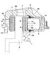
- FIG. 3 is a plan view of the disc brake according to the first embodiment as seen from above.
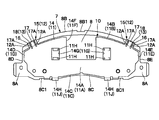
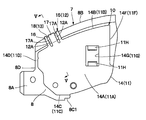
- FIG. 2 is a sectional view of the disc brake as seen from the direction of arrows II-II in FIG. 1. It is a front view which expands and shows a friction pad with a shim. It is the elements on larger scale which expanded the left side part of the friction pad shown in FIG.
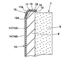
- FIG. 5 is an enlarged cross-sectional view of the plate, the lining, and the first and second shims of the friction pad as seen from the direction of the arrow VV in FIG. 4.
- FIG. 6 is a cross-sectional view showing a state before the second shim in FIG. 5 is overlapped with the first shim.
- FIGS. 1 to 8 show a first embodiment.
- a support member 1 is a mounting member (carrier) for the disc brake, which is mounted on a non-rotating portion (not shown) of the vehicle.
- the support member 1 is arranged, for example, over the inner side and the outer side of the disk 2 that rotates with the wheels.
- the disk 2 rotates, for example, in the direction of arrow A in FIG. 1 when the vehicle moves forward.
- the right side in FIG. 1 is the rotation direction inlet side (hereinafter referred to as the feed side) of the disc 2
- the left side is the rotation direction outlet side (hereinafter referred to as the feed side).
- the support member 1 includes a pair of arm portions 1A that are spaced apart in the circumferential direction of the disc 2 and extend in the axial direction so as to straddle the outer peripheral side thereof, and a support that extends in the circumferential direction of the disc so as to connect these arm portions 1A to each other.
- the portion 1B (see FIG. 2) and the reinforcing beam 1C are integrally formed.
- the support portion 1B of the support member 1 is formed thick so as to integrally connect the base end sides of the respective arm portions 1A, and is fixed to a non-rotating portion of the vehicle at a position on the inner side of the disc 2.
- the reinforcing beam 1C is formed so as to extend in the circumferential direction of the disc 2 so as to connect the tip ends of the arm portions 1A to each other on the outer side of the disc 2.
- Each arm 1A of the support member 1 is provided with a pad guide portion (not shown) which is located on the inner side and the outer side of the disc 2 and is concavely recessed. These pad guide portions cooperate with a pad spring 19 described later to guide the pair of friction pads 7 in the axial direction of the disc 2.
- each arm portion 1A of the support member 1 has the pad guide portion in order to support the pair of friction pads 7 that are arranged opposite to each other on the both sides of the disc 2 so as to be slidable in the disc axial direction.
- the caliper 3 constitutes a pressing mechanism that presses the pair of friction pads 7 against the disc 2, together with a cylinder hole 5 and a piston 6 described later.
- the caliper 3 is slidably supported by each arm 1A of the support member 1 and is arranged so as to straddle the outer periphery of the disk 2.
- the caliper 3 includes an inner leg portion 3A, a bridge portion 3B, an outer leg portion 3C, and a pair of mounting portions 3D.
- the inner leg 3A of the caliper 3 is arranged on the inner side of the disc 2, and the inner leg 3A is provided with a cylinder hole 5 and a piston 6 described later.
- the bridge portion 3B of the caliper 3 extends from the inner leg portion 3A to the outer side so as to straddle the outer peripheral side of the disc 2.
- the outer leg portion 3C extends inward in the disc radial direction from the tip end side of the bridge portion 3B and is arranged on the outer side of the disc 2, and the tip end side is formed as a bifurcated claw portion.
- the pair of mounting portions 3D are formed so as to extend in opposite directions from the inner leg portions 3A of the caliper 3 to both sides in the disc circumferential direction (rotational direction).
- Sliding pins 4 are fixedly provided on these mounting portions 3D.
- the tip ends of these sliding pins 4 extend in the disc axial direction toward the inside of each arm portion 1A (pin hole) of the support member 1.
- the tip side of each sliding pin 4 is slidably inserted into each arm 1A (pin hole) of the support member 1.
- the caliper 3 is slidably supported by the arm portions 1A of the support member 1 via the sliding pins 4 in the disc axial direction.
- each attachment portion 3D is attached to each arm portion 1A of the support member 1 by using the sliding pin 4 (see FIG. 1). This allows the caliper 3 to be slidably displaced in the axial direction of the disc 2.
- each piston 6 is slidably fitted in each cylinder hole 5 of the caliper 3.
- each piston 6 is formed in a bottomed cylindrical shape, and its protruding end side is an annular contact portion 6A that contacts (contacts) a shim 14 described later.
- the annular contact portion 6A of the piston 6 has a size that fits (does not protrude) into the outer edge (peripheral edge) of the inner friction pad 7 (plate 8) described later.
- Each piston 6 presses the inner friction pad 7 against the disc 2 when the brake fluid pressure is supplied into each cylinder hole 5.
- each piston 6 moves in the disc axial direction, and the annular contact portion 6A of each piston 6 causes friction on the inner side.
- the pad 7 is pressed against the disc 2.
- the caliper 3 is displaced in the disc axial direction toward the inner side by the reaction force from each piston 6.
- the outer leg portion 3C presses the outer friction pad 7 against the disc 2.
- the friction pads 7 are pressed against both surfaces of the disc 2 to apply a braking force to the vehicle.
- the pair of friction pads 7 are supported by the respective arm portions 1A of the support member 1 via the pad guide portions, and are arranged on both sides (that is, the inner side and the outer side) of the disc 2 so as to face each other.
- the inner friction pad 7 is arranged between the piston 6 and the disc 2 of the caliper 3 (inner leg 3A side), and the outer friction pad 7 of the caliper 3 is arranged as shown in FIG. It is arranged between the outer leg portion 3C and the disc 2.
- Each of the friction pads 7 is, for example, a plate 8 as a back plate called a back metal, a lining 9 which is provided by being bonded (fixed) to the front surface side of the plate 8, and which is in frictional contact with the disc 2 and both surfaces of the plate 8.
- the lining 9 and the laminated shim 10 arranged on the back surface opposite to the lining 9 are included.
- the laminating shim 10 is laminated on the first shim 11 provided on the back surface of the plate 8 opposite to the lining 9 and on the back surface of the first shim 11 opposite to the plate 8.
- the second shim 14 is provided so as to be overlapped with each other.
- the plate 8 is formed of a substantially fan-shaped metal plate (plate body) extending in the circumferential direction (rotational direction) of the disk 2, and has substantially square protrusions 8A on both end sides thereof. , 8A are integrally provided.
- each protrusion 8A is slidably fitted to each arm 1A (pad guide portion) of the support member 1 via a pad spring 19 described below, and these arm portions 1A (pad guide Are supported by the support member 1 so as to be displaceable in the axial direction of the disc 2 between the parts.
- the plate 8 includes an outer peripheral edge portion 8B located on the outer side in the disc radial direction, an inner peripheral edge portion 8C located on the inner side in the disc radial direction, and a disc between the outer and inner peripheral edge portions 8B, 8C. It is configured to include a side edge portion 8D on one side (for example, a feed-in side) and a side edge portion 8E on the other side (for example, a feed-out side) located on both sides in the circumferential direction.
- Each protrusion 8A of the plate 8 is formed as an ear protruding from the side edge portions 8D and 8E on one side and the other side toward both sides in the disc circumferential direction.
- the outer peripheral edge portion 8B of the plate 8 is formed as an edge portion that has a left-right symmetrical arc shape (for example, an arc shape corresponding to the outer diameter of the disk 2) with respect to the concave portion 8B1 located in the middle portion in the circumferential direction. ing. Further, a pair of left and right mounting recesses 8C1 are formed on the inner peripheral edge 8C of the plate 8 at a position spaced apart from each protrusion 8A by a predetermined dimension, and these mounting recesses 8C1 are provided with shims 11 and 14 to be described later. The bent portions 11J and 14H are locked.
- the first shim 11 is an inner fixed shim that is attached to the plate 8 of the friction pad 7 in a contact (surface contact) state.
- the first shim 11 is formed, for example, by pressing a metal plate (stainless steel plate) having a spring property, and the surface thereof has a coating film (not shown) made of a material such as hard rubber or synthetic resin. Is coated. Note that this coating is not necessarily provided, and in some cases, a metal plate such as a steel plate may be used as it is as the first shim 11.
- the first shim 11 includes an abutting plate portion 11A formed as a substantially fan-shaped flat plate extending in the circumferential direction of the disk 2 and a corresponding abutting plate portion 11A.
- Outer peripheral edge portion 11B located on the outer side in the disk radial direction
- inner peripheral edge portion 11C located on the inner side in the disk radial direction, and on both sides in the disk circumferential direction between these outer and inner peripheral edge portions 11B, 11C. It is configured to include a side edge portion 11D on one side (for example, a feeding side) and a side edge portion 11E on the other side (for example, a feeding side).
- the first shim 11 includes a U-shaped central notch portion 11F which is located at an intermediate portion in the left and right directions of the contact plate portion 11A, and which opens to an outer peripheral edge portion 11B in the disc radial direction, and the central notch portion.
- the first shim 11 is integrally formed with a pair of first claw portions 12 on an outer peripheral edge portion 11B in the disc radial direction.
- the pair of first claw portions 12 are arranged in positions symmetrical with respect to the left and the right, separated from the central cutout portion 11F in the disk circumferential direction.
- the pair of first claw portions 12 is also separated from the left and right side edge portions 11D and 11E in the disc circumferential direction, and the circumferential position thereof is the left and right side edge portions. The position is relatively close to 11D and 11E, and is relatively far from the central cutout 11F.
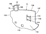
- the first claw portion 12 constitutes a first claw portion which is formed to extend outward from the first shim 11 in the disc radial direction, and is a substantially quadrangular frame-shaped body as shown in FIG. 7. .. Therefore, a rectangular cutout 13 is formed as a punched hole near the center (that is, inside) of the first claw portion 12.
- the side surface portion (that is, the inner side surface portion 12A) of the first pawl portion 12 in the direction orthogonal to the plate thickness direction of the pawl portion is a peripheral wall surface that surrounds the cutout portion 13 from the outside.
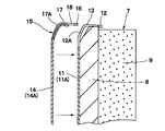
- the inner side surface portion 12A partially opposes an outer side surface portion 17A of an inner claw 17 described later in the disc circumferential direction when the first shim 11 and the second shim 14 are overlapped with each other as shown in FIG. 5, for example. Placed in position.
- the first claw portion 12 is bent toward the outer peripheral edge portion 8B of the plate 8, whereby the first shim 11 is aligned with the outer peripheral edge portion 8B of the plate 8. It is prevented from coming off via the first claw portion 12. That is, when the first shim 11 is press-molded, the first claw portion 12 is formed by bending it toward the outer peripheral edge portion 8B of the plate 8 as shown in FIGS.
- the first claw portion 12 is engaged with the outer peripheral edge portion 8B of the plate 8 in an elastically deformed state.
- the bent portions 11J of the first shim 11 are engaged with the left and right mounting recesses 8C1 formed in the inner peripheral edge portion 8C of the plate 8, respectively.
- the first shim 11 is fixed to the plate 8 in a retaining state while being overlapped with the back surface of the plate 8.
- the second shim 14 is an outer shim provided on the back surface of the first shim 11 opposite to the plate 8 on both sides thereof.
- the second shim 14 is formed by pressing a metal plate (stainless steel plate) having a spring property, for example, and the surface thereof is made of, for example, hard rubber or synthetic resin.
- a coating of material (not shown) is coated. Note that this coating is not necessarily provided, and in some cases, a metal plate such as a steel plate may be used as it is as the second shim 14.
- the second shim 14 is similar to the above-described first shim 11 in that the contact plate portion 14A, the outer peripheral edge portion 14B, the inner peripheral edge portion 14C, the one side edge portion 14D, and the other side edge portion. 14E and a U-shaped central notch 14F. Further, the contact plate portion 14A of the second shim 14 is provided with a substantially quadrangular opening portion 14G at a position separated from the central cutout portion 14F in the left and right directions. When the second shim 14 is superposed on the first shim 11, the bent pieces 11H of the first shim 11 are inserted into the opening 14G as shown in FIGS. 3 and 4. ..
- each bent piece portion 11H of the first shim 11 is formed by bending a part of the notch (opening portion 11G) formed in the first shim 11 in the disc axial direction. Then, each bent piece portion 11H of the first shim 11 is inserted into the inner rule of the hole (that is, the opening portion 14G) formed in the second shim 14. As a result, in the second shim 14, the peripheral wall side of the opening 14G is engaged with each bent piece portion 11H, and the relative movement of the second shim 14 with respect to the first shim 11 is suppressed.
- left and right bent portions 14H are formed on an inner peripheral edge portion 14C on the inner side in the disk radial direction.
- the bent portions 14H are formed in the same manner as the bent portions 11J of the first shim 11, and the mounting recesses 8C1 of the plate 8 are engaged with the bent portions 11J and 14H.
- each bent portion 14H of the second shim 14 is attached to the bent portion 11J from above so as to overlap with each other so as to cover each bent portion 11J of the first shim 11 from the outside.
- a pair of second claw portions 15 are integrally formed on the outer peripheral edge portion 14B in the disc radial direction.
- the pair of second claw portions 15 are spaced apart from the central cutout portion 14F in the disc circumferential direction and are arranged at positions symmetrical with respect to the left and right sides.
- the pair of second claw portions 15 are also separated from the left and right side edge portions 14D and 14E in the disk circumferential direction, and the circumferential position thereof is the left and right side edge portions.
- the positions are relatively close to 14D and 14E, and are relatively far from the central cutout 14F.
- the second claw portions 15 of the second shim 14 are formed so as to overlap each other at substantially the same positions as the first claw portions 12 of the first shim 11.
- the second claw portion 15 of the second shim 14 is composed of a frame-shaped claw 16 and an inner claw 17 which are formed to extend outward from the second shim 14 in the disc radial direction.
- the frame-shaped claw 16 of the second claw portion 15 is formed as a substantially quadrangular frame-shaped body like the first claw portion 12 described above.
- a notch portion 18 formed by cutting out in a substantially U-shape (rectangular shape) except the inner claw 17 is provided. ..
- the notch portion 18 is formed so as to surround the inner claw 17 inside the frame-shaped claw 16 and to surround the inner claw 17 from the outside.
- the second claw portion 15 of the second shim 14 is formed to have substantially the same shape as the first claw portion 12 of the first shim 11 when the inner claw 17 is removed. Has been done.
- the inner claw 17 of the second claw portion 15 is formed so as to extend outward from the outer peripheral edge portion 14B of the second shim 14 in the disc radial direction, and includes the first claw portion 12 (cutout portion 13) and the cutout portion 18. It constitutes a second claw portion arranged inside.
- the inner claw 17 is located inside the cutout portion 18, the base end side is integrally connected to the outer peripheral edge portion 14B, and the tip end side extends outward in the disk radial direction.
- the tip of the inner claw 17 is a free end that faces the tip side of the frame-shaped claw 16 with the notch 18 in between.
- the frame-shaped pawl 16 and the inner pawl 17 of the second pawl portion 15 are bent toward the outer peripheral edge portion 8B of the plate 8 as shown in FIGS. Is hooked together with the first shim 11 on the outer peripheral edge portion 8B of the plate 8 via the second claw portion 15 in a state of being overlapped with the first shim 11. That is, the frame-shaped claw 16 and the inner claw 17 of the second claw portion 15 are located on the outer peripheral edge portion 8B side of the plate 8 when the second shim 14 is press-molded, as shown in FIGS. It is bent and molded. When the second shim 14 is superposed on the back surface side of the first shim 11, the second claw portion 15 is hooked together with the first claw portion 12 on the outer peripheral edge portion 8B of the plate 8 in an elastically deformed state. It
- the inner claw 17 of the second claw portion 15 is bent toward the outer peripheral edge portion 8B of the plate 8 at a larger angle than the frame-shaped claw 16.
- the side surface portion that is, the outer side surface portion 17A
- the inner side surface portion 12A of the first claw portion 12 Is arranged at a position that partially opposes the disk circumferential direction.
- Each arm 1A (pad guide portion) of the support member 1 is provided with a pair of pad springs 19 interposed between each of the friction pads 7 as shown in FIG. 1, for example.
- These pad springs 19 guide the friction pad 7 (protruding portion 8A of the plate 8) in the arm portion 1A (pad guide portion) so as to be slidable in the disc axial direction.
- the disc brake according to the first embodiment has the above-described configuration, and its operation will be described next.
- the pressing force of the piston 6 is transmitted to the inner friction pad 7 (plate 8) via the contact plate portions 11A, 14A of the first and second shims 11, 14. ..
- the pressing force from the outer leg portion 3C of the caliper 3 is transmitted to the outer side friction pad 7 (plate 8) via the contact plate portions 11A and 14A of the first and second shims 11 and 14, respectively.
- the inner and outer friction pads 7 frictionally contact both surfaces of the disc 2 to receive torque in the disc rotation direction. Therefore, the shim on the outer side of the pad (second shim 14) receives an external force such that it moves relative to the inner shim (first shim 11) in the rotation direction of the disk 2.
- a claw portion for preventing misalignment is provided between the inner shim and the outer shim.
- the claw portion for preventing the positional deviation may be damaged while the outer shim repeats the relative movement with respect to the inner shim, so that the relative movement of the both is not always sufficiently suppressed. Can not do it.
- the first shim 11 fixed to the plate 8 of the friction pad 7 is formed so as to extend outward from the outer peripheral edge portion 11B of the shim 11 in the disc radial direction.
- the claw portion 12 (first claw portion) and the cutout portion 13 formed near the center of the first claw portion 12 are provided.
- the second shim 14, which is arranged so as to be superposed on the outer side of the first shim 11, is formed so as to extend outward from the shim 14 in the disc radial direction, and the first claw portion 12 of the first shim 11 is formed.
- the second claw portion 15 is provided so as to be overlapped from the outside.
- the second claw portion 15 of the second shim 14 is constituted by a frame-shaped claw 16 and an inner claw 17 which are formed to extend outward from the second shim 14 in the disc radial direction. Is formed as a second claw portion arranged inside the cutout portion 13 of the first claw portion 12.
- the frame-shaped claw 16 of the second claw portion 15 is formed as a substantially quadrangular frame-shaped body like the first claw portion 12 described above.
- a notch portion 18 formed by cutting out in a substantially U-shape (rectangular shape) except the inner claw 17 is provided. .. Due to the notch portion 18, the inner claw 17 is bent toward the outer peripheral edge portion 8B of the plate 8 at a different angle with respect to the frame-shaped claw 16 and can be displaced at a different angle.
- the side surface portions (that is, the inner side surface portion 12A and the outer side surface portion 17A) in the direction orthogonal to the plate thickness direction of the portion are arranged at positions that partially oppose each other in the disk circumferential direction.
- the outer second shim 14 receives an external force such that the second shim 14 relatively moves in the rotation direction of the disc 2 with respect to the inner shim (first shim 11). Even if the shim 14 is displaced in the disc circumferential direction with respect to the first shim 11, the outer side surface portion 17A of the inner pawl 17 is in surface contact with the inner side surface portion 12A of the first pawl portion 12 to prevent the shim displacement. Can be suppressed. Since the first claw portion 12 is fixed to the plate 8 of the friction pad 7, it is possible to suppress the displacement of the inner claw 17 (second claw portion) in the disk circumferential direction and to exert the shift prevention effect.
- first claw portion 12 and the second claw portion 15 have different bending angles toward the plate 8 side, there is a shim deviation due to the rotational moment of the disk circumferential direction (radial direction). Even if it occurs, it is possible to prevent the first claw portion 12 and the second claw portion 15 (in particular, the inner claw 17) from interfering with each other in the disk circumferential direction and further increasing the shim shift amount.
- the first shim 11 has a substantially rectangular opening 11G formed in the contact plate portion 11A spaced apart from the central cutout portion 11F in the left and right directions, and an opening portion 11G formed of a cutout hole.
- Upper and lower bent pieces 11H, 11H formed by bending both upper and lower ends (that is, a part of the notch) in an L-shape in the disc axial direction are provided.
- each bent piece portion 11H of the first shim 11 is inserted into the internal rule of the hole (that is, the opening portion 14G) formed in the second shim 14.
- the peripheral wall side of the opening 14G is engaged with each bent piece portion 11H, and the relative movement of the second shim 14 with respect to the first shim 11 is suppressed.
- the displacement of the second shim 14 with respect to the first shim 11 can be prevented, the generation of noise such as brake squeal can be suppressed, and the braking performance can be improved. Further, damage due to the first claw portion 12 and the second claw portion 15 (in particular, the inner claw 17) interfering with each other in the disk circumferential direction can be suppressed for a long period of time, and durability and life can be improved. it can.
- FIGS. 9 and 10 show a second embodiment, and the feature of this embodiment is that the second claw portion is formed in a simpler shape.
- the same components as those in the first embodiment described above are designated by the same reference numerals, and the description thereof will be omitted.
- the first shim 11 is integrally formed with the first claw portion 21 on the outer peripheral edge portion 11B in the disc radial direction.
- the first claw portion 21 is formed as a substantially quadrangular frame-like body like the first claw portion 12 described in the first embodiment, and extends from the first shim 11 outward in the disc radial direction. It constitutes one claw portion.
- a rectangular cutout portion 22 is formed as a punched hole near the center (that is, inside) of the first claw portion 21.
- the side surface portion (that is, the inner side surface portion 21A) of the first pawl portion 21 in the direction orthogonal to the plate thickness direction of the pawl portion is a peripheral wall surface that surrounds the cutout portion 22 from the outside.
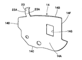
- the second shim 14 is integrally formed with a second claw portion 23 on the outer peripheral edge portion 14B in the disc radial direction.
- the second claw portion 23 is formed similarly to the inner claw 17 of the second claw portion 15 described in the first embodiment and constitutes a second claw portion. That is, the second claw portion 23 is integrally connected at the base end side to the outer peripheral edge portion 14B, and at the tip end side extending outward in the disk radial direction to form a free end.
- the second claw portion 23 is bent toward the outer peripheral edge portion 8B side of the plate 8, whereby the second shim 14 overlaps the first shim 11 and the first shim 11. Together, they are hooked to the outer peripheral edge portion 8B of the plate 8 via the second claw portion 23. That is, when the second shim 14 is press-molded, the second claw portion 23 is bent and formed toward the outer peripheral edge portion 8B of the plate 8. Then, when the second shim 14 is overlapped with the back surface side of the first shim 11, the second claw portion 23 together with the first claw portion 21 is elastically hooked to the outer peripheral edge portion 8B of the plate 8. It
- the second claw portion 23 is bent toward the outer peripheral edge portion 8B side of the plate 8 at a larger angle than the first claw portion 21.
- the side surface portion (that is, the outer side surface portion 23A) of the second pawl portion 23 in the direction orthogonal to the plate thickness direction of the pawl portion 23 and the inner side surface portion 21A of the first pawl portion 21 are in the disc circumferential direction. It is arranged at a position where they partially face each other. Therefore, even if the second shim 14 is displaced in the disc circumferential direction with respect to the first shim 11, the outer side surface portion 23A of the second claw portion 23 makes surface contact with the inner side surface portion 21A of the first claw portion 21. However, the occurrence of shim deviation can be suppressed.
- the outer surface portion 23A of the second claw portion 23 is formed. Comes into surface contact with the inner side surface portion 21A of the first claw portion 21, and it is possible to suppress the occurrence of the shim shift as in the first embodiment.
- the second claw portion 23 can be formed in a simpler shape than that of the first embodiment, and the second claw portion 23 can be easily manufactured. it can.
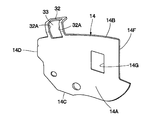
- FIG. 11 and FIG. 12 show a third embodiment, which is characterized in that the first claw portion is formed on the second shim and the second claw portion is formed on the first shim. It has a structure to be formed in.
- the same components as those in the first embodiment described above are designated by the same reference numerals, and the description thereof will be omitted.
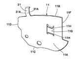
- the first shim 11 is integrally formed with the second claw portion 31 on the outer peripheral edge portion 11B in the disc radial direction.
- the second claw portion 31 is formed similarly to the inner claw 17 of the second claw portion 15 described in the first embodiment and constitutes a second claw portion. That is, the base end side of the second claw portion 31 is integrally connected to the outer peripheral edge portion 11B of the contact plate portion 11A, and the tip end side extends outward in the disc radial direction to be a free end.
- the second claw portion 31 is bent toward the outer peripheral edge portion 8B of the plate 8, so that the first shim 11 is prevented from coming off the outer peripheral edge portion 8B of the plate 8 via the second claw portion 31.
- the second claw portion 31 is formed by bending the first shim 11 toward the outer peripheral edge portion 8B of the plate 8 when the first shim 11 is press-formed.
- a side surface portion (that is, an outer side surface portion 31A) of the second pawl portion 31 in a direction orthogonal to the plate thickness direction of the pawl portion 31 is in a disc circumferential direction with an inner side surface portion 32A of a first pawl portion 32 described later. It is arranged at a position where they partially face each other.
- the second shim 14 is integrally formed with the first claw portion 32 on the outer peripheral edge portion 14B in the disc radial direction.
- the first claw portion 32 is formed as a substantially quadrangular frame-like body like the first claw portion 12 described in the first embodiment, and extends from the second shim 14 to the outer side in the disc radial direction. It constitutes one claw portion.
- a rectangular cutout 33 is formed as a punched hole near the center (that is, inside) of the first claw portion 32.
- the side surface portion (that is, the inner side surface portion 32A) of the first pawl portion 32 in the direction orthogonal to the plate thickness direction of the pawl portion 32 is a peripheral wall surface that surrounds the cutout portion 33 from the outside.
- the first claw portion 32 is bent toward the outer peripheral edge portion 8B side of the plate 8, so that the second shim 14 overlaps the first shim 11 and the first shim 11. Together, they are hooked to the outer peripheral edge portion 8B of the plate 8 via the first claw portion 32. That is, the first claw portion 32 is formed by bending toward the outer peripheral edge portion 8B of the plate 8 when press-forming the second shim 14. Then, when the second shim 14 is overlapped with the back surface side of the first shim 11, the first claw portion 32 is locked together with the second claw portion 31 to the outer peripheral edge portion 8B of the plate 8 in an elastically deformed state. It
- the first claw portion 32 is bent toward the outer peripheral edge portion 8B of the plate 8 at a larger angle than the second claw portion 31.
- the side surface portion (that is, the inner side surface portion 32A) of the first pawl portion 32 in the direction orthogonal to the plate thickness direction of the pawl portion 32 is in the disc circumferential direction with the outer side surface portion 31A of the second pawl portion 31. It is arranged at a position where they partially face each other. Therefore, even if the second shim 14 is displaced in the disc circumferential direction with respect to the first shim 11, the inner side surface portion 32A of the first claw portion 32 makes surface contact with the outer side surface portion 31A of the second claw portion 31. However, the occurrence of shim deviation can be suppressed.
- the inner side surface portion 32A of the first claw portion 32 is formed. Comes into surface contact with the outer side surface portion 23A of the second claw portion 31, and it is possible to suppress the occurrence of the shim shift as in the first embodiment.
- the second claw portion 31 can be formed in a simple shape, and the second claw portion 31 can be easily manufactured.
- the case where the second shim 14 is stacked on the first shim 11 is described as an example.
- the configuration is not limited to the case where the two shims are simply stacked and used, and the first and second shims are laminated by, for example, adhering the second shim to the first shim using an adhesive material. Good.
- the piston 6 is slidably provided in the inner leg portion 3A of the caliper 3 through the cylinder hole 5, and the outer friction pad 7 is pressed by the outer leg portion 3C of the caliper 3.
- the so-called floating caliper type disc brake has been described as an example.
- the present invention is not limited to this, and can be applied to, for example, a so-called opposed piston type disc brake in which pistons are provided on the inner side and the outer side of the caliper.
- a disc brake the support member being arranged to straddle an outer peripheral side of the disc in the axial direction, and the disc brake being supported by the support member and being arranged to face each other on both sides of the disc.
- a first claw portion formed to extend outward in the disc radial direction from one of the first shim and the second shim, and the first shim.
- a cutout portion formed in the vicinity of the center of the claw portion and the other shim of the first shim and the second shim, extending outward in the disk radial direction, and arranged inside the cutout portion.
- a second claw portion wherein the first claw portion and the second claw portion are bent toward the plate side, and the first claw portion and the second claw portion are provided. Means that side surfaces of the first claw portion and the second claw portion in the direction orthogonal to the plate thickness direction are partially opposed to each other.
- a hole is formed in the second shim at a position separated from the claw portion, and one of the cutouts formed in the first shim.
- the portion is bent in the disc axial direction and inserted into the inner rule of the hole formed in the second shim.
- a third aspect is a friction pad, which includes a plate having a lining attached to contact with a disk and a shim, the shim being provided on a rear surface of the plate opposite to the lining.
- a first claw formed to extend outward in the disc radial direction from one of the second shim, a cutout formed near the center of the first claw, and the first claw
- the first shim and the second shim, the second claw is formed to extend outward in the disc radial direction from the other shim, and the second claw is disposed inside the cutout portion.
- the claw part and the second claw part are bent toward the plate side, and the first claw part and the second claw part are the first claw part and the second claw part.
- the side surface portions in the direction orthogonal to the plate thickness direction of the are partially opposed to each other.
- a fourth aspect is a shim, wherein a first shim provided on the back surface of the plate of the friction pad on the opposite side to the lining and a plate of the first shim opposite the plate.
- a second shim provided to overlap with the first shim and one of the first shim and the second shim on the back surface of the side extending outward in the disk radial direction.
- a first claw portion formed, a cutout portion formed in the vicinity of the center of the first claw portion, and the other shim of the first shim and the second shim outward from the disk radial direction.
- a second claw portion that is formed to extend to the inside of the cutout portion, and the first claw portion and the second claw portion are bent toward the plate side, In the first claw portion and the second claw portion, side surface portions of the first claw portion and the second claw portion in a direction orthogonal to the plate thickness direction are partially opposed to each other. There is.
- the present invention is not limited to the above-described embodiment, and various modifications are included.
- the above-described embodiments have been described in detail in order to explain the present invention in an easy-to-understand manner, and are not necessarily limited to those including all the configurations described.
- a part of the configuration of one embodiment can be replaced with the configuration of another embodiment, and the configuration of another embodiment can be added to the configuration of one embodiment.
Landscapes
- Engineering & Computer Science (AREA)
- General Engineering & Computer Science (AREA)
- Mechanical Engineering (AREA)
- Braking Arrangements (AREA)
Abstract
摩擦パッドのプレートに固定される第1のシムには、第1のシムの外周縁部からディスク径方向外方に延びて形成された第1爪部と、第1爪部の中央付近に形成された切抜き部とを設けている。一方、第1のシムの外側に重ね合わせて配置される第2のシムには、当該シムからディスク径方向外方に延びて形成され、第1のシムの第1爪部に対し外側から重なり合うように配置される第2爪部を設けている。第2爪部は、第1爪部の切抜き部の内側に配置される内爪を備えている。
Description
本発明は、例えば車両等に制動力を与えるのに好適に用いられるディスクブレーキ、摩擦パッドおよびシムに関する。
一般に、ディスクブレーキは、自動車等の車両に用いられ、車輪と共に回転するディスクに摩擦パッドを押圧することによって車両に制動力を付与する構成としている(例えば、特許文献1,2参照)。このようなディスクブレーキには、ディスクの両面(インナ側とアウタ側)に一対の摩擦パッドが設けられ、各摩擦パッドの裏面には、薄い金属板等によって形成され2枚重ね(積層状態)で配置される内側のシムと外側のシムとが設けられている。この場合、内側のシムと外側のシムには、2つのシムが相対移動するのを防ぐために位置ずれ防止用の爪部が設けられている。
ところで、上述した従来技術では、外側のシムが内側のシムに対して相対移動を繰返すうちに、位置ずれ防止用の爪部が損傷することがあり、両者の相対移動を必ずしも十分には抑制することができないという問題がある。
本発明の目的は、シムの位置ずれを防止し、ブレーキ性能を向上することができるようにしたディスクブレーキ、摩擦パッドおよびシムを提供することにある。
本発明の一実施形態によるディスクブレーキは、ディスクの外周側を軸方向に跨いで配置される支持部材と、前記支持部材に支持され前記ディスクの両面に対向配置される一対の摩擦パッドと、前記一対の摩擦パッドを前記ディスクに押圧する押圧機構とを備え、前記摩擦パッドは、前記ディスクに接触するライニングが取付けられたプレートと、シムとを備え、前記シムは、前記プレートの両面のうち前記ライニングとは反対側の裏面に設けられる第1のシムと、前記第1のシムの両面のうち前記プレートとは反対側の裏面に、前記第1のシムと重合わせて設けられる第2のシムと、前記第1のシムと前記第2のシムとのうちいずれか一方のシムからディスク径方向外方に延びて形成された第1の爪部と、前記第1の爪部の中央付近に形成された切抜き部と、前記第1のシムと前記第2のシムとのうち他方のシムからディスク径方向外方に延びて形成され、前記切抜き部の内側に配置される第2の爪部とを有し、前記第1の爪部および前記第2の爪部は、前記プレート側に折曲げられており、前記第1の爪部と前記第2の爪部とは、前記第1の爪部および前記第2の爪部の板厚方向に対して直交する方向の側面部同士が部分的に対向している。
また、本発明の一実施形態による摩擦パッドは、ディスクに接触するライニングが取付けられたプレートと、シムとを備え、前記シムは、前記プレートの両面のうち前記ライニングとは反対側の裏面に設けられる第1のシムと、前記第1のシムの両面のうち前記プレートとは反対側の裏面に、前記第1のシムと重合わせて設けられる第2のシムと、前記第1のシムと前記第2のシムとのうちいずれか一方のシムからディスク径方向外方に延びて形成された第1の爪部と、前記第1の爪部の中央付近に形成された切抜き部と、前記第1のシムと前記第2のシムとのうち他方のシムからディスク径方向外方に延びて形成され、前記切抜き部の内側に配置された第2の爪部とを有し、前記第1の爪部および前記第2の爪部は、前記プレート側に折曲げられており、前記第1の爪部と前記第2の爪部とは、前記第1の爪部および前記第2の爪部の板厚方向に対して直交する方向の側面部同士が部分的に対向している。
さらに、本発明の一実施形態によるシムは、摩擦パッドのプレートの両面のうちライニングとは反対側の裏面に設けられる第1のシムと、前記第1のシムの両面のうち前記プレートとは反対側の裏面に、前記第1のシムと重合わせて設けられる第2のシムと、前記第1のシムと前記第2のシムとのうちいずれか一方のシムからディスク径方向外方に延びて形成された第1の爪部と、前記第1の爪部の中央付近に形成された切抜き部と、前記第1のシムと前記第2のシムとのうち他方のシムからディスク径方向外方に延びて形成され、前記切抜き部の内側に配置される第2の爪部とを有し、前記第1の爪部および前記第2の爪部は、前記プレート側に折曲げられており、前記第1の爪部と前記第2の爪部とは、前記第1の爪部および前記第2の爪部の板厚方向に対して直交する方向の側面部同士が部分的に対向している。
本発明の一実施形態によれば、第2のシムが第1のシムに対して位置ずれするのを抑えることができ、ブレーキ鳴き等の異音の発生を抑え、ブレーキ性能を向上させることができる。
以下、本発明の実施の形態として、4輪自動車等の車両に搭載されるディスクブレーキ、摩擦パッドおよびシムを例に挙げ、添付図面に従って詳細に説明する。
ここで、図1ないし図8は、第1の実施の形態を示している。図1において、支持部材1は車両の非回転部分(図示せず)に取付けられる当該ディスクブレーキの取付部材(キャリア)である。この支持部材1は、例えば車輪と共に回転するディスク2のインナ側とアウタ側とにわたって配置されている。なお、ディスク2は、例えば車両の前進時に図1中の矢示A方向に回転する。これにより、図1中の右側は、ディスク2の回転方向入口側(以下、回入側という)となり、左側は回転方向出口側(以下、回出側という)となる。
支持部材1は、ディスク2の周方向に離間してその外周側を跨ぐように軸方向に延びた一対の腕部1Aと、これらの腕部1Aを互いに連結すべくディスク周方向に延びた支承部1B(図2参照)と、補強ビーム1Cとにより一体物として形成されている。支持部材1の支承部1Bは、各腕部1Aの基端側を一体に連結するように厚肉に形成され、ディスク2のインナ側となる位置で車両の非回転部分に固定される。また、補強ビーム1Cは、ディスク2のアウタ側で各腕部1Aの先端側を互いに連結するようにディスク2の周方向に延びて形成されている。
支持部材1の各腕部1Aには、ディスク2のインナ側およびアウタ側に位置して凹形状に窪んだパッドガイド部(図示せず)が設けられている。これらのパッドガイド部は、後述のパッドスプリング19と協働して一対の摩擦パッド7をディスク2の軸方向に案内する。換言すると、支持部材1の各腕部1Aは、ディスク2の両面に対向配置される一対の摩擦パッド7をディスク軸方向に摺動可能に支持するために前記パッドガイド部を有している。
キャリパ3は、一対の摩擦パッド7をディスク2に押圧する押圧機構を、後述のシリンダ穴5およびピストン6と共に構成している。キャリパ3は、支持部材1の各腕部1Aに摺動可能に支持され、ディスク2の外周を跨ぐように配設されている。キャリパ3は、インナ脚部3Aと、ブリッジ部3Bと、アウタ脚部3Cと、一対の取付部3Dとを含んで構成されている。
キャリパ3のインナ脚部3Aは、ディスク2のインナ側に配置され、インナ脚部3Aには後述のシリンダ穴5とピストン6とが設けられている。キャリパ3のブリッジ部3Bは、インナ脚部3Aからディスク2の外周側を跨ぐようにアウタ側に延びている。アウタ脚部3Cは、ブリッジ部3Bの先端側からディスク径方向内向きに延びてディスク2のアウタ側に配置され、先端側が二又状の爪部となって形成されている。
一対の取付部3Dは、図1に示す如く、キャリパ3のインナ脚部3Aからディスク周方向(回転方向)両側へと互いに逆向きに延びるように形成されている。これらの取付部3Dには、それぞれ摺動ピン4が固定して設けられている。これらの摺動ピン4は、その先端側が支持部材1の各腕部1A(ピン穴)内に向けてディスク軸方向に延びている。各摺動ピン4の先端側は、支持部材1の各腕部1A(ピン穴)内に摺動可能に挿嵌されている。これにより、キャリパ3は、これらの摺動ピン4を介して支持部材1の各腕部1Aにディスク軸方向で摺動可能に支持されている。
インナ脚部3A内には、例えば2個のシリンダ穴5(図2に一方のみ図示)がディスク2の周方向(回転方向)方向に並んで設けられている。これらのシリンダ穴5内には、ピストン6がそれぞれ摺動可能に挿嵌されている。また、各取付部3Dは、摺動ピン4(図1参照)を用いて支持部材1の各腕部1Aにそれぞれ取付けられている。これにより、キャリパ3は、ディスク2の軸方向において摺動変位可能となっている。
各ピストン6は、キャリパ3の各シリンダ穴5内にそれぞれ摺動可能に挿嵌されている。ここで、各ピストン6は、それぞれ有底円筒状に形成され、その突出端側は、後述のシム14と当接(接触)する円環状の環状接触部6Aとなっている。ピストン6の環状接触部6Aは、後述するインナ側の摩擦パッド7(プレート8)の外縁(周縁)内に収まる(はみ出ない)大きさとなっている。そして、各ピストン6は、各シリンダ穴5内にブレーキ液圧が供給されることにより、インナ側の摩擦パッド7をディスク2に押圧するものである。
即ち、ブレーキの作動時に、キャリパ3の各シリンダ穴5内にブレーキ液圧が供給されると、各ピストン6がディスク軸方向に移動して、各ピストン6の環状接触部6Aによってインナ側の摩擦パッド7がディスク2に押圧される。このとき、キャリパ3は、各ピストン6からの反力によってインナ側へとディスク軸方向に変位する。これにより、アウタ脚部3Cがアウタ側の摩擦パッド7をディスク2に押圧する。この結果、ディスク2の両面には、夫々の摩擦パッド7が押圧されて車両に制動力を付与することができる。
一対の摩擦パッド7は、支持部材1の各腕部1Aにより前記パッドガイド部を介して支持され、ディスク2の両面側(即ち、インナ側とアウタ側)に対向配置されている。このうち、インナ側の摩擦パッド7は、図2に示す如く、キャリパ3(インナ脚部3A側)のピストン6とディスク2との間に配置され、アウタ側の摩擦パッド7は、キャリパ3のアウタ脚部3Cとディスク2との間に配置されている。
各摩擦パッド7は、例えば裏金と呼ばれる裏板としてのプレート8と、該プレート8の表面側に接合(固着)して設けられ、ディスク2に摩擦接触するライニング9と、プレート8の両面のうちライニング9とは反対側の裏面に配置される積層シム10とを含んで構成されている。この積層シム10は、プレート8の両面のうちライニング9とは反対側の裏面に設けられる第1のシム11と、第1のシム11の両面のうちプレート8とは反対側の裏面に積層するように重合わせて設けられる第2のシム14とから構成されている。
ここで、プレート8は、図3に示す如く、ディスク2の周方向(回転方向)に延びる略扇形状の金属板(板体)によって形成され、その両端側には略四角形状の突部8A,8Aが一体に設けられている。そして、摩擦パッド7は、各突部8Aが後述のパッドスプリング19を介して支持部材1の各腕部1A(パッドガイド部)に摺動可能に嵌合され、これらの腕部1A(パッドガイド部)の間でディスク2の軸方向に変位可能となるように、支持部材1により支持されている。
また、プレート8は、ディスク径方向の外側寄りに位置する外周縁部8Bと、ディスク径方向の内側寄りに位置する内周縁部8Cと、これらの外,内周縁部8B,8Cの間でディスク周方向両側に位置する一側(例えば、回入側)の側縁部8Dと他側(例えば、回出側)の側縁部8Eとを含んで構成されている。プレート8の各突部8Aは、一側と他側の側縁部8D,8Eからディスク周方向両側に向けて突出した耳部として形成されている。
プレート8の外周縁部8Bは、周方向の中間部に位置する凹部8B1を基準として左,右対称な円弧形状(例えば、ディスク2の外径に対応した円弧形状)をなす縁部として形成されている。また、プレート8の内周縁部8Cには、各突部8Aから一定寸法離間した位置に左,右一対の取付凹部8C1が形成され、これらの取付凹部8C1には、後述するシム11,14の各折曲げ部11J,14Hが係止される。
次に、摩擦パッド7のプレート8に取付けられる積層シム10(即ち、第1,第2のシム11,14)について、図3~図8を参照して説明する。
第1のシム11は、摩擦パッド7のプレート8に当接(面接触)状態で取付けられる内側の固定シムである。第1のシム11は、例えばばね性を有する金属板(ステンレス鋼板)等をプレス加工することにより形成され、その表面には、例えば硬質ゴム、合成樹脂等の材料からなる被膜(図示せず)がコーティングされている。なお、この被膜は必ずしも設ける必要はなく、場合によっては、例えば鋼板等の金属板をそのまま第1のシム11として用いてもよい。
そして、第1のシム11は、図3、図4~図7に示す如く、ディスク2の周方向に延びる略扇形状の平板として形成された当接板部11Aと、該当接板部11Aのうちディスク径方向の外側寄りに位置する外周縁部11Bと、ディスク径方向の内側寄りに位置する内周縁部11Cと、これらの外,内周縁部11B,11Cの間でディスク周方向両側に位置する一側(例えば、回入側)の側縁部11Dと他側(例えば、回出側)の側縁部11Eとを含んで構成されている。
第1のシム11には、当接板部11Aの左,右方向中間部に位置し、ディスク径方向の外周縁部11Bに開口するコ字形状の中央切欠き部11Fと、該中央切欠き部11Fから左,右方向に離間して当接板部11Aに形成された略四角形の開口部11Gと、切欠き穴からなる開口部11Gの上,下両端部(即ち、切欠きの一部)をディスク軸方向へとL字状に折曲げて形成された上,下の屈曲片部11H,11Hと、ディスク径方向内側の内周縁部11Cに形成された左,右の折曲げ部11Jとが設けられている。
ここで、第1のシム11には、ディスク径方向の外周縁部11Bに一対の第1爪部12が一体に形成されている。一対の第1爪部12は、図3に示すように、中央切欠き部11Fからディスク周方向に離間して左,右対称となる位置に配置されている。また、一対の第1爪部12は、図3に示すように、左,右の側縁部11D,11Eからもディスク周方向に離間し、その周方向位置は、左,右の側縁部11D,11Eに相対的に近く、中央切欠き部11Fからは相対的に大きく離間した位置となっている。
第1爪部12は、第1のシム11からディスク径方向外方に延びて形成された第1の爪部を構成し、図7に示すように、略四角形の枠状体となっている。このため、第1爪部12の中央付近(即ち、内側)には、四角形状の切抜き部13が打抜き穴として形成されている。第1爪部12のうち当該爪部の板厚方向に対して直交する方向の側面部(即ち、内側面部12A)は、切抜き部13を外側から取り囲んだ周壁面となっている。この内側面部12Aは、例えば図5に示す如く第1のシム11と第2のシム14とを重ね合わせたときに、後述する内爪17の外側面部17Aとディスク周方向で部分的に対向する位置に配置される。
第1爪部12は、図5、図6に示すように、プレート8の外周縁部8B側に折曲げられており、これにより、第1のシム11は、プレート8の外周縁部8Bに第1爪部12を介して抜止めされる。即ち、第1爪部12は、第1のシム11をプレス成形するときに、図5~図7に示すように、プレート8の外周縁部8B側に折曲げて成形される。
そして、第1のシム11をプレート8の裏面側に重合わせるときには、第1爪部12がプレート8の外周縁部8Bに弾性変形状態で係合される。また、第1のシム11の各折曲げ部11Jは、プレート8の内周縁部8Cに形成された左,右の取付凹部8C1にそれぞれ係合される。これにより、第1のシム11は、プレート8の裏面側に重合わせた状態で、該プレート8に対して抜止め状態で固定される。
次に、第2のシム14は、第1のシム11の両面のうちプレート8とは反対側の裏面に重合わせて設けられる外側のシムである。第2のシム14は、第1のシム11と同様に、例えばばね性を有する金属板(ステンレス鋼板)等をプレス加工することにより形成され、その表面には、例えば硬質ゴム、合成樹脂等の材料からなる被膜(図示せず)がコーティングされている。なお、この被膜は必ずしも設ける必要はなく、場合によっては、例えば鋼板等の金属板をそのまま第2のシム14として用いてもよい。
そして、第2のシム14は、前述した第1のシム11と同様に、当接板部14A、外周縁部14B、内周縁部14C、一側の側縁部14D、他側の側縁部14Eおよびコ字形状の中央切欠き部14Fを備えている。また、第2のシム14の当接板部14Aには、中央切欠き部14Fから左,右方向に離間した位置に略四角形の開口部14Gが形成されている。この開口部14Gには、第2のシム14を第1のシム11上に重合わせたときに、図3、図4に示す如く、第1のシム11の各屈曲片部11Hが挿入される。
即ち、第1のシム11の各屈曲片部11Hは、第1のシム11に形成された切欠き(開口部11G)の一部がディスク軸方向に折曲げられて形成されている。そして、第2のシム14に形成された穴(即ち、開口部14G)の内則には、第1のシム11の各屈曲片部11Hが挿入される。これにより、第2のシム14は、開口部14Gの周壁側が各屈曲片部11Hに係合し、第1のシム11に対する第2のシム14の相対移動が抑えられる。
また、第2のシム14には、ディスク径方向内側の内周縁部14Cに左,右の折曲げ部14Hが形成されている。これらの折曲げ部14Hは、第1のシム11の各折曲げ部11Jと同様に形成され、プレート8の各取付凹部8C1には、これらの各折曲げ部11J,14Hが係合される。このとき、第2のシム14の各折曲げ部14Hは、第1のシム11の各折曲げ部11Jを外側から覆うように、折曲げ部11Jに上側から重合わせて取付けられる。
ここで、第2のシム14には、ディスク径方向の外周縁部14Bに一対の第2爪部15が一体に形成されている。一対の第2爪部15は、図3に示すように、中央切欠き部14Fからディスク周方向に離間して左,右対称となる位置に配置されている。また、一対の第2爪部15は、図3に示すように、左,右の側縁部14D,14Eからもディスク周方向に離間し、その周方向位置は、左,右の側縁部14D,14Eに相対的に近く、中央切欠き部14Fからは相対的に大きく離間した位置となっている。第2のシム14の各第2爪部15は、図3、図4に示す如く、第1のシム11の各第1爪部12とほぼ同一の位置で互いに重なり合うように形成されている。
しかし、第2のシム14の第2爪部15は、第2のシム14からディスク径方向外方に延びて形成された枠状爪16と内爪17とにより構成されている。第2爪部15の枠状爪16は、前述した第1爪部12と同様に略四角形の枠状体として形成されている。第2爪部15の中央付近(即ち、枠状爪16の内側)には、内爪17を残して略コ字形状(四角形状)に切欠いて形成された切欠き部18が設けられている。この切欠き部18は、枠状爪16の内側で内爪17の周囲を縁取って、外側から取り囲むように形成されている。換言すると、第2のシム14の第2爪部15は、仮に内爪17を取除いた場合には第1のシム11の第1爪部12と実質的に同一な形状となるように形成されている。
第2爪部15の内爪17は、第2のシム14の外周縁部14Bからディスク径方向外方に延びて形成され、第1爪部12(切抜き部13)と切欠き部18との内側に配置される第2の爪部を構成している。内爪17は、切欠き部18の内側に位置して基端側が外周縁部14Bに一体に連結され、先端側がディスク径方向外方に延びている。内爪17の先端は、枠状爪16の先端側と切欠き部18を挟んで対向する自由端となっている。
第2爪部15の枠状爪16と内爪17とは、図6、図8に示すように、プレート8の外周縁部8B側に折曲げられており、これにより、第2のシム14は、第1のシム11と重ね合わせた状態で、第1のシム11と一緒にプレート8の外周縁部8Bに第2爪部15を介して掛止めされる。即ち、第2爪部15の枠状爪16と内爪17とは、第2のシム14をプレス成形するときに、図6、図8に示すように、プレート8の外周縁部8B側に折曲げて成形される。そして、第2のシム14を第1のシム11の裏面側に重ね合せるときには、第2爪部15が第1爪部12と一緒にプレート8の外周縁部8Bに弾性変形状態で掛止めされる。
この場合、第2爪部15の内爪17は、枠状爪16よりも大きな角度でプレート8の外周縁部8B側に折曲げられている。これにより、第2爪部15の内爪17のうち、当該内爪17の板厚方向に対して直交する方向の側面部(即ち、外側面部17A)は、第1爪部12の内側面部12Aとディスク周方向で部分的に対向する位置に配置されている。このため、第2のシム14が第1のシム11に対してディスク周方向に位置ずれしても、内爪17の外側面部17Aは、第1爪部12の内側面部12Aに面接触し、シムずれの発生を抑えることができる。
なお、支持部材1の各腕部1A(パッドガイド部)には、例えば図1に示すように、一対のパッドスプリング19が各摩擦パッド7との間に介在して設けられている。これらのパッドスプリング19は、摩擦パッド7(プレート8の突部8A)を腕部1A(パッドガイド部)内でディスク軸方向に摺動可能に案内するものである。
第1の実施の形態によるディスクブレーキは、上述の如き構成を有するもので、次に、その作動について説明する。
まず、ブレーキペダル(図示せず)が踏込み操作されたときには、キャリパ3のシリンダ穴5内にブレーキ液圧が供給され、ピストン6がインナ側の摩擦パッド7に向けて変位する。これにより、ピストン6は摩擦パッド7をディスク2に押圧し、このときの反力によってキャリパ3がインナ側に変位する。この結果、キャリパ3のアウタ脚部3Cは、アウタ側の摩擦パッド7をディスク2に押圧するようになるので、各摩擦パッド7によってディスク2に両側から制動力を付与することができる。
また、このようなブレーキ作動時には、ピストン6の押圧力が第1,第2のシム11,14の当接板部11A,14Aを介してインナ側の摩擦パッド7(プレート8)に伝達される。また、アウタ側の摩擦パッド7(プレート8)には、キャリパ3のアウタ脚部3Cからの押圧力が第1,第2のシム11,14の当接板部11A,14Aを介して伝達される。そして、インナ側とアウタ側の摩擦パッド7は、ディスク2の両面に摩擦接触することにより、ディスク回転方向のトルクを受ける。このため、パッド外側のシム(第2のシム14)は、内側のシム(第1のシム11)に対してディスク2の回転方向に相対移動するような外力を受けることになる。
これに対し、従来技術のディスクブレーキでは、内側のシムと外側のシムとの間に位置ずれ防止用の爪部が設けられている。しかし、このような従来技術では、外側のシムが内側のシムに対して相対移動を繰返すうちに、位置ずれ防止用の爪部が損傷することがあり、両者の相対移動を必ずしも十分には抑制することができない。
そこで、第1の実施の形態では、摩擦パッド7のプレート8に固定される第1のシム11には、当該シム11の外周縁部11Bからディスク径方向外方に延びて形成された第1爪部12(第1の爪部)と、第1爪部12の中央付近に形成された切抜き部13とを設けている。一方、第1のシム11の外側に重ね合わせて配置される第2のシム14には、当該シム14からディスク径方向外方に延びて形成され、第1のシム11の第1爪部12に対し外側から重なり合うように配置される第2爪部15を設けている。
ここで、第2のシム14の第2爪部15は、第2のシム14からディスク径方向外方に延びて形成された枠状爪16と内爪17とにより構成され、この内爪17は、第1爪部12の切抜き部13の内側に配置される第2の爪部として形成されている。第2爪部15の枠状爪16は、前述した第1爪部12と同様に略四角形の枠状体として形成されている。第2爪部15の中央付近(即ち、枠状爪16の内側)には、内爪17を残して略コ字形状(四角形状)に切欠いて形成された切欠き部18が設けられている。この切欠き部18により、内爪17は、枠状爪16に対して異なる角度でプレート8の外周縁部8B側に折曲げられ、かつ異なる角度をもって変位可能となっている。
そして、第1爪部12および第2爪部15は、プレート8の外周縁部8B側に折曲げられており、第1爪部12と第2爪部15の内爪17とは、当該爪部の板厚方向に対して直交する方向の側面部(即ち、内側面部12Aと外側面部17Aと)がディスク周方向で部分的に対向する位置に配置されている。
このため、ブレーキ操作を繰返す度毎に、外側の第2のシム14が内側のシム(第1のシム11)に対してディスク2の回転方向に相対移動するような外力を受け、仮に第2のシム14が第1のシム11に対してディスク周方向に位置ずれしても、内爪17の外側面部17Aは、第1爪部12の内側面部12Aに面接触し、シムずれの発生を抑えることができる。第1爪部12は、摩擦パッド7のプレート8に固定されているので、内爪17(第2の爪部)のディスク周方向への変位を抑え、ずれ防止効果を発揮できる。
しかも、第1爪部12と第2爪部15(特に、内爪17)とは、プレート8側への折曲げ角が異なっているので、ディスク周方向(半径方向)回転モーメントによるシムずれが発生する場合でも、第1爪部12と第2爪部15(特に、内爪17)とがディスク周方向で干渉し合い、これ以上にシムずれ量が大きくなるのを抑えることができる。
また、第1のシム11には、中央切欠き部11Fから左,右方向に離間して当接板部11Aに形成された略四角形の開口部11Gと、切欠き穴からなる開口部11Gの上,下両端部(即ち、切欠きの一部)をディスク軸方向へとL字状に折曲げて形成された上,下の屈曲片部11H,11Hとが設けられている。そして、第2のシム14に形成された穴(即ち、開口部14G)の内則には、第1のシム11の各屈曲片部11Hが挿入されている。これにより、第2のシム14は、開口部14Gの周壁側が各屈曲片部11Hに係合し、第1のシム11に対する第2のシム14の相対移動が抑えられる。
従って、第1の実施の形態によれば、第1のシム11に対する第2のシム14の位置ずれを防止でき、ブレーキ鳴き等の異音の発生を抑え、ブレーキ性能を向上させることができる。また、第1爪部12と第2爪部15(特に、内爪17)とがディスク周方向で干渉し合うことによる損傷を、長期にわたって抑えることができ、耐久性、寿命を向上させることができる。
次に、図9および図10は第2の実施の形態を示し、本実施の形態の特徴は、第2の爪部をより簡素な形状に形成したことにある。なお、第2の実施の形態では、前述した第1の実施の形態と同一の構成要素に同一の符号を付し、その説明を省略するものとする。
ここで、第1のシム11には、図9に示すように、ディスク径方向の外周縁部11Bに第1爪部21が一体に形成されている。この第1爪部21は、第1の実施の形態で述べた第1爪部12と同様に略四角形の枠状体として形成され、第1のシム11からディスク径方向外方に延びた第1の爪部を構成している。第1爪部21の中央付近(即ち、内側)には、四角形状の切抜き部22が打抜き穴として形成されている。第1爪部21のうち当該爪部の板厚方向に対して直交する方向の側面部(即ち、内側面部21A)は、切抜き部22を外側から取り囲んだ周壁面となっている。
また、第2のシム14には、図10に示すように、ディスク径方向の外周縁部14Bに第2爪部23が一体に形成されている。この第2爪部23は、第1の実施の形態で述べた第2爪部15の内爪17と同様に形成され、第2の爪部を構成している。即ち、第2爪部23は、基端側が外周縁部14Bに一体に連結され、先端側はディスク径方向外方に延びて自由端となっている。
第2爪部23は、プレート8の外周縁部8B側に折曲げられており、これにより、第2のシム14は、第1のシム11と重ね合わせた状態で、第1のシム11と一緒にプレート8の外周縁部8Bに第2爪部23を介して掛止めされる。即ち、第2爪部23は、第2のシム14をプレス成形するときに、プレート8の外周縁部8B側に折曲げて成形される。そして、第2のシム14を第1のシム11の裏面側に重ね合せるときには、第2爪部23が第1爪部21と一緒にプレート8の外周縁部8Bに弾性変形状態で掛止めされる。
この場合、第2爪部23は、第1爪部21よりも大きな角度でプレート8の外周縁部8B側に折曲げられている。これにより、第2爪部23のうち、当該爪部23の板厚方向に対して直交する方向の側面部(即ち、外側面部23A)は、第1爪部21の内側面部21Aとディスク周方向で部分的に対向する位置に配置されている。このため、第2のシム14が第1のシム11に対してディスク周方向に位置ずれしても、第2爪部23の外側面部23Aは、第1爪部21の内側面部21Aに面接触し、シムずれの発生を抑えることができる。
かくして、このように構成される第2の実施の形態でも、仮に第2のシム14が第1のシム11に対してディスク周方向に位置ずれしても、第2爪部23の外側面部23Aが第1爪部21の内側面部21Aに面接触し、前記第1の実施の形態と同様にシムずれの発生を抑えることができる。特に、第2の実施の形態にあっては、第2爪部23を第1の実施の形態よりも簡素な形状に形成することができ、第2爪部23の製作を容易に行うことができる。
次に、図11および図12は第3の実施の形態を示し、本実施の形態の特徴は、第1の爪部を第2のシムに形成し,第2の爪部を第1のシムに形成する構成としたことにある。なお、第3の実施の形態では、前述した第1の実施の形態と同一の構成要素に同一の符号を付し、その説明を省略するものとする。
ここで、第1のシム11には、図11に示すように、ディスク径方向の外周縁部11Bに第2爪部31が一体に形成されている。この第2爪部31は、第1の実施の形態で述べた第2爪部15の内爪17と同様に形成され、第2の爪部を構成している。即ち、第2爪部31は、基端側が当接板部11Aの外周縁部11Bに一体に連結され、先端側はディスク径方向外方に延びて自由端となっている。
第2爪部31は、プレート8の外周縁部8B側に折曲げられており、これにより、第1のシム11は、プレート8の外周縁部8Bに第2爪部31を介して抜止めされる。即ち、第2爪部31は、第1のシム11をプレス成形するときに、プレート8の外周縁部8B側に折曲げて成形される。第2爪部31のうち、当該爪部31の板厚方向に対して直交する方向の側面部(即ち、外側面部31A)は、後述する第1爪部32の内側面部32Aとディスク周方向で部分的に対向する位置に配置されている。
また、第2のシム14には、図12に示すように、ディスク径方向の外周縁部14Bに第1爪部32が一体に形成されている。この第1爪部32は、第1の実施の形態で述べた第1爪部12と同様に略四角形の枠状体として形成され、第2のシム14からディスク径方向外方に延びた第1の爪部を構成している。第1爪部32の中央付近(即ち、内側)には、四角形状の切抜き部33が打抜き穴として形成されている。第1爪部32のうち当該爪部32の板厚方向に対して直交する方向の側面部(即ち、内側面部32A)は、切抜き部33を外側から取り囲んだ周壁面となっている。
第1爪部32は、プレート8の外周縁部8B側に折曲げられており、これにより、第2のシム14は、第1のシム11と重ね合わせた状態で、第1のシム11と一緒にプレート8の外周縁部8Bに第1爪部32を介して掛止めされる。即ち、第1爪部32は、第2のシム14をプレス成形するときに、プレート8の外周縁部8B側に折曲げて成形される。そして、第2のシム14を第1のシム11の裏面側に重ね合せるときには、第1爪部32が第2爪部31と一緒にプレート8の外周縁部8Bに弾性変形状態で掛止めされる。
この場合、第1爪部32は、第2爪部31よりも大きな角度でプレート8の外周縁部8B側に折曲げられている。これにより、第1爪部32のうち、当該爪部32の板厚方向に対して直交する方向の側面部(即ち、内側面部32A)は、第2爪部31の外側面部31Aとディスク周方向で部分的に対向する位置に配置されている。このため、第2のシム14が第1のシム11に対してディスク周方向に位置ずれしても、第1爪部32の内側面部32Aは、第2爪部31の外側面部31Aに面接触し、シムずれの発生を抑えることができる。
かくして、このように構成される第3の実施の形態でも、仮に第2のシム14が第1のシム11に対してディスク周方向に位置ずれしても、第1爪部32の内側面部32Aが第2爪部31の外側面部23Aに面接触し、前記第1の実施の形態と同様にシムずれの発生を抑えることができる。特に、第3の実施の形態では、第2爪部31を簡素な形状に形成することができ、第2爪部31の製作を容易に行うことができる。
なお、前記各実施の形態では、第2のシム14を第1のシム11に重ね合わせて積層する場合を例に挙げて説明した。しかし、2つのシムを単に重ね合わせて用いる場合に限らず、例えば第1のシムに接着材を用いて第2のシムを接着することにより、第1,第2のシムを積層化する構成としてもよい。
また、前記各実施の形態では、キャリパ3のインナ脚部3Aに2個のピストン6を設ける構成とした場合を例に挙げて説明した。しかし、本発明はこれに限らず、例えば、キャリパのインナ脚部に1個または3個以上のピストンを設ける構成としてもよい。
また、前記各実施の形態では、キャリパ3のインナ脚部3Aにシリンダ穴5を介してピストン6を摺動可能に設け、キャリパ3のアウタ脚部3Cによりアウタ側の摩擦パッド7を押圧する構成とした所謂フローティングキャリパ型のディスクブレーキを例に挙げて説明した。しかし、本発明はこれに限らず、例えばキャリパのインナ側とアウタ側とにそれぞれピストンを設ける構成とした所謂対向ピストン型のディスクブレーキにも適用することができる。
次に、前記各実施の形態に含まれる発明について記載する。即ち、本発明の第1の態様としては、ディスクブレーキであって、ディスクの外周側を軸方向に跨いで配置される支持部材と、前記支持部材に支持され前記ディスクの両面に対向配置される一対の摩擦パッドと、前記一対の摩擦パッドを前記ディスクに押圧する押圧機構とを備え、前記摩擦パッドは、前記ディスクに接触するライニングが取付けられたプレートと、シムとを備え、前記シムは、前記プレートの両面のうち前記ライニングとは反対側の裏面に設けられる第1のシムと、前記第1のシムの両面のうち前記プレートとは反対側の裏面に、前記第1のシムと重合わせて設けられる第2のシムと、前記第1のシムと前記第2のシムとのうちいずれか一方のシムからディスク径方向外方に延びて形成された第1の爪部と、前記第1の爪部の中央付近に形成された切抜き部と、前記第1のシムと前記第2のシムとのうち他方のシムからディスク径方向外方に延びて形成され、前記切抜き部の内側に配置される第2の爪部とを有し、前記第1の爪部および前記第2の爪部は、前記プレート側に折曲げられており、前記第1の爪部と前記第2の爪部とは、前記第1の爪部および前記第2の爪部の板厚方向に対して直交する方向の側面部同士が部分的に対向している。
また、第2の態様としては、前記第1の態様において、前記第2のシムには、前記爪部から離間した位置に穴が形成され、前記第1のシムに形成された切欠きの一部がディスク軸方向に折曲げられて前記第2のシムに形成された前記穴の内則に挿入されている。
第3の態様としては、摩擦パッドであって、ディスクに接触するライニングが取付けられたプレートと、シムとを備え、前記シムは、前記プレートの両面のうち前記ライニングとは反対側の裏面に設けられる第1のシムと、前記第1のシムの両面のうち前記プレートとは反対側の裏面に、前記第1のシムと重合わせて設けられる第2のシムと、前記第1のシムと前記第2のシムとのうちいずれか一方のシムからディスク径方向外方に延びて形成された第1の爪部と、前記第1の爪部の中央付近に形成された切抜き部と、前記第1のシムと前記第2のシムとのうち他方のシムからディスク径方向外方に延びて形成され、前記切抜き部の内側に配置された第2の爪部とを有し、前記第1の爪部および前記第2の爪部は、前記プレート側に折曲げられており、前記第1の爪部と前記第2の爪部とは、前記第1の爪部および前記第2の爪部の板厚方向に対して直交する方向の側面部同士が部分的に対向している。
第4の態様としては、シムであって、摩擦パッドのプレートの両面のうちライニングとは反対側の裏面に設けられる第1のシムと、前記第1のシムの両面のうち前記プレートとは反対側の裏面に、前記第1のシムと重合わせて設けられる第2のシムと、前記第1のシムと前記第2のシムとのうちいずれか一方のシムからディスク径方向外方に延びて形成された第1の爪部と、前記第1の爪部の中央付近に形成された切抜き部と、前記第1のシムと前記第2のシムとのうち他方のシムからディスク径方向外方に延びて形成され、前記切抜き部の内側に配置される第2の爪部とを有し、前記第1の爪部および前記第2の爪部は、前記プレート側に折曲げられており、前記第1の爪部と前記第2の爪部とは、前記第1の爪部および前記第2の爪部の板厚方向に対して直交する方向の側面部同士が部分的に対向している。
なお、本発明は上記した実施形態に限定されるものではなく、様々な変形例が含まれる。例えば、上記した実施形態は本発明を分かりやすく説明するために詳細に説明したものであり、必ずしも説明した全ての構成を備えるものに限定されるものではない。また、ある実施形態の構成の一部を他の実施形態の構成に置き換えることが可能であり、また、ある実施形態の構成に他の実施形態の構成を加えることも可能である。また、各実施形態の構成の一部について、他の構成の追加・削除・置換をすることが可能である。
本願は、2018年11月20日付出願の日本国特許出願第2018-217273号に基づく優先権を主張する。2018年11月20日付出願の日本国特許出願第2018-217273号の明細書、特許請求の範囲、図面、および要約書を含む全開示内容は、参照により本願に全体として組み込まれる。
1 支持部材 1A 腕部 2 ディスク 3 キャリパ(押圧機構) 6 ピストン(押圧機構) 7 摩擦パッド 8 プレート 9 ライニング 10 積層シム(シム) 11 第1のシム 11H 屈曲片部(切欠き部の一部) 12,21,32 第1爪部(第1の爪部) 12A,21A,32A 内側面部(側面部) 13,22,33 切抜き部 14 第2のシム 14G 開口部(穴) 15 第2爪部 16 枠状爪 17 内爪(第2の爪部) 17A,23A,31A 外側面部(側面部) 18 切欠き部 23,31 第2爪部(第2の爪部)
Claims (4)
- ディスクブレーキであって、
ディスクの外周側を軸方向に跨いで配置される支持部材と、
前記支持部材に支持され前記ディスクの両面に対向配置される一対の摩擦パッドと、
前記一対の摩擦パッドを前記ディスクに押圧する押圧機構とを備え、
前記摩擦パッドは、
前記ディスクに接触するライニングが取付けられたプレートと、
シムとを備え、
前記シムは、
前記プレートの両面のうち前記ライニングとは反対側の裏面に設けられる第1のシムと、
前記第1のシムの両面のうち前記プレートとは反対側の裏面に、前記第1のシムと重合わせて設けられる第2のシムと、
前記第1のシムと前記第2のシムとのうちいずれか一方のシムからディスク径方向外方に延びて形成された第1の爪部と、
前記第1の爪部の中央付近に形成された切抜き部と、
前記第1のシムと前記第2のシムとのうち他方のシムからディスク径方向外方に延びて形成され、前記切抜き部の内側に配置される第2の爪部とを有し、
前記第1の爪部および前記第2の爪部は、前記プレート側に折曲げられており、
前記第1の爪部と前記第2の爪部とは、前記第1の爪部および前記第2の爪部の板厚方向に対して直交する方向の側面部同士が部分的に対向しているディスクブレーキ。 - 請求項1に記載のディスクブレーキであって、
前記第2のシムには、前記爪部から離間した位置に穴が形成され、
前記第1のシムに形成された切欠きの一部がディスク軸方向に折曲げられて前記第2のシムに形成された前記穴の内則に挿入されているディスクブレーキ。 - 摩擦パッドであって、
ディスクに接触するライニングが取付けられたプレートと、
シムとを備え、
前記シムは、
前記プレートの両面のうち前記ライニングとは反対側の裏面に設けられる第1のシムと、
前記第1のシムの両面のうち前記プレートとは反対側の裏面に、前記第1のシムと重合わせて設けられる第2のシムと、
前記第1のシムと前記第2のシムとのうちいずれか一方のシムからディスク径方向外方に延びて形成された第1の爪部と、
前記第1の爪部の中央付近に形成された切抜き部と、
前記第1のシムと前記第2のシムとのうち他方のシムからディスク径方向外方に延びて形成され、前記切抜き部の内側に配置された第2の爪部とを有し、
前記第1の爪部および前記第2の爪部は、前記プレート側に折曲げられており、
前記第1の爪部と前記第2の爪部とは、前記第1の爪部および前記第2の爪部の板厚方向に対して直交する方向の側面部同士が部分的に対向している摩擦パッド。 - シムであって、
摩擦パッドのプレートの両面のうちライニングとは反対側の裏面に設けられる第1のシムと、
前記第1のシムの両面のうち前記プレートとは反対側の裏面に、前記第1のシムと重合わせて設けられる第2のシムと、
前記第1のシムと前記第2のシムとのうちいずれか一方のシムからディスク径方向外方に延びて形成された第1の爪部と、
前記第1の爪部の中央付近に形成された切抜き部と、
前記第1のシムと前記第2のシムとのうち他方のシムからディスク径方向外方に延びて形成され、前記切抜き部の内側に配置される第2の爪部とを有し、
前記第1の爪部および前記第2の爪部は、前記プレート側に折曲げられており、
前記第1の爪部と前記第2の爪部とは、前記第1の爪部および前記第2の爪部の板厚方向に対して直交する方向の側面部同士が部分的に対向しているシム。
Applications Claiming Priority (2)
| Application Number | Priority Date | Filing Date | Title |
|---|---|---|---|
| JP2018-217273 | 2018-11-20 | ||
| JP2018217273A JP2022024201A (ja) | 2018-11-20 | 2018-11-20 | ディスクブレーキ、摩擦パッドおよびシム |
Publications (1)
| Publication Number | Publication Date |
|---|---|
| WO2020105611A1 true WO2020105611A1 (ja) | 2020-05-28 |
Family
ID=70774012
Family Applications (1)
| Application Number | Title | Priority Date | Filing Date |
|---|---|---|---|
| PCT/JP2019/045198 Ceased WO2020105611A1 (ja) | 2018-11-20 | 2019-11-19 | ディスクブレーキ、摩擦パッドおよびシム |
Country Status (2)
| Country | Link |
|---|---|
| JP (1) | JP2022024201A (ja) |
| WO (1) | WO2020105611A1 (ja) |
Cited By (2)
| Publication number | Priority date | Publication date | Assignee | Title |
|---|---|---|---|---|
| US20220154790A1 (en) * | 2019-04-17 | 2022-05-19 | Hitachi Astemo, Ltd. | Disc brake and laminated shim |
| WO2024245509A1 (en) * | 2023-05-31 | 2024-12-05 | Meneta Holding A/S | Back plate for a disc brake assembly, a noise damping shim for a disc brake assembly and such disc brake assembly |
Citations (5)
| Publication number | Priority date | Publication date | Assignee | Title |
|---|---|---|---|---|
| JPS5695626U (ja) * | 1979-12-22 | 1981-07-29 | ||
| JPS6332987Y2 (ja) * | 1982-06-08 | 1988-09-02 | ||
| JPH03112143U (ja) * | 1990-03-02 | 1991-11-15 | ||
| JP2002364685A (ja) * | 2001-06-11 | 2002-12-18 | Hosei Brake Ind Ltd | 複数板材の位置決め構造 |
| JP2017003005A (ja) * | 2015-06-10 | 2017-01-05 | 株式会社アドヴィックス | ディスクブレーキ用パッド組立体 |
-
2018
- 2018-11-20 JP JP2018217273A patent/JP2022024201A/ja active Pending
-
2019
- 2019-11-19 WO PCT/JP2019/045198 patent/WO2020105611A1/ja not_active Ceased
Patent Citations (5)
| Publication number | Priority date | Publication date | Assignee | Title |
|---|---|---|---|---|
| JPS5695626U (ja) * | 1979-12-22 | 1981-07-29 | ||
| JPS6332987Y2 (ja) * | 1982-06-08 | 1988-09-02 | ||
| JPH03112143U (ja) * | 1990-03-02 | 1991-11-15 | ||
| JP2002364685A (ja) * | 2001-06-11 | 2002-12-18 | Hosei Brake Ind Ltd | 複数板材の位置決め構造 |
| JP2017003005A (ja) * | 2015-06-10 | 2017-01-05 | 株式会社アドヴィックス | ディスクブレーキ用パッド組立体 |
Cited By (3)
| Publication number | Priority date | Publication date | Assignee | Title |
|---|---|---|---|---|
| US20220154790A1 (en) * | 2019-04-17 | 2022-05-19 | Hitachi Astemo, Ltd. | Disc brake and laminated shim |
| US12110932B2 (en) * | 2019-04-17 | 2024-10-08 | Hitachi Astemo, Ltd. | Disc brake and laminated shim |
| WO2024245509A1 (en) * | 2023-05-31 | 2024-12-05 | Meneta Holding A/S | Back plate for a disc brake assembly, a noise damping shim for a disc brake assembly and such disc brake assembly |
Also Published As
| Publication number | Publication date |
|---|---|
| JP2022024201A (ja) | 2022-02-09 |
Similar Documents
| Publication | Publication Date | Title |
|---|---|---|
| CN102852999B (zh) | 盘式制动器 | |
| CN108291597B (zh) | 盘式制动器 | |
| US10619688B2 (en) | Disc Brake for vehicle | |
| JPWO2019049539A1 (ja) | 車両用ディスクブレーキ | |
| KR101922258B1 (ko) | 디스크 브레이크 | |
| JP7229343B2 (ja) | ディスクブレーキおよび積層シム | |
| CN108700148A (zh) | 盘式制动器 | |
| JP6419966B2 (ja) | ディスクブレーキ | |
| JP2022024201A (ja) | ディスクブレーキ、摩擦パッドおよびシム | |
| JP7213994B2 (ja) | ディスクブレーキ | |
| JP6745997B2 (ja) | ディスクブレーキ | |
| JP2006153139A (ja) | ディスクブレーキ及びディスクブレーキ用シム原板 | |
| WO2023048000A1 (ja) | 戻しばね及びディスクブレーキ | |
| JP7361653B2 (ja) | ディスクブレーキ | |
| JP7313295B2 (ja) | ディスクブレーキ | |
| JP2017198262A (ja) | ディスクブレーキ | |
| JP2013113420A (ja) | ディスクブレーキ | |
| JP5607015B2 (ja) | 車両用ディスクブレーキ | |
| WO2016031721A1 (ja) | ディスクブレーキ | |
| JP7356939B2 (ja) | ディスクブレーキ | |
| JP5714384B2 (ja) | ディスクブレーキ | |
| JP6149273B2 (ja) | ディスクブレーキ | |
| JP2014126066A (ja) | 車両用ディスクブレーキ | |
| JP2007321869A (ja) | ディスクブレーキ | |
| JP4926121B2 (ja) | ディスクブレーキ |
Legal Events
| Date | Code | Title | Description |
|---|---|---|---|
| 121 | Ep: the epo has been informed by wipo that ep was designated in this application |
Ref document number: 19886127 Country of ref document: EP Kind code of ref document: A1 |
|
| NENP | Non-entry into the national phase |
Ref country code: DE |
|
| 122 | Ep: pct application non-entry in european phase |
Ref document number: 19886127 Country of ref document: EP Kind code of ref document: A1 |
|
| NENP | Non-entry into the national phase |
Ref country code: JP |