WO2020105555A1 - 駆動装置 - Google Patents
駆動装置Info
- Publication number
- WO2020105555A1 WO2020105555A1 PCT/JP2019/044865 JP2019044865W WO2020105555A1 WO 2020105555 A1 WO2020105555 A1 WO 2020105555A1 JP 2019044865 W JP2019044865 W JP 2019044865W WO 2020105555 A1 WO2020105555 A1 WO 2020105555A1
- Authority
- WO
- WIPO (PCT)
- Prior art keywords
- slider
- cover
- coil spring
- driven member
- drive device
- Prior art date
- Legal status (The legal status is an assumption and is not a legal conclusion. Google has not performed a legal analysis and makes no representation as to the accuracy of the status listed.)
- Ceased
Links
Images




Classifications
-
- F—MECHANICAL ENGINEERING; LIGHTING; HEATING; WEAPONS; BLASTING
- F16—ENGINEERING ELEMENTS AND UNITS; GENERAL MEASURES FOR PRODUCING AND MAINTAINING EFFECTIVE FUNCTIONING OF MACHINES OR INSTALLATIONS; THERMAL INSULATION IN GENERAL
- F16H—GEARING
- F16H25/00—Gearings comprising primarily only cams, cam-followers and screw-and-nut mechanisms
- F16H25/18—Gearings comprising primarily only cams, cam-followers and screw-and-nut mechanisms for conveying or interconverting oscillating or reciprocating motions
- F16H25/20—Screw mechanisms
- F16H25/2003—Screw mechanisms with arrangements for taking up backlash
-
- H—ELECTRICITY
- H02—GENERATION; CONVERSION OR DISTRIBUTION OF ELECTRIC POWER
- H02K—DYNAMO-ELECTRIC MACHINES
- H02K7/00—Arrangements for handling mechanical energy structurally associated with dynamo-electric machines, e.g. structural association with mechanical driving motors or auxiliary dynamo-electric machines
- H02K7/06—Means for converting reciprocating motion into rotary motion or vice versa
Definitions
- the present invention relates to a drive device that moves a driven member in a linear direction.
- a driving device in which the rotational force of a motor is converted into a linear motion to move a driven member in a linear direction (for example, see Patent Document 1).
- Patent Document 1 In the drive device described in Patent Document 1, the holding strength of the driven member is important. In addition, manufacturing cost and ease of replacement of driven members are important. Patent Document 1 does not particularly describe the structure for holding the driven member.
- the present invention provides a slider movable in a linear direction, a cover connected to the slider, a coiled spring provided between a first portion of the cover and a part of the slider, and a cover of the cover.
- the driving device includes a holding portion that holds the driven member between the second portion and the portion of the slider.
- the coil in the linear direction has a first state in which the driven member is not held by the holding portion and a second state in which the driven member is held by the holding portion.
- the length of the helical spring has a first length in the first state and a second length shorter than the first length in the second state. Can be mentioned.
- the relative position between the first portion and the second portion of the cover and the portion of the slider can be changed.
- the first part and the second part of the cover may be moved in a direction including at least the linear component with respect to the part of the slider.
- the cover is swingably supported by the slider by a shaft, and the cover swings with respect to the slider, so that the cover has a component in at least the linear direction with respect to the slider.
- a mode in which at least one of the slider and the cover is provided with a convex portion or a concave portion that determines the position of the coiled spring can be mentioned.
- the biasing force of the coiled spring is a value included in the range of 8N to 12N.
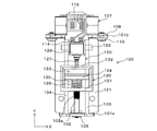
- First embodiment (outline) 1 is a perspective view of the driving device 100
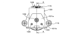
- FIG. 2 is a top view of the driving device 100
- FIG. 3 is a front view of the driving device 100
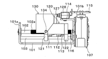
- FIG. 4 is a side sectional view of the driving device 100
- 5 is a side view of the driving device 100.
- the drive device 100 includes a slider 120 movable in a linear direction (Y-axis direction), a cover 130 connected to the slider 120, a front wall portion 131 that is a first portion of the cover 130, and a part of the slider 120.
- a coil spring 126 which is a coiled spring provided between the coil spring contact portion 124, a rear wall portion 132 which is a second portion of the cover 130, and a coil spring contact portion 124 which is a part of the slider 120.
- a holding portion 133 for holding the driven member is provided.
- the drive device 100 has a first state in which the driven member is not held by the holding portion 133 and a second state in which the driven member is held by the holding portion 133, and has the linear direction (Y-axis direction). ) Has a first length L1 in the first state and a second length L2 shorter than the first length L1 in the second state. Have.
- the relative position between the front wall portion 131 and the rear wall portion 132 of the cover 130 and the coil spring contact portion 124 of the slider 120 can be changed.
- the front wall portion 131 and the rear wall portion 132 of the cover 130 are movable with respect to the coil spring contact portion 124 of the slider 120 in a direction including at least the component in the linear direction (Y-axis direction).
- the cover 130 is connected to the slider 120 via a shaft 134. That is, the cover 130 is swingably supported by the slider 120 by the shaft 134, and when the cover 130 swings with respect to the slider 120, the cover 130 moves relative to the slider 120 in the drive axis direction (Y-axis direction). ) To move. More specifically, the movement of the cover 130 with respect to the slider 120 is rocking (minute rotation). However, considering this movement as a vector, the vector has components in the Y-axis direction and the Z-axis direction. Therefore, when the cover 130 swings about the shaft 134 with respect to the slider 120, the cover 130 also moves in the Z-axis direction at the same time, but also moves in the Y-axis direction.
- the direction of movement of the cover 130 with respect to the slider 120 may have at least a vector component in the Y-axis direction. That is, the direction in which the front wall portion 131 and the rear wall portion 132 can move with respect to the coil spring contact portion 124 may have at least a component in the Y-axis direction. Therefore, in addition to the configuration in which the cover 130 swings about the X axis to cause displacement in the Y axis direction with respect to the slider 120, the cover 130 linearly moves in the Y axis direction with respect to the slider 120. It is also possible to move to.
- the slider 120 is provided with a convex portion 125 that determines the position of the coil spring 126
- the cover 130 is provided with a concave portion 136 that determines the position of the coil spring 126.
- FIG. 1 shows a drive device 100.
- the drive device 100 linearly moves a driven member (not shown) in the Y-axis direction.
- the drive device 100 includes a base plate 101 that serves as a skeleton.
- the base plate 101 is fixed to a target to which the drive device 100 is fixed by a fastening member (screw or other known fastening means).
- the base plate 101 is made of a metal plate.
- the material of the base plate 101 is not particularly limited as long as it can be easily processed and its strength can be secured.
- the front and rear (both ends in the Y-axis direction) of the base plate 101 are bent upward (in the Z-axis direction), and a front frame 101a and a rear frame 101b that are integrated with the base plate 101 are formed.
- One end of a lead screw 102 which is a drive shaft, is rotatably held by a bearing 105 on the front frame 101a.
- the lead screw 102 is a cylindrical member having an external thread 102a formed on the outer circumference.
- the lead screw 102 penetrates the rear frame 101b in a freely rotatable state, and its tip is rotatably held by a bearing 106 in a motor frame 110 of a motor 107 described later.
- cylindrical guide members 103 and 104 are fixed to the front frame 101a and the rear frame 101b.
- the guide members 103 and 104 function as guides that restrict the movement of a slider 120, which will be described later, in the axial direction (Y-axis direction) of the drive shaft (lead screw 102).
- a motor 107 is fixed to the rear frame 101b.
- the motor 107 is a claw pole type PM stepping motor, but the type of the motor is not limited.
- the motor 107 is fixed to the plate 108, and the plate 108 is fixed to the rear frame 101b with screws 116.
- the lead screw 102 is fixed to the shaft center of the rotor 109 of the motor 107. With this structure, when the rotor 109 of the motor 107 rotates, the lead screw 102 rotates.
- the external threads 102a of the lead screw 102 are engaged with nuts 111 and 112 having internal threads formed therein so as to mesh with each other.
- the lead screw 102 and the nuts 111 and 112 mesh with each other in a state similar to a normal bolt-nut relationship.
- a slider 120 that moves in the axial direction of the drive shaft (Y-axis direction) together with the nuts 111 and 112 is engaged with the nuts 111 and 112.
- the slider 120 is made of resin and includes leg portions 121 and 122 that are separated from each other in the axial direction of the drive shaft (Y-axis direction).
- Each of the leg portions 121 and 122 includes a pair of guide holding portions that are separated from each other in the left-right direction (X-axis direction), and the guide members 103 and 104 penetrate the pair of guide holding portions in a slidable manner. ing.
- a recess 123 is formed inside the slider 120, and the nuts 111 and 112 are housed in the recess 123.
- the end surface of the nut 111 in the negative direction of the Y axis is in contact with the slider 120. Further, the end surface of the nut 112 opposite to the nut 111 indirectly contacts the inside of the slider 120 via the coil spring 113.
- the coil spring 113 is in a compressed state, and the biasing force of the coil spring 113 acts in a direction in which the nut 112 and the leg portion 122 are separated from each other.
- the nut 112 is not fixed to the slider 120, the nut 112 has a rectangular shape when viewed in the axial direction, and its upper surface is in contact with the slider 120 and cannot rotate with respect to the slider 120.
- the nut 111 also has the same shape as the nut 112, and its upper surface is in contact with the slider 120 and cannot rotate with respect to the slider 120.
- a resin cover 130 is held on the slider 120 by a shaft 134 so as to be rotatable about the shaft 134. That is, the cover 130 is supported (held) by the slider 120 in a state of swinging left and right with respect to the slider 120 with the shaft 134 as a fulcrum when viewed from the X-axis direction. Although the range of this swing is slight, this swing changes the relative position of the cover 130 on the Y axis with respect to the slider 120. That is, the cover 130 moves on the Y axis with respect to the slider 120, although not in parallel movement.
- a space 135 is formed inside the cover 130, and a coil spring contact portion 124 extending upward (Z-axis direction) from the slider 120 is located so as to divide the space 135 into two.
- the coil spring contact portion 124 is provided with a convex portion 125 that projects in the axial direction of the lead screw 102 that is the drive shaft, and the convex portion 125 is fitted inside the coil spring 126. By fitting the convex portion 125 into the coil spring 126, the position of the coil spring 126 with respect to the coil spring contact portion 124 (slider 120) is determined.
- the tip of the coil spring 126 is in contact with the inside of the front wall 131 of the cover 130. Further, a concave portion 136 is formed in a portion of the front wall portion 131 which comes into contact with the coil spring 126. By fitting the tip of the coil spring 126 into the recess 136, the position of the coil spring 126 with respect to the front wall portion 131 (cover 130) is determined.
- the cover 130 has a rear wall portion 132.
- the rear wall portion 132 is provided at a position apart from the front wall portion 131 in the axial direction of the lead screw 102.
- a gap between the rear wall portion 132 and the coil spring contact portion 124 of the slider 120 serves as a holding portion 133 that holds a driven member (not shown).
- the driven member is a plate-shaped semi-transmissive mirror that functions as a projection member of the head mounted display.
- the driven member is not limited to the semi-transmissive mirror.
- the slider 120 is provided with a columnar limit switch contact portion 127 protruding upward.
- the limit switch 128 is fixed to the limit switch mount 114 extending from the upper end of the rear frame 101b toward the cover 130.
- connection terminal board 115 The output terminal from the limit switch 128 and the drive signal terminal provided on the motor 107 are soldered to the connection terminal board 115.
- the gap between the coil spring contact portion 124 and the rear wall portion 132 (the gap of the holding portion 133 in the Y axis direction) is expanded. Force is applied in the direction in which the two are separated. As a result, the cover 130 slightly rotates about the shaft 134 in the clockwise direction in FIG. As a result, the front wall portion 131 and the coil spring contact portion 124 approach each other in the Y-axis direction, and the coil spring 126 is further compressed in the Y-axis direction.
- the compressed coil spring 126 generates a repulsive force that tends to separate the front wall portion 131 and the coil spring contact portion 124 from each other in the Y-axis direction, whereby the coil spring contact portion 124 and the rear wall portion 132 are separated from each other.
- the driven member is sandwiched between the coil spring contact portion 124 and the rear wall portion 132 due to the urging force that tends to narrow the coil. That is, the driven member is sandwiched between the coil spring contact portion 124 and the rear wall portion 132 by the repulsive force of the coil spring 126. This state is the second state.
- the coil spring contact portion 124 approaches the front wall portion 131 inside the cover 130, and the coil spring 126 is compressed in the Y axis direction. Due to this compression, a repulsive force of the coil spring 126 is generated, and a biasing force for separating the cover 130 from the slider 120 is generated. At this time, a biasing force that pushes the rear wall portion 132 against the coil spring contact portion 124 is generated, and the driven member is sandwiched by the holding portion 133.
- the force for sandwiching the driven member between the coil spring contact portion 124 and the rear wall portion 132 is derived from the repulsive force of the compressed coil spring 126 and is proportional to the repulsive force of the coil spring 126.
- the length L2 of the coil spring 126 in the Y-axis direction (driving direction) in the second state is L1> L2.
- the nuts 111 and 112 move in the negative Y-axis direction (left direction in FIG. 4) with respect to the lead screw 102.
- the slider 120 moves in the Y-axis negative direction. It is pushed by the nut 111 and moves in the negative Y-axis direction together with the nut 111.
- the nuts 111 and 112 move in the Y-axis positive direction with respect to the lead screw 102.
- the slider 120 is pushed in the Y axis positive direction by the nut 112 via the coil spring 113, and moves in the Y axis positive direction.
- the slider 120 moves linearly on the Y axis.
- the driven member held by the slider 120 also linearly moves on the Y axis together with the slider 120.
- the coil spring 113 exerts an urging force that pushes the slider 120 in the positive direction of the Y axis with the nut 112 as a fulcrum.
- This biasing force suppresses the backlash of the holding state of the slider 120 with respect to the lead screw 102, and secures the accuracy of movement control of the slider 120 in the axial direction by the rotation of the lead screw 102.
- the nut 111 may be lightly press-fitted, tightly fitted, or fixed to the slider 120 by other known fixing means.
- fixing one of the two nuts to the slider 120 the contact area between the nut on the fixing side and the slider 120 increases, and play between the slider 120 and the lead screw 102 is suppressed.
- the coil spring 113 between the nut 112 and the slider 120, the play between the nut 112 and the slider 120 is suppressed.
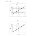
- FIG. 6 shows measured data of the compression coil spring.
- FIG. 6A shows the characteristics of the first coil spring.
- FIG. 6B shows the characteristics of the second coil spring.
- the two coil springs have different wire rods, and (B) is designed to generate a stronger repulsive force.
- 7C to 7E show characteristics of leaf springs for comparison.
- the coil spring and the leaf spring to be measured have dimensions and designs that can be mounted on the drive device of the prototype having the structure of FIG. Note that t is the thickness of the leaf spring.
- each graph shown in FIGS. 6 and 7 is the displacement length of the spring from the unloaded state.
- the vertical axis represents the repulsive force generated by the spring.
- the repulsive force at the same displacement length is relatively large for the coil spring and relatively small for the leaf spring.
- the thickness of the driven member in this embodiment is about 1.4 mm, and the displacement length of the spring at that time is also about the same.
- an appropriate force for sandwiching the driven member is about 8N to 12N.
- the appropriate range of the numerical value indicating the force sandwiching the driven member is larger than the above range when the driven member is larger, and is smaller than the above range when the driven member is small.
- FIG. 6 (A) shows a case where a repulsive force of about 8 N is obtained with a compression of 1.4 mm
- FIG. 6 (B) shows a repulsive force of about 11 N or less with a compression of 1.4 mm. The case is shown.
- the repulsive force is insufficient and it is difficult to respond.
- the problem of repulsive force may be overcome by using a thicker leaf spring, but this causes a problem that the force applied to the portion supporting the leaf spring becomes excessive.
- the plate spring having a high repulsive force has a narrow deformable range and cannot cope with the size of the driven member.
- both ends of the leaf spring are fixed inside the side surface of the cover 130, and the center (belly) of the leaf spring is brought into contact with the coil spring contact portion 124.
- the required repulsive force may be obtained by increasing the plate thickness of the leaf spring.
- the leaf spring is supported at both ends, a large load is applied to a locally narrow portion of the cover 130, and the problem of deformation and damage of the resin cover 130 becomes apparent. Also associated with this is reduced reliability in long term use.
- the coil spring has a larger stroke (displacement width) when elastically deformed than the leaf spring.
- the displacement of the cover 130 with respect to the coil spring contact portion 124 may increase when the driven member is mounted. In such a case, the stroke cannot be secured with the leaf spring, and it cannot be dealt with, but the coil spring can deal with it.
- the coil spring 126 can secure a large contact area with the front wall portion 131 (cover 130), and even if the repulsive force of the spring is set to be large, the load applied to the members forming the front wall portion 131 is small, and the cover 130. Deformation and damage are suppressed.
- the drive device 100 drives the slider 120 in the axial direction using a screw mechanism
- the present invention can be applied to a mechanism that linearly moves the slider by driving a cylinder or various linear actuators.
- the cover 130 swings with respect to the slider 120 about the shaft 134 as a fulcrum, so that the cover 130 moves in the axial direction (Y-axis direction) with respect to the slider 120, thereby causing a coil spring.
- the size of the gap between the contact part 124 and the rear wall part 132 (the size of the holding part 133 in the Y-axis direction) changes, the cover 130 is in the axial direction (Y-axis direction) with respect to the slider 120. It is also possible to make a parallel translation with the above. In this case, a structure is adopted in which the cover 130 is axially movable along a groove or rail provided on the slider 120 side or a guide having a known structure.
- a compressed coil spring may be arranged between the nuts 111 and 112. Further, in the structure of FIG. 4, the coil spring 113 may not be arranged, but a compressed coil spring may be arranged between the nuts 111 and 112. With these structures, the occurrence of play between the nut 111, the slider 120, and the lead screw 102 is suppressed. :
- the number of nuts can be 3 or more.
- at least one nut is fixed to the slider. That is, it is possible to adopt a structure in which at least two nuts are engaged (screw-engaged) with the lead screw and at least one of the two nuts is fixed to the slider. Further, in this structure, (1) a structure in which a compressed coil spring is arranged between two nuts adjacent in the axial direction, and (2) a structure in which a compressed coil spring is arranged between at least one of the nuts and the slider are It is possible.
- the structures (1) and (2) are also possible, and the structure (1) or (2) is also possible.
- the base plate 101 may be provided with a groove, rail, or other guide portion having a known structure, and the slider 120 may move along the guide portion. Further, the number of guide members or guide portions that regulate the movement of the slider 120 may be one, or may be three or more.
- a structure such as the convex portion 125 may be used instead of the concave portion 136 that determines the position of the coil spring 126 with respect to the front wall portion 131 (cover 130). Further, a structure in which the edge of the end portion of the coil spring 126 is pressed from inside or outside by a plurality of protrusions is also possible. Further, a structure in which a concave portion is provided as a positioning portion (guide portion) in a portion of the coil spring contact portion 124 where the coil spring 126 abuts, or a structure in which a plurality of protrusions press the edge of the end portion of the coil spring 126 from inside or outside is also possible. is there. Further, a structure for positioning the coil spring 126 may be provided on either the slider 120 or the cover 130.
- Spacers may be provided between the coil spring 126 and the coil spring contact portion 124 (slider 120) and between the coil spring 126 and the front wall portion 131 (cover 130) or both.
- the contact between the coil spring 126 and the coil spring contact portion 124 and the contact between the coil spring 126 and the front wall portion 131 are indirect contact via the spacer.
- FIG. 8 shows a top view of this embodiment.
- the positions of the coil spring 126 and the holding portion 133 are replaced with those in the case of the first embodiment of FIG. It is to be noted that the components other than the coil spring 126 and the holding portion 133 are the same as those in the first embodiment. Further, the holding structure of the coil spring 126 using a convex portion, a concave portion, and other known holding means is the same as that of the first embodiment.
- the coil spring 126 is arranged between the rear wall portion 132 which is the first portion of the cover 130 and the coil spring contact portion 124 which is a part of the slider 120.
- a holding portion 133 that holds the driven member is provided between the front wall portion 131 that is the second portion of the cover 130 and the coil spring contact portion 124 that is a part of the slider 120. The driven member is also sandwiched and held by this holding portion 133.
- the “first portion” of the cover 130 is the portion indicated by reference numeral 131, and the “second portion” is the portion indicated by reference numeral 132.
- the “first portion” of the cover 130 is the portion denoted by reference numeral 132 and the “second portion” is the portion denoted by reference numeral 131.
- the driven member can be strongly held by using the coil spring 126. Further, since the driven member is elastically sandwiched and held by the repulsive force of the coil spring 126, it is easy to assemble the driven member to the holding portion 133 and remove the driven member from the holding portion 133. Further, the coil spring 126 can secure a large contact area with the rear wall portion 132 (cover 130), and even if the repulsive force of the spring is set to be large, the load applied to the member forming the rear wall portion 132 is small, and the cover 130. Deformation and damage are suppressed.
Landscapes
- Engineering & Computer Science (AREA)
- General Engineering & Computer Science (AREA)
- Mechanical Engineering (AREA)
- Power Engineering (AREA)
- Transmission Devices (AREA)
- Connection Of Plates (AREA)
- Connection Of Motors, Electrical Generators, Mechanical Devices, And The Like (AREA)
Abstract
直線方向に被駆動部材を駆動する駆動装置における被駆動部材の保持を接着や締結によらず高い強度で行う技術を得る。駆動軸の延在方向である直線方向(Y軸方向)に移動可能なスライダ(120)と、スライダ(120)に連結され、スライダ(120)に対して前記直線方向に移動可能なカバー(130)と、被駆動部材をスライダ(120)とカバー(130)の間に挟んで保持する保持部(133)と、スライダ(120)とカバー(130)との間に被駆動部材を挟み込む力を発揮するコイルばね(126)とを備える駆動装置(100)。
Description
本発明は、被駆動部材を直線方向に移動させる駆動装置に関する。
モータの回転力を直線運動に変換し、被駆動部材を直線方向に移動させる駆動装置が知られている(例えば、特許文献1を参照)。
特許文献1に記載されたような駆動装置では、被駆動部材の保持強度が重要となる。また、製造コストや被駆動部材の交換の容易性といった点も重要となる。被駆動部材を保持する構造について、特許文献1には特に記載されていない。
例えば、接着やねじ止めにより被駆動部材を駆動装置に固定する方法が考えられるが、これらの方法は、作業性が悪く製造コストが上昇する。また、被駆動部材の交換が簡単に行えない。このような背景において、本発明は、直線方向に被駆動部材を駆動する駆動装置における被駆動部材の保持を接着や締結によらず高い強度で行う技術を得ることを発明の目的とする。
本発明は、直線方向に移動可能なスライダと、前記スライダに連結されたカバーと、前記カバーの第1の部分と前記スライダの一部との間に設けられたコイル状ばねと、前記カバーの第2の部分と前記スライダの前記一部との間に、被駆動部材を保持する保持部を備える駆動装置である。
本発明において、前記被駆動部材が前記保持部に保持されていない第1の状態と、前記被駆動部材が前記保持部に保持される第2の状態とを有し、前記直線方向における前記コイル状ばねの長さは、前記第1の状態においては第1の長さを有し、前記第2の状態においては前記第1の長さよりも短い第2の長さを有している態様が挙げられる。
本発明において、前記カバーの前記第1の部分及び前記第2の部分と、前記スライダの前記一部との間の相対位置が変化可能である態様が挙げられる。本発明において、前記カバーの前記第1の部分及び前記第2の部分は、前記スライダの前記一部に対して少なくとも前記直線方向の成分を含む方向に移動する態様が挙げられる。
本発明において、前記カバーは、前記スライダに軸により揺動可能に支持されており、前記カバーが前記スライダに対して揺動することで、前記カバーは前記スライダに対して少なくとも前記直線方向の成分を含む方向に移動する態様が挙げられる。
本発明において、前記スライダおよび前記カバーの少なくとも一方には、前記コイル状ばねの位置を決める凸部または凹部が設けられた態様が挙げられる。本発明において、前記コイル状ばねの付勢力が8N~12Nの範囲に含まれる値である態様が挙げられる。
本発明によれば、直線方向に被駆動部材を駆動する駆動装置における被駆動部材の保持を接着や締結によらず高い強度で行う技術が得られる。
1.第1の実施形態
(概要)
図1は駆動装置100の斜視図であり、図2は駆動装置100の上面図であり、図3は駆動装置100の前面図であり、図4は駆動装置100の側断面図であり、図5は駆動装置100の側面図である。
(概要)
図1は駆動装置100の斜視図であり、図2は駆動装置100の上面図であり、図3は駆動装置100の前面図であり、図4は駆動装置100の側断面図であり、図5は駆動装置100の側面図である。
駆動装置100は、直線方向(Y軸方向)に移動可能なスライダ120と、スライダ120に連結されたカバー130と、カバー130の第1の部分である前壁部131とスライダ120の一部であるコイルばね接触部124との間に設けられたコイル状ばねであるコイルばね126と、カバー130の第2の部分である後壁部132とスライダ120の一部であるコイルばね接触部124との間に、被駆動部材を保持する保持部133を備えている。
駆動装置100は、被駆動部材が保持部133に保持されていない第1の状態と、被駆動部材が保持部133に保持される第2の状態とを有し、前記直線方向(Y軸方向)におけるコイルばね126の長さは、前記第1の状態においては第1の長さL1を有し、前記第2の状態においては前記第1の長さL1よりも短い第2の長さL2を有する。
カバー130の前壁部131及び後壁部132と、スライダ120のコイルばね接触部124との間の相対位置は変化可能である。また、カバー130の前壁部131及び後壁部132は、スライダ120のコイルばね接触部124に対して少なくとも前記直線方向(Y軸方向)の成分を含む方向に移動可能である。
カバー130は、スライダ120に軸134を介して連結されている。すなわち、カバー130は、スライダ120に軸134により揺動可能に支持されており、カバー130がスライダ120に対して揺動することで、カバー130はスライダ120に対して駆動軸方向(Y軸方向)に移動する。より詳細にいうと、スライダ120に対するカバー130の移動は揺動(微小回転)である。しかしながら、この移動をベクトルで考えると、当該ベクトルはY軸方向とZ軸方向の成分を有している。よって、スライダ120に対するカバー130の軸134を中心とする揺動では、同時にZ軸方向への移動も生じるが、Y軸方向への移動も生じる。
スライダ120に対するカバー130の移動の方向は、少なくともY軸方向のベクトル成分を有していればよい。すなわち、コイルばね接触部124に対して前壁部131および後壁部132が動くことができる方向は、少なくともY軸方向の成分を有していればよい。よって、上記のカバー130がX軸を軸として揺動することで、スライダ120に対してY軸方向への変位が生じる形態の他に、スライダ120に対してカバー130がY軸方向に直線的に移動する形態も可能である。
また、スライダ120には、コイルばね126の位置を決める凸部125が設けられ、カバー130には、コイルばね126の位置を決める凹部136が設けられている。
(構成)
図1には、駆動装置100が示されている。駆動装置100は、図示しない被駆動部材をY軸方向に直線移動させる。駆動装置100は、骨格となる土台プレート101を備えている。土台プレート101が駆動装置100を固定する対象に締結部材(ネジ、その他公知の締結手段)により固定される。土台プレート101は、金属板により構成されている。土台プレート101の材質は、加工が行い易く、また強度が確保できるのであれば特に限定されない。
図1には、駆動装置100が示されている。駆動装置100は、図示しない被駆動部材をY軸方向に直線移動させる。駆動装置100は、骨格となる土台プレート101を備えている。土台プレート101が駆動装置100を固定する対象に締結部材(ネジ、その他公知の締結手段)により固定される。土台プレート101は、金属板により構成されている。土台プレート101の材質は、加工が行い易く、また強度が確保できるのであれば特に限定されない。
土台プレート101の前後(Y軸方向における両端)は、上方(Z軸方向)に折れ曲がった構造とされ、土台プレート101と一体となった前フレーム101aと後フレーム101bが形成されている。前フレーム101aには、駆動軸であるリードスクリュー102の一端が軸受105により回転自在な状態で保持されている。リードスクリュー102は、外周に雄ねじ102aが形成された円柱状の部材である。リードスクリュー102は、後フレーム101bを回転自在な状態で貫通し、その先端は後述するモータ107のモータフレーム110に軸受106により回転自在な状態で保持されている。
また、前フレーム101aと後フレーム101bには、円柱状のガイド部材103,104が固定されている。ガイド部材103,104は、後述するスライダ120の動きを駆動軸(リードスクリュー102)の軸方向(Y軸方向)に規制するガイドして機能する。
後フレーム101bには、モータ107が固定されている。モータ107は、クローポール型PMステッピングモータであるが、モータの形式は限定されない。モータ107は、プレート108に固定され、プレート108が後フレーム101bにネジ116により固定されている。モータ107のロータ109の軸中心には、リードスクリュー102が固定されている。この構造により、モータ107のロータ109が回転すると、リードスクリュー102が回転する。
リードスクリュー102の雄ねじ102aの部分には、内側に雌ネジが形成されたナット111,112が噛み合った状態で結合されている。リードスクリュー102とナット111,112は、通常のボルトとナットの関係と同様な状態で噛合っている。
ナット111,112には、ナット111,112と共に駆動軸の軸方向(Y軸方向)で移動するスライダ120が係合している。スライダ120は、樹脂製であり、駆動軸の軸方向(Y軸方向)で離間した脚部121,122を備えている。脚部121,122のそれぞれは、左右方向(X軸方向)に離間した一対のガイド保持部を備え、この一対のガイド保持部のそれぞれにガイド部材103と104が摺動可能な状態で貫通している。
スライダ120の内側には、窪み123が形成され、窪み123にナット111,112が納められている。ナット111のY軸負の方向の端面は、スライダ120に接触している。また、ナット112のナット111と反対側の端面がコイルばね113を介してスライダ120の内側に間接的に接触している。コイルばね113は圧縮状態とされ、ナット112と脚部122とが離れる方向にコイルばね113による付勢力が働いている。
ナット112は、スライダ120に固定されていないが、ナット112は軸方向から見て矩形であり、その上面がスライダ120に接触し、スライダ120に対して回転できない状態とされている。ナット111もナット112と同じ形状であり、その上面がスライダ120に接触し、スライダ120に対して回転できない状態とされている。
スライダ120には、樹脂製のカバー130が軸134により当該軸134を中心に回転が自在な状態で保持されている。つまり、カバー130は、スライダ120に対して、X軸方向から見て、軸134を支点として左右に揺動する状態でスライダ120に支持(保持)されている。この揺動の範囲は、僅かであるが、この揺動により、スライダ120に対するカバー130のY軸上における相対位置が変化する。つまり、平行移動ではないが、スライダ120に対してカバー130がY軸上で移動する。カバー130の内側には空間135が形成され、空間135を2分するように、スライダ120から上方(Z軸方向)に延在したコイルばね接触部124が位置している。
コイルばね接触部124には、駆動軸であるリードスクリュー102の軸方向に突出する凸部125が設けられ、凸部125は、コイルばね126の内側に嵌め込まれている。凸部125をコイルばね126に嵌め込むことで、コイルばね接触部124(スライダ120)に対するコイルばね126の位置が決められる。
コイルばね126の先端はカバー130の前壁部131の内側に接触している。また、前壁部131のコイルばね126が接触する部分には凹部136が形成されている。凹部136にコイルばね126の先端が嵌め込まれることで、前壁部131(カバー130)に対するコイルばね126の位置が決められる。
また、カバー130は後壁部132を有している。後壁部132は、前壁部131に対してリードスクリュー102の軸方向上で離れた位置に設けられている。後壁部132と、スライダ120のコイルばね接触部124との間の隙間が被駆動部材(図示せず)を保持する保持部133となる。この例において、被駆動部材は、ヘッドマウントディスプレイの投影部材として機能する板状の半透過ミラーである。もちろん、被駆動部材は半透過ミラーに限定されない。
スライダ120は、上方向に突出する柱状のリミットスイッチ接触部127を備えている。リミットスイッチ接触部127がリミットスイッチ128に接触することで、スライダ120の駆動軸上(リードスクリューの軸上)における基準位置が電気的に検出される。リミットスイッチ128は、後フレーム101bの上端からカバー130の方向に延在したリミットスイッチ取付台114に固定されている。
リミットスイッチ128からの出力端子とモータ107に設けられた駆動信号端子が接続端子基板115に半田接続されている。接続端子基板115に外部からのモータ駆動信号とリミットスイッチ128からの検出信号を伝送するコネクタが接続される。
(被駆動部材を保持する仕組み)
保持部133に図示しない被駆動部材が保持されていない状態(第1の状態)において、保持部133のY軸方向の隙間寸法は、被駆動部材のY軸方向の寸法よりも小さい。また、この状態において、コイルばね126は圧縮されており、この圧縮により発生する反発力により、図4,5の視点から見て、カバー130は反時計回り方向に付勢されている。
保持部133に図示しない被駆動部材が保持されていない状態(第1の状態)において、保持部133のY軸方向の隙間寸法は、被駆動部材のY軸方向の寸法よりも小さい。また、この状態において、コイルばね126は圧縮されており、この圧縮により発生する反発力により、図4,5の視点から見て、カバー130は反時計回り方向に付勢されている。
保持部133に被駆動部材が上方(Z軸正の方向)から押し込まれると、コイルばね接触部124と後壁部132との間の隙間(保持部133のY軸方向の隙間)が押し拡げられ、両者が離れる方向に力が働く。この結果、カバー130は、軸134を中心に図4における時計回り方向に僅かに回転する。この結果、前壁部131とコイルばね接触部124とがY軸方向で近づき、コイルばね126がY軸方向で更に圧縮される。圧縮されたコイルばね126は、前壁部131とコイルばね接触部124とをY軸方向で離そうとする反発力を発生し、それにより、コイルばね接触部124と後壁部132との間を狭めようとする付勢力が生じ、コイルばね接触部124と後壁部132との間に被駆動部材が挟まれる。つまり、コイルばね126の反発力により、コイルばね接触部124と後壁部132との間に被駆動部材が挟まれる。この状態が第2の状態となる。
すなわち、保持部133に被駆動部材が押し込まれることで、カバー130の内側でコイルばね接触部124が前壁部131に近づき、コイルばね126がY軸方向で圧縮される。この圧縮により、コイルばね126の反発力が生じ、カバー130をスライダ120から離そうとする付勢力が発生する。この際、コイルばね接触部124に後壁部132を押し付けようとする付勢力が生じ、保持部133に被駆動部材が挟まれる。コイルばね接触部124と後壁部132の間で被駆動部材を挟む込み力は、圧縮されたコイルばね126の反発力に由来し、コイルばね126の反発力に比例したものとなる。
ここで、図示しない被駆動部材が保持部133に保持されていない第1の状態におけるY軸方向(駆動方向)におけるコイルばね126の長さL1と、図示しない被駆動部材が保持部133に保持されている第2の状態におけるY軸方向(駆動方向)におけるコイルばね126の長さL2には、L1>L2の関係がある。
(動作)
モータ107に駆動信号を供給し、モータ107を回転させると、リードスクリュー102が回転する。ナット111,112は、スライダ120に対して回転できないので、リードスクリュー102が回転すると、ねじの作用により、リードスクリュー102に対してナット111,112を軸方向(Y軸方向)に動かそうとする駆動力が発生する。この結果、ナット111,112は、リードスクリュー102の軸の延在方向に沿って、リードスクリュー102に対して相対的に移動する。
モータ107に駆動信号を供給し、モータ107を回転させると、リードスクリュー102が回転する。ナット111,112は、スライダ120に対して回転できないので、リードスクリュー102が回転すると、ねじの作用により、リードスクリュー102に対してナット111,112を軸方向(Y軸方向)に動かそうとする駆動力が発生する。この結果、ナット111,112は、リードスクリュー102の軸の延在方向に沿って、リードスクリュー102に対して相対的に移動する。
例えば、リードスクリュー102が回転することで、ナット111,112がリードスクリュー102に対して、Y軸負の方向(図4の左の方向)に動くとする。この場合、ナット111のY軸負の方向の端面がスライダ120に接触し、ナット111はスライダ120に対してY軸負の方向に動けないので、スライダ120は、Y軸負の方向に移動しようとするナット111に押され、ナット111と一緒にY軸負の方向に動く。
また、上記の場合と逆の方向にリードスクリュー102が回転すると、ナット111,112がリードスクリュー102に対して、Y軸正の方向に動く。この際、スライダ120は、コイルばね113を介してナット112によってY軸正の方向に押され、Y軸正の方向に動く。
すなわち、モータ107を回転させることで、スライダ120がY軸上を直線移動する。この際、スライダ120に保持された被駆動部材もスライダ120と共にY軸上を直線移動する。
上記のスライダ120の移動の際、ナット112を支点として、コイルばね113によりスライダ120をY軸正の方向に押す付勢力が働いている。この付勢力により、リードスクリュー102に対するスライダ120の保持状態のガタが抑えられ、リードスクリュー102の回転によるスライダ120の軸方向での移動制御の精度が確保されている。
ナット111を軽圧入、しばり嵌め、その他公知の固定手段によってスライダ120に固定してもよい。2つあるナットの一方をスライダ120に固定することで、固定する側のナットとスライダ120の接触面積が増えてスライダ120とリードスクリュー102の間のガタが抑制される。また、ナット112とスライダ120との間にコイルばね113を配置することで、ナット112とスライダ120の間のガタが抑制される。
(実測値)
図6に圧縮コイルばねの実測データを示す。図6(A)は、第1のコイルばねの特性である。図6(B)は、第2のコイルばねの特性である。2つのコイルばねは、構成する線材に違いがあり、(B)の方が強い反発力を生じる仕様とされている。図7(C)~(E)は、比較のための板ばねの特性である。ここで、測定対象のコイルばねと板ばねは、図1の構造を有する試作品の駆動装置に装着可能な寸法およびデザインとした。なお、tは板ばねの厚みである。
図6に圧縮コイルばねの実測データを示す。図6(A)は、第1のコイルばねの特性である。図6(B)は、第2のコイルばねの特性である。2つのコイルばねは、構成する線材に違いがあり、(B)の方が強い反発力を生じる仕様とされている。図7(C)~(E)は、比較のための板ばねの特性である。ここで、測定対象のコイルばねと板ばねは、図1の構造を有する試作品の駆動装置に装着可能な寸法およびデザインとした。なお、tは板ばねの厚みである。
図6および図7に示す各グラフの横軸は、無負荷状態からのばねの変位長である。縦軸は、当該ばねが発生する反発力である。図6および図7のグラフから判るように、同じ変位長における反発力がコイルばねは相対的に大きく、板ばねは相対的に小さい。
本実施の形態における被駆動部材の厚み寸法は1.4mm程度であり、その際のばねの変位長も同程度となる。そして、被駆動部材を挟む力は、8N~12N程度が適切であることが実験により判明している。この、被駆動部材を挟む力を示す数値の適切な範囲は、被駆動部材が大きくなれば上記の範囲より大きくなり、被駆動部材が小さければ上記の範囲より小さくなる。図6(A)には、1.4mmの圧縮で約8Nの反発力が得られる場合が示され、図6(B)には、1.4mmの圧縮で約11N弱の反発力が得られる場合が示されている。
上記の要求に対して、図7(A)~(C)に示す板ばねのサンプルでは、反発力が足りず、対応が困難である。より厚みのある板ばねを用いることで、反発力の問題は克服できる可能性があるが、そうすると、板ばねを支える部分に加わる力が過大となる問題が発生する。また、高反発力の板ばねは、変形可能な範囲が狭く、被駆動部材の厚みの大小に対応できない。
すなわち、仮に、コイルばね126の代わりに板ばねを利用した場合、板ばねの両端をカバー130の側面内側に固定し、板ばねの中央(腹)の部分をコイルばね接触部124に接触させる構造となる。この場合、上述した実験データから示唆されるように、板ばねの板厚を大きくすれば要求される反発力が得られる可能性はある。しかしながら、板ばねは両端で支えるので、カバー130の局所的な狭い部分に大きな負荷が加わり、樹脂製のカバー130の変形や破損の問題が顕在化する。また、これに関連して、長期使用における信頼性が低下する。
この点、コイルばね126を採用した場合は、大きな反発力が得られる。また、カバー130への接触面積を大きく確保できるので、カバー130に加わる負担を低減できる。
また、板バネに比較してコイルばねは、弾性変形時のストローク(変位幅)を大きくとれる。被駆動部材によっては、被駆動部材の装着時にコイルばね接触部124に対するカバー130の変位が大きくなる場合が有り得る。このような場合、板ばねではストロークが確保できず対応できないが、コイルばねであれば対応できる。
(優位性)
コイルばね126の反発力を利用してコイルばね接触部124と後壁部132との間に被駆動部材を挟むことで、被駆動部材を強く保持できる。また、被駆動部材はコイルばね126の反発力により弾性的に挟まれて保持されるので、保持部133への被駆動部材の組み付けや保持部133からの被駆動部材の取り外しも容易である。
コイルばね126の反発力を利用してコイルばね接触部124と後壁部132との間に被駆動部材を挟むことで、被駆動部材を強く保持できる。また、被駆動部材はコイルばね126の反発力により弾性的に挟まれて保持されるので、保持部133への被駆動部材の組み付けや保持部133からの被駆動部材の取り外しも容易である。
また、コイルばね126は、前壁部131(カバー130)への接触面積を大きく確保でき、ばねの反発力を大きく設定しても前壁部131を構成する部材に加わる負担が小さく、カバー130の変形や破損が抑制される。
(その他)
駆動装置100は、ねじ機構を用いてスライダ120の軸方向における駆動を行っているが、シリンダや各種のリニアアクチュエータの駆動によってスライダを直線運動させる機構にも本発明を適用することができる。
駆動装置100は、ねじ機構を用いてスライダ120の軸方向における駆動を行っているが、シリンダや各種のリニアアクチュエータの駆動によってスライダを直線運動させる機構にも本発明を適用することができる。
また、駆動装置100では、スライダ120に対して、カバー130が軸134を支点として揺動することで、スライダ120に対してカバー130が軸方向(Y軸の方向)に動き、それによりコイルばね接触部124と後壁部132との間の隙間の寸法(保持部133のY軸方向の寸法)が変化する構造であるが、スライダ120に対して、カバー130が軸方向(Y軸方向)に平行移動する形態も可能である。この場合、スライダ120の側に設けられた溝やレール、その他公知の構造を有するガイドに沿ってカバー130が軸方向で移動可能な構造が採用される。
図4の構造において、ナット111と112の間に圧縮したコイルばねを配置してもよい。また、図4の構造において、コイルばね113を配置せず、ナット111と112の間に圧縮したコイルばねを配置してもよい。これらの構造によれば、ナット111とスライダ120およびリードスクリュー102間のガタの発生が抑制される。
図4の構造において、ナット111をスライダ120に固定せず、ナット112をスライダ120に固定し、両ナット間に圧縮したコイルばねを配置した構造も可能である。また、この構造において、コイルばね113を配置せず、ナット111と112の間に圧縮したコイルばねを配置する構造も可能である。これらの構造によれば、スライダ120とリードスクリュー102との間のガタの発生を抑えることができる。
また、ナットの数を3個以上とすることもできる。この場合、少なくとも一つのナットをスライダに固定する。すなわち、リードスクリューに少なくとも2つのナットを噛み合わせ(螺合させ)、2つのナットの少なくとも一方をスライダに固定した構造が可能である。また、この構造において、(1)軸方向で隣接する2つのナットの間に圧縮したコイルばねを配置した構造、(2)少なくとも一方のナットとスライダの間に圧縮したコイルばねを配置した構造が可能である。ここで、(1)および(2)の構造も可能であり、(1)または(2)の構造も可能である。
ガイド部材103,104の代わりに、土台プレート101に溝やレール、その他公知の構造を有するガイド部を設け、それに沿ってスライダ120が動くようにしてもよい。また、スライダ120の動きを規制するガイド部材やガイド部は、1つでもよく、あるいは3つ以上であってもよい。
前壁部131(カバー130)に対するコイルばね126の位置を決める凹部136の代わりに、凸部125のような構造を用いてもよい。また、複数の突起でコイルばね126の端部の縁を内側または外側から押える構造も可能である。また、コイルばね接触部124のコイルばね126が当たる部分に凹部を位置決め部(ガイド部)として設ける構造、あるいは複数の突起でコイルばね126の端部の縁を内側または外側から押える構造も可能である。また、コイルばね126の位置決めを行う構造をスライダ120とカバー130のいずれか一方に設ける構造も可能である。
コイルばね126とコイルばね接触部124(スライダ120)との間、およびコイルばね126と前壁部131(カバー130)との間の一方または両方にスペーサを入れてもよい。この場合、コイルばね126とコイルばね接触部124との間の接触、およびコイルばね126と前壁部131との間の接触は、スペーサを介した間接的な接触となる。
2.第2の実施形態
図8に本実施形態の上面図を示す。この例では、コイルばね126と保持部133の位置が、図2の第1の実施形態の場合と入れ替わっている。なお、コイルばね126と保持部133以外については、第1の実施形態と同じである。また、凸部や凹部、その他公知の保持手段を用いたコイルばね126の保持構造は、第1の実施形態の場合と同じである。
図8に本実施形態の上面図を示す。この例では、コイルばね126と保持部133の位置が、図2の第1の実施形態の場合と入れ替わっている。なお、コイルばね126と保持部133以外については、第1の実施形態と同じである。また、凸部や凹部、その他公知の保持手段を用いたコイルばね126の保持構造は、第1の実施形態の場合と同じである。
この例では、コイルばね126は、カバー130の第1の部分となる後壁部132とスライダ120の一部であるコイルばね接触部124との間に配置されている。また、カバー130の第2の部分となる前壁部131とスライダ120の一部であるコイルばね接触部124との間が被駆動部材を保持する保持部133となっている。この保持部133も部分に被駆動部材が挟まれて保持される。
図2の第1の実施形態では、カバー130の「第1の部分」が符号131の部分であり、「第2の部分」が符号132の部分となる。他方で、図8の第2の実施形態では、カバー130の「第1の部分」が符号132の部分であり、「第2の部分」が符号131の部分となる。
第2の実施形態によっても、第1の実施形態と同様の効果が実現される。すなわち、コイルばね126を用いることで被駆動部材を強く保持できる。また、被駆動部材がコイルばね126の反発力により弾性的に挟まれて保持されるので、保持部133への被駆動部材の組み付けや保持部133からの被駆動部材の取り外しが容易となる。また、コイルばね126は、後壁部132(カバー130)への接触面積を大きく確保でき、ばねの反発力を大きく設定しても後壁部132を構成する部材に加わる負担が小さく、カバー130の変形や破損が抑制される。
100…駆動装置、101…土台プレート、101a…前フレーム、101b…後フレーム、102…リードスクリュー、103…ガイド部材、104…ガイド部材、105…軸受、106…軸受、107…モータ、108…プレート、109…ロータ、110…モータフレーム、111…ナット、112…ナット、113…コイルばね、114…リミットスイッチ取付台、120…スライダ、121…脚部、122…脚部、123…窪み、124…コイルばね接触部、125…凸部、126…コイルばね、127…リミットスイッチ接触部、128…リミットスイッチ、130…カバー、131…前壁部、132…後壁部、133…保持部、134…軸、135…空間、136…凹部。
Claims (7)
- 直線方向に移動可能なスライダと、
前記スライダに連結されたカバーと、
前記カバーの第1の部分と前記スライダの一部との間に設けられたコイル状ばねと、
前記カバーの第2の部分と前記スライダの前記一部との間に、被駆動部材を保持する保持部を備える駆動装置。 - 前記被駆動部材が前記保持部に保持されていない第1の状態と、前記被駆動部材が前記保持部に保持される第2の状態とを有し、前記直線方向における前記コイル状ばねの長さは、前記第1の状態においては第1の長さを有し、前記第2の状態においては前記第1の長さよりも短い第2の長さを有している請求項1に記載の駆動装置。
- 前記カバーの前記第1の部分及び前記第2の部分と、前記スライダの前記一部との間の相対位置が変化可能である請求項1または2のいずれか一項に記載の駆動装置。
- 前記カバーの前記第1の部分及び前記第2の部分は、前記スライダの前記一部に対して少なくとも前記直線方向の成分を含む方向に移動する請求項1乃至3のいずれか一項に記載の駆動装置。
- 前記カバーは、前記スライダに軸により揺動可能に支持されており、前記カバーが前記スライダに対して揺動することで、前記カバーは前記スライダに対して少なくとも前記直線方向の成分を含む方向に移動する請求項1乃至4のいずれか一項に記載の駆動装置。
- 前記スライダおよび前記カバーの少なくとも一方には、前記コイル状ばねの位置を決める凸部または凹部が設けられた請求項1乃至5のいずれか一項に記載の駆動装置。
- 前記コイル状ばねの付勢力が8N~12Nの範囲に含まれる値である請求項1乃至6のいずれか一項に記載の駆動装置。
Priority Applications (2)
| Application Number | Priority Date | Filing Date | Title |
|---|---|---|---|
| DE112019005847.9T DE112019005847T5 (de) | 2018-11-22 | 2019-11-15 | Antriebsvorrichtung |
| CN201980076527.3A CN113167364B (zh) | 2018-11-22 | 2019-11-15 | 驱动装置 |
Applications Claiming Priority (2)
| Application Number | Priority Date | Filing Date | Title |
|---|---|---|---|
| JP2018219157A JP7158258B2 (ja) | 2018-11-22 | 2018-11-22 | 駆動装置 |
| JP2018-219157 | 2018-11-22 |
Publications (1)
| Publication Number | Publication Date |
|---|---|
| WO2020105555A1 true WO2020105555A1 (ja) | 2020-05-28 |
Family
ID=70773426
Family Applications (1)
| Application Number | Title | Priority Date | Filing Date |
|---|---|---|---|
| PCT/JP2019/044865 Ceased WO2020105555A1 (ja) | 2018-11-22 | 2019-11-15 | 駆動装置 |
Country Status (4)
| Country | Link |
|---|---|
| JP (1) | JP7158258B2 (ja) |
| CN (1) | CN113167364B (ja) |
| DE (1) | DE112019005847T5 (ja) |
| WO (1) | WO2020105555A1 (ja) |
Families Citing this family (3)
| Publication number | Priority date | Publication date | Assignee | Title |
|---|---|---|---|---|
| US10129601B2 (en) * | 2014-08-25 | 2018-11-13 | Coherent Logix, Incorporated | Shared spectrum access for broadcast and bi-directional, packet-switched communications |
| JP7545853B2 (ja) | 2020-10-05 | 2024-09-05 | ミネベアミツミ株式会社 | ナットアッセンブリおよび駆動装置 |
| JP7610998B2 (ja) * | 2021-02-19 | 2025-01-09 | ニデックインスツルメンツ株式会社 | 直線駆動装置 |
Citations (3)
| Publication number | Priority date | Publication date | Assignee | Title |
|---|---|---|---|---|
| JPH08135655A (ja) * | 1994-09-16 | 1996-05-31 | Nippon Seiko Kk | 直動気体軸受の駆動装置 |
| JP2008175358A (ja) * | 2007-01-22 | 2008-07-31 | Mitsuba Corp | 電動アクチュエータ |
| WO2018084312A1 (ja) * | 2016-11-07 | 2018-05-11 | 日本電産サンキョー株式会社 | 直線駆動装置、モータ、および直線駆動装置の製造方法 |
Family Cites Families (5)
| Publication number | Priority date | Publication date | Assignee | Title |
|---|---|---|---|---|
| JP3670492B2 (ja) * | 1998-09-30 | 2005-07-13 | 京セラ株式会社 | 直線案内装置 |
| CN101191542B (zh) * | 2006-11-28 | 2010-05-12 | 湖北京山轻工机械股份有限公司 | 一种动力拖动装置 |
| JP6042483B2 (ja) * | 2015-04-27 | 2016-12-14 | 日本電産サンキョーシーエムアイ株式会社 | 直線駆動装置 |
| JP2017177880A (ja) * | 2016-03-28 | 2017-10-05 | 日本精機株式会社 | 表示装置 |
| JP6381847B1 (ja) * | 2018-05-22 | 2018-08-29 | 黒田精工株式会社 | 工作機械用送りねじ装置におけるナット支持装置、工作機械用送りねじ装置及び平面研削盤 |
-
2018
- 2018-11-22 JP JP2018219157A patent/JP7158258B2/ja active Active
-
2019
- 2019-11-15 WO PCT/JP2019/044865 patent/WO2020105555A1/ja not_active Ceased
- 2019-11-15 CN CN201980076527.3A patent/CN113167364B/zh active Active
- 2019-11-15 DE DE112019005847.9T patent/DE112019005847T5/de active Pending
Patent Citations (3)
| Publication number | Priority date | Publication date | Assignee | Title |
|---|---|---|---|---|
| JPH08135655A (ja) * | 1994-09-16 | 1996-05-31 | Nippon Seiko Kk | 直動気体軸受の駆動装置 |
| JP2008175358A (ja) * | 2007-01-22 | 2008-07-31 | Mitsuba Corp | 電動アクチュエータ |
| WO2018084312A1 (ja) * | 2016-11-07 | 2018-05-11 | 日本電産サンキョー株式会社 | 直線駆動装置、モータ、および直線駆動装置の製造方法 |
Also Published As
| Publication number | Publication date |
|---|---|
| JP7158258B2 (ja) | 2022-10-21 |
| JP2020085102A (ja) | 2020-06-04 |
| DE112019005847T5 (de) | 2021-10-21 |
| CN113167364A (zh) | 2021-07-23 |
| CN113167364B (zh) | 2024-11-22 |
Similar Documents
| Publication | Publication Date | Title |
|---|---|---|
| US11366333B2 (en) | Camera device having hand-shake correction function | |
| CN109923332B (zh) | 直线驱动装置、马达以及直线驱动装置的制造方法 | |
| JP7158258B2 (ja) | 駆動装置 | |
| US9247140B2 (en) | Vibration-type driving unit, two-dimensional driving apparatus, image-blur correction apparatus, interchangeable lens, image capturing apparatus, and automatic stage | |
| JP5047980B2 (ja) | レンズ駆動装置 | |
| WO2010101139A1 (ja) | 振動モータユニット、振動モータ及び振動モータを用いたレンズ駆動装置 | |
| JP4558071B2 (ja) | 駆動装置、およびこれを備えた撮像装置、電子機器 | |
| US7215489B2 (en) | Optical apparatus | |
| JP2007322709A (ja) | 光学部材支持機構、光学装置、および間隔調整部材 | |
| JP2007322709A5 (ja) | ||
| JP4211363B2 (ja) | レンズ駆動装置 | |
| JP2009150922A (ja) | アクチュエータ、撮像機器および携帯電子機器 | |
| JP6152019B2 (ja) | 超音波モータを用いたリニア駆動ユニット | |
| US7502553B2 (en) | Optical apparatus | |
| JPH10142472A (ja) | レンズ駆動機構 | |
| JP5584326B2 (ja) | 磁気駆動装置及び光量絞り装置及び光学機器 | |
| JP7545853B2 (ja) | ナットアッセンブリおよび駆動装置 | |
| JPH10123399A (ja) | レンズ駆動機構 | |
| JP2010206907A (ja) | 振動モータユニット | |
| JPH11231197A (ja) | レンズ駆動装置 | |
| US11367583B2 (en) | Seesaw type operation unit used for zooming operation in video camera and electronic device | |
| US20210184552A1 (en) | Electromagnetic Actuator And Vibration Application Mechanism Including The Same | |
| TWI773527B (zh) | 光學部件驅動裝置、照相機裝置以及電子設備 | |
| JP2013080080A (ja) | カム機構およびそれを利用したレンズ鏡筒 | |
| JPH10123405A (ja) | レンズ駆動機構 |
Legal Events
| Date | Code | Title | Description |
|---|---|---|---|
| 121 | Ep: the epo has been informed by wipo that ep was designated in this application |
Ref document number: 19886123 Country of ref document: EP Kind code of ref document: A1 |
|
| 122 | Ep: pct application non-entry in european phase |
Ref document number: 19886123 Country of ref document: EP Kind code of ref document: A1 |