WO2020105552A1 - クランプ方法及びクランプ装置 - Google Patents
クランプ方法及びクランプ装置Info
- Publication number
- WO2020105552A1 WO2020105552A1 PCT/JP2019/044839 JP2019044839W WO2020105552A1 WO 2020105552 A1 WO2020105552 A1 WO 2020105552A1 JP 2019044839 W JP2019044839 W JP 2019044839W WO 2020105552 A1 WO2020105552 A1 WO 2020105552A1
- Authority
- WO
- WIPO (PCT)
- Prior art keywords
- members
- support portion
- pressure
- hole
- work
- Prior art date
- Legal status (The legal status is an assumption and is not a legal conclusion. Google has not performed a legal analysis and makes no representation as to the accuracy of the status listed.)
- Ceased
Links
Images



Classifications
-
- B—PERFORMING OPERATIONS; TRANSPORTING
- B21—MECHANICAL METAL-WORKING WITHOUT ESSENTIALLY REMOVING MATERIAL; PUNCHING METAL
- B21J—FORGING; HAMMERING; PRESSING METAL; RIVETING; FORGE FURNACES
- B21J15/00—Riveting
- B21J15/02—Riveting procedures
-
- B—PERFORMING OPERATIONS; TRANSPORTING
- B21—MECHANICAL METAL-WORKING WITHOUT ESSENTIALLY REMOVING MATERIAL; PUNCHING METAL
- B21J—FORGING; HAMMERING; PRESSING METAL; RIVETING; FORGE FURNACES
- B21J15/00—Riveting
- B21J15/10—Riveting machines
- B21J15/14—Riveting machines specially adapted for riveting specific articles, e.g. brake lining machines
- B21J15/142—Aerospace structures
-
- B—PERFORMING OPERATIONS; TRANSPORTING
- B21—MECHANICAL METAL-WORKING WITHOUT ESSENTIALLY REMOVING MATERIAL; PUNCHING METAL
- B21J—FORGING; HAMMERING; PRESSING METAL; RIVETING; FORGE FURNACES
- B21J15/00—Riveting
- B21J15/10—Riveting machines
- B21J15/28—Control devices specially adapted to riveting machines not restricted to one of the preceding subgroups
-
- B—PERFORMING OPERATIONS; TRANSPORTING
- B21—MECHANICAL METAL-WORKING WITHOUT ESSENTIALLY REMOVING MATERIAL; PUNCHING METAL
- B21J—FORGING; HAMMERING; PRESSING METAL; RIVETING; FORGE FURNACES
- B21J15/00—Riveting
- B21J15/38—Accessories for use in connection with riveting, e.g. pliers for upsetting; Hand tools for riveting
- B21J15/42—Special clamping devices for workpieces to be riveted together, e.g. operating through the rivet holes
-
- B—PERFORMING OPERATIONS; TRANSPORTING
- B23—MACHINE TOOLS; METAL-WORKING NOT OTHERWISE PROVIDED FOR
- B23B—TURNING; BORING
- B23B35/00—Methods for boring or drilling, or for working essentially requiring the use of boring or drilling machines; Use of auxiliary equipment in connection with such methods
-
- B—PERFORMING OPERATIONS; TRANSPORTING
- B23—MACHINE TOOLS; METAL-WORKING NOT OTHERWISE PROVIDED FOR
- B23Q—DETAILS, COMPONENTS, OR ACCESSORIES FOR MACHINE TOOLS, e.g. ARRANGEMENTS FOR COPYING OR CONTROLLING; MACHINE TOOLS IN GENERAL CHARACTERISED BY THE CONSTRUCTION OF PARTICULAR DETAILS OR COMPONENTS; COMBINATIONS OR ASSOCIATIONS OF METAL-WORKING MACHINES, NOT DIRECTED TO A PARTICULAR RESULT
- B23Q3/00—Devices holding, supporting, or positioning work or tools, of a kind normally removable from the machine
- B23Q3/002—Means to press a workpiece against a guide
-
- B—PERFORMING OPERATIONS; TRANSPORTING
- B23—MACHINE TOOLS; METAL-WORKING NOT OTHERWISE PROVIDED FOR
- B23Q—DETAILS, COMPONENTS, OR ACCESSORIES FOR MACHINE TOOLS, e.g. ARRANGEMENTS FOR COPYING OR CONTROLLING; MACHINE TOOLS IN GENERAL CHARACTERISED BY THE CONSTRUCTION OF PARTICULAR DETAILS OR COMPONENTS; COMBINATIONS OR ASSOCIATIONS OF METAL-WORKING MACHINES, NOT DIRECTED TO A PARTICULAR RESULT
- B23Q3/00—Devices holding, supporting, or positioning work or tools, of a kind normally removable from the machine
- B23Q3/02—Devices holding, supporting, or positioning work or tools, of a kind normally removable from the machine for mounting on a work-table, tool-slide, or analogous part
- B23Q3/06—Work-clamping means
-
- B—PERFORMING OPERATIONS; TRANSPORTING
- B23—MACHINE TOOLS; METAL-WORKING NOT OTHERWISE PROVIDED FOR
- B23Q—DETAILS, COMPONENTS, OR ACCESSORIES FOR MACHINE TOOLS, e.g. ARRANGEMENTS FOR COPYING OR CONTROLLING; MACHINE TOOLS IN GENERAL CHARACTERISED BY THE CONSTRUCTION OF PARTICULAR DETAILS OR COMPONENTS; COMBINATIONS OR ASSOCIATIONS OF METAL-WORKING MACHINES, NOT DIRECTED TO A PARTICULAR RESULT
- B23Q2703/00—Work clamping
- B23Q2703/02—Work clamping means
Definitions
- the present disclosure relates to a clamping method and a clamping device.
- a plurality of plate materials eg skins
- attaching parts eg stringers
- a plurality of plate materials or plate materials and parts (hereinafter referred to as “plurality of members”) by fastening parts such as rivets. Said) are connected to each other.
- the through hole for inserting the rivet is formed by cutting work such as a drill after the clamp device sandwiches the plurality of members from both sides. Then, the rivet is inserted into the through hole, and the rivet is fixed to the through hole by the rivet fastening device. Thereby, the plurality of parts are coupled to each other.
- Patent Document 1 in order to fix two parts together, it is described that a plurality of parts are combined by a rivet, and after the robot device performs the initial interference fit, with a force smaller than the initial interference fit. Perform the final interference fit.
- the clamping device While forming through holes for a plurality of components and fixing the rivet to the plurality of components, in the conventional technique, the clamping device does not change the clamping force, and sandwiches the plurality of members with the same clamping force. ..
- the member may bend in a convex shape or a concave shape. In that state, if the rivet is driven by the rivet fastening device to fix the rivet in the through hole, a gap is provided between the member and the rivet inside the through hole.
- the load is not transmitted using the entire surface of the rivet, because the load is transmitted from the plate material to the rivet in the parts other than the gap in the plurality of members joined by the rivet.
- the strength of the superposed plate materials becomes lower than a predetermined value. Therefore, from the viewpoint of maintaining the quality of the driving tool, the rivet is required to be fixed so that no gap is provided between the member and the rivet inside the through hole.
- An object of the present invention is to provide a clamping method and a clamping device capable of making it difficult to form a gap between a plurality of members.
- the first support portion arranged on one surface side of the stacked members and the second support portion arranged on the other surface side of the plurality of members apply a predetermined first pressure. Applying to the plurality of members and sandwiching the plurality of members; forming a through hole in the plurality of members with a cutting tool in a state where the first pressure is applied; And a step of applying a predetermined second pressure lower than the first pressure to the plurality of members by the first support portion and the second support portion, and sandwiching the plurality of members. A step of fixing the fastening component inserted in the through hole to the plurality of members with the second pressure applied thereto.
- the plurality of members are sandwiched by the predetermined first pressure, that is, a relatively high pressure, so that the plurality of members are formed in a state in which no gap is formed between the plurality of members.
- the through-holes can be formed so as to penetrate all at once, and the through-holes in which the inner surfaces of the plurality of members are continuous are formed.
- the fastening component is fixed to the plurality of members. At this time, since the plurality of members are sandwiched between the first support portion and the second support portion so as not to bend, a gap is less likely to be formed between the fastening component and the plurality of members, and the quality of the tack is improved.
- the support positions of the plurality of members by the first support portion and the support positions of the plurality of members by the second support portion may be displaced.
- the plurality of members when the first pressure is applied to the plurality of members, the plurality of members may bend in a convex shape or a concave shape. Even in that case, when the fastening component is fixed to the plurality of members, the plurality of members are sandwiched between the first support portion and the second support portion so as not to bend, and therefore, between the fastening component and the plurality of members. A gap is less likely to be formed in the groove, and the quality of the tack is improved.
- a clamp device includes a first support portion arranged on one surface side of a plurality of superposed members, a second support portion arranged on another surface side of the plurality of members, and the first support portion. And a drive unit that drives at least one of the second support units, and a control unit that controls the drive unit, wherein the control unit has a through hole formed in the plurality of members by a cutting tool. While the first supporting part and the second supporting part are applying a predetermined first pressure to the plurality of members during the operation, a first clamping force that controls the drive part so as to sandwich the plurality of members.
- the first support part and the second support part until the fastening part inserted into the through hole by the driving device is fixed to the plurality of members after the control part and the through hole are formed.
- a second clamping force control unit that controls the drive unit so as to sandwich the plurality of members in a state where a predetermined second pressure lower than the first pressure is applied to the plurality of members.
- a gap is less likely to be formed between the fastening component and the plurality of members.
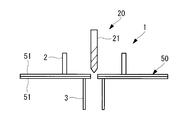
- FIG. 7 is a schematic diagram showing an operation of the clamp device and the through hole forming device according to the embodiment of the present disclosure.
- FIG. 7 is a schematic diagram showing an operation of the clamp device and the through hole forming device according to the embodiment of the present disclosure.
- FIG. 7 is a schematic diagram showing an operation of the clamp device and the through hole forming device according to the embodiment of the present disclosure.
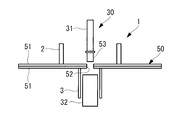
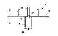
- FIG. 6 is a schematic diagram showing operations of the clamp device, the through-hole forming device, and the driving device according to the embodiment of the present disclosure.
- FIG. 6 is a schematic diagram showing operations of the clamp device, the through-hole forming device, and the driving device according to the embodiment of the present disclosure.
- FIG. 6 is a schematic diagram showing operations of the clamp device, the through-hole forming device, and the driving device according to the embodiment of the present disclosure.
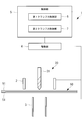
- 7 is a flowchart showing an operation of the clamp device according to the embodiment of the present disclosure.
- the clamp device 1 includes an upper support part (first support part) 2, a lower support part (second support part) 3, a drive part 4, a control part 5, and the like.
- the clamp device 1 can sandwich the work 50 arranged between the upper support portion 2 and the lower support portion 3.
- the work 50 is, for example, a stack of a plurality of plate materials 51.
- the plate material 51 is, for example, an aluminum alloy, a titanium alloy, or a composite material.
- a through hole 52 for fixing the rivet 53 is formed in the work 50, and then the rivet (fastening component) 53 is inserted into the through hole 52 and fixed.
- the upper support portion 2 includes, for example, a cylindrical member having a cylindrical shape, and is arranged on the upper surface side of the work 50.
- the upper support portion 2 supports the work 50 at the lower end of the tubular member, centering on the position where the through hole 52 is formed.
- the lower support portion 3 includes a tubular member having a cylindrical shape, for example, and is arranged on the lower surface side of the work 50.
- the lower support part 3 supports the work 50 at the upper end of the tubular member, centering on the position where the through hole 52 is formed.
- the upper support part 2 and the lower support part 3 are configured to be movable by the drive part 4 in a direction in which the work 50 is separated from or approached.
- the drill (cutting tool) 21 of the through hole forming device 20 or the anvil (pressing part) 31 of the driving device 30 passes through the tubular member of the upper support portion 2. ..
- the diameter of the tubular member of the upper support portion 2 is larger than the diameter of the tubular member of the lower support portion 3. Therefore, the position where the upper support portion 2 supports the work 50 and the position where the lower support portion 3 supports the work 50 are deviated. Therefore, as described later, when the first pressure is applied to the work 50, the work 50 may bend upward in a convex shape.
- the anvil (pressing part) 32 of the driving device 30 passes through the inside of the tubular member of the lower support part 3.
- the diameter of the tubular member is reduced to reduce the circumference of the lower support part 3 when forming the through-hole 52 and driving the rivet 53. It becomes difficult to interfere with other parts located at.
- the upper support portion 2 and the lower support portion 3 are not limited to the case where they are provided with, for example, a cylindrical member having a cylindrical shape, and the upper support portion 2 and the lower support portion 3 are centered on the position where the through hole 52 is formed.
- the work 50 may be supported at a total of two points, one point on each side of the position where the through hole 52 is formed.
- the support point of the upper support portion 2 is located outside the support point of the lower support portion 3 with respect to the position where the through hole 52 is formed. Therefore, the position where the upper support portion 2 supports the work 50 and the position where the lower support portion 3 supports the work 50 are deviated.
- the drive unit 4 is, for example, a motor and receives electric power to drive it, and moves the upper support unit 2 and the lower support unit 3 in the axial direction of the tubular members of the upper support unit 2 and the lower support unit 3, respectively.
- the control unit 5 includes, for example, a first clamping force control unit 6 and a second clamping force control unit 7.
- the upper support unit 2 and the lower support unit 3 have the predetermined first With the pressure applied to the work 50, the drive unit 4 is controlled so as to sandwich the work 50.
- the first clamping force control unit 6 moves the lower support unit 3 to a preset position.
- the lower support portion 3 is moved based on the detection result of the detection portion that detects the load applied to the work 50 by the sandwiching of the upper support portion 2 and the lower support portion 3. As a result, the predetermined first pressure is applied to the work 50.
- the movement position is recorded in advance in a memory or the like and is set for each work 50 sandwiched by the clamp device 1. Good.
- the moving position is acquired by confirming the position of the lower support portion 3 where the predetermined first pressure is applied to the work 50 in a test or simulation performed before actual manufacturing.
- the predetermined first pressure is such that the distance between the plurality of stacked plate members 51 is zero or a value close to zero, and when the through holes 52 are formed by the drill 21, the plurality of plate members 51 do not separate from each other. Set by pressure.
- the second clamping force control unit 7 includes the upper support portion 2 and the upper support portion 2 from the time when the through hole 52 is formed until the fastening component inserted in the through hole 52 by the driving device 30 is fixed to the plurality of plate members 51.
- the lower support part 3 controls the drive part 4 so as to sandwich the work 50 in a state where a predetermined second pressure lower than the first pressure is applied to the work 50.
- the second clamping force control unit 7 moves the lower support unit 3 to a preset position.
- the lower support portion 3 is moved based on the detection result of the detection portion that detects the load applied to the work 50 by the sandwiching of the upper support portion 2 and the lower support portion 3. As a result, the predetermined second pressure is applied to the work 50.
- the movement position is recorded in advance in a memory or the like and is set for each work 50 sandwiched by the clamp device 1. Good.
- the movement position is acquired by confirming the position of the lower support portion 3 in which a predetermined second pressure is applied to the work 50 in a test or simulation performed before actual manufacturing.
- the predetermined second pressure is set to a pressure at which the plurality of stacked plate members 51 do not bend in a convex shape or a concave shape.
- the control unit 5 is composed of, for example, a CPU (Central Processing Unit), a RAM (Random Access Memory), a ROM (Read Only Memory), and a computer-readable storage medium.
- a series of processes for realizing various functions are stored in a storage medium or the like in the form of a program as an example, and the CPU reads the program into a RAM or the like to execute information processing / arithmetic processing.
- the program is installed in a ROM or other storage medium in advance, provided in a state of being stored in a computer-readable storage medium, or delivered via wired or wireless communication means. Etc. may be applied.
- the computer-readable storage medium is a magnetic disk, a magneto-optical disk, a CD-ROM, a DVD-ROM, a semiconductor memory, or the like.
- step S1 the work 50 on which a plurality of plate members 51 are stacked is placed on the clamp device 1 (step S1).
- step S2 the upper support portion 2 is brought closer to the work 50 from above, and the lower end of the tubular member of the upper support portion 2 is brought into contact with the work 50 (step S2).
- the lower support portion 3 is brought closer to the work 50 from below, and the upper end of the tubular member of the lower support portion 3 is brought into contact with the work 50.
- the lower support part 3 is moved, and the work 50 is sandwiched so that the upper support part 2 and the lower support part 3 are in a state where a predetermined first pressure is applied to the work 50 (step S3).
- the distance between the plurality of stacked plate members 51 becomes zero or a value close to zero.
- the drill 21 forms a through hole 52 in the work 50 in a state where the first pressure is applied to the work 50 and the work 50 is clamped (step S4).
- the set value of the first pressure is a pressure at which the plurality of plate members 51 do not separate from each other when the through hole 52 is formed by the drill 21. Therefore, the through holes 52 can be formed through the plurality of plate members 51 in a straight line in the state where no gap is formed between the plurality of plate members 51, and the through holes 52 in which the inner surfaces of the plurality of plate members 51 are continuous are formed. ..
- the lower support part 3 is moved so that the upper support part 2 and the lower support part 3 apply a predetermined second pressure lower than the first pressure to the work 50.
- the work 50 is sandwiched so as to be in the state of being applied to (step S5).
- the plurality of stacked plate members 51 are not bent into a convex shape or a concave shape.
- the rivet 53 is inserted into the through hole 52 in a state where the second pressure is applied to the work 50, and the driving device 30 is inserted into the through hole 52. 53 is fixed to the work 50 (step S6).
- the rivets 53 are fixed by the driving device 30 in a state where the plurality of plate members 51 are sandwiched with a pressure lower than that when the through holes 52 are formed and the plurality of stacked plate members 51 are not bent in a convex shape or a concave shape. ..
- a gap is less likely to be formed between the rivet 53 and the plurality of plate materials 51, and the quality of the tack is improved. That is, in the plurality of plate members 51 fixed by the rivets 53, the load is not partially transferred from the plate members 51 to the rivets 53 in the portion other than the gap, but the load is transferred using the entire outer circumference of the rivet 53. You can
- Clamping device 2 Upper support part (first support part) 3: Lower support part (second support part) 4: Drive unit 5: Control unit 6: First clamping force control unit 7: Second clamping force control unit 20: Through hole forming device 21: Drill (cutting tool) 30: Driving device 50: Work piece 51: Plate material 52: Through hole 53: Rivets (fastening parts)
Landscapes
- Engineering & Computer Science (AREA)
- Mechanical Engineering (AREA)
- Jigs For Machine Tools (AREA)
- Drilling And Boring (AREA)
- Insertion Pins And Rivets (AREA)
Abstract
重ね合わされた複数の部材に対して貫通孔を形成した後、貫通孔に挿通された締結部品を固定したとき、締結部品と複数の部材間に隙間が形成されにくくすることを目的とする。クランプ方法は、重ね合わされた複数の部材の一面側に配置された第1支持部及び複数の部材の他面側に配置された第2支持部が、所定の第1圧力を複数の部材に付与して、複数の部材を挟むステップ(S3)と、第1圧力が付与された状態で、切削工具が複数の部材に対して貫通孔を形成するステップ(S4)と、貫通孔が形成された後、第1支持部及び第2支持部が第1圧力よりも低い所定の第2圧力を複数の部材に付与して、複数の部材を挟むステップ(S5)と、第2圧力が付与された状態で、打鋲装置が、貫通孔に挿通された締結部品を複数の部材に固定するステップ(S6)とを備える。
Description
本開示は、クランプ方法及びクランプ装置に関するものである。
航空機部品の板材(例えばスキン)を複数枚重ね合わせたり、板材に対して部品(例えばストリンガー)を取り付けたりする際、リベット等の締結部品によって複数の板材又は板材と部品(以下「複数の部材」という。)が互いに結合される。リベットを挿通するための貫通孔は、クランプ装置が複数の部材を両側から挟んだ後、ドリル等の切削加工によって形成される。その後、リベットが貫通孔に挿通され、リベット締結装置によってリベットが貫通孔に固定される。これにより、複数の部品が互いに結合される。
下記の特許文献1では、二つの部品を一体に固定するため、複数の部品を打鋲によって組み合わせることが記載され、ロボット装置が、初期締まり嵌めを実施した後、初期締まり嵌めよりも小さい力で最終締まり嵌めを実施する。
複数の部品に対して貫通孔を形成し、リベットを複数の部品に固定する間、従来の技術では、クランプ装置は、クランプ力を変更せず、同一のクランプ力で複数の部材を挟んでいる。しかし、部材の厚さや、部材を挟む際に部材を支持する位置によっては、部材が凸状又は凹状に撓む場合がある。その状態で、リベット締結装置によってリベットを打鋲しリベットを貫通孔に固定すると、貫通孔内部において部材とリベットの間に隙間が設けられてしまう。
その結果、リベットによって結合された複数の部材は、隙間以外の部分において板材からリベットへ荷重が伝達されるため、リベットの全面を用いて荷重を伝達することができない。その結果、重ね合わされた板材の強度が所定値よりも低下する。そのため、打鋲品質を維持する観点から、貫通孔内部において部材とリベットの間に隙間が設けられないように、リベットが固定されることが要求される。
本開示は、このような事情に鑑みてなされたものであって、重ね合わされた複数の部材に対して貫通孔を形成した後、貫通孔に挿通された締結部品を固定したとき、締結部品と複数の部材間に隙間が形成されにくくすることが可能なクランプ方法及びクランプ装置を提供することを目的とする。
本開示に係るクランプ方法は、重ね合わされた複数の部材の一面側に配置された第1支持部及び前記複数の部材の他面側に配置された第2支持部が、所定の第1圧力を前記複数の部材に付与して、前記複数の部材を挟むステップと、前記第1圧力が付与された状態で、切削工具が前記複数の部材に対して貫通孔を形成するステップと、前記貫通孔が形成された後、前記第1支持部及び前記第2支持部が前記第1圧力よりも低い所定の第2圧力を前記複数の部材に付与して、前記複数の部材を挟むステップと、前記第2圧力が付与された状態で、打鋲装置が、前記貫通孔に挿通された締結部品を前記複数の部材に固定するステップとを備える。
この構成によれば、貫通孔形成時は、所定の第1圧力、すなわち、比較的高い圧力で複数の部材が挟まれることから、複数の部材間に隙間が形成されない状態で、複数の部材に対して貫通孔を一気通貫に形成でき、複数の部材同士の内面が連続した貫通孔が形成される。また、所定の第2圧力、すなわち、貫通孔形成時よりも低い圧力で複数の部材が挟まれているとき、締結部品が複数の部材に固定される。このとき、複数の部材が撓まないように第1支持部と第2支持部に挟まれることによって、締結部品と複数の部材間に隙間が形成されにくくなり、打鋲品質が向上する。
本開示に係るクランプ方法において、前記第1支持部による前記複数の部材の支持位置と、前記第2支持部による前記複数の部材の支持位置とがずれていてもよい。
この構成によれば、複数の部材に第1圧力を付与すると、複数の部材が凸状又は凹状に撓む場合がある。その場合であっても、締結部品が複数の部材に固定されるときは、複数の部材が撓まないように第1支持部と第2支持部に挟まれるため、締結部品と複数の部材間に隙間が形成されにくくなり、打鋲品質が向上する。
本開示に係るクランプ装置は、重ね合わされた複数の部材の一面側に配置された第1支持部と、前記複数の部材の他面側に配置された第2支持部と、前記第1支持部及び前記第2支持部の少なくとも一つを駆動する駆動部と、前記駆動部を制御する制御部とを備え、前記制御部は、切削工具によって前記複数の部材に対して貫通孔が形成されている間、前記第1支持部及び前記第2支持部が、所定の第1圧力を前記複数の部材に付与した状態で、前記複数の部材を挟むように前記駆動部を制御する第1クランプ力制御部と、前記貫通孔が形成されてから、打鋲装置によって前記貫通孔に挿通された締結部品が前記複数の部材に固定されるまでの間、前記第1支持部及び前記第2支持部が、前記第1圧力よりも低い所定の第2圧力を前記複数の部材に付与した状態で、前記複数の部材を挟むように前記駆動部を制御する第2クランプ力制御部とを備える。
本開示によれば、重ね合わされた複数の部材に対して貫通孔を形成した後、貫通孔に挿通された締結部品を固定したとき、締結部品と複数の部材間に隙間が形成されにくくすることができる。
以下に、本開示に係る実施形態について、図面を参照して説明する。
クランプ装置1は、図1に示すように、上方支持部(第1支持部)2と、下方支持部(第2支持部)3と、駆動部4と、制御部5などを有する。クランプ装置1は、上方支持部2と下方支持部3の間に配置されたワーク50を挟むことが可能である。ワーク50は、例えば、板材51が複数枚重ね合わされたものである。板材51は、例えばアルミニウム合金、チタン合金、複合材などである。ワーク50には、リベット53を固定するための貫通孔52が形成され、その後、貫通孔52にリベット(締結部品)53が挿通されて固定される。
クランプ装置1は、図1に示すように、上方支持部(第1支持部)2と、下方支持部(第2支持部)3と、駆動部4と、制御部5などを有する。クランプ装置1は、上方支持部2と下方支持部3の間に配置されたワーク50を挟むことが可能である。ワーク50は、例えば、板材51が複数枚重ね合わされたものである。板材51は、例えばアルミニウム合金、チタン合金、複合材などである。ワーク50には、リベット53を固定するための貫通孔52が形成され、その後、貫通孔52にリベット(締結部品)53が挿通されて固定される。
上方支持部2は、例えば円筒形状を有する筒状部材を備え、ワーク50の上面側に配置される。上方支持部2は、貫通孔52を形成する位置を中心にして、筒状部材の下端でワーク50を支持する。
下方支持部3は、例えば円筒形状を有する筒状部材を備え、ワーク50の下面側に配置される。下方支持部3は、貫通孔52を形成する位置を中心にして、筒状部材の上端でワーク50を支持する。上方支持部2と下方支持部3は、駆動部4によって、ワーク50に対して離隔したり接近したりする方向に移動可能に構成される。
上方支持部2の筒状部材の内部には、図2A~図2Fに示すように、貫通孔形成装置20のドリル(切削工具)21又は打鋲装置30のアンビル(押圧部)31が通過する。上方支持部2の筒状部材の径は、下方支持部3の筒状部材の径よりも大きい。そのため、上方支持部2がワーク50を支持する位置と、下方支持部3がワーク50を支持する位置は、ずれている。そのため、後述するとおり、ワーク50に第1圧力を付与すると、ワーク50が上方に凸状に撓む場合がある。
下方支持部3の筒状部材の内部には、図2E及び図2Fに示すように、打鋲装置30のアンビル(押圧部)32が通過する。貫通孔形成装置20のドリル21が通過しない下方支持部3では、筒状部材の径を小さくすることによって、貫通孔52の形成作業及びリベット53の打鋲作業の際、下方支持部3の周囲に位置する他の部品と干渉しにくくなる。
なお、上方支持部2及び下方支持部3は、例えば円筒形状を有する筒状部材を備える場合に限定されず、上方支持部2及び下方支持部3は、貫通孔52を形成する位置を中心にして、貫通孔52を形成する位置の両側で1点ずつ、ワーク50を合計2点支持する構成を有するものでもよい。この場合、上方支持部2の支持点は、貫通孔52を形成する位置に対して、下方支持部3の支持点よりも外側に位置する。そのため、上方支持部2がワーク50を支持する位置と、下方支持部3がワーク50を支持する位置は、ずれている。
駆動部4は、例えばモータであり、電力を受けて駆動し、上方支持部2と下方支持部3の筒状部材の軸線方向に、上方支持部2と下方支持部3をそれぞれ移動させる。
制御部5は、例えば、第1クランプ力制御部6と、第2クランプ力制御部7とを備える。
第1クランプ力制御部6は、ドリル21によって複数の板材51が重ね合わされたワーク50に対して貫通孔52が形成されている間、上方支持部2及び下方支持部3が、所定の第1圧力をワーク50に付与した状態で、ワーク50を挟むように駆動部4を制御する。例えば、第1クランプ力制御部6は、予め設定された位置に、下方支持部3を移動させる。または、上方支持部2と下方支持部3の挟み込みによってワーク50に作用されている負荷を検出する検出部の検出結果に基づいて、下方支持部3を移動させる。その結果、所定の第1圧力がワーク50に付与された状態となる。
第1クランプ力制御部6によって、予め設定された位置に下方支持部3を移動させる場合、移動位置は、メモリ等において予め記録されており、クランプ装置1によって挟まれるワーク50ごとに設定されてもよい。移動位置は、実際の製造の前に行われる試験又はシミュレーションにおいて、所定の第1圧力がワーク50に付与された状態となる下方支持部3の位置を確認することで取得される。
所定の第1圧力は、重ね合わされた複数の板材51の間隔がゼロ又はゼロに近い値となり、かつ、ドリル21によって貫通孔52が形成されているとき、複数の板材51同士が離れないような圧力で設定される。
第2クランプ力制御部7は、貫通孔52が形成されてから、打鋲装置30によって貫通孔52に挿通された締結部品が複数の板材51に固定されるまでの間、上方支持部2及び下方支持部3が、第1圧力よりも低い所定の第2圧力をワーク50に付与した状態で、ワーク50を挟むように駆動部4を制御する。
例えば、第2クランプ力制御部7は、予め設定された位置に、下方支持部3を移動させる。または、上方支持部2と下方支持部3の挟み込みによってワーク50に作用されている負荷を検出する検出部の検出結果に基づいて、下方支持部3を移動させる。その結果、所定の第2圧力がワーク50に付与された状態となる。
第2クランプ力制御部7によって、予め設定された位置に下方支持部3を移動させる場合、移動位置は、メモリ等において予め記録されており、クランプ装置1によって挟まれるワーク50ごとに設定されてもよい。移動位置は、実際の製造の前に行われる試験又はシミュレーションにおいて、所定の第2圧力がワーク50に付与された状態となる下方支持部3の位置を確認することで取得される。
所定の第2圧力は、重ね合わされた複数の板材51が凸状又は凹状に撓まないような圧力で設定されることが好ましい。
制御部5は、例えば、CPU(Central Processing Unit)、RAM(Random Access Memory)、ROM(Read Only Memory)、及びコンピュータ読み取り可能な記憶媒体等から構成されている。そして、各種機能を実現するための一連の処理は、一例として、プログラムの形式で記憶媒体等に記憶されており、このプログラムをCPUがRAM等に読み出して、情報の加工・演算処理を実行することにより、各種機能が実現される。なお、プログラムは、ROMやその他の記憶媒体に予めインストールしておく形態や、コンピュータ読み取り可能な記憶媒体に記憶された状態で提供される形態、有線又は無線による通信手段を介して配信される形態等が適用されてもよい。コンピュータ読み取り可能な記憶媒体とは、磁気ディスク、光磁気ディスク、CD-ROM、DVD-ROM、半導体メモリ等である。
次に、図2A~図2F及び図3を参照して、本実施形態に係るクランプ装置1の動作について説明する。
ワーク50をクランプ装置1に挟むため、まず、図2Aに示すように、クランプ装置1に複数の板材51が重ね合わされたワーク50を載置する(ステップS1)。
ワーク50を設置した後、上方支持部2を上方からワーク50のほうへ接近させて、上方支持部2の筒状部材の下端をワーク50に接触させる(ステップS2)。
ワーク50を設置した後、上方支持部2を上方からワーク50のほうへ接近させて、上方支持部2の筒状部材の下端をワーク50に接触させる(ステップS2)。
次に、図2Bに示すように、下方支持部3を下方からワーク50のほうへ接近させて、下方支持部3の筒状部材の上端をワーク50に接触させる。下方支持部3を移動して、上方支持部2及び下方支持部3が、所定の第1圧力をワーク50に付与した状態となるように、ワーク50を挟む(ステップS3)。
所定の第1圧力がワーク50に付与されることによって、重ね合わされた複数の板材51の間隔がゼロ又はゼロに近い値となる。
そして、図2Cに示すように、第1圧力がワーク50に付与されてワーク50をクランプした状態で、ドリル21がワーク50に対して貫通孔52を形成する(ステップS4)。第1圧力の設定値は、ドリル21によって貫通孔52が形成されているとき、複数の板材51同士が離れないような圧力である。したがって、複数の板材51間に隙間が形成されない状態で、複数の板材51に対して貫通孔52を一気通貫に形成でき、複数の板材51同士の内面が連続した貫通孔52が形成される。
図2Dに示すように、貫通孔52が形成された後、下方支持部3を移動して、上方支持部2及び下方支持部3が、第1圧力よりも低い所定の第2圧力をワーク50に付与した状態となるように、ワーク50を挟む(ステップS5)。
所定の第2圧力がワーク50に付与されることによって、重ね合わされた複数の板材51が凸状又は凹状に撓まない状態となる。
次に、図2E及び図2Fに示すように、第2圧力がワーク50に付与された状態で、貫通孔52にリベット53を挿通し、打鋲装置30が、貫通孔52に挿通されたリベット53をワーク50に固定する(ステップS6)。貫通孔52の形成時よりも低い圧力で複数の板材51が挟まれて、重ね合わされた複数の板材51が凸状又は凹状に撓まない状態で、リベット53が打鋲装置30によって固定される。
その結果、リベット53と複数の板材51の間に隙間が形成されにくくなり、打鋲品質が向上する。すなわち、リベット53によって固定された複数の板材51は、隙間以外の部分において部分的に板材51からリベット53へ荷重が伝達されるのではなく、リベット53の外周全面を用いて荷重を伝達することができる。
1 :クランプ装置
2 :上方支持部(第1支持部)
3 :下方支持部(第2支持部)
4 :駆動部
5 :制御部
6 :第1クランプ力制御部
7 :第2クランプ力制御部
20 :貫通孔形成装置
21 :ドリル(切削工具)
30 :打鋲装置
50 :ワーク
51 :板材
52 :貫通孔
53 :リベット(締結部品)
2 :上方支持部(第1支持部)
3 :下方支持部(第2支持部)
4 :駆動部
5 :制御部
6 :第1クランプ力制御部
7 :第2クランプ力制御部
20 :貫通孔形成装置
21 :ドリル(切削工具)
30 :打鋲装置
50 :ワーク
51 :板材
52 :貫通孔
53 :リベット(締結部品)
Claims (3)
- 重ね合わされた複数の部材の一面側に配置された第1支持部及び前記複数の部材の他面側に配置された第2支持部が、所定の第1圧力を前記複数の部材に付与して、前記複数の部材を挟むステップと、
前記第1圧力が付与された状態で、切削工具が前記複数の部材に対して貫通孔を形成するステップと、
前記貫通孔が形成された後、前記第1支持部及び前記第2支持部が前記第1圧力よりも低い所定の第2圧力を前記複数の部材に付与して、前記複数の部材を挟むステップと、
前記第2圧力が付与された状態で、打鋲装置が、前記貫通孔に挿通された締結部品を前記複数の部材に固定するステップと、
を備えるクランプ方法。 - 前記第1支持部による前記複数の部材の支持位置と、前記第2支持部による前記複数の部材の支持位置とがずれている請求項1に記載のクランプ方法。
- 重ね合わされた複数の部材の一面側に配置された第1支持部と、前記複数の部材の他面側に配置された第2支持部と、
前記第1支持部及び前記第2支持部の少なくとも一つを駆動する駆動部と、
前記駆動部を制御する制御部と、
を備え、
前記制御部は、
切削工具によって前記複数の部材に対して貫通孔が形成されている間、前記第1支持部及び前記第2支持部が、所定の第1圧力を前記複数の部材に付与した状態で、前記複数の部材を挟むように前記駆動部を制御する第1クランプ力制御部と、
前記貫通孔が形成されてから、打鋲装置によって前記貫通孔に挿通された締結部品が前記複数の部材に固定されるまでの間、前記第1支持部及び前記第2支持部が、前記第1圧力よりも低い所定の第2圧力を前記複数の部材に付与した状態で、前記複数の部材を挟むように前記駆動部を制御する第2クランプ力制御部と、
を備えるクランプ装置。
Priority Applications (1)
| Application Number | Priority Date | Filing Date | Title |
|---|---|---|---|
| US17/269,055 US12059722B2 (en) | 2018-11-22 | 2019-11-15 | Clamping method and clamping device |
Applications Claiming Priority (2)
| Application Number | Priority Date | Filing Date | Title |
|---|---|---|---|
| JP2018219343A JP7191657B2 (ja) | 2018-11-22 | 2018-11-22 | クランプ方法及びクランプ装置 |
| JP2018-219343 | 2018-11-22 |
Publications (1)
| Publication Number | Publication Date |
|---|---|
| WO2020105552A1 true WO2020105552A1 (ja) | 2020-05-28 |
Family
ID=70774026
Family Applications (1)
| Application Number | Title | Priority Date | Filing Date |
|---|---|---|---|
| PCT/JP2019/044839 Ceased WO2020105552A1 (ja) | 2018-11-22 | 2019-11-15 | クランプ方法及びクランプ装置 |
Country Status (3)
| Country | Link |
|---|---|
| US (1) | US12059722B2 (ja) |
| JP (1) | JP7191657B2 (ja) |
| WO (1) | WO2020105552A1 (ja) |
Families Citing this family (1)
| Publication number | Priority date | Publication date | Assignee | Title |
|---|---|---|---|---|
| JP7326360B2 (ja) * | 2021-02-08 | 2023-08-15 | 三菱重工業株式会社 | 支持ユニットおよび打鋲装置 |
Citations (4)
| Publication number | Priority date | Publication date | Assignee | Title |
|---|---|---|---|---|
| US3729801A (en) * | 1970-06-18 | 1973-05-01 | Rohr Industries Inc | Nutplate riveting device and method |
| JP2008264832A (ja) * | 2007-04-20 | 2008-11-06 | Toray Eng Co Ltd | 打鋲方法及び打鋲装置 |
| JP2008302399A (ja) * | 2007-06-08 | 2008-12-18 | Toray Eng Co Ltd | 打鋲装置 |
| JP2017205802A (ja) * | 2016-05-20 | 2017-11-24 | 三菱重工業株式会社 | 打鋲装置およびその制御方法 |
Family Cites Families (4)
| Publication number | Priority date | Publication date | Assignee | Title |
|---|---|---|---|---|
| US4858289A (en) * | 1983-05-06 | 1989-08-22 | Gemcor Engineering Corp. | Dimpling and riveting apparatus |
| US20060117547A1 (en) | 2004-12-08 | 2006-06-08 | The Boeing Company | Integral clamping-and-bucking apparatus for utilizing a constant force and installing rivet fasteners in a sheet metal joint |
| US9937549B2 (en) | 2014-07-09 | 2018-04-10 | The Boeing Company | Two-stage riveting |
| JP7023824B2 (ja) * | 2018-11-22 | 2022-02-22 | 三菱重工業株式会社 | 貫通孔形成方法及び貫通孔形成装置 |
-
2018
- 2018-11-22 JP JP2018219343A patent/JP7191657B2/ja active Active
-
2019
- 2019-11-15 US US17/269,055 patent/US12059722B2/en active Active
- 2019-11-15 WO PCT/JP2019/044839 patent/WO2020105552A1/ja not_active Ceased
Patent Citations (4)
| Publication number | Priority date | Publication date | Assignee | Title |
|---|---|---|---|---|
| US3729801A (en) * | 1970-06-18 | 1973-05-01 | Rohr Industries Inc | Nutplate riveting device and method |
| JP2008264832A (ja) * | 2007-04-20 | 2008-11-06 | Toray Eng Co Ltd | 打鋲方法及び打鋲装置 |
| JP2008302399A (ja) * | 2007-06-08 | 2008-12-18 | Toray Eng Co Ltd | 打鋲装置 |
| JP2017205802A (ja) * | 2016-05-20 | 2017-11-24 | 三菱重工業株式会社 | 打鋲装置およびその制御方法 |
Also Published As
| Publication number | Publication date |
|---|---|
| JP2020082260A (ja) | 2020-06-04 |
| US20210237144A1 (en) | 2021-08-05 |
| JP7191657B2 (ja) | 2022-12-19 |
| US12059722B2 (en) | 2024-08-13 |
Similar Documents
| Publication | Publication Date | Title |
|---|---|---|
| US11717914B2 (en) | Tooling for holding thin metal parts making up a hollow structure in order to enable them to be friction-welded together | |
| JP7684900B2 (ja) | 摩擦攪拌点接合装置、摩擦攪拌点接合された被接合物、及びショルダ部材 | |
| JP6746709B2 (ja) | 部品製造方法及び部品製造システム | |
| US20120055910A1 (en) | Spot-welding method and spot-welding device | |
| JP7094678B2 (ja) | 工作物の製造方法 | |
| WO2019049894A1 (ja) | 複動式摩擦攪拌点接合方法 | |
| US10976110B2 (en) | Plate laminate type heat exchanger | |
| CN106181139A (zh) | 结构部件和制造这种部件的方法 | |
| JP2011115857A (ja) | 摩擦撹拌接合装置 | |
| JP2019048306A (ja) | 複動式摩擦攪拌点接合装置用クランプ部材、複動式摩擦攪拌点接合装置、及び、複動式摩擦攪拌点接合方法 | |
| WO2019163620A1 (ja) | 被加工物の支持装置及び被加工物の支持方法 | |
| JP7191657B2 (ja) | クランプ方法及びクランプ装置 | |
| JP5966849B2 (ja) | 車両用部品の製造方法 | |
| EP4520454A1 (en) | Joining device with clamping device and joining method | |
| JP4172343B2 (ja) | 摩擦スポット接合方法 | |
| JP5959200B2 (ja) | レーザー溶接器具および二つの溶接物を溶接するための構成および当該構成を作動させるための方法 | |
| JP4517760B2 (ja) | 摩擦点接合方法及びその装置 | |
| JP2005132003A (ja) | 積層体の製造方法およびその装置 | |
| JP5643359B2 (ja) | スポット溶接装置 | |
| US20230201910A1 (en) | Rivet joining method and joining processing apparatus | |
| KR102018958B1 (ko) | 이종소재 박판을 접합하기 위한 슬라이딩 클린칭 장치 및 그 클린칭 장치를 이용한 이종소재 박판 접합방법 | |
| KR20170102114A (ko) | 이종 금속의 레이저 용접장치 | |
| EP1738860B1 (en) | Clamp device | |
| JP5101799B2 (ja) | 圧入接合方法 | |
| JP2020099963A (ja) | 治具及び貫通孔形成方法 |
Legal Events
| Date | Code | Title | Description |
|---|---|---|---|
| 121 | Ep: the epo has been informed by wipo that ep was designated in this application |
Ref document number: 19887994 Country of ref document: EP Kind code of ref document: A1 |
|
| NENP | Non-entry into the national phase |
Ref country code: DE |
|
| 122 | Ep: pct application non-entry in european phase |
Ref document number: 19887994 Country of ref document: EP Kind code of ref document: A1 |