WO2020105487A1 - Dispositif de mesure de ph et procédé de mesure de ph - Google Patents
Dispositif de mesure de ph et procédé de mesure de phInfo
- Publication number
- WO2020105487A1 WO2020105487A1 PCT/JP2019/044110 JP2019044110W WO2020105487A1 WO 2020105487 A1 WO2020105487 A1 WO 2020105487A1 JP 2019044110 W JP2019044110 W JP 2019044110W WO 2020105487 A1 WO2020105487 A1 WO 2020105487A1
- Authority
- WO
- WIPO (PCT)
- Prior art keywords
- liquid
- line
- void
- test liquid
- supply
- Prior art date
Links
Images


Classifications
-
- G—PHYSICS
- G01—MEASURING; TESTING
- G01N—INVESTIGATING OR ANALYSING MATERIALS BY DETERMINING THEIR CHEMICAL OR PHYSICAL PROPERTIES
- G01N27/00—Investigating or analysing materials by the use of electric, electrochemical, or magnetic means
- G01N27/26—Investigating or analysing materials by the use of electric, electrochemical, or magnetic means by investigating electrochemical variables; by using electrolysis or electrophoresis
- G01N27/416—Systems
- G01N27/4161—Systems measuring the voltage and using a constant current supply, e.g. chronopotentiometry
-
- G—PHYSICS
- G01—MEASURING; TESTING
- G01N—INVESTIGATING OR ANALYSING MATERIALS BY DETERMINING THEIR CHEMICAL OR PHYSICAL PROPERTIES
- G01N27/00—Investigating or analysing materials by the use of electric, electrochemical, or magnetic means
- G01N27/26—Investigating or analysing materials by the use of electric, electrochemical, or magnetic means by investigating electrochemical variables; by using electrolysis or electrophoresis
- G01N27/28—Electrolytic cell components
- G01N27/30—Electrodes, e.g. test electrodes; Half-cells
- G01N27/38—Cleaning of electrodes
-
- G—PHYSICS
- G01—MEASURING; TESTING
- G01N—INVESTIGATING OR ANALYSING MATERIALS BY DETERMINING THEIR CHEMICAL OR PHYSICAL PROPERTIES
- G01N27/00—Investigating or analysing materials by the use of electric, electrochemical, or magnetic means
- G01N27/26—Investigating or analysing materials by the use of electric, electrochemical, or magnetic means by investigating electrochemical variables; by using electrolysis or electrophoresis
- G01N27/28—Electrolytic cell components
- G01N27/30—Electrodes, e.g. test electrodes; Half-cells
- G01N27/302—Electrodes, e.g. test electrodes; Half-cells pH sensitive, e.g. quinhydron, antimony or hydrogen electrodes
-
- G—PHYSICS
- G01—MEASURING; TESTING
- G01N—INVESTIGATING OR ANALYSING MATERIALS BY DETERMINING THEIR CHEMICAL OR PHYSICAL PROPERTIES
- G01N27/00—Investigating or analysing materials by the use of electric, electrochemical, or magnetic means
- G01N27/26—Investigating or analysing materials by the use of electric, electrochemical, or magnetic means by investigating electrochemical variables; by using electrolysis or electrophoresis
- G01N27/416—Systems
- G01N27/4166—Systems measuring a particular property of an electrolyte
- G01N27/4167—Systems measuring a particular property of an electrolyte pH
Definitions
- the present disclosure relates to a pH measuring device and a pH measuring method.
- a sensor for detecting the pH of the test solution As a pH sensor for detecting the pH of a test solution, a sensor for detecting the pH of the test solution by measuring a potential difference generated according to the difference in pH between the standard solution and the test solution is known (for example, see Patent Document 1). Due to its structural characteristics, a standard solution (for example, potassium chloride) or an electrode component (for example, metal) may flow out from such a pH sensor, and the outflow component may contaminate the test liquid. For example, when the test liquid is a chemical liquid for semiconductor processing, it is not preferable to use the test liquid contaminated by the pH measurement for semiconductor processing, because the components flowing out from the pH sensor may adversely affect the semiconductor processing.
- a standard solution for example, potassium chloride
- an electrode component for example, metal
- the pH of the sampling liquid is detected by a pH sensor, and then the sampling liquid is discharged.
- the pH of the intermediate liquid is measured when a plurality of types of chemical liquids are mixed, as the sampling amount of the intermediate liquid increases, the chemical liquid content and the content ratio in the finally obtained mixed liquid may greatly vary. Therefore, the amount of the sampling liquid used for pH measurement is preferably small from the viewpoint of suppressing the variation in the content and the content ratio of the chemical liquid in the mixed liquid.
- the present disclosure provides a technique effective in reducing the amount of test liquid used for pH measurement.
- a pH measuring device for measuring pH of a test liquid includes a void portion, a supply line communicating with the void portion, a first discharge line communicating with the void portion, and a test liquid to the supply line. And a test liquid supply valve for adjusting the supply of the test liquid, and a main body block having an integral structure for supporting the pH sensor so that the pH sensor comes into contact with the test liquid in the cavity.
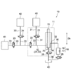
- FIG. 1 is a diagram showing an example of a flow path configuration of a pH measuring device.
- FIG. 2 is a cross-sectional view showing a specific structural example of the pH measuring device.
- FIG. 3 is a block diagram illustrating the functional configuration of the control unit.
- FIG. 4 is a block diagram schematically showing an example of the semiconductor processing system.
- a pH measuring device and a pH measuring method for measuring the pH of a test liquid will be illustrated below with reference to the drawings.
- FIG. 1 is a diagram showing an example of the flow path configuration of the pH measuring device 10.
- the pH measuring device 10 shown in FIG. 1 includes a body block 11 having an integral structure.
- the body block 11 having an integral structure basically has a structure that cannot be decomposed into a plurality of parts, and preferably has the same composition as a whole and has no seam.
- the main body block 11 has a void portion 20, a supply line 31, and a first discharge line 32. Each of the supply line 31 and the first discharge line 32 communicates with the void portion 20.
- the void portion 20 is a portion where the test liquid is stored for pH measurement.
- the pH sensor 15 supported by the main body block 11 contacts the test liquid stored in the void 20.
- the void 20 is composed of a space defined by the pH sensor 15 and the body block 11. Although the specific shape of the void 20 is not limited, the void 20 extends at least partially in the height direction Dh (that is, in the direction parallel to the gravity direction).
- the supply line 31 is connected to the void 20 and the test liquid tank 40, and is a line for feeding the test liquid from the test liquid tank 40 to the void 20.
- the test liquid supply valve 21 is provided in the supply line 31.
- the test liquid supply valve 21 adjusts the supply of the test liquid to the supply line 31.
- the illustrated test liquid supply valve 21 can adjust the inflow amount of the test liquid from the test liquid tank 40 to the supply line 31.
- the amount of the test liquid adjusted by the test liquid supply valve 21 is supplied to the void portion 20 through the supply line 31.
- the test liquid supply valve 21 has a role of extracting a part of the test liquid stored in the test liquid tank 40 as a sampling liquid, and adjusts the amount of the test liquid used for pH measurement. ..
- the orifice diameter of the test liquid supply valve 21 and the flow passage diameter (that is, the cross-sectional diameter) of the supply line 31 are small.
- the orifice diameter of the test liquid supply valve 21 and the flow channel diameter of the supply line 31 become smaller, the flow channel resistance received by the test liquid increases and the pressure loss increases. Therefore, in consideration of not only the amount of the test liquid used for pH measurement but also the characteristics such as viscosity of the test liquid and other circumstances, the orifice diameter of the test liquid supply valve 21 and the flow path diameter of the supply line 31 are determined. It is preferably decided.
- the first discharge line 32 is a line for discharging the test liquid and other liquids from the cavity 20 to the outside.
- the test liquid or the like that has overflowed from the void 20 flows into the illustrated first discharge line 32. That is, when the liquid in the void 20 exceeds the connection position of the first discharge line 32 to the void 20, the liquid flows from the void 20 into the first drain line 32.
- a communication line 35 is connected to the first discharge line 32 via a joint (not shown). The liquid that overflows from the gap 20 and flows into the first discharge line 32 is sent to the liquid storage unit 16 via the communication line 35.
- test liquid thus supplied to the void 20 via the supply line 31 is stored in the void 20 until the first discharge line 32 reaches the height position where it is connected to the void 20.
- Each of the supply line 31 and the first discharge line 32 is connected to the void 20 at a height position such that a test liquid suitable for pH measurement by the pH sensor 15 is stored in the void 20.
- the position where the first discharge line 32 connects to the void 20 is higher than the position where the supply line 31 connects to the void 20.
- the liquid storage unit 16 that communicates with the gap 20 via the communication line 35 and the first discharge line 32 constitutes an overflow detection unit 18 together with the liquid amount detection unit 17 that detects the liquid stored in the liquid storage unit 16. ..
- the specific configurations of the liquid storage unit 16 and the liquid amount detection unit 17 are not limited.
- a small tank may be used as the liquid storage section 16.
- a general level sensor may be used as the liquid amount detection unit 17.
- the liquid amount detection unit 17 may use a sensor that detects the presence or absence of a predetermined amount of liquid in the liquid storage unit 16, or a specific amount of liquid stored in the liquid storage unit 16 (for example, liquid level height). ) May be used for the sensor.
- the overflow detection unit 18 detects the liquid that has overflowed from the void portion 20 and has flowed into the liquid storage portion 16.
- the test liquid in the void 20 when the test liquid in the void 20 has not reached the connection position of the first discharge line 32 to the void 20, the test liquid does not flow into the liquid storage unit 16, and the liquid amount detection unit 17 is provided. Does not detect the liquid in the liquid reservoir 16.
- the test liquid in the void 20 reaches the connection position of the first discharge line 32 to the void 20 and flows into the first discharge line 32, the test liquid is stored in the liquid storage unit 16.
- the liquid amount detection unit 17 detects the liquid in the liquid storage unit 16.
- connection position of the first discharge line 32 with respect to the void 20 a sufficient amount of the test liquid for pH measurement is stored in the void 20
- the connection position (particularly the position in the height direction Dh) of the first discharge line 32 with respect to the void 20 is determined.
- the pH sensor 15 it is sufficient for the pH sensor 15 to appropriately detect the pH of the test liquid based on the detection result of the liquid amount detection unit 17. It is possible to determine whether or not the amount of test liquid is stored in the void 20.
- the detection result of the liquid amount detection unit 17 is sent to the control unit (see reference numeral “50” in FIG. 3), and various valves including the test liquid supply valve 21 are controlled by the control unit.
- the control unit can keep the test liquid supply valve 21 open while the liquid amount detection unit 17 does not detect that the test liquid is stored in the liquid storage unit 16. As a result, the supply line 31 is not closed by the test liquid supply valve 21, and the test liquid can flow from the test liquid tank 40 into the void 20 via the supply line 31. On the other hand, when the liquid amount detection unit 17 detects that the test liquid is stored in the liquid storage unit 16, the control unit can close the test liquid supply valve 21. As a result, the supply line 31 is closed by the test liquid supply valve 21, and the flow of the test liquid from the test liquid tank 40 into the void 20 is stopped.
- the control unit may switch the test liquid supply valve 21 to the closed state at the timing when the liquid amount detection unit 17 detects the presence of the test liquid in the liquid storage unit 16, or the predetermined amount of the test liquid is not supplied.
- the test liquid supply valve 21 may be switched to the closed state at the timing when the liquid is stored in the liquid storage section 16.
- the illustrated liquid storage unit 16 is connected to the drain line 36 via the second discharge valve 26. While the second discharge valve 26 is in the closed state, the liquid stored in the liquid storage section 16 is not discharged toward the drain line 36. On the other hand, while the second discharge valve 26 is placed in the open state, the liquid storage section 16 communicates with the drain line 36, and the liquid stored in the liquid storage section 16 is transferred to the drain tank 43 via the drain line 36. Is discharged.
- the pH sensor 15 is supported by the main body block 11 so as to come into contact with the test liquid in the void 20 and detects the pH of the test liquid stored in the void 20.
- the specific pH measuring mechanism adopted by the pH sensor 15 is not limited. Normally, the test liquid stored in the void 20 is guided to the pH detection unit (see reference numeral “15a” in FIG. 2), and between the test liquid and the standard liquid guided by the pH detection unit. The pH of the test liquid is detected by measuring the potential difference.
- a cleaning line 33 further communicates with the void 20.
- the cleaning line 33 is a line for feeding the cleaning fluid into the void portion 20, and a part of the cleaning line 33 is formed in the main body block 11.
- the illustrated cleaning line 33 is connected to the void 20 and also to the cleaning liquid tank 41 and the cleaning gas tank 42, so that the cleaning liquid and the cleaning gas can flow to the cleaning line 33 as the cleaning fluid.
- the cleaning line 33 is provided with a cleaning liquid supply valve 22, a cleaning liquid restriction valve 23, and a cleaning gas restriction valve 24.
- the cleaning liquid supply valve 22 adjusts the supply of the cleaning liquid and the cleaning gas to the cleaning line 33 and the void 20.
- the illustrated cleaning liquid supply valve 22 is provided in the connection line 30 described later in the main body block 11, and adjusts the supply of the cleaning liquid and the cleaning gas to the connection line 30.
- the cleaning liquid regulating valve 23 is provided in the cleaning line 33 from the cleaning liquid tank 41 to the cleaning liquid supply valve 22.
- the cleaning gas regulation valve 24 is provided in the cleaning line 33 from the cleaning gas tank 42 to the cleaning liquid supply valve 22.
- the illustrated main body block 11 has a connection line 30 extending from the void 20.
- the connection line 30 constitutes at least a part of the supply line 31 and at least a part of the cleaning line 33.
- the entire part of the connection line 30 that forms the supply line 31 forms a part of the cleaning line 33.
- the cleaning liquid and the cleaning gas flown in the cleaning line 33 cause not only the space 20 but also the supply line 31 (particularly The portion formed by the connection line 30) can also be washed.
- the supply line 31 is provided at a position closer to the void portion 20 than the cleaning line 33, and the total length of the supply line 31 can be effectively shortened.
- the length of the supply line 31 from the test liquid tank 40 to the void portion 20 it is possible to reduce the amount of the test liquid held in the supply line 31 at the time of pH measurement, and thus the pH. The amount of test liquid consumed by measurement can be reduced.
- the body block 11 shown in the figure further includes a second discharge line 34 that communicates with the void 20 below the first discharge line 32.
- the second discharge line 34 is a line for discharging the cleaning liquid and other liquids from the cavity 20 to the outside, and in particular, a line capable of discharging the liquid in the cavity 20 that does not overflow from the first discharge line 32.
- the body block 11 further includes a first discharge valve 25 connected to the second discharge line 34.
- the illustrated second discharge line 34 is connected to the drain line 36 via the first discharge valve 25, and the drain line 36 is connected to the drain tank 43.
- the first discharge valve 25 regulates the flow of the liquid from the void 20 into the second discharge line 34. While the first discharge valve 25 is placed in the open state, the second discharge line 34 is opened, and the liquid in the void 20 is affected by gravity, so that the liquid flows through the second discharge line 34 and the drain line 36. It is discharged to the drain tank 43. On the other hand, while the first discharge valve 25 is in the closed state, the second discharge line 34 is closed, and the liquid does not flow from the second discharge line 34 to the drain line 36.
- the second discharge line 34 and the first discharge valve 25 may not be necessarily provided as long as the liquid in the void portion 20 can be sufficiently discharged through the first discharge line 32.
- the cleaning liquid can be discharged through both the first discharge line 32 and the second discharge line 34 in order to efficiently discharge the cleaning liquid.
- the liquid in the void portion 20 may be discharged only by the first discharge line 32 without providing the second discharge line 34. Further, depending on the characteristics such as the viscosity of the test liquid, it may not be necessary to clean the void 20 and the supply line 31 with the cleaning liquid.
- the liquid (especially the test liquid) in the void 20 can be sufficiently discharged only by the first discharge line 32 without providing the second discharge line 34 in the main body block 11.
- whether or not to discharge the liquid from the gap 20 via the second discharge line 34 may be determined according to the characteristics of the liquid (particularly the test liquid) that flows into the gap 20.
- FIG. 2 is a cross-sectional view showing a specific structural example of the pH measuring device 10.
- the flow channel of the pH measuring device 10 shown in FIG. 2 corresponds to the flow channel structure shown in FIG. 1, and detailed description of the items already described above will be omitted.
- FIG. 2 mainly shows the body block 11 and the pH sensor 15. Elements such as the overflow detection unit 18, the test liquid tank 40, the cleaning liquid tank 41, and the cleaning gas tank 42 shown in FIG. 1 are omitted in FIG.
- the first discharge valve 25 is not shown in FIG. 2, in the pH measuring device 10 shown in FIG. 2, the first discharge valve 25 is horizontal (that is, vertical to the height direction Dh) with respect to the second discharge line 34. Direction). That is, since the first discharge valve 25 is provided at a position hidden by the body block 11 shown in FIG. 2 and not visible, it is not shown in FIG. 2 and is actually provided in the body block 11.
- the integrated body block 11 has a measuring unit 12 and an introducing unit 13.
- the illustrated measuring unit 12 and introducing unit 13 are made of the same material, and are seamlessly adjacent to each other.
- the measurement unit 12 is provided with the void 20, the first discharge line 32, and the second discharge line 34, and the pH sensor 15 is supported by the measurement unit 12.
- the introduction portion 13 is provided with a test liquid supply valve 21 and a cleaning liquid supply valve 22.
- the supply line 31 and the cleaning line 33 (including the connection line 30) communicating with the void 20 are provided over both the measuring unit 12 and the introducing unit 13.
- an adapter 19 is interposed between the main body block 11 and the pH sensor 15.
- the adapter 19 functions as an attachment and fixedly supports the pH sensor 15 while being fixedly supported by the main body block 11.
- the method of supporting the pH sensor 15 by the adapter 19 and the method of supporting the adapter 19 by the main body block 11 are not limited, and any fixing means such as interference fitting or screw fitting can be used.
- the void 20 is partitioned by the pH sensor 15 and the body block 11, and the cross-sectional diameter and volume of the void 20 are determined according to the distance between the body block 11 and the pH sensor 15. Therefore, the relative position of the pH sensor 15 with respect to the main body block 11 is determined according to the adapter 19, and the volume of the void 20 is adjusted. Therefore, by appropriately selecting the characteristics of the adapter 19 to be actually used, an appropriate interval according to the characteristics (viscosity, etc.) of the test liquid is secured between the pH sensor 15 and the main body block 11, and the void portion 20 is provided.
- the cross-sectional diameter and volume of the can be optimized.
- the volume of the void 20 is small.
- an appropriate adapter that allows the void portion 20 to have a cross-sectional diameter and a volume that are determined in consideration of the consumption amount of the test liquid by the pH measurement, the characteristics such as the viscosity of the test liquid, and other circumstances. 19 are selected.
- the pH sensor 15 has a pH detection unit 15a and an introduction line 15b connected to the pH detection unit 15a.
- a part of the test liquid stored in the void 20 is guided to the pH detector 15a via the introduction line 15b.
- the pH of the induced test liquid (strictly speaking, the potential difference between the standard liquid and the test liquid) is measured by the pH detection unit 15a.
- the first discharge line 32 is located at a position higher than the pH detection unit 15a in the height direction Dh so that the test liquid in the space 20 can reliably reach the pH detection unit 15a through the introduction line 15b. Connected to.
- FIG. 3 is a block diagram illustrating the functional configuration of the control unit 50.
- the control unit 50 receives the detection result of the pH sensor 15 and the detection result of the liquid amount detection unit 17.
- the control unit 50 also opens and closes each of the test liquid supply valve 21, the cleaning liquid supply valve 22, the cleaning liquid control valve 23, the cleaning gas control valve 24, the first discharge valve 25, and the second discharge valve 26, which are electromagnetic valves. To control.
- control unit 50 controls opening / closing of the test liquid supply valve 21 according to the detection result of the liquid amount detection unit 17. While the control unit 50 automatically opens and closes the test liquid supply valve 21 according to the detection result of the liquid amount detection unit 17, while preventing an excessive amount of test liquid from being supplied to the void 20, A sufficient amount of test liquid can be supplied to the cavity 20.
- the control unit 50 can use the detection result of the pH sensor 15 and the detection result of the liquid amount detection unit 17 for any purpose.
- the control unit 50 may use the detection result of the liquid amount detection unit 17 in order to obtain the proper pH of the test liquid.
- the pH sensor in order to stably and accurately detect the pH of the test liquid by the pH sensor, it is preferable to immerse the pH sensor in the test liquid for a certain time (usually about 1 to 5 minutes). That is, immediately after the pH sensor is brought into contact with the test liquid, the detection result of the pH sensor is unstable, and the reliability of the detection result is lacking. Therefore, it is preferable to adopt the detection value of the pH sensor obtained after a certain period of time in which the pH sensor is in contact with the test liquid, as the pH measurement value of the test liquid.
- control unit 50 controls the pH sensor after a lapse of a predetermined time (for example, about 2 minutes) after the liquid amount detection unit 17 detects the test liquid (that is, after the test liquid supply valve 21 is switched to the closed state).
- the pH value detected by 15 can be adopted as the pH measurement value of the test liquid.
- the detection result of the pH sensor 15 may be continuously (regularly) transmitted from the pH sensor 15 to the control unit 50, or may be transmitted from the pH sensor 15 to the control unit 50 in response to a request from the control unit 50. May be done.
- the pH measuring method includes the step of flowing the test liquid from the supply line 31 toward the void 20 in the pH measuring device 10, and the pH sensor 15 contacting the test liquid in the void 20 to measure the test liquid. measuring the pH.
- test liquid supply valve 21 is placed in the open state, the cleaning liquid supply valve 22 and the first discharge valve 25 are placed in the closed state, and the void portion is provided from the test liquid tank 40 via the supply line 31.
- a test liquid (sampling liquid) is supplied to 20.
- the test liquid supply valve 21 is placed in the closed state, and the supply of the test liquid to the void 20 is stopped. Be done.
- the pH sensor 15 (specifically, the pH sensor 15). The pH value detected by the detection unit 15a) is acquired as the pH measurement value of the test liquid.
- the cleaning process of the void 20 performed when continuously measuring the pH of a plurality of types of treatment liquids is performed as follows, for example. ..
- test liquid supply valve 21 is placed in an open state
- the cleaning liquid supply valve 22 and the first discharge valve 25 are placed in a closed state
- the supply line 31 is a source of the first processing liquid (not shown; (See liquid tank 40).
- the first processing liquid is supplied to the cavity 20 via the supply line 31, and the pH of the first processing liquid is detected by the pH sensor 15.
- the test liquid supply valve 21 and the cleaning gas control valve 24 are placed in the closed state, the cleaning liquid control valve 23 and the cleaning liquid supply valve 22 are placed in the open state, and the cleaning line 33 is used.
- the cleaning liquid is supplied from the cleaning liquid tank 41 to the void 20.
- the first processing liquid remaining in the connection line 30 and the void 20 is washed away.
- the cleaning liquid overflowing from the gap 20 and flowing into the first discharge line 32 is sent to the liquid storage unit 16 via the communication line 35.
- the second discharge valve 26 By placing the second discharge valve 26 in the open state, the cleaning liquid in the liquid storage section 16 is discharged to the drain tank 43 via the drain line 36.
- the first drain valve 25 is placed in an open state, and the cleaning liquid in the void 20 is drained to the drain tank 43 via the second drain line 34 and the drain line 36.
- test liquid supply valve 21 and the cleaning liquid regulation valve 23 are placed in the closed state, the cleaning liquid supply valve 22 and the cleaning gas regulation valve 24 are placed in the open state, and the space 20 is removed from the cleaning gas tank 42 via the cleaning line 33.
- a cleaning gas compressed gas such as N 2
- the residual liquid in the connection line 30 and the void 20 can be blown off by the cleaning gas and discharged from the first discharge line 32 and / or the second discharge line 34.
- the cleaning liquid supply valve 22, the cleaning liquid control valve 23, the cleaning gas control valve 24, and the first discharge valve 25 are placed in the closed state, and the test liquid supply valve 21 is placed in the open state to supply the second processing liquid.
- a source (not shown) is connected to the supply line 31.
- the second processing liquid is supplied to the cavity 20 via the supply line 31, and the pH sensor 15 can detect the pH of the second processing liquid.
- the void 20, the supply line 31, the first discharge line 32, and the test liquid supply valve 21 are provided in the main body block 11 having an integral structure. Be done. As a result, the total length of the supply line 31 can be shortened to reduce the volume of the supply line 31, the amount of the test liquid held in the supply line 31 can be suppressed, and the test liquid supply valve 21 to the void portion 20 can be reduced. It is possible to reduce the amount of the test liquid that is sent toward.
- the present inventor based on the conventional type pH measuring device in which separate introduction block and measuring block are connected to each other via a joint, and the pH measuring device 10 including the main body block 11 having the above-described integral structure, Various simulations were performed. As a result, compared with the conventional type pH measuring device, according to the above-mentioned pH measuring device 10 including the main body block 11 having the integral structure, the amount of the test liquid (sampling liquid) used for pH measurement is about 1/10 or less. It has been found that it can be reduced to
- the void 20 By providing the void 20, the supply line 31, the first discharge line 32, and the test solution supply valve 21 in the main body block 11 having an integral structure in this manner, when measuring the pH of the test solution, It is possible to quickly feed the test liquid into the void portion 20 while suppressing the usage amount.
- the cross-sectional diameter and volume of the void 20 can be optimized according to the characteristics such as the viscosity of the test liquid. it can.
- the cross-sectional diameter and volume of the void portion 20 By optimizing the cross-sectional diameter and volume of the void portion 20, a necessary and sufficient amount of the test liquid can be stored in the void portion 20, while reducing the waste of the test liquid consumed in pH measurement. , PH measurement can be performed appropriately.
- the test liquid discharged from the cavity 20 is detected by the liquid amount detection unit 17 in the liquid storage unit 16, and the test liquid is detected according to the detection result of the liquid amount detection unit 17.
- the supply valve 21 is controlled to open and close. This makes it possible to surely fill the void 20 with the amount of the analyte required for pH measurement while suppressing the amount of the analyte to be supplied to the void 20 via the supply line 31.
- the pH measuring device 10 and the pH measuring method described above are effective in reducing the amount of the test liquid used for pH measurement, and can accurately measure the pH of the test liquid. ..
- the pH measuring device 10 and the pH measuring method described above can be applied to various devices, methods, and other related techniques, and the application target is not limited.
- the pH measuring device 10 and the pH measuring method described above can be applied to a semiconductor processing system that performs chemical liquid processing such as plating processing.
- FIG. 4 is a block diagram schematically showing an example of the semiconductor processing system 70.
- a semiconductor processing system 70 shown in FIG. 4 includes a mixed liquid tank 51, a semiconductor processing device 55, and the pH measuring device 10 shown in FIGS. 1 and 2.
- the mixed liquid tank 51 stores a mixed liquid containing a plurality of types of chemical liquids.
- a plurality of chemical liquid supply units (first chemical liquid supply unit 61, second chemical liquid supply unit 62 and third chemical liquid supply unit 63) are connected to the mixed liquid tank 51, and corresponding chemical liquids are supplied from the respective chemical liquid supply units. Supplied.
- the chemical solutions supplied from the chemical solution supply units to the mixed solution tank 51 are mixed in the mixed solution tank 51 by a stirrer (not shown), whereby the mixed solution is prepared in the mixed solution tank 51.
- the specific components of the mixed solution thus prepared are not limited.
- the mixed solution prepared in the mixed solution tank 51 may be a plating solution used for plating the semiconductor wafer.
- the semiconductor processing apparatus 55 has a mixed solution supply nozzle 56 connected to the mixed solution tank 51 via a mixed solution delivery line 52, and uses the mixed solution discharged from the mixed solution supply nozzle 56 for semiconductor processing.
- the mixed liquid for example, the plating liquid
- the mixed liquid supply nozzle 56 may be applied to the processing surface of the wafer (not shown) held in the semiconductor processing apparatus 55.
- the supply line 31 of the pH measuring device 10 is connected to the mixed solution tank 51 via the mixed solution delivery line 52.
- a part of the mixed liquid stored in the mixed liquid tank 51 is supplied to the pH measuring device 10 via the mixed liquid delivery line 52 and the supply line 31.
- the supply line 31 may be connected to the mixed solution tank 51 via a line other than the mixed solution delivery line 52.
- the mixed liquid delivery line 52 may have a branch line derived in the middle thereof, and an end portion of the branched line may be connected to the mixed liquid tank 51. In this case, since the mixed liquid flowing from the mixed liquid tank 51 into the mixed liquid delivery line 52 can be returned to the mixed liquid tank 51 via the branch line, the mixed liquid can be circulated.
- the first chemical solution from the first chemical solution supply section 61 and the second chemical solution from the second chemical solution supply section 62 are mixed in the mixed solution tank 51 to prepare an intermediate solution.
- the third chemical liquid from the third chemical liquid supply unit 63 may be added to the intermediate liquid.
- the intermediate liquid may be prepared while measuring the pH of the mixed liquid of the first chemical liquid and the second chemical liquid by the pH measuring device 10.
- the final mixed liquid may be prepared while measuring the pH of the mixed liquid of the intermediate liquid and the third chemical liquid by the pH measuring device 10. According to this preparation method, not only the final pH of the mixed solution but also the pH of the intermediate solution can be adjusted to a desired value, so that the desired mixed solution can be prepared with high accuracy.
- the pH of the test liquid can be measured using a very small amount of the test liquid (sampling liquid). Therefore, the amount of chemical liquid consumed by the pH measurement when preparing the intermediate liquid can be small, and the amount of the chemical liquid consumed by the pH measurement when preparing the final mixed liquid can be small. Thereby, it is possible to effectively prevent the content and content ratio of the chemical solution in the final mixed solution from being largely deviated from the desired content and content ratio due to the pH measurement.
- a high-quality mixed liquid can be prepared in the mixed liquid tank 51 and supplied to the semiconductor processing apparatus 55.
- a program that, when executed by a computer for controlling the operation of the pH measuring apparatus 10, causes the computer to control the pH measuring apparatus 10 to execute the above-described pH measuring method, or such a program is recorded.
- the present disclosure may be embodied as a recording medium.
Landscapes
- Chemical & Material Sciences (AREA)
- Life Sciences & Earth Sciences (AREA)
- Health & Medical Sciences (AREA)
- Biochemistry (AREA)
- Chemical Kinetics & Catalysis (AREA)
- Electrochemistry (AREA)
- Physics & Mathematics (AREA)
- Analytical Chemistry (AREA)
- Molecular Biology (AREA)
- General Health & Medical Sciences (AREA)
- General Physics & Mathematics (AREA)
- Immunology (AREA)
- Pathology (AREA)
- Investigating Or Analyzing Materials By The Use Of Electric Means (AREA)
- Cleaning Or Drying Semiconductors (AREA)
- Sampling And Sample Adjustment (AREA)
Abstract
Priority Applications (4)
| Application Number | Priority Date | Filing Date | Title |
|---|---|---|---|
| US17/295,126 US11802848B2 (en) | 2018-11-22 | 2019-11-11 | pH measuring device and pH measuring method |
| KR1020217017900A KR20210091253A (ko) | 2018-11-22 | 2019-11-11 | pH 계측 장치 및 pH 계측 방법 |
| JP2020558288A JP7128293B2 (ja) | 2018-11-22 | 2019-11-11 | pH計測装置及びpH計測方法 |
| JP2022129673A JP7342219B2 (ja) | 2018-11-22 | 2022-08-16 | pH計測装置及びpH計測方法 |
Applications Claiming Priority (2)
| Application Number | Priority Date | Filing Date | Title |
|---|---|---|---|
| JP2018-219386 | 2018-11-22 | ||
| JP2018219386 | 2018-11-22 |
Publications (1)
| Publication Number | Publication Date |
|---|---|
| WO2020105487A1 true WO2020105487A1 (fr) | 2020-05-28 |
Family
ID=70774419
Family Applications (1)
| Application Number | Title | Priority Date | Filing Date |
|---|---|---|---|
| PCT/JP2019/044110 WO2020105487A1 (fr) | 2018-11-22 | 2019-11-11 | Dispositif de mesure de ph et procédé de mesure de ph |
Country Status (4)
| Country | Link |
|---|---|
| US (1) | US11802848B2 (fr) |
| JP (2) | JP7128293B2 (fr) |
| KR (1) | KR20210091253A (fr) |
| WO (1) | WO2020105487A1 (fr) |
Families Citing this family (1)
| Publication number | Priority date | Publication date | Assignee | Title |
|---|---|---|---|---|
| US11573203B2 (en) | 2020-09-21 | 2023-02-07 | Texas Instruments Incorporated | Humidity sensor |
Citations (3)
| Publication number | Priority date | Publication date | Assignee | Title |
|---|---|---|---|---|
| JP2002005873A (ja) * | 2000-06-27 | 2002-01-09 | Matsushita Electric Ind Co Ltd | 一体型pHセンサ |
| JP2005517399A (ja) * | 2002-02-12 | 2005-06-16 | セレクトリコン アーベー | センサーの周囲の溶液環境を迅速に変化させるシステム及び方法 |
| JP2016055245A (ja) * | 2014-09-09 | 2016-04-21 | オルガノ株式会社 | 中和処理方法及び中和装置 |
Family Cites Families (6)
| Publication number | Priority date | Publication date | Assignee | Title |
|---|---|---|---|---|
| US3997420A (en) * | 1971-03-18 | 1976-12-14 | Beckman Instruments, Inc. | Automatic analyzer |
| US4151255A (en) * | 1977-10-11 | 1979-04-24 | Capuano Italo A | PH monitor with automatic buffer standardization |
| US4447775A (en) * | 1982-07-12 | 1984-05-08 | Gerber Products Company | Apparatus and method for continuous pH monitoring |
| AT392361B (de) * | 1987-06-30 | 1991-03-25 | Avl Verbrennungskraft Messtech | Analysegeraet und modul fuer ein analysegeraet |
| JP2767618B2 (ja) | 1989-08-02 | 1998-06-18 | キヤノン株式会社 | レーザー走査光学装置 |
| JP3064723U (ja) | 1999-06-09 | 2000-01-21 | 弘見 池知 | 排水処理用繊維材ブロックおよび排水処理装置 |
-
2019
- 2019-11-11 KR KR1020217017900A patent/KR20210091253A/ko active Search and Examination
- 2019-11-11 WO PCT/JP2019/044110 patent/WO2020105487A1/fr active Application Filing
- 2019-11-11 JP JP2020558288A patent/JP7128293B2/ja active Active
- 2019-11-11 US US17/295,126 patent/US11802848B2/en active Active
-
2022
- 2022-08-16 JP JP2022129673A patent/JP7342219B2/ja active Active
Patent Citations (3)
| Publication number | Priority date | Publication date | Assignee | Title |
|---|---|---|---|---|
| JP2002005873A (ja) * | 2000-06-27 | 2002-01-09 | Matsushita Electric Ind Co Ltd | 一体型pHセンサ |
| JP2005517399A (ja) * | 2002-02-12 | 2005-06-16 | セレクトリコン アーベー | センサーの周囲の溶液環境を迅速に変化させるシステム及び方法 |
| JP2016055245A (ja) * | 2014-09-09 | 2016-04-21 | オルガノ株式会社 | 中和処理方法及び中和装置 |
Also Published As
| Publication number | Publication date |
|---|---|
| US20220018802A1 (en) | 2022-01-20 |
| KR20210091253A (ko) | 2021-07-21 |
| JP2022163196A (ja) | 2022-10-25 |
| JP7342219B2 (ja) | 2023-09-11 |
| US11802848B2 (en) | 2023-10-31 |
| JPWO2020105487A1 (ja) | 2021-09-30 |
| JP7128293B2 (ja) | 2022-08-30 |
Similar Documents
| Publication | Publication Date | Title |
|---|---|---|
| TWI441253B (zh) | A substrate processing apparatus and a substrate processing method | |
| JP5152406B2 (ja) | 液体クロマトグラフ | |
| JP7342219B2 (ja) | pH計測装置及びpH計測方法 | |
| US20040033169A1 (en) | Slide stainer with controlled fluid flow | |
| JP7455142B2 (ja) | 自動分析装置 | |
| KR100886864B1 (ko) | 약액 공급시스템 및 약액 공급방법 | |
| US8286482B2 (en) | Process-liquid supply mechanism and process-liquid supply method | |
| KR20100092382A (ko) | 처리액 공급 시스템 및 처리액 공급 방법 | |
| US10160013B2 (en) | Rinsing bath and substrate cleaning method using such rinsing bath | |
| TWI679696B (zh) | 基板處理裝置與基板處理方法 | |
| KR100742367B1 (ko) | 약액 혼합 공급장치 | |
| JP2010080715A (ja) | 濃度制御系の故障検知方法及びそれを用いた基板処理装置 | |
| KR101040694B1 (ko) | 처리액 공급 방법 및 장치 | |
| JP4553107B2 (ja) | 排水分別方法及び装置 | |
| KR20090067456A (ko) | 액체소스 자동충진 시스템 및 그의 충진방법 | |
| JP2005160336A (ja) | 流水式魚類試験装置 | |
| US6640996B2 (en) | Method and apparatus for online switching between supply vessels | |
| WO2023112474A1 (fr) | Dispositif de mesure de la qualité de l'eau | |
| US6024922A (en) | Method of controlling an oxygen analyzer of the Hersch galvanic type | |
| CN115083953A (zh) | 基板处理装置和基板处理方法 | |
| JP2006128173A (ja) | 処理液定量供給装置 | |
| JP3673400B2 (ja) | 基板処理装置 | |
| KR20160076726A (ko) | 니켈 농도 분석 방법 및 장치 | |
| US5914607A (en) | Apparatus and methods for analyzing a sample solution, including first and second ion detectors | |
| JPH11224873A (ja) | 基板処理装置 |
Legal Events
| Date | Code | Title | Description |
|---|---|---|---|
| 121 | Ep: the epo has been informed by wipo that ep was designated in this application |
Ref document number: 19887048 Country of ref document: EP Kind code of ref document: A1 |
|
| ENP | Entry into the national phase |
Ref document number: 2020558288 Country of ref document: JP Kind code of ref document: A |
|
| NENP | Non-entry into the national phase |
Ref country code: DE |
|
| ENP | Entry into the national phase |
Ref document number: 20217017900 Country of ref document: KR Kind code of ref document: A |
|
| 122 | Ep: pct application non-entry in european phase |
Ref document number: 19887048 Country of ref document: EP Kind code of ref document: A1 |