WO2020105426A1 - 医用画像処理装置、医用画像処理方法及び記憶媒体 - Google Patents
医用画像処理装置、医用画像処理方法及び記憶媒体Info
- Publication number
- WO2020105426A1 WO2020105426A1 PCT/JP2019/043391 JP2019043391W WO2020105426A1 WO 2020105426 A1 WO2020105426 A1 WO 2020105426A1 JP 2019043391 W JP2019043391 W JP 2019043391W WO 2020105426 A1 WO2020105426 A1 WO 2020105426A1
- Authority
- WO
- WIPO (PCT)
- Prior art keywords
- medical image
- shape
- valve
- artificial valve
- display
- Prior art date
- Legal status (The legal status is an assumption and is not a legal conclusion. Google has not performed a legal analysis and makes no representation as to the accuracy of the status listed.)
- Ceased
Links
Images







Classifications
-
- A—HUMAN NECESSITIES
- A61—MEDICAL OR VETERINARY SCIENCE; HYGIENE
- A61B—DIAGNOSIS; SURGERY; IDENTIFICATION
- A61B8/00—Diagnosis using ultrasonic, sonic or infrasonic waves
- A61B8/08—Clinical applications
- A61B8/0883—Clinical applications for diagnosis of the heart
-
- A—HUMAN NECESSITIES
- A61—MEDICAL OR VETERINARY SCIENCE; HYGIENE
- A61B—DIAGNOSIS; SURGERY; IDENTIFICATION
- A61B8/00—Diagnosis using ultrasonic, sonic or infrasonic waves
- A61B8/08—Clinical applications
- A61B8/0833—Clinical applications involving detecting or locating foreign bodies or organic structures
- A61B8/0841—Clinical applications involving detecting or locating foreign bodies or organic structures for locating instruments
-
- A—HUMAN NECESSITIES
- A61—MEDICAL OR VETERINARY SCIENCE; HYGIENE
- A61B—DIAGNOSIS; SURGERY; IDENTIFICATION
- A61B8/00—Diagnosis using ultrasonic, sonic or infrasonic waves
- A61B8/46—Ultrasonic, sonic or infrasonic diagnostic devices with special arrangements for interfacing with the operator or the patient
- A61B8/461—Displaying means of special interest
-
- A—HUMAN NECESSITIES
- A61—MEDICAL OR VETERINARY SCIENCE; HYGIENE
- A61B—DIAGNOSIS; SURGERY; IDENTIFICATION
- A61B8/00—Diagnosis using ultrasonic, sonic or infrasonic waves
- A61B8/46—Ultrasonic, sonic or infrasonic diagnostic devices with special arrangements for interfacing with the operator or the patient
- A61B8/461—Displaying means of special interest
- A61B8/463—Displaying means of special interest characterised by displaying multiple images or images and diagnostic data on one display
-
- G—PHYSICS
- G06—COMPUTING OR CALCULATING; COUNTING
- G06T—IMAGE DATA PROCESSING OR GENERATION, IN GENERAL
- G06T11/00—Two-dimensional [2D] image generation
- G06T11/60—Creating or editing images; Combining images with text
-
- G—PHYSICS
- G06—COMPUTING OR CALCULATING; COUNTING
- G06T—IMAGE DATA PROCESSING OR GENERATION, IN GENERAL
- G06T7/00—Image analysis
- G06T7/0002—Inspection of images, e.g. flaw detection
- G06T7/0012—Biomedical image inspection
-
- G—PHYSICS
- G06—COMPUTING OR CALCULATING; COUNTING
- G06T—IMAGE DATA PROCESSING OR GENERATION, IN GENERAL
- G06T7/00—Image analysis
- G06T7/50—Depth or shape recovery
-
- A—HUMAN NECESSITIES
- A61—MEDICAL OR VETERINARY SCIENCE; HYGIENE
- A61B—DIAGNOSIS; SURGERY; IDENTIFICATION
- A61B6/00—Apparatus or devices for radiation diagnosis; Apparatus or devices for radiation diagnosis combined with radiation therapy equipment
- A61B6/02—Arrangements for diagnosis sequentially in different planes; Stereoscopic radiation diagnosis
- A61B6/03—Computed tomography [CT]
-
- G—PHYSICS
- G06—COMPUTING OR CALCULATING; COUNTING
- G06T—IMAGE DATA PROCESSING OR GENERATION, IN GENERAL
- G06T2207/00—Indexing scheme for image analysis or image enhancement
- G06T2207/10—Image acquisition modality
- G06T2207/10072—Tomographic images
- G06T2207/10081—Computed x-ray tomography [CT]
-
- G—PHYSICS
- G06—COMPUTING OR CALCULATING; COUNTING
- G06T—IMAGE DATA PROCESSING OR GENERATION, IN GENERAL
- G06T2207/00—Indexing scheme for image analysis or image enhancement
- G06T2207/10—Image acquisition modality
- G06T2207/10072—Tomographic images
- G06T2207/10088—Magnetic resonance imaging [MRI]
-
- G—PHYSICS
- G06—COMPUTING OR CALCULATING; COUNTING
- G06T—IMAGE DATA PROCESSING OR GENERATION, IN GENERAL
- G06T2207/00—Indexing scheme for image analysis or image enhancement
- G06T2207/10—Image acquisition modality
- G06T2207/10132—Ultrasound image
-
- G—PHYSICS
- G06—COMPUTING OR CALCULATING; COUNTING
- G06T—IMAGE DATA PROCESSING OR GENERATION, IN GENERAL
- G06T2207/00—Indexing scheme for image analysis or image enhancement
- G06T2207/30—Subject of image; Context of image processing
- G06T2207/30004—Biomedical image processing
- G06T2207/30048—Heart; Cardiac
-
- G—PHYSICS
- G06—COMPUTING OR CALCULATING; COUNTING
- G06T—IMAGE DATA PROCESSING OR GENERATION, IN GENERAL
- G06T2207/00—Indexing scheme for image analysis or image enhancement
- G06T2207/30—Subject of image; Context of image processing
- G06T2207/30004—Biomedical image processing
- G06T2207/30101—Blood vessel; Artery; Vein; Vascular
-
- G—PHYSICS
- G06—COMPUTING OR CALCULATING; COUNTING
- G06T—IMAGE DATA PROCESSING OR GENERATION, IN GENERAL
- G06T2210/00—Indexing scheme for image generation or computer graphics
- G06T2210/41—Medical
Definitions
- the embodiment of the present invention relates to a medical image processing apparatus, a medical image processing method, and a storage medium.
- TAVI transcatheter aortic valve implantation
- the problem to be solved by the present invention is to facilitate the determination of the standard of the artificial valve to be placed.
- the medical image processing apparatus includes an acquisition unit and a control unit.
- the acquisition unit acquires a measurement value regarding the shape of the heart valve included in the medical image data.
- the control unit causes the display unit to display the measured value and a numerical value related to the shape of the artificial valve placed in the heart valve.
- FIG. 1 is a block diagram showing an example of the configuration of the ultrasonic diagnostic apparatus according to the first embodiment.
- FIG. 2 is a diagram for explaining an example of extraction processing by the extraction function according to the first embodiment.
- FIG. 3 is a diagram for explaining an example of measurement performed by the measurement function according to the first embodiment.
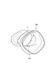
- FIG. 4A is a diagram showing an example of indwelling of the artificial valve according to the first embodiment.
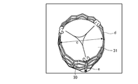
- FIG. 4B is a diagram for explaining an example of parameters indicating the shape of the artificial valve according to the first embodiment.
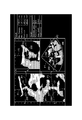
- FIG. 5A is a diagram showing an example of display by the control function according to the first embodiment.
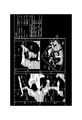
- FIG. 5B is a diagram showing an example of a display by the control function according to the first embodiment.
- FIG. 6 is a diagram showing an example of a display by the control function according to the first embodiment.
- FIG. 7 is a diagram showing an example of a display by the control function according to the first embodiment.
- FIG. 8 is a diagram showing an example of display by the control function according to the first embodiment.
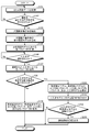
- FIG. 9 is a flowchart for explaining the procedure of processing of the ultrasonic diagnostic apparatus according to the first embodiment.
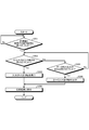
- FIG. 10 is a flowchart for explaining the procedure of processing of the ultrasonic diagnostic apparatus according to the first embodiment.
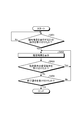
- FIG. 11 is a flowchart for explaining the procedure of processing of the ultrasonic diagnostic apparatus according to the first embodiment.
- FIG. 12 is a flowchart for explaining the procedure of processing of the ultrasonic diagnostic apparatus according to the first embodiment.
- FIG. 1 is a block diagram showing an example of the configuration of the ultrasonic diagnostic apparatus 1 according to the first embodiment.
- the ultrasonic diagnostic apparatus 1 according to this embodiment includes an ultrasonic probe 2, a display 3, an input interface 4, and a device body 5, and the ultrasonic probe 2 and the display 3 are provided. And the input interface 4 are communicatively connected to the apparatus body 5.
- the ultrasonic probe 2 is connected to the transmission / reception circuit 51 included in the device body 5.
- the ultrasonic probe 2 has, for example, a plurality of piezoelectric vibrators in the probe body, and the plurality of piezoelectric vibrators generate ultrasonic waves based on a drive signal supplied from the transmission / reception circuit 51. Further, the ultrasonic probe 2 receives the reflected wave from the subject P and converts it into an electric signal. Further, the ultrasonic probe 2 has a matching layer provided on the piezoelectric vibrator in the probe body, a backing material for preventing the ultrasonic wave from propagating backward from the piezoelectric vibrator, and the like.
- the ultrasonic probe 2 is detachably connected to the apparatus body 5.
- the ultrasonic probe 2 is a sector-type, linear-type, or convex-type ultrasonic probe.
- the transmitted ultrasonic wave is sequentially reflected by the discontinuity surface of the acoustic impedance in the internal tissue of the subject P, and the ultrasonic probe is used as a reflected wave signal. It is received by a plurality of piezoelectric vibrators included in 2.
- the amplitude of the reflected wave signal that is received depends on the difference in acoustic impedance at the discontinuous surface where the ultrasonic waves are reflected.
- the reflected wave signal when the transmitted ultrasonic pulse is reflected by the moving blood flow or the surface such as the heart wall depends on the velocity component of the moving body in the ultrasonic transmitting direction due to the Doppler effect. Receive a frequency shift.
- the ultrasonic probe 2 is an ultrasonic probe that mechanically oscillates a plurality of piezoelectric vibrators of a one-dimensional ultrasonic probe in which a plurality of piezoelectric vibrators are arranged in a row, or a plurality of piezoelectric vibrators are arranged in a grid pattern. It is an ultrasonic probe that is a two-dimensional ultrasonic probe that is arranged two-dimensionally, and is capable of scanning the subject P in three dimensions.
- the display 3 displays a GUI (Graphical User Interface) for the operator of the ultrasonic diagnostic apparatus 1 to input various setting requests using the input interface 4, or an ultrasonic image or display generated in the apparatus main body 5.
- Display information etc.
- the display information is, for example, a measurement value regarding the shape of the heart valve included in the ultrasonic image data and a numerical value indicating the shape of the artificial valve placed in the heart valve, or a shape estimation model indicating the shape of the heart valve. And artificial valve models showing the shape of the artificial valve, which will be described in detail later.
- the display 3 also displays various messages and display information to notify the operator of the processing status and processing result of the apparatus body 5. Further, the display 3 has a speaker and can also output sound.
- the input interface 4 receives operations for setting a predetermined position (for example, a region of interest), setting a display direction of an image, inputting a numerical value, and the like.
- the input interface 4 is a trackball, a switch button, a mouse, a keyboard, a touch pad for performing an input operation by touching an operation surface, a touch monitor in which a display screen and a touch pad are integrated, and a non-optical sensor. It is realized by a contact input circuit, a voice input circuit, and the like.
- the input interface 4 is connected to a processing circuit 55, which will be described later, and converts the input operation received from the operator into an electric signal and outputs the electric signal to the processing circuit 55.
- the input interface 4 is not limited to the one including physical operation parts such as a mouse and a keyboard.
- an example of the input interface includes an electric signal processing circuit that receives an electric signal corresponding to an input operation from an external input device provided separately from the device and outputs the electric signal to the processing circuit 55.
- the device body 5 has a transmission / reception circuit 51, a B-mode processing circuit 52, a Doppler processing circuit 53, a memory 54, and a processing circuit 55.
- each processing function is stored in the memory 54 in the form of a program executable by a computer.
- the transmission / reception circuit 51, the B-mode processing circuit 52, the Doppler processing circuit 53, and the processing circuit 55 are processors that realize a function corresponding to each program by reading the program from the memory 54 and executing the program. In other words, each circuit in a state where each program is read has a function corresponding to the read program.
- the transmission / reception circuit 51 has a pulse generator, a transmission delay circuit, a pulser, etc., and supplies a drive signal to the ultrasonic probe 2.
- the pulse generator repeatedly generates a rate pulse for forming a transmission ultrasonic wave at a predetermined rate frequency.
- the transmission delay circuit causes the pulse generator to generate a delay time for each piezoelectric vibrator necessary for focusing the ultrasonic waves generated by the ultrasonic probe 2 into a beam and determining the transmission directivity. Give for each rate pulse.
- the pulser applies a drive signal (drive pulse) to the ultrasonic probe 2 at a timing based on the rate pulse. That is, the transmission delay circuit arbitrarily adjusts the transmission direction of the ultrasonic wave transmitted from the surface of the piezoelectric vibrator by changing the delay time given to each rate pulse.
- the transmission / reception circuit 51 has a function capable of instantaneously changing the transmission frequency, the transmission drive voltage, etc. in order to execute a predetermined scan sequence based on an instruction from the processing circuit 55 described later.
- the change of the transmission drive voltage is realized by a linear amplifier type transmission circuit whose value can be instantaneously switched, or a mechanism for electrically switching a plurality of power supply units.
- the transmission / reception circuit 51 has a preamplifier, an A / D (Analog / Digital) converter, a reception delay circuit, an adder, etc., and performs various processes on the reflected wave signal received by the ultrasonic probe 2 to reflect it. Generate wave data.
- the preamplifier amplifies the reflected wave signal for each channel.
- the A / D converter A / D converts the amplified reflected wave signal.
- the reception delay circuit gives a delay time necessary for determining the reception directivity.
- the adder adds the reflected wave signals processed by the reception delay circuit to generate reflected wave data. By the addition process of the adder, the reflection component from the direction corresponding to the reception directivity of the reflected wave signal is emphasized, and the reception directivity and the transmission directivity form a comprehensive beam for ultrasonic transmission and reception.
- the B-mode processing circuit 52 receives the reflected wave data from the transmission / reception circuit 51, performs logarithmic amplification, envelope detection processing, and the like to generate data (B-mode data) in which the signal strength is represented by brightness of brightness. ..
- the Doppler processing circuit 53 frequency-analyzes velocity information from the reflected wave data received from the transmission / reception circuit 51, extracts blood flow, tissue, and contrast agent echo components due to the Doppler effect, and obtains moving body information such as velocity, dispersion, and power. Data extracted for multiple points (Doppler data) is generated.
- the moving body of this embodiment is a fluid such as blood flowing in a blood vessel or lymph flowing in a lymph vessel.
- the B-mode processing circuit 52 and the Doppler processing circuit 53 can process both two-dimensional reflected wave data and three-dimensional reflected wave data. That is, the B-mode processing circuit 52 generates two-dimensional B-mode data from the two-dimensional reflected wave data and three-dimensional B-mode data from the three-dimensional reflected wave data. Further, the Doppler processing circuit 53 generates two-dimensional Doppler data from the two-dimensional reflected wave data and three-dimensional Doppler data from the three-dimensional reflected wave data.
- the three-dimensional B-mode data is data to which brightness values are assigned according to the reflection intensity of the reflection source located at each of a plurality of points (sample points) set on each scanning line in the three-dimensional scanning range.
- a brightness value corresponding to the value of blood flow information (velocity, dispersion, power) is assigned to each of a plurality of points (sample points) set on each scanning line in the three-dimensional scanning range.
- the memory 54 stores the image data for display generated by the processing circuit 55.
- the memory 54 can also store data generated by the B-mode processing circuit 52 and the Doppler processing circuit 53.
- the memory 54 stores a control program for performing ultrasonic wave transmission / reception, image processing and display processing, diagnostic information (for example, patient ID, doctor's findings, etc.), and various data such as a diagnostic protocol and various body marks. To do.
- the memory 54 displays information (measurement values regarding the shape of the heart valve included in the image data and a numerical value indicating the shape of the artificial valve placed in the heart valve, a shape estimation model indicating the shape of the heart valve, and the artificial valve).
- the artificial valve model showing the shape of the is stored. The display information will be described later in detail.
- the processing circuit 55 controls the entire processing of the ultrasonic diagnostic apparatus 1. Specifically, the processing circuit 55 reads various programs corresponding to the control function 551, the image generation function 552, the extraction function 553, the generation function 554, and the measurement function 555 shown in FIG. Process.
- the control function 551 is an example of a control unit.
- the generation function 554 is an example of a generation unit.
- the measurement function 555 is an example of an acquisition unit.
- the control function 551 is based on various setting requests input by the operator through the input interface 4, various control programs and various data read from the memory 54, the transmission / reception circuit 51, the B mode processing circuit 52, and the Doppler processing circuit. The process of 53 is controlled. Further, the control function 551 controls to display the display ultrasonic image data stored in the memory 54 on the display 3. Further, the control function 551 controls so that the processing result of each function is displayed on the display 3. For example, the control function 551 controls the display information to be displayed on the display 3.
- the image generation function 552 generates ultrasonic image data from the data generated by the B-mode processing circuit 52 and the Doppler processing circuit 53. That is, the image generation function 552 generates B-mode image data in which the intensity of the reflected wave is represented by brightness from the two-dimensional B-mode data generated by the B-mode processing circuit 52.
- the B-mode image data is data in which the tissue shape in the ultrasonically scanned area is depicted.
- the image generation function 552 also generates Doppler image data representing moving body information from the two-dimensional Doppler data generated by the Doppler processing circuit 53.
- the Doppler image data is velocity image data, dispersed image data, power image data, or image data combining these.
- the Doppler image data is data indicating fluid information regarding the fluid flowing in the ultrasonically scanned area.
- the image generation function 552 generally converts (scan converts) a scanning line signal sequence of ultrasonic scanning into a scanning line signal sequence of a video format typified by a television or the like, and displays ultrasonic waves for display. Generate image data. Specifically, the image generation function 552 generates ultrasonic image data for display by performing coordinate conversion according to the scanning form of ultrasonic waves by the ultrasonic probe 2. Further, the image generation function 552 performs various image processes other than the scan conversion, such as an image process (smoothing process) for regenerating an average brightness image using a plurality of image frames after the scan conversion. Image processing (edge enhancement processing) using a differential filter is performed in the image. Further, the image generation function 552 synthesizes the ultrasonic image data with character information of various parameters, scales, body marks, and the like.
- the B-mode data and the Doppler data are ultrasonic image data before the scan conversion process, and the data generated by the image generation function 552 is the ultrasonic image data for display after the scan conversion process.
- the B-mode data and Doppler data are also called raw data.
- the image generation function 552 performs coordinate conversion on the three-dimensional B-mode data generated by the B-mode processing circuit 52 to generate three-dimensional B-mode image data.
- the image generation function 552 also performs coordinate conversion on the three-dimensional Doppler data generated by the Doppler processing circuit 53 to generate three-dimensional Doppler image data.
- the three-dimensional B-mode data and the three-dimensional Doppler data are volume data before the scan conversion process. That is, the image generation function 552 generates “three-dimensional B-mode image data or three-dimensional Doppler image data” as “volume data which is three-dimensional ultrasonic image data”.
- the image generation function 552 can perform a rendering process on the volume data in order to generate various two-dimensional image data for displaying the volume data on the display 3.
- the extraction function 553 extracts the heart valve included in the ultrasonic image data.
- the generation function 554 generates a shape estimation model indicating the shape of the heart valve extracted by the extraction function 553.
- the measurement function 555 measures the measurement value regarding the shape of the heart valve extracted by the extraction function 553. The processing by the extraction function 553, the generation function 554, and the measurement function 555 will be described later in detail.
- the ultrasonic diagnostic apparatus 1 according to the first embodiment makes it easy to determine the standard of the artificial valve to be placed. Specifically, the ultrasonic diagnostic apparatus 1 according to the first embodiment compares the measurement value regarding the shape of the heart valve extracted from the medical image data with the numerical value indicating the shape of the artificial valve placed in the heart valve. By displaying it, it becomes possible to easily determine the standard of the artificial valve to be placed.
- the specifications of the artificial valve to be indwelled are determined after accurately grasping the shapes of the valve annulus and its surrounding area.
- the standard to be selected may vary depending on the experience of the doctor, and it is not easy to appropriately determine the standard of the artificial valve to be placed. Therefore, in the ultrasonic diagnostic apparatus 1 according to the first embodiment, the standard value of the artificial valve to be placed is appropriate by comparing and displaying the measured value regarding the shape of the heart valve and the numerical value indicating the shape of the artificial valve. It is possible to facilitate the determination of whether there is any and facilitate the determination of the standard of the artificial valve to be placed.
- the extraction function 553 extracts the heart valve included in the medical image data. Specifically, the extraction function 553 extracts the peripheral region including the heart valve from the medical image data collected for the heart. For example, the extraction function 553 extracts the peripheral region including the heart valve included in the three-dimensional ultrasonic image data collected for the heart.
- FIG. 2 is a diagram for explaining an example of extraction processing by the extraction function 553 according to the first embodiment.
- FIG. 2 shows a case where the peripheral region including the aortic valve is extracted. Further, in FIG. 2, the entire heart is shown in the upper stage and the periphery of the aortic valve is shown in the lower stage.
- the peripheral region including the aortic valve extracted by the extracting function 553 will be referred to as an aortic valve complex.
- the extraction function 553 extracts the region of the left ventricle and the region of the ascending aorta as shown in the upper part of FIG. 2, and extracts the region including the boundaries of the extracted regions as the aortic valve complex 20.
- the extraction function 553 extracts the regions of the left ventricle, the right ventricle, the left atrium, the right atrium, the ascending aorta, and the pulmonary artery from the three-dimensional ultrasonic image data regarding the heart by using a known image processing technique. Further, the boundaries of each area are extracted.
- the extraction function 553 causes the anteroposterior, lateral, and vertical directions defined by the three-dimensional ultrasonic image data, and the left ventricle, right ventricle, left atrium, right atrium, ascending aorta, and Each region is extracted based on the anatomical positional relationship of each pulmonary artery.
- the aortic valve complex 20 extracted by the extraction function 553 is, for example, as shown in the lower part of FIG. 2, an annulus 21, a ST junction (sinotubular junction) 22, located between the ascending aorta 11 and the left ventricle 12. It includes Valsalva Cave 23 and annulus (also called anatomical ventriculo-arterial junction) 24.
- the Valsalva sinus 23 is a swollen portion at the origin of the ascending aorta 11.
- the ST junction 22 is a portion where the ascending aorta 11 and the Valsalva sinus 23 are joined.
- the annulus 24 is a part where the left ventricle 12 and the Valsalva sinus 23 are joined.
- the extraction function 553 can also extract other heart valves in the same manner as above.
- the extraction function 553 can extract a region of the left ventricle and a region of the left atrium, and can extract a region including a boundary between the extracted regions as a mitral valve complex.
- the extraction function 553 can extract the right ventricle region and the right atrium region, and can extract the region including the boundaries of the extracted regions as a tricuspid valve complex.
- the extraction function 553 can extract the region of the right ventricle and the region of the pulmonary artery, and the region including the boundary of each extracted region can be extracted as the pulmonary valve complex. ..
- the extraction method described above is merely an example, and the extraction function 553 can extract the aortic valve complex and the like by other existing extraction methods.
- the generation function 554 generates a heart valve model showing the shape of the heart valve extracted by the extraction function 553. Specifically, the generation function 554 generates a shape estimation model indicating the shape of the peripheral region including the heart valve extracted by the extraction function 553. For example, the extraction function 553 generates a shape estimation model of the aortic valve complex 20 extracted from the three-dimensional ultrasonic image data by the extraction function 553.
- the generation function 554 generates a three-dimensional shape estimation model showing the three-dimensional structure of the contour line of the inner wall and the contour line of the outer wall in the aortic valve complex 20 extracted by the extraction function 553.
- the shape estimation model may be generated using a standard model of the peripheral region including the heart valve.
- the memory 54 stores the standard model in advance
- the generating function 554 reads the standard model corresponding to the heart valve to be model-generated and based on the extraction result of the peripheral region.
- a shape estimation model is generated by transforming the standard model.
- the generation function 554 reads the standard model of the aortic valve complex from the memory 54 and deforms the standard model based on the shape of the aortic valve complex 20 to generate the shape estimation model of the aortic valve complex.
- the generation of the shape estimation model described above is merely an example, and the shape estimation model of the aortic valve complex or the like can be generated by other existing generation methods.
- the measurement function 555 acquires a measurement value regarding the shape of the heart valve included in the medical image data. Specifically, the measurement function 555 measures a measurement value regarding the shape of the extracted heart valve. More specifically, the measurement function 555 measures a measurement value related to the shape of the heart valve model. For example, the measurement function 555 measures various parameters indicating the shape in the shape estimation model of the aortic valve complex 20 generated by the generation function 554.
- FIG. 3 is a diagram for explaining an example of measurement performed by the measurement function 555 according to the first embodiment.
- FIG. 3 shows measurement of parameters in the shape estimation model 200 of the aortic valve complex 20 generated by the generation function 554.
- the measurement function 555 measures the diameter “a” and the circumferential length “b” of the valve annulus 210 in the shape estimation model 200.
- the measurement function 555 can measure the maximum diameter and the minimum diameter of the valve annulus as the diameter of the valve annulus 210.
- the measurement function 555 uses not only the diameter “a” and the circumferential length “b” of the valve annulus 210 but also the height of the valve annulus 210, the diameter and the circumferential length of the ascending aorta as parameters to be measured, Various parameters in the shape estimation model 200, such as the diameter and circumference of the Valsalva sinus, can be measured.
- the parameters to be measured may be arbitrarily selected by the operator, or may be changed by the operator with respect to those determined by default.
- FIG. 4A is a diagram showing an example of indwelling of the artificial valve according to the first embodiment.
- FIG. 4A shows the placement of the artificial valve 30 by the transapical approach to the aortic valve
- other approaches to the aortic valve include a transfemoral artery approach, a transsubclavian approach, and a transaortic approach. is there.
- the artificial valve 30 placed in the aortic valve is formed by attaching the valve 31 to the stent as shown in FIG. 4A.
- the parameter indicating the shape of the artificial valve 30 placed in the aortic valve is, for example, as shown in FIG. 4B, the diameter “c”, the circumferential length “d”, and the height of the valve 31 of the artificial valve 30. "E” and the like are included.
- FIG. 4B is a diagram for explaining an example of parameters indicating the shape of the artificial valve 30 according to the first embodiment.
- various parameters indicating the shape of the artificial valve are stored in the memory 54 in association with each standard of the artificial valve. That is, the memory 54 stores the diameter, the circumferential length, the height, etc. of the valve in association with each other for each standard of the artificial valve.
- the parameter indicating the shape of the artificial valve is not limited to the above-mentioned example, and any other shape of the artificial valve may be stored in association with each other.
- the artificial valve is not limited to being attached to a stent as shown in FIGS. 4A and 4B, and can be similarly used for a stentless artificial valve.
- the valve in the artificial valve may be a biological valve or a mechanical valve.
- an artificial valve model indicating the shape of the artificial valve of each standard is stored in the memory 54 and the measurement function 555 is used. It may be acquired by measuring a parameter indicating the shape in the valve model.
- the memory 54 can also store the parameter indicating the shape of the artificial valve and the artificial valve model in association with each other for each standard.
- the control function 551 causes various parameters indicating the shape of the artificial valve 30 to be displayed together with the measurement values in the shape estimation model. That is, the control function 551 causes the display 3 to display the measurement value measured by the measurement function 555 and the parameter indicating the shape of the artificial valve. Here, the control function 551 displays, as a parameter indicating the shape of the artificial valve, a numerical value indicating the shape of the artificial valve designated by the operator or a condition of the shape of the artificial valve applicable to the heart valve. ..
- FIGS. 5A and 5B are diagrams showing an example of display by the control function 551 according to the first embodiment.
- FIG. 5A shows a case where a numerical value indicating the shape of the artificial valve designated by the operator is displayed as the parameter indicating the shape of the artificial valve.
- FIG. 5B shows a case where the condition of the artificial valve shape applicable to the heart valve is displayed as the parameter indicating the artificial valve shape.
- the control function 551 three-dimensionally arranges an ultrasonic image (two images in the upper stage and an image on the lower stage on the left) of an arbitrary three slices with respect to the annulus 21.
- the three-dimensional ultrasonic image (the image on the lower right side), the measurement value of the shape estimation model (Result at the right end in the figure), and the numerical value indicating the shape of the artificial valve are displayed on the display 3.
- the control function 551 acquires each image generated from the three-dimensional ultrasonic image data obtained by extracting the aortic valve complex 20 from the image generation function 552, acquires the measurement result from the measurement function 555, and acquires the measurement result of the artificial valve.
- a numerical value indicating the shape is acquired from the memory 54 and displayed on the display 3 at the same time.
- control function 551 acquires from the memory 54 a numerical value indicating the shape of the artificial valve designated by the operator.
- the operator can display the measured value at a desired position by operating each image shown in FIG. 5A, and can display the numerical value in the standard of the artificial valve selected based on the displayed measured value.
- the upper left cross-sectional image shown in FIG. 5A shows a cross section of a plane P3 orthogonal to the plane P1 and the plane P2 in the aortic valve complex 20.
- the lower left cross-sectional image shown in FIG. 5A shows a cross section of a plane P2 orthogonal to the plane P1 and the plane P3 in the aortic valve composite 20.
- the cross-sectional image on the upper right shown in FIG. 5A shows a cross section of the plane P1 orthogonal to the plane P2 and the plane P3 in the aortic valve composite 20.
- the lower right image in FIG. 5A shows an image in which cross-sectional images of plane P1, plane P2, and plane P3 are three-dimensionally arranged.
- FIG. 5A shows an image in which cross-sectional images of plane P1, plane P2, and plane P3 are three-dimensionally arranged.
- all the planes P1 to P3 are orthogonal to each other, but not all the cross sections need to be orthogonal.
- the operator operates the straight lines P1 to P3 that define the cross section shown on the two-dimensional image, and the position and orientation of each cross section shown on the image in which the two-dimensional image is three-dimensionally arranged. By doing so, the measured value of the position where the artificial valve is placed is measured.
- the operator operates the input interface 4 to change the left and right positions and the inclination of the straight line P1 in the upper left image of FIG. 5A, so that the diameter of the valve annulus portion 21 measured by the measurement function 555. And determine the position of the circumference. Further, for example, the operator operates the input interface 4 to change the vertical position and the inclination of the straight line P2 in the upper right image of FIG. 5A or by changing the left and right positions and inclination of the straight line P3 in the upper right image of FIG. 5A, the position of the minimum diameter of the valve annulus 21 measured by the measuring function 555 is determined.
- the measurement positions of the maximum diameter and the minimum diameter may be arbitrarily designated by the operator as described above, or the shape estimation model 200 displayed in the upper right image of FIG.
- the measurement position may be determined.
- the measurement function 555 approximates the ellipse of the shape estimation model 200 to the ellipse of the shape estimation model 200 with respect to the cross section of the annulus depicted in the upper right image of FIG.
- the ellipse of the approximate shape estimation model 200 is determined.
- the measurement function 555 measures the diameters of the determined ellipses, determines the diameter showing the maximum value as the position of the maximum diameter, and determines the diameter showing the minimum value as the position of the minimum diameter.
- the control function 551 can follow the determination and change and display the positions of the straight lines P1 to P3 that define the cross section.
- the control function 551 can superimpose and display the shape estimation model 200 on each image at a corresponding position on the image. Accordingly, the operator can measure the measurement value at a desired position while simultaneously checking the ultrasonic image of the aortic valve complex 20 and the shape estimation model 200. Further, the control function 551 can receive correction of the shape of the displayed shape estimation model 200. That is, the operator can operate the input interface 4 to correct the shape estimation model 200 shown on each image in FIG. 5A. For example, the operator corrects the shape of the shape estimation model 200 generated by the generation function 554 by referring to the shape of the aortic valve complex 20 shown in the ultrasonic image on which the shape estimation model 200 is superimposed. You can As a result, it is possible to measure a measurement value with higher accuracy.
- the measurement function 555 measures the measurement value at the determined position.
- the measurement function 555 includes “maximum diameter (Max Diameter): 30.3 mm” and “minimum diameter (Min Diameter): 20 at a position corresponding to the valve annulus portion 21 in the shape estimation model 200. .3mm “,” circumferential length (Perimeter): 80.3mm “and” area (area): 483.4mm 2 "is calculated.
- the control function 551 causes the display 3 to display each calculated parameter.
- the measurement by the measurement function 555 and the display by the control function 551 can be performed following the position change by the operator. That is, the measuring function 555 can follow the operation of the input interface 4 by the operator and sequentially measure the parameter at each position.
- the control function 551 can display the sequentially measured parameters while sequentially changing the parameters along with the movements of the straight lines P1 to P3 that define the cross section.
- the operator refers to the measured parameters and selects the standard of the artificial valve to be placed in the annulus 21.
- the operator selects the artificial valve “Valve1” from the pull-down menu for selecting the artificial valve shown in FIG. 5A.
- the control function 551 reads out the numerical value stored in association with the selected artificial valve “Valve1” and displays it on the display 3.
- the control function 551 may be configured such that the artificial valve “Valve 1” has “Diameter: 20.0 mm”, “Perimeter: 62.8 mm”, “Area: 314.0 mm 2 ”, and “Area: 314.0 mm 2 ”. “Height: 15.5 mm” is read out from the memory 54 and displayed in comparison with the measured value.
- the numerical value relating to the shape of the artificial valve may be the case where the artificial valve model is read from the memory 54 and the corresponding parameter is measured.
- the control function 551 can display the condition of the artificial valve shape applicable to the heart valve as a parameter indicating the artificial valve shape.
- the measurement function 555 measures the measurement value at the determined position. To do.
- the measurement function 555 includes “maximum diameter (Max Diameter): 30.3 mm” and “minimum diameter (Min Diameter): 20 at a position corresponding to the valve annulus portion 21 in the shape estimation model 200. .3mm ",” circumferential length (Perimeter): 80.3mm “and” area (area): 483.4mm 2 "is calculated.
- the control function 551 causes the display 3 to display each calculated parameter.
- the control function 551 acquires the condition of the standard of the applicable artificial valve based on each measured parameter, and displays the acquired condition on the display 3. For example, as shown in FIG. 5B, the control function 551 may adjust the “diameter of the annulus (Ann Diameter): 18 to 20 mm” and “the diameter of the ascending aorta” of the adaptive condition “Condition 1” based on the measured parameters. (Aorta Diameter): 20-23 mm “,” Diameter of Valsalva sinus (SoV Diameter): 25-mm ",” Height of Valsalva sinus (SoV Height): 15-mm “and” circumferential length of valve annulus ( Ann Perimeter): 56.5 to 62.8 mm "is acquired. Then, the control function 551 displays the acquired parameters in comparison with the measured values.
- control function 551 can acquire the conditions of the applicable artificial valve standard by applying a predetermined rule to the measured value.
- the memory 54 stores in advance the rule applied to the measurement value.
- the control function 551 reads the rule from the memory 54 and applies the rule to the measured value of each parameter to acquire the adaptation condition.
- control function 551 compares and displays the measured value regarding the shape of the heart valve and the adaptive condition of the artificial valve placed in the heart valve. This allows the operator to determine at a glance the standard to be selected by him / herself and easily determine the standard of the artificial valve to be placed.
- the measurement value related to the shape of the heart valve and the numerical value related to the shape of the artificial valve indwelled in the heart valve are displayed in a comparative manner for placement. It enables to easily determine the standard of artificial valve.
- the ultrasonic diagnostic apparatus 1 can further display various information.
- the control function 551 causes the artificial valve model indicating the artificial valve designated by the operator and the shape estimation model to be superimposed and displayed on the corresponding position of at least one of the two-dimensional medical image and the three-dimensional medical image. You can
- FIG. 6 is a diagram showing an example of a display by the control function 551 according to the first embodiment.
- the control function 551 controls the ultrasonic image of three cross sections (two images in the upper stage and an image on the left side in the lower stage) of the annulus 21 and an image of the three slices.
- a case is shown in which a three-dimensional ultrasonic image (image on the lower right side) in which is three-dimensionally arranged and a measurement value of the shape estimation model (Result at the right end in the figure) are displayed.
- the control function 551 arranges the artificial valve model 300 showing the shape of the artificial valve 30 in a three-dimensional manner with a two-dimensional ultrasonic image of three sections and a two-dimensional ultrasonic image.
- the three-dimensional ultrasonic image is superimposed and displayed.
- the artificial valve model 300 may be a model showing the shape of the artificial valve selected by the operator or a model showing the shape of the artificial valve satisfying the adaptation condition.
- control function 551 can change the superimposed position of the artificial valve model 300 according to the operation by the operator. That is, the operator can arbitrarily change the position and orientation of the artificial valve model 300 displayed on the ultrasonic image via the input interface 4. For example, the operator can change the position or orientation of the selected artificial valve model 300 for a simple surgery simulation.
- the control function 551 follows the change by the operator and changes and displays the position and orientation of the artificial valve model 300 on the ultrasonic image.
- control function 551 can change the display mode according to the positional relationship between the artificial valve model and the shape estimation model.
- the control function 551 can emphasize and display the contact area according to the degree of contact between the artificial valve model 300 and the shape estimation model 200.
- the control function 551 emphasizes and displays a contact area having a high contact degree in the artificial valve model 300 and the shape estimation model 200 indicated by ellipses in the upper right image of FIG. 6.
- the degree of contact between the artificial valve model 300 and the shape estimation model 200 is represented by whether or not the artificial valve model 300 and the shape estimation model 200 are in contact with each other.
- the control function 551 changes the color of the contact area in contact between the artificial valve model 300 and the shape estimation model 200 on the ultrasonic image, or makes contact in the curve indicating the artificial valve model 300.
- the contact area is highlighted by thickening the line in the existing area.
- the degree of contact between the artificial valve model 300 and the shape estimation model 200 is represented by, for example, the degree of overlap of the artificial valve model 300 with the shape estimation model 200.
- the control function 551 determines whether the artificial valve model 300 should be highlighted based on how much the shape estimation model 200 is exceeded. As an example, the control function 551 causes the contour line of the artificial valve model 300 to exceed the contour line of the shape estimation model 200, and the distance thereof becomes “5%” of the distance from the center of the shape estimation model 200 to the contour line. When the corresponding distance is exceeded, it is decided to highlight. When the control function 551 determines to highlight, the color of the excess area is changed, or the line of the excess portion in the curve showing the artificial valve model 300 is thickened to exceed the excess area. Highlight the area where
- the control function 551 performs control so as to highlight each ratio in different modes.
- the control function 551 causes the contour line of the artificial valve model 300 to exceed the contour line of the shape estimation model 200, and the distance thereof corresponds to “5%” of the distance from the center of the shape estimation model 200 to the contour line.
- the area that exceeds the distance and the area that exceeds the distance corresponding to “10%” are displayed in different colors or the line thickness is changed.
- control function 551 further displays a measurement value regarding the shape of the heart valve measured based on the medical image data collected by the medical image diagnostic apparatus of a type different from the medical image diagnostic apparatus collecting the medical image data.
- the control function 551 is a heart valve of the same subject measured based on CT (Computed Tomography) image data and MRI (Magnetic Resonance Imaging) image data different from the ultrasound image data for which the shape estimation model is generated. Further display the measurement values related to the shape of.
- FIG. 7 is a diagram showing an example of a display by the control function according to the first embodiment.
- the control function 551 controls the three-section ultrasonic image (two images on the upper stage and the image on the left side on the lower stage) of the annulus 21 and the image of the three slices.
- a case is shown in which a three-dimensional ultrasonic image (image on the lower right side) in which is three-dimensionally arranged and a measurement value of the shape estimation model (Result at the right end in the figure) are displayed.
- the control function 551 causes the numerical value regarding the shape of the aortic valve of the same subject measured by the CT apparatus to be displayed in comparison with the measured value of the shape estimation model 200.
- the control function 551 has a “maximum diameter (Max Dian) of 33.0 mm”, a “minimum diameter (Min Dian) of 21.3 mm”, and a “perimeter” of “Measured by CT”. 81.7 mm "and" Area: 531.0 mm 2 "are displayed.
- control function 551 can display various parameters in “Measured by CT” by acquiring them in advance in the memory 54 and reading them.
- the control function 551 acquires the CT image data when the measurement processing is executed by the CT device and stores the CT image data in the memory 54, and the operator determines the position where various parameters regarding the shape of the shape estimation model 200 are measured. Then, the value of the parameter in the CT image data corresponding to the determined position can be displayed.
- the control function 551 performs the alignment between the CT image data stored in the memory 54 and the collected ultrasonic image data, so that the positions of the ultrasonic image data and the CT image data correspond to each other. Determine the relationship.
- the measurement function 555 extracts a position on the CT image data corresponding to the measurement position determined on the ultrasonic image data based on the determined correspondence relationship, and executes the measurement of the extracted position. For example, the measurement function 555 extracts the position on the CT image data corresponding to the position at which the “maximum diameter (Max Diameter): 30.3” of the valve annulus is measured, and calculates the distance of the extracted position as a CT image. Calculated as "Max Dian: 33.0 mm" in the data.
- the measurement on the CT image data by the measurement function 555 can be performed following the change of the position by the operator. That is, the measurement function 555 follows the operation of the input interface 4 by the operator to sequentially set the parameters of each position on the shape estimation model and the parameters of the position on the CT image data corresponding to the parameters of each position. It can be measured. Then, the control function 551 can display the parameters sequentially measured in the shape estimation model 200 and the CT image data while sequentially changing the parameters along with the movements of the straight lines P1 to P3 that define the cross section.
- the control function 551 can also display a medical image based on medical image data collected by another medical image diagnostic apparatus.
- the control function 551 can further display the CT image of the aortic valve generated based on the CT image data on the display screen shown in FIG. 7.
- control function 551 can further display a difference between a parameter measured in the shape estimation model and a parameter measured in the medical image data collected by another medical image diagnostic apparatus, an error, and the like.
- the control function 551 uses the “maximum diameter (Max Diameter): 30.3” of the valve annulus measured using the shape estimation model 200 and the “maximum diameter of the valve annulus measured using CT image data.
- the difference "2.7 mm” from “Diameter (Max Dian): 33.0 mm” can be calculated and displayed.
- control function 551 further displays the artificial valve candidates determined based on the measured values. Specifically, the control function 551 determines a suitable artificial valve standard from the relationship between the measurement value related to the shape of the shape estimation model and the adaptation condition of the artificial valve, and displays the numerical value of the determined standard. Here, the control function 551 can determine and display one or more suitable artificial valve standards.
- the control function 551 extracts one standard of the artificial valve that most satisfies the adaptive condition in each parameter, and extracts and displays the standard of the artificial valve as a candidate (recommended) of the artificial valve to be placed.
- the artificial valve that most satisfies the adaptive condition is, for example, an artificial valve that has the largest number of parameters that satisfy the condition, or an artificial valve that sets the importance for each parameter and satisfies the parameter of the highest importance.
- Means valve For example, when there are a plurality of standards that satisfy the same number of conditions, the importance is set so that the one that satisfies the condition of the diameter of the valve annulus is prioritized.
- FIG. 8 is a diagram showing an example of display by the control function according to the first embodiment.
- the control function 551 allows the control function 551 to generate an ultrasonic image of three cross sections (two images in the upper stage and an image on the lower stage in the lower stage) for the annulus 21 and an image of the three sections.
- a case is shown in which a three-dimensional ultrasonic image (image on the lower right side) in which is three-dimensionally arranged and a measurement value of the shape estimation model (Result at the right end in the figure) are displayed.
- the control function 551 uses the artificial valve “Valve1” having the highest priority and the next priority based on the relationship between the measurement value of the shape of the shape estimation model and the adaptation condition of the artificial valve.
- the artificial valve “Valve1” with high frequency is extracted, and each parameter of the extracted artificial valve is displayed in order of priority.
- the priority means, for example, the order in which the number of parameters satisfying the condition is large, or the order in which the importance is set for each parameter and the condition for the parameter having high importance is large.
- the priority is set to increase in descending order of the number of conditions of the diameter of the valve annulus and the perimeter.
- control function 551 can display various information in addition to the comparative display of the measurement value regarding the shape of the heart valve and the numerical value regarding the shape of the artificial valve indwelling in the heart valve.
- control function 551 can also perform display for showing the correspondence between the parameter name displayed on the screen or the measured value thereof and the position on the image.
- the control function 551 corresponds to the parameter name displayed on the screen or the corresponding two-dimensional ultrasonic image or three-dimensional ultrasonic image when the cursor is placed on the measured value. The part can be highlighted.
- control function 551 can change the color of the corresponding part, thicken the line of the corresponding part, display the corresponding part with a plurality of lines, or fill the corresponding part. , Highlight the relevant part.
- FIGS. 9 to 12 are flowcharts for explaining the processing procedure of the ultrasonic diagnostic apparatus 1 according to the first embodiment.
- the parameter indicating the shape of the artificial valve a numerical value indicating the shape of the artificial valve designated by the operator or the condition of the shape of the artificial valve applicable to the heart valve is displayed.
- FIG. 10 shows processing when displaying the artificial valve model.
- FIG. 11 shows processing in the case of displaying a measurement value based on medical image data acquired by another medical image diagnostic apparatus.
- FIG. 12 shows processing in the case of displaying an artificial valve suitable for placement.
- 9 to 12 show the processing when the aortic valve is targeted.
- FIGS. 11 and 12 show processing after the measurement values in the shape estimation model are displayed.
- Steps S101, S102, and S106 to S110 are steps executed by the processing circuit 55 by reading the program corresponding to the control function 551 from the memory 54.
- Step S103 is a step in which the processing circuit 55 reads the program corresponding to the extraction function 553 from the memory 54 and executes the program.
- Step S104 is a step in which the processing circuit 55 reads the program corresponding to the generation function 554 from the memory 54 and executes the program.
- Step S105 is a step in which the processing circuit 55 reads out a program corresponding to the measuring function 555 from the memory 54 and executes the program.
- Steps S201 to S205, S301 to S306, and S401 to S404 are steps executed by the processing circuit 55 by reading the program corresponding to the control function 551 from the memory 54.
- the processing circuit 55 collects the three-dimensional image data (step S101) and receives an operation to execute the analysis. It is determined (step S102).
- the ultrasonic diagnostic apparatus 1 is in a standby state until the operation is accepted (No at Step S102).
- the processing circuit 55 extracts the aortic valve complex (Step S103) and generates the shape estimation model of the aortic valve complex (Step S104). Then, the processing circuit 55 measures each parameter in the shape estimation model (step S105) and determines whether the artificial valve is selected (step S106).
- the processing circuit 55 acquires each parameter of the selected artificial valve (Step S107), and the shape estimation model, each parameter of the shape estimation model, and , Each parameter of the selected artificial valve is displayed (step S108).
- the processing circuit 55 acquires the adaptive condition based on the measured value of each parameter in the measured shape estimation model (Step S109), and the shape estimation model, Each parameter in the shape estimation model and the adaptive condition of the artificial valve are displayed (step S110).
- the processing circuit 55 collects the three-dimensional image data (step S101) and accepts an operation to execute the analysis. It is determined whether or not (step S102).
- the ultrasonic diagnostic apparatus 1 is in a standby state until the operation is accepted (No at Step S102).
- the processing circuit 55 extracts the aortic valve complex (Step S103) and generates the shape estimation model of the aortic valve complex (Step S104). Then, the processing circuit 55 measures each parameter in the shape estimation model (step S105) and determines whether the artificial valve is selected (step S106).
- the ultrasonic diagnostic apparatus 1 is in the standby state until the operation is accepted (No at Step S106).
- the processing circuit 55 acquires each parameter of the selected artificial valve (Step S107) and receives the operation for displaying the artificial valve model. It is determined whether or not (step S201).
- the processing circuit 55 displays the shape estimation model, each parameter in the shape estimation model, and each parameter in the selected artificial valve (Step S108).
- the processing circuit 55 displays the shape estimation model, each parameter in the shape estimation model, each parameter in the artificial valve, and the artificial valve model (step S202). Then, the processing circuit 55 receives an operation on the artificial valve model (step S203) and determines whether the artificial valve model contacts the shape estimation model (step S204).
- the processing circuit 55 highlights the contact area (step S205). On the other hand, when the artificial valve model does not contact the shape estimation model (No at step S204), the processing circuit 55 ends the process.
- the processing circuit 55 determines whether or not an operation of referring to the measured value is received (step S301). ..
- the ultrasonic diagnostic apparatus 1 is in a standby state until the operation is accepted (No at Step S301).
- the processing circuit 55 determines whether the manual input operation is accepted (step S302).
- the processing circuit 55 displays the input measurement value (step S303).
- the processing circuit 55 determines whether the data read operation is accepted (step S304). If the data reading operation has not been accepted (No at step S304), the processing circuit 55 returns to step S302 to determine whether or not the manual input operation has been accepted. That is, the processing circuit 55 continuously makes each determination until it accepts a manual input operation or a data reading operation.
- step S304 when the data reading operation is accepted in step S304 (Yes in step S304), the processing circuit 55 displays the read measurement value (step S305). Then, when the processing value is displayed in step S303 or step S305, the processing circuit 55 displays the comparison result between the displayed measurement value and the measurement value in the shape estimation model (step S306).
- the ultrasonic diagnostic apparatus 1 determines whether the processing circuit 55 has received an operation to execute standard estimation (step S401). ..
- the ultrasonic diagnostic apparatus 1 is in a standby state until the operation is accepted (No at Step S401).
- the processing circuit 55 displays the estimation result (candidate of artificial valve) (Step S402). Then, the processing circuit 55 determines whether or not the operation for changing the estimation condition has been received (step S403).
- the processing circuit 55 determines whether or not the end operation is received (step S404). If the end operation is accepted (Yes at step S404), the processing circuit 55 ends the process. On the other hand, if the ending operation has not been received (No at step S404), the processing circuit 55 continues to display the estimation result.
- the extraction function 553 extracts the heart valve included in the medical image data.
- the measurement function 555 measures a measurement value regarding the shape of the extracted heart valve.
- the control function 551 compares and displays the measured value and the numerical value related to the shape of the artificial valve indwelling with respect to the heart valve. Therefore, the ultrasonic diagnostic apparatus 1 according to the first embodiment can refer to the heart valve of the subject by comparing the measured value regarding the shape and the numerical value regarding the shape of the artificial valve, and Enables easy determination of standards.
- control function 551 uses the numerical value indicating the shape of the artificial valve designated by the operator or the condition of the shape of the artificial valve applicable to the heart valve as the measured value. Compare and display. Therefore, the ultrasonic diagnostic apparatus 1 according to the first embodiment can display the information for determining the standard of the artificial valve and facilitate the determination of the standard of the artificial valve to be placed. ..
- the generation function 554 generates a heart valve model (shape estimation model) indicating the shape of the heart valve extracted by the extraction function 553.
- the measurement function 555 measures a measurement value related to the shape of the heart valve model (shape estimation model). Therefore, the ultrasonic diagnostic apparatus 1 according to the first embodiment can easily measure various parameters related to the shape of the heart valve.
- the control function 551 sets the artificial valve model indicating the artificial valve designated by the operator and the heart valve model to at least one of the 2D medical image and the 3D medical image. Superimpose it on the corresponding position of. Therefore, the ultrasonic diagnostic apparatus 1 according to the first embodiment can facilitate comparison between the heart valve model (shape estimation model) and the artificial valve model, and can easily determine the standard of the artificial valve to be placed. To be able to.
- the control function 551 uses the heart valve measured based on the medical image data collected by the medical image diagnostic apparatus of the type different from the medical image diagnostic apparatus collecting the medical image data. Further display the measurement values related to the shape of. Therefore, the ultrasonic diagnostic apparatus 1 according to the first embodiment can compare measured values based on other data, and make it easier to determine the standard of the artificial valve to be placed.
- control function 551 further displays the medical image based on the medical image data collected by the different types of medical image diagnostic apparatuses. Therefore, the ultrasonic diagnostic apparatus 1 according to the first embodiment can compare images based on other data, and further facilitate determination of the standard of the artificial valve to be placed.
- control function 551 further displays the artificial valve candidates determined based on the measured values. Therefore, the ultrasonic diagnostic apparatus 1 according to the first embodiment makes it possible to further display information that supports the determination of the standard of the artificial valve to be placed.
- control function 551 causes a plurality of artificial valve candidates to be displayed in descending order of priority. Therefore, the ultrasonic diagnostic apparatus 1 according to the first embodiment makes it easy to determine the standard of the artificial valve to be placed.
- the embodiment is not limited to this, and may be applied to other heart valves such as a mitral valve and a tricuspid valve.
- the embodiment is not limited to this.
- the measurement may be performed using three-dimensional medical image data without generating the shape estimation model.
- the medical image processing apparatus according to the present application is incorporated in the ultrasonic diagnostic apparatus 1 and the ultrasonic diagnostic apparatus 1 executes various processes.
- the embodiment is not limited to this, and the medical image processing apparatus according to the present application may be incorporated in different types of medical image diagnostic apparatuses such as an X-ray CT apparatus and an MRI apparatus. In such a case, the medical image processing apparatus executes the above-mentioned processing by using the medical image data collected by the incorporated medical image diagnostic apparatus.
- CT image data is used as medical image data collected by another medical image diagnostic apparatus.
- the embodiment is not limited to this, and for example, MRI image data may be used. That is, the combination of medical image data may be any combination.
- the case where three cross sections orthogonal to the valve annulus 21 are set has been described as an example (for example, FIG. 5A and the like).
- the embodiment is not limited to this, and the cross section with respect to the valve annulus 21 can be arbitrarily set.
- the cross section passing through the root of the aortic valve leaflet for example, the plane P1 in FIG. 5A
- the cross section along the blood flow direction for example, the plane P2 in FIG. 5A
- the medical image processing apparatus according to the present application can also set these cross sections that are not orthogonal.
- the medical image processing apparatus includes a processing circuit that executes the same processing as the control function 551, the extraction function 553, the generation function 554, and the measurement function 555 described above, and a program or artificial valve corresponding to each function. And a memory for storing information regarding the above. Then, the processing circuit acquires three-dimensional medical image data from a medical image diagnostic apparatus such as an ultrasonic diagnostic apparatus or an image storage apparatus via a network, and performs the above-described processing using the acquired medical image data. Run.
- the processing circuit is a processor that realizes a function corresponding to each program by reading the program from the memory and executing the program.
- processor means, for example, a CPU (Central Processing Unit), a GPU (Graphics Processing Unit), or an application-specific integrated circuit (ASIC), a programmable logic device (for example, It means circuits such as Simple Programmable Logic Device (SPLD), Complex Programmable Logic Device (CPLD), and Field Programmable Gate Array (FPGA).
- SPLD Simple Programmable Logic Device
- CPLD Complex Programmable Logic Device
- FPGA Field Programmable Gate Array
- the processor realizes the function by reading and executing the program stored in the memory. Instead of storing the program in the memory, the program may be directly incorporated in the circuit of the processor. In this case, the processor realizes the function by reading and executing the program incorporated in the circuit.
- each processor of the present embodiment is not limited to the case where each processor is configured as a single circuit, and a plurality of independent circuits may be combined to configure one processor to realize its function. Good.
- each component of each device illustrated in the above description of the embodiments is functionally conceptual, and does not necessarily have to be physically configured as illustrated. That is, the specific form of distribution / integration of each device is not limited to that shown in the drawings, and all or part of the device may be functionally or physically distributed / arranged in arbitrary units according to various loads and usage conditions. It can be integrated and configured. Furthermore, all or arbitrary parts of each processing function performed by each device may be realized by a CPU and a program that is analyzed and executed by the CPU, or may be realized as hardware by a wired logic.
- the processing method described in the above embodiment can be realized by executing a processing program prepared in advance on a computer such as a personal computer or a workstation.
- This processing program can be distributed via a network such as the Internet. Further, this processing program is recorded in a computer-readable non-transitory recording medium such as a hard disk, a flexible disk (FD), a CD-ROM, an MO, a DVD, a flash memory such as a USB memory and an SD card memory, It can also be executed by being read from a non-transitory recording medium by a computer.
Landscapes
- Health & Medical Sciences (AREA)
- Life Sciences & Earth Sciences (AREA)
- Engineering & Computer Science (AREA)
- Physics & Mathematics (AREA)
- Radiology & Medical Imaging (AREA)
- General Health & Medical Sciences (AREA)
- Medical Informatics (AREA)
- Nuclear Medicine, Radiotherapy & Molecular Imaging (AREA)
- Biophysics (AREA)
- Public Health (AREA)
- Biomedical Technology (AREA)
- Heart & Thoracic Surgery (AREA)
- Veterinary Medicine (AREA)
- Molecular Biology (AREA)
- Surgery (AREA)
- Animal Behavior & Ethology (AREA)
- Pathology (AREA)
- General Physics & Mathematics (AREA)
- Theoretical Computer Science (AREA)
- Computer Vision & Pattern Recognition (AREA)
- Cardiology (AREA)
- Quality & Reliability (AREA)
- Ultra Sonic Daignosis Equipment (AREA)
- Apparatus For Radiation Diagnosis (AREA)
- Magnetic Resonance Imaging Apparatus (AREA)
- Prostheses (AREA)
Abstract
実施形態の医用画像処理装置(1)は、取得部(555)と、制御部(551)とを備える。取得部(555)は、医用画像データに含まれる心臓弁の形状に関する計測値を取得する。制御部(551)は、計測値と、心臓弁に対して留置される人工弁の形状に関する数値とを表示部に表示させる。
Description
本発明の実施形態は、医用画像処理装置、医用画像処理方法及び記憶媒体に関する。
従来、心臓弁膜症の治療法として、薬剤を投与する内科的治療と、新たな人口弁を取り付ける弁置換術或いは弁の一部を修復する弁形成術を行う外科的治療が知られている。また、外科的治療においては、近年、患者の負担を軽減するためにカテーテルを用いた治療法が確立している。例えば、大動脈弁狭窄症の代表的な治療法の1つとして、カテーテルを用いて大動脈弁の弁輪部に人工弁を留置する経カテーテル大動脈弁留置術(TAVI:Transcatheter Aortic Valve Implantation)が行われている。ここで、このような弁置換術では、留置する人工弁の規格を決定するために、弁輪部とその周辺部位の形状を正確に知ることが求められる。
本発明が解決しようとする課題は、留置する人工弁の規格の決定を容易にすることである。
実施形態の医用画像処理装置は、取得部と、制御部とを備える。取得部は、医用画像データに含まれる心臓弁の形状に関する計測値を取得する。制御部は、前記計測値と、前記心臓弁に対して留置される人工弁の形状に関する数値とを表示部に表示させる。
以下、添付図面を参照して、本願に係る医用画像処理装置、医用画像処理方法及び記憶媒体の実施形態を詳細に説明する。なお、本願に係る医用画像処理装置、医用画像処理方法及び記憶媒体は、以下に示す実施形態によって限定されるものではない。また、以下の説明において、同様の構成要素には共通の符号を付与するとともに、重複する説明を省略する。
(第1の実施形態)
まず、第1の実施形態における医用画像処理装置について説明する。ここで、本実施形態では、本願に係る医用画像処理装置が超音波診断装置に備えられた場合を一例に挙げて説明する。図1は、第1の実施形態に係る超音波診断装置1の構成の一例を示すブロック図である。図1に示すように、本実施形態に係る超音波診断装置1は、超音波プローブ2と、ディスプレイ3と、入力インターフェース4と、装置本体5とを有し、超音波プローブ2と、ディスプレイ3と、入力インターフェース4とが装置本体5と通信可能に接続される。
まず、第1の実施形態における医用画像処理装置について説明する。ここで、本実施形態では、本願に係る医用画像処理装置が超音波診断装置に備えられた場合を一例に挙げて説明する。図1は、第1の実施形態に係る超音波診断装置1の構成の一例を示すブロック図である。図1に示すように、本実施形態に係る超音波診断装置1は、超音波プローブ2と、ディスプレイ3と、入力インターフェース4と、装置本体5とを有し、超音波プローブ2と、ディスプレイ3と、入力インターフェース4とが装置本体5と通信可能に接続される。
超音波プローブ2は、装置本体5に含まれる送受信回路51に接続される。超音波プローブ2は、例えば、プローブ本体に複数の圧電振動子を有し、これら複数の圧電振動子は、送受信回路51から供給される駆動信号に基づき超音波を発生する。また、超音波プローブ2は、被検体Pからの反射波を受信して電気信号に変換する。また、超音波プローブ2は、プローブ本体において、圧電振動子に設けられる整合層と、圧電振動子から後方への超音波の伝播を防止するバッキング材等を有する。なお、超音波プローブ2は、装置本体5と着脱自在に接続される。例えば、超音波プローブ2は、セクタ型、リニア型又はコンベックス型などの超音波プローブである。
超音波プローブ2から被検体Pに超音波が送信されると、送信された超音波は、被検体Pの体内組織における音響インピーダンスの不連続面で次々と反射され、反射波信号として超音波プローブ2が有する複数の圧電振動子にて受信される。受信される反射波信号の振幅は、超音波が反射される不連続面における音響インピーダンスの差に依存する。なお、送信された超音波パルスが、移動している血流や心臓壁等の表面で反射された場合の反射波信号は、ドプラ効果により、移動体の超音波送信方向に対する速度成分に依存して、周波数偏移を受ける。
なお、超音波プローブ2は、複数の圧電振動子が一列で配置された1次元超音波プローブの複数の圧電振動子を機械的に揺動する超音波プローブや、複数の圧電振動子が格子状に2次元で配置された2次元超音波プローブである超音波プローブであり、被検体Pを3次元でスキャンすることが可能である。
ディスプレイ3は、超音波診断装置1の操作者が入力インターフェース4を用いて各種設定要求を入力するためのGUI(Graphical User Interface)を表示したり、装置本体5において生成された超音波画像や表示情報等を表示したりする。ここで、表示情報とは、例えば、超音波画像データに含まれる心臓弁の形状に関する計測値及び当該心臓弁に留置される人工弁の形状を示す数値や、心臓弁の形状を示す形状推定モデル及び人工弁の形状を示す人工弁モデル等であるが、これらについては後に詳述する。また、ディスプレイ3は、装置本体5の処理状況や処理結果を操作者に通知するために、各種のメッセージや表示情報を表示する。また、ディスプレイ3は、スピーカーを有し、音声を出力することもできる。
入力インターフェース4は、所定の位置(例えば、関心領域等)の設定や、画像の表示方向の設定、数値の入力等を行うための操作を受け付ける。例えば、入力インターフェース4は、トラックボール、スイッチボタン、マウス、キーボード、操作面へ触れることで入力操作を行うタッチパッド、表示画面とタッチパッドとが一体化されたタッチモニタ、光学センサを用いた非接触入力回路、及び音声入力回路等によって実現される。入力インターフェース4は、後述する処理回路55に接続されており、操作者から受け付けた入力操作を電気信号へ変換し処理回路55へと出力する。なお、本明細書において入力インターフェース4は、マウス、キーボード等の物理的な操作部品を備えるものだけに限られない。例えば、装置とは別体に設けられた外部の入力機器から入力操作に対応する電気信号を受け取り、この電気信号を処理回路55へ出力する電気信号の処理回路も入力インターフェースの例に含まれる。
装置本体5は、送受信回路51と、Bモード処理回路52と、ドプラ処理回路53と、メモリ54と、処理回路55とを有する。図1に示す超音波診断装置1においては、各処理機能がコンピュータによって実行可能なプログラムの形態でメモリ54へ記憶されている。送受信回路51、Bモード処理回路52、ドプラ処理回路53、及び、処理回路55は、メモリ54からプログラムを読み出して実行することで各プログラムに対応する機能を実現するプロセッサである。換言すると、各プログラムを読み出した状態の各回路は、読み出したプログラムに対応する機能を有することとなる。
送受信回路51は、パルス発生器、送信遅延回路、パルサ等を有し、超音波プローブ2に駆動信号を供給する。パルス発生器は、所定のレート周波数で、送信超音波を形成するためのレートパルスを繰り返し発生する。また、送信遅延回路は、超音波プローブ2から発生される超音波をビーム状に集束し、かつ送信指向性を決定するために必要な圧電振動子ごとの遅延時間を、パルス発生器が発生する各レートパルスに対し与える。また、パルサは、レートパルスに基づくタイミングで、超音波プローブ2に駆動信号(駆動パルス)を印加する。すなわち、送信遅延回路は、各レートパルスに対し与える遅延時間を変化させることで、圧電振動子面から送信される超音波の送信方向を任意に調整する。
なお、送受信回路51は、後述する処理回路55の指示に基づいて、所定のスキャンシーケンスを実行するために、送信周波数、送信駆動電圧等を瞬時に変更可能な機能を有している。特に、送信駆動電圧の変更は、瞬間にその値を切り替え可能なリニアアンプ型の発信回路、又は、複数の電源ユニットを電気的に切り替える機構によって実現される。
また、送受信回路51は、プリアンプ、A/D(Analog/Digital)変換器、受信遅延回路、加算器等を有し、超音波プローブ2が受信した反射波信号に対して各種処理を行って反射波データを生成する。プリアンプは、反射波信号をチャネル毎に増幅する。A/D変換器は、増幅された反射波信号をA/D変換する。受信遅延回路は、受信指向性を決定するために必要な遅延時間を与える。加算器は、受信遅延回路によって処理された反射波信号の加算処理を行なって反射波データを生成する。加算器の加算処理により、反射波信号の受信指向性に応じた方向からの反射成分が強調され、受信指向性と送信指向性とにより超音波送受信の総合的なビームが形成される。
Bモード処理回路52は、送受信回路51から反射波データを受信し、対数増幅、包絡線検波処理等を行なって、信号強度が輝度の明るさで表現されるデータ(Bモードデータ)を生成する。
ドプラ処理回路53は、送受信回路51から受信した反射波データから速度情報を周波数解析し、ドプラ効果による血流や組織、造影剤エコー成分を抽出し、速度、分散、パワー等の移動体情報を多点について抽出したデータ(ドプラデータ)を生成する。本実施形態の移動体は、血管内を流動する血液や、リンパ管内を流動するリンパ液等の流体である。
なお、Bモード処理回路52及びドプラ処理回路53は、2次元の反射波データ及び3次元の反射波データの両方について処理可能である。すなわち、Bモード処理回路52は、2次元の反射波データから2次元のBモードデータを生成し、3次元の反射波データから3次元のBモードデータを生成する。また、ドプラ処理回路53は、2次元の反射波データから2次元のドプラデータを生成し、3次元の反射波データから3次元のドプラデータを生成する。3次元のBモードデータは、3次元走査範囲の各走査線上で設定された複数の点(サンプル点)それぞれに位置する反射源の反射強度に応じた輝度値が割り当てられたデータとなる。また、3次元のドプラデータは、3次元走査範囲の各走査線上で設定された複数の点(サンプル点)それぞれに、血流情報(速度、分散、パワー)の値に応じた輝度値が割り当てられたデータとなる。
メモリ54は、処理回路55が生成した表示用の画像データを記憶する。また、メモリ54は、Bモード処理回路52やドプラ処理回路53が生成したデータを記憶することも可能である。また、メモリ54は、超音波送受信、画像処理及び表示処理を行なうための制御プログラムや、診断情報(例えば、患者ID、医師の所見等)や、診断プロトコルや各種ボディーマーク等の各種データを記憶する。また、メモリ54は、表示情報(画像データに含まれる心臓弁の形状に関する計測値及び当該心臓弁に留置される人工弁の形状を示す数値や、心臓弁の形状を示す形状推定モデル及び人工弁の形状を示す人工弁モデル等)を記憶する。なお、表示情報については、後に詳述する。
処理回路55は、超音波診断装置1の処理全体を制御する。具体的には、処理回路55は、図1に示す制御機能551、画像生成機能552、抽出機能553、生成機能554及び計測機能555に対応するプログラムをメモリ54から読み出して実行することで、種々の処理を行う。ここで、制御機能551は、制御部の一例である。また、生成機能554は、生成部の一例である。また、計測機能555は、取得部の一例である。
制御機能551は、入力インターフェース4を介して操作者から入力された各種設定要求や、メモリ54から読込んだ各種制御プログラム及び各種データに基づき、送受信回路51、Bモード処理回路52、ドプラ処理回路53の処理を制御する。また、制御機能551は、メモリ54が記憶する表示用の超音波画像データをディスプレイ3にて表示するように制御する。また、制御機能551は、各機能による処理結果をディスプレイ3にて表示するように制御する。例えば、制御機能551は、表示情報をディスプレイ3にて表示するように制御する。
画像生成機能552は、Bモード処理回路52及びドプラ処理回路53が生成したデータから超音波画像データを生成する。すなわち、画像生成機能552は、Bモード処理回路52が生成した2次元のBモードデータから反射波の強度を輝度にて表したBモード画像データを生成する。Bモード画像データは、超音波走査された領域内の組織形状が描出されたデータとなる。また、画像生成機能552は、ドプラ処理回路53が生成した2次元のドプラデータから移動体情報を表すドプラ画像データを生成する。ドプラ画像データは、速度画像データ、分散画像データ、パワー画像データ、又は、これらを組み合わせた画像データである。ドプラ画像データは、超音波走査された領域内を流動する流体に関する流体情報を示すデータとなる。
ここで、画像生成機能552は、一般的には、超音波走査の走査線信号列を、テレビ等に代表されるビデオフォーマットの走査線信号列に変換(スキャンコンバート)し、表示用の超音波画像データを生成する。具体的には、画像生成機能552は、超音波プローブ2による超音波の走査形態に応じて座標変換を行なうことで、表示用の超音波画像データを生成する。また、画像生成機能552は、スキャンコンバート以外に種々の画像処理として、例えば、スキャンコンバート後の複数の画像フレームを用いて、輝度の平均値画像を再生成する画像処理(平滑化処理)や、画像内で微分フィルタを用いる画像処理(エッジ強調処理)等を行なう。また、画像生成機能552は、超音波画像データに、種々のパラメータの文字情報、目盛り、ボディーマーク等を合成する。
すなわち、Bモードデータ及びドプラデータは、スキャンコンバート処理前の超音波画像データであり、画像生成機能552が生成するデータは、スキャンコンバート処理後の表示用の超音波画像データである。なお、Bモードデータ及びドプラデータは、生データ(Raw Data)とも呼ばれる。
更に、画像生成機能552は、Bモード処理回路52が生成した3次元のBモードデータに対して座標変換を行なうことで、3次元のBモード画像データを生成する。また、画像生成機能552は、ドプラ処理回路53が生成した3次元のドプラデータに対して座標変換を行なうことで、3次元のドプラ画像データを生成する。3次元のBモードデータ及び3次元のドプラデータは、スキャンコンバート処理前のボリュームデータとなる。すなわち、画像生成機能552は、「3次元のBモード画像データや3次元のドプラ画像データ」を「3次元の超音波画像データであるボリュームデータ」として生成する。
更に、画像生成機能552は、ボリュームデータをディスプレイ3にて表示するための各種の2次元画像データを生成するために、ボリュームデータに対してレンダリング処理を行なうことができる。抽出機能553は、超音波画像データに含まれる心臓弁を抽出する。生成機能554は、抽出機能553によって抽出された心臓弁の形状を示す形状推定モデルを生成する。計測機能555は、抽出機能553によって抽出された心臓弁の形状に関する計測値を計測する。なお、抽出機能553、生成機能554、及び、計測機能555による処理については、後に詳述する。
以上、第1の実施形態に係る超音波診断装置1の全体構成について説明した。かかる構成のもと、第1の実施形態に係る超音波診断装置1は、留置する人工弁の規格の決定を容易にすることを可能にする。具体的には、第1の実施形態に係る超音波診断装置1は、医用画像データから抽出した心臓弁の形状に関する計測値と、当該心臓弁に留置する人工弁の形状を示す数値とを比較表示することで、留置する人工弁の規格の決定を容易にすることを可能にする。
上述したように、弁置換術では、弁輪部とその周辺部位の形状を正確に把握したうえで、留置する人工弁の規格を決定する。ここで、人工弁は、種々の規格があるため、その中から適切な規格を選択することが、困難な場合がある。また、選択される規格が、医師の経験によって異なる場合があり、留置する人工弁の規格を適切に決定することは容易ではない。そこで、第1の実施形態に係る超音波診断装置1においては、心臓弁の形状に関する計測値と、人工弁の形状を示す数値とを比較表示させることで、留置する人工弁の規格が適切であるかの判断を容易にさせ、留置する人工弁の規格の決定を容易にすることを可能にする。
以下、第1の実施形態に係る超音波診断装置1の詳細について説明する。抽出機能553は、医用画像データに含まれる心臓弁を抽出する。具体的には、抽出機能553は、心臓を対象として収集された医用画像データから心臓弁を含む周辺領域を抽出する。例えば、抽出機能553は、心臓を対象として収集された3次元の超音波画像データに含まれる心臓弁を含む周辺領域を抽出する。
図2は、第1の実施形態に係る抽出機能553による抽出処理の一例を説明するための図である。ここで、図2においては、大動脈弁を含む周辺領域を抽出する場合を示す。また、図2においては、上段に心臓全体を示し、下段に大動脈弁の周辺を示す。なお、以下では、抽出機能553によって抽出される大動脈弁を含む周辺領域を大動脈弁複合体と記載する。
例えば、抽出機能553は、図2の上段に示すように、左心室の領域及び上行大動脈の領域を抽出し、抽出した各領域の境界を含む領域を大動脈弁複合体20として抽出する。ここで、抽出機能553は、公知の画像処理技術を用いて、心臓に関する3次元の超音波画像データから、左心室、右心室、左心房、右心房、上行大動脈及び肺動脈それぞれの領域を抽出し、さらに、各領域の境界を抽出する。このとき、例えば、抽出機能553は、3次元の超音波画像データで定義されている前後、左右及び上下それぞれの方向、並びに、心臓における左心室、右心室、左心房、右心房、上行大動脈及び肺動脈それぞれの解剖学的な位置関係に基づいて、各領域を抽出する。
抽出機能553によって抽出される大動脈弁複合体20は、例えば、図2の下段に示すように、上行大動脈11と左心室12との間にある弁輪部21、ST junction(sinotubular junction)22、バルサルバ洞23、及び、annulus(anatomical ventriculo-arterial junctionとも呼ばれる)24が含まれる。ここで、バルサルバ洞23は、上行大動脈11の起始部にある膨らんだ部分である。また、ST junction22は、上行大動脈11とバルサルバ洞23とが接合する部分である。また、annulus24は、左心室12とバルサルバ洞23とが接合する部分である。
なお、図2においては、大動脈弁複合体を抽出する場合について説明したが、抽出機能553は、その他の心臓弁も上記と同様に抽出することができる。例えば、抽出機能553は、左心室の領域及び左心房の領域を抽出し、抽出した各領域の境界を含む領域を僧帽弁複合体として抽出することができる。また、抽出機能553は、右心室の領域及び右心房の領域を抽出し、抽出した各領域の境界を含む領域を三尖弁複合体として抽出することができる。また、抽出機能553は、右心室の領域及び肺動脈の領域を抽出し、抽出した各領域の境界を含む領域を肺動脈弁複合体として抽出することができる。
なお、上述した抽出方法は、あくまでも一例であり、抽出機能553は、その他既存の抽出方法によって大動脈弁複合体等を抽出することができる。
生成機能554は、抽出機能553によって抽出された心臓弁の形状を示す心臓弁モデルを生成する。具体的には、生成機能554は、抽出機能553によって抽出された心臓弁を含む周辺領域の形状を示す形状推定モデルを生成する。例えば、抽出機能553は、抽出機能553によって3次元の超音波画像データから抽出された大動脈弁複合体20の形状推定モデルを生成する。
一例を挙げると、生成機能554は、抽出機能553によって抽出された大動脈弁複合体20における内壁の輪郭線及び外壁の輪郭線の立体的構造を示す3次元の形状推定モデルを生成する。なお、形状推定モデルの生成は、心臓弁を含む周辺領域の標準モデルを用いて行われる場合でもよい。かかる場合には、例えば、メモリ54が、標準モデルを予め記憶しておき、生成機能554が、モデル生成の対象となる心臓弁に対応する標準モデルを読み出して、周辺領域の抽出結果に基づいて標準モデルを変形することで、形状推定モデルを生成する。例えば、生成機能554は、大動脈弁複合体の標準モデルをメモリ54から読み出し、大動脈弁複合体20の形状に基づいて標準モデルを変形することで、大動脈弁複合体の形状推定モデルを生成する。
なお、上述した形状推定モデルの生成は、あくまでも一例であり、その他既存の生成方法によって大動脈弁複合体等の形状推定モデルを生成することができる。
計測機能555は、医用画像データに含まれる心臓弁の形状に関する計測値を取得する。具体的には、計測機能555は、抽出された心臓弁の形状に関する計測値を計測する。より具体的には、計測機能555は、心臓弁モデルの形状に関する計測値を計測する。例えば、計測機能555は、生成機能554によって生成された大動脈弁複合体20の形状推定モデルにおける形状を示す各種パラメータを計測する。
図3は、第1の実施形態に係る計測機能555によって実行される計測の一例を説明するための図である。ここで、図3においては、生成機能554によって生成された大動脈弁複合体20の形状推定モデル200におけるパラメータの計測について示す。例えば、計測機能555は、図3に示すように、形状推定モデル200における弁輪部210における直径「a」や、円周長「b」などを計測する。ここで、計測機能555は、弁輪部210の直径として、弁輪部の最大直径及び最少直径を計測することができる。
また、計測機能555は、計測対象のパラメータとして、弁輪部210の直径「a」や円周長「b」だけではなく、弁輪部210の高さや、上行大動脈の直径及び円周長、バルサルバ洞の直径及び円周長など、形状推定モデル200における種々のパラメータを計測することができる。なお、計測されるパラメータは、例えば、操作者によって任意に選択される場合でもよく、或いは、デフォルトで決まっているものに対して操作者が変更を行う場合でもよい。
計測機能555が、心臓弁の形状に関する計測値を計測すると、制御機能551は、計測値と、心臓弁に留置される人工弁の形状に関する数値とを比較表示させる。上述したように、人工弁は、種々の規格の中から適切な規格が選択され、例えば、図4Aに示すように、カテーテルを用いて弁輪部に留置される。なお、図4Aは、第1の実施形態に係る人工弁の留置の一例を示す図である。ここで、図4Aにおいては、大動脈弁に対する経心尖アプローチによる人工弁30の留置について示しているが、大動脈弁に対するアプローチは、その他、経大腿動脈アプローチや、経鎖骨下アプローチ、経大動脈アプローチなどがある。
例えば、大動脈弁に留置される人工弁30は、図4Aに示すように、ステントに弁31が取り付けられることで形成される。ここで、大動脈弁に留置される人工弁30における形状を示すパラメータは、例えば、図4Bに示すように、人工弁30における弁31の直径「c」や、円周長「d」、高さ「e」などが含まれる。なお、図4Bは、第1の実施形態に係る人工弁30の形状を示すパラメータの一例を説明するための図である。
ここで、人工弁における形状を示す各種パラメータは、人工弁の規格ごとに対応付けられてメモリ54によって記憶される。すなわち、メモリ54は、人工弁の規格ごとに、弁の直径や、円周長、高さなどをそれぞれ対応付けて記憶する。なお、人工弁の形状を示すパラメータは、上述した例に限られず、人工弁の形状についてその他任意のものが対応付けて記憶される場合でもよい。また、人工弁は、図4A及び図4Bに示すように、ステントに取り付けられるものに限らず、ステントレスの人工弁についても同様に用いることができる。また、人工弁における弁は、生体弁の場合でもよく、或いは、機械弁の場合でもよい。
また、人工弁の形状を示す各種パラメータは、数値によってメモリ54に記憶される場合でもよいが、各規格の人工弁の形状を示した人工弁モデルがメモリ54に記憶され、計測機能555が人工弁モデルにおける形状を示すパラメータを計測することによって取得される場合でもよい。なお、メモリ54は、規格ごとに、人工弁の形状を示すパラメータ及び人工弁モデルをそれぞれ対応付けて記憶することもできる。
制御機能551は、このような人工弁30における形状を示す各種パラメータを、形状推定モデルにおける計測値とともに表示させる。すなわち、制御機能551は、計測機能555によって計測された計測値と、人工弁の形状を示すパラメータとをディスプレイ3にて表示させる。ここで、制御機能551は、人工弁の形状を示すパラメータとして、操作者によって指定された人工弁の形状を示す数値、又は、心臓弁に対して適用可能な人工弁の形状の条件を表示させる。
以下、図5A及び図5Bを用いて、人工弁の形状を示すパラメータの表示例について説明する。図5A及び図5Bは、第1の実施形態に係る制御機能551による表示の一例を示す図である。なお、図5Aは、人工弁の形状を示すパラメータとして、操作者によって指定された人工弁の形状を示す数値を表示させる場合について示す。また、図5Bは、人工弁の形状を示すパラメータとして、心臓弁に対して適用可能な人工弁の形状の条件を表示させる場合について示す。
例えば、制御機能551は、図5Aに示すように、弁輪部21に対する任意の3断面の超音波画像(上段2つの画像及び下段左側の画像)と、3断面の画像を3次元的に配置した3次元の超音波画像(下段右側の画像)と、形状推定モデルの計測値(図中右端のResult)と、人工弁の形状を示す数値とを、ディスプレイ3に表示させる。例えば、制御機能551は、大動脈弁複合体20を抽出した3次元の超音波画像データから生成された各画像を画像生成機能552から取得し、計測結果を計測機能555から取得し、人工弁の形状を示す数値をメモリ54から取得して、ディスプレイ3に同時に表示させる。
ここで、制御機能551は、操作者によって指定された人工弁の形状を示す数値をメモリ54から取得する。例えば、操作者は、図5Aに示す各画像を操作することによって所望の位置の計測値を表示させ、表示された計測値に基づいて選択した人工弁の規格における数値を表示させることができる。
図5Aに示す左上の断面画像は、大動脈弁複合体20における面P1及び面P2に直交する面P3の断面を示す。また、図5Aに示す左下の断面画像は、大動脈弁複合体20における面P1及び面P3に直交する面P2の断面を示す。また、図5Aに示す右上の断面画像は、大動脈弁複合体20における面P2及び面P3に直交する面P1の断面を示す。また、図5Aの右下の画像は、面P1、面P2、面P3の断面画像を3次元的に配置した画像を示す。ここで、図5Aでは、面P1~P3が全て直交しているが、必ずしも全ての断面が直交する必要はない。例えば、操作者は、2次元の画像上に示される断面を定義する直線P1~P3や、2次元の画像を3次元的に配置した画像上に示される各断面の位置や、向き等を操作することで、人工弁を留置する位置の計測値を計測させる。
一例を挙げると、操作者は、入力インターフェース4を操作して、図5A左上の画像における直線P1の左右の位置や傾きを変更することで、計測機能555によって計測される弁輪部21の直径や円周長の位置を決定する。また、例えば、操作者は、入力インターフェース4を操作して、図5A右上の画像における直線P2の上下の位置や傾きを変更することで、計測機能555によって計測される弁輪部21の最大直径の位置を決定したり、図5A右上の画像における直線P3の左右の位置や傾きを変更することで、計測機能555によって計測される弁輪部21の最小直径の位置を決定したりする。
また、最大直径と最小直径の計測位置は上記のように操作者が任意に指定してもよいし、図5Aの右上の画像に表示される形状推定モデル200を楕円近似することで、自動で計測位置を決定しても良い。かかる場合には、計測機能555は、図5Aの右上の画像において楕円状に描出される弁輪部の断面に対して、形状推定モデル200の楕円を近似させることで、弁輪部の楕円に近似する形状推定モデル200の楕円を決定する。そして、計測機能555は、決定した楕円の直径をそれぞれ計測し、最大値を示す直径を最大直径の位置として決定し、最小値を示す直径を最小直径の位置として決定する。なお、自動で計測位置が決定された場合、制御機能551は、決定に追従して、断面を定義する直線P1~P3等の位置を変更して表示することができる。
ここで、制御機能551は、図5Aに示すように、各画像上に形状推定モデル200を画像上の対応する位置に重畳表示させることができる。これにより、操作者は、大動脈弁複合体20の超音波画像と、形状推定モデル200とを同時に確認しながら、所望の位置の計測値を計測させることができる。さらに、制御機能551は、表示させた形状推定モデル200の形状の修正を受け付けることができる。すなわち、操作者は、入力インターフェース4を操作して、図5Aの各画像上に示された形状推定モデル200について修正することができる。例えば、操作者は、形状推定モデル200が重畳された超音波画像に示された大動脈弁複合体20の形状を参照して、生成機能554によって生成された形状推定モデル200の形状を修正することができる。これにより、より精度の高い計測値を計測させることができる。
上述したように、操作者が、形状推定モデル200の形状に関する各種パラメータを計測させる位置を決定すると、計測機能555は、決定された位置における計測値を計測する。例えば、計測機能555は、図5Aに示すように、形状推定モデル200において弁輪部21に対応する位置の「最大直径(Max Diameter):30.3mm」、「最小直径(Min Diameter):20.3mm」、「円周長(Perimeter):80.3mm」及び「面積(Area):483.4mm2」を算出する。制御機能551は、算出された各パラメータをディスプレイ3に表示させる。
なお、計測機能555による計測と、制御機能551による表示は、操作者による位置の変更に追従して実施させることもできる。すなわち、計測機能555は、操作者による入力インターフェース4の操作に追従して、各位置のパラメータを順次計測することができる。そして、制御機能551は、順次計測されるパラメータを、断面を定義する直線P1~P3の動きと共に順次変更させながら、表示させることができる。
上述したように形状推定モデル200を用いた計測を実行すると、操作者は、計測されたパラメータを参照して、弁輪部21に留置させる人工弁の規格を選択する。例えば、操作者は、図5Aに示す人工弁を選択するためのプルダウンメニューから人工弁「Valve1」を選択する。制御機能551は、選択された人工弁「Valve1」に対応付けて記憶された数値を読み出して、ディスプレイ3に表示させる。例えば、制御機能551は、人工弁「Valve1」の「直径(Diameter):20.0mm」、「円周長(Perimeter):62.8mm」、「面積(Area):314.0mm2」及び「高さ(Height):15.5mm」をメモリ54から読み出して、計測値と比較表示させる。
これにより、操作者は、自身が選択した規格の人工弁が適切であるか否かを容易に判断することができ、留置する人工弁の規格の決定を容易に行うことができる。なお、人工弁の形状に関する数値は、メモリ54から人工弁モデルを読み出して対応するパラメータが計測される場合でもよい。
また、例えば、制御機能551は、図5Bに示すように、人工弁の形状を示すパラメータとして、心臓弁に対して適用可能な人工弁の形状の条件を表示させることができる。一例を挙げると、図5Aにおいて説明したものと同様に、操作者が、形状推定モデル200の形状に関する各種パラメータを計測させる位置を決定すると、計測機能555は、決定された位置における計測値を計測する。例えば、計測機能555は、図5Bに示すように、形状推定モデル200において弁輪部21に対応する位置の「最大直径(Max Diameter):30.3mm」、「最小直径(Min Diameter):20.3mm」、「円周長(Perimeter):80.3mm」及び「面積(Area):483.4mm2」を算出する。制御機能551は、算出された各パラメータをディスプレイ3に表示させる。
そして、制御機能551は、計測された各パラメータに基づいて、適応可能な人工弁の規格の条件を取得して、取得した条件をディスプレイ3に表示させる。例えば、制御機能551は、図5Bに示すように、計測された各パラメータに基づいて、適応条件「Condition1」の「弁輪部の直径(Ann Diameter):18~20mm」、「上行大動脈の直径(Aorta Diameter):20~23mm」、「バルサルバ洞の直径(SoV Diameter):25~mm」、「バルサルバ洞の高さ(SoV Height):15~mm」及び「弁輪部の円周長(Ann Perimeter):56.5~62.8mm」を取得する。そして、制御機能551は、取得した各パラメータを計測値と比較表示させる。
なお、制御機能551は、予め決められた規則を計測値に対して適用することで、適応可能な人工弁の規格の条件を取得することができる。例えば、メモリ54が、計測値に対して適用する規則を予め記憶する。制御機能551は、メモリ54から規則を読み出し、計測された各パラメータの値に対して規則を適用することで、適応条件を取得する。
上述したように、制御機能551は、心臓弁の形状に関する計測値と、心臓弁に留置される人工弁の適応条件とを比較表示させる。これにより、操作者は、自身が選択すべき規格を一目で判断することができ、留置する人工弁の規格の決定を容易に行うことができる。
第1の実施形態に係る超音波診断装置1では、上述したように、心臓弁の形状に関する計測値と、心臓弁に留置される人工弁の形状に関する数値とを比較表示させることで、留置する人工弁の規格の決定を容易に行うことを可能にする。
ここで、超音波診断装置1では、さらに、種々の情報を表示させることができる。例えば、制御機能551は、操作者によって指定された人工弁を示す人工弁モデルと、形状推定モデルとを、2次元医用画像及び3次元医用画像のうち少なくとも一方の対応する位置に重畳表示させることができる。
図6は、第1の実施形態に係る制御機能551による表示の一例を示す図である。ここで、図6においては、図5A及び図5Bと同様に、制御機能551が、弁輪部21に対する3断面の超音波画像(上段2つの画像及び下段左側の画像)と、3断面の画像を3次元的に配置した3次元の超音波画像(下段右側の画像)と、形状推定モデルの計測値(図中右端のResult)を表示させている場合について示す。
例えば、制御機能551は、図6に示すように、人工弁30の形状を示した人工弁モデル300を、3断面の2次元の超音波画像及び2次元の超音波画像を3次元的に配置した3次元の超音波画像上に重畳表示させる。ここで、人工弁モデル300は、操作者によって選択された人工弁の形状を示すモデルでもよく、適応条件を満たす人工弁の形状を示すモデルでもよい。
また、制御機能551は、操作者による操作に応じて、人工弁モデル300の重畳位置を変化させることができる。すなわち、操作者は、入力インターフェース4を介して、超音波画像上に表示された人工弁モデル300の位置や向きを任意に変更することができる。例えば、操作者は、簡易的な手術シミュレーションのために、選択した人工弁モデル300の位置や向きを変更することができる。制御機能551は、このような操作者による変更に追従して、超音波画像上の人工弁モデル300の位置や向きを変化させて表示させる。
また、制御機能551は、人工弁モデルと形状推定モデルとの位置関係に応じて、表示態様を変化させることもできる。例えば、制御機能551は、人工弁モデル300と、形状推定モデル200との接触度合いに応じて、接触領域を強調して表示させることができる。一例を挙げると、制御機能551は、図6の右上の画像において楕円で示す人工弁モデル300と形状推定モデル200とにおいて、接触度合いが高い接触領域を強調して表示させる。
ここで、人工弁モデル300と形状推定モデル200との接触度合いとは、例えば、人工弁モデル300と形状推定モデル200とが接触しているか否かで表される。かかる場合には、制御機能551は、超音波画像上の人工弁モデル300と形状推定モデル200において、接触している接触領域の色を変化させたり、人工弁モデル300を示す曲線において接触している部分の線を太くしたりすることで、接触領域を強調表示させる。
また、人工弁モデル300と形状推定モデル200との接触度合いとは、例えば、形状推定モデル200に対する人工弁モデル300の重なりの程度で表される。かかる場合には、制御機能551は、人工弁モデル300が、形状推定モデル200をどの程度超えているかに基づいて、強調表示させるか否かを判定する。一例を挙げると、制御機能551は、人工弁モデル300の輪郭線が形状推定モデル200の輪郭線を超え、その距離が、形状推定モデル200の中心から輪郭線までの距離の「5%」に相当する距離を超えた場合に、強調表示させると決定する。制御機能551は、強調表示させると決定すると、超過している領域の色を変化させたり、人工弁モデル300を示す曲線において超過している部分の線を太くしたりすることで、超過している領域を強調表示させる。
なお、上述した「5%」はあくまでも一例であり、強調表示させると決定する割合は任意に設定することができる。また、割合は、1つだけではなく、2つ以上の割合が設定される場合でもよい。かかる場合には、制御機能551は、それぞれの割合において、異なる態様で強調表示させるように制御する。例えば、制御機能551は、人工弁モデル300の輪郭線が形状推定モデル200の輪郭線を超え、その距離が、形状推定モデル200の中心から輪郭線までの距離の「5%」に相当する距離を超えた領域と、「10%」に相当する距離を超えた領域とを異なる色で表示させたり、線の太さを変えて表示させたりする。
また、制御機能551は、医用画像データを収集した医用画像診断装置とは異なる種別の医用画像診断装置によって収集された医用画像データに基づいて計測された心臓弁の形状に関する計測値をさらに表示させることができる。例えば、制御機能551は、形状推定モデルを生成した超音波画像データとは異なるCT(Computed Tomography)画像データや、MRI(Magnetic Resonance Imaging)画像データなどに基づいて計測された同一被検体の心臓弁の形状に関する計測値をさらに表示させる。
図7は、第1の実施形態に係る制御機能による表示の一例を示す図である。ここで、図7においては、図5A及び図5Bと同様に、制御機能551が、弁輪部21に対する3断面の超音波画像(上段2つの画像及び下段左側の画像)と、3断面の画像を3次元的に配置した3次元の超音波画像(下段右側の画像)と、形状推定モデルの計測値(図中右端のResult)を表示させている場合について示す。
例えば、制御機能551は、図7に示すように、CT装置によって計測された同一被検体の大動脈弁の形状に関する数値を、形状推定モデル200の計測値と比較表示させる。一例を挙げると、制御機能551は、「Measured by CT」における「最大直径(Max Dian):33.0mm」、「最小直径(Min Dian):21.3mm」、「円周長(Perimeter):81.7mm」及び「面積(Area):531.0mm2」を表示させる。
ここで、制御機能551は、「Measured by CT」における各種パラメータを、予め取得してメモリ54に記憶させ、それらを読み出すことで表示することができる。或いは、制御機能551は、CT装置によって計測処理が実行された際のCT画像データを取得してメモリ54に記憶させ、操作者によって形状推定モデル200の形状に関する各種パラメータを計測させる位置が決定されると、決定された位置に対応するCT画像データでのパラメータの値を表示させることもできる。
かかる場合には、制御機能551は、メモリ54に格納されたCT画像データと、収集した超音波画像データとの位置合せを実行することで、超音波画像データとCT画像デーとの位置の対応関係を決定する。計測機能555は、決定された対応関係に基づいて、超音波画像データ上で決定された計測位置に対応するCT画像データ上の位置を抽出して、抽出した位置の計測を実行する。例えば、計測機能555は、弁輪部の「最大直径(Max Diameter):30.3」を計測した位置に対応するCT画像データ上の位置を抽出して、抽出した位置の距離を、CT画像データにおける「最大直径(Max Dian):33.0mm」として算出する。
計測機能555によるCT画像データ上の計測は、操作者による位置の変更に追従して実施させることができる。すなわち、計測機能555は、操作者による入力インターフェース4の操作に追従して、形状推定モデル上での各位置のパラメータと、各位置のパラメータに対応するCT画像データ上の位置のパラメータとを順次計測することができる。そして、制御機能551は、形状推定モデル200及びCT画像データにおいて順次計測されるパラメータを、断面を定義する直線P1~P3の動きと共に順次変更させながら、表示させることができる。
なお、他の医用画像診断装置によって収集された医用画像データにおいて計測されたパラメータは、操作者の手入力によって入力される場合でもよい。また、制御機能551は、他の医用画像診断装置によって収集された医用画像データに基づく医用画像を表示させることもできる。例えば、制御機能551は、CT画像データに基づいて生成された大動脈弁のCT画像を図7に示す表示画面にさらに表示させることもできる。
また、制御機能551は、形状推定モデルにおいて計測されたパラメータと、他の医用画像診断装置によって収集された医用画像データにおいて計測されたパラメータとの差分や、誤差などをさらに表示させることもできる。例えば、制御機能551は、形状推定モデル200を用いて計測された弁輪部の「最大直径(Max Diameter):30.3」と、CT画像データを用いて計測された弁輪部の「最大直径(Max Dian):33.0mm」との差分「2.7mm」を算出して、表示させることができる。
また、制御機能551は、計測値に基づいて決定される人工弁の候補をさらに表示させる。具体的には、制御機能551は、形状推定モデルの形状に関する計測値と、人工弁の適応条件との関係から、適した人工弁の規格を決定し、決定した規格の数値を表示させる。ここで、制御機能551は、適した人工弁の規格を1つ又は複数決定して、表示させることができる。
例えば、制御機能551は、各パラメータにおいて、適応条件を最も満たしている人工弁の規格を1つ抽出して、抽出して人工弁の規格を留置される人工弁の候補(推奨)として表示させる。ここで、適応条件を最も満たす人工弁とは、例えば、条件を満たすパラメータの数が最多である人工弁、又は、パラメータごとに重要度を設定し、重要度が最も高いパラメータの条件を満たす人工弁を意味する。例えば、同数の条件を満たす規格が複数ある場合には、弁輪部の直径の条件を満たすものを優先するように重要度が設定される。
また、例えば、制御機能551は、複数の人工弁の候補を優先度の高い順に表示させることもできる。図8は、第1の実施形態に係る制御機能による表示の一例を示す図である。ここで、図8においては、図5A及び図5Bと同様に、制御機能551が、弁輪部21に対する3断面の超音波画像(上段2つの画像及び下段左側の画像)と、3断面の画像を3次元的に配置した3次元の超音波画像(下段右側の画像)と、形状推定モデルの計測値(図中右端のResult)を表示させている場合について示す。
例えば、制御機能551は、図8に示すように、形状推定モデルの形状に関する計測値と、人工弁の適応条件との関係に基づいて、優先度が最も高い人工弁「Valve1」と次に優先度が高い人工弁「Valve1」を抽出し、抽出した各人工弁の各パラメータを優先度順に表示させる。ここで、優先度は、例えば、条件を満たすパラメータの数が多い順、又は、パラメータごとに重要度を設定し、重要度が高いパラメータの条件を満たす数が多い順を意味する。例えば、弁輪部における直径や、周囲長の条件を満たす数が多い順に優先度が高くなるように設定される。
上述したように、制御機能551は、心臓弁の形状に関する計測値と、心臓弁に留置される人工弁の形状に関する数値の比較表示以外にも、種々の情報を表示させることができる。ここで、さらに、制御機能551は、画面上に表示されているパラメータ名、或いは、その計測値と、画像上の位置との対応関係を示すための表示を行うこともできる。例えば、制御機能551は、画面上に表示されているパラメータ名、或いは、その計測値に対してカーソルが当てられた場合に、2次元の超音波画像ないし3次元の超音波画像上の該当する部分を強調表示させることができる。
一例を挙げると、制御機能551は、該当する部分の色を変えたり、該当する部分の線を太くしたり、該当する部分を複数の線で表示させたり、該当する部分を塗りつぶしたりすることで、該当する部分を強調表示させる。
次に、図9~図12を用いて、第1の実施形態に係る超音波診断装置1の処理について説明する。図9~図12は、第1の実施形態に係る超音波診断装置1の処理の手順を説明するためのフローチャートである。ここで、図9においては、人工弁の形状を示すパラメータとして、操作者によって指定された人工弁の形状を示す数値、又は、心臓弁に対して適用可能な人工弁の形状の条件を表示させる場合の処理について示す。また、図10においては、人工弁モデルを表示させる場合の処理について示す。また、図11においては、他の医用画像診断装置によって取得された医用画像データに基づく計測値を表示させる場合の処理について示す。また、図12においては、留置に適した人工弁を表示させる場合の処理について示す。また、図9~図12においては、大動脈弁を対象とする場合の処理について示す。また、図11及び図12においては、形状推定モデルにおける計測値が表示された後の処理について示す。
ステップS101、S102、S106~S110は、処理回路55がメモリ54から制御機能551に対応するプログラムを読み出して実行されるステップである。ステップS103は、処理回路55がメモリ54から抽出機能553に対応するプログラムを読み出して実行されるステップである。ステップS104は、処理回路55がメモリ54から生成機能554に対応するプログラムを読み出して実行されるステップである。ステップS105は、処理回路55がメモリ54から計測機能555に対応するプログラムを読み出して実行されるステップである。
ステップS201~S205、S301~S306、S401~S404は、処理回路55がメモリ54から制御機能551に対応するプログラムを読み出して実行されるステップである。
図9に示すように、第1の実施形態に係る超音波診断装置1では、処理回路55が、3次元画像データを収集して(ステップS101)、解析を実行する旨の操作を受け付けたか否かを判定する(ステップS102)。ここで、操作を受け付けるまで、超音波診断装置1は、待機状態である(ステップS102否定)。
一方、操作を受け付けた場合には(ステップS102肯定)、処理回路55は、大動脈弁複合体を抽出して(ステップS103)、大動脈弁複合体の形状推定モデルを生成する(ステップS104)。そして、処理回路55は、形状推定モデルにおける各パラメータを計測して(ステップS105)、人工弁が選択されたか否かを判定する(ステップS106)。
ここで、人工弁が選択された場合(ステップS106肯定)、処理回路55は、選択された人工弁における各パラメータを取得して(ステップS107)、形状推定モデル、形状推定モデルにおける各パラメータ、及び、選択された人工弁における各パラメータを表示させる(ステップS108)。
一方、人工弁が選択されていない場合(ステップS106否定)、処理回路55は、計測された形状推定モデルにおける各パラメータの計測値に基づいて適応条件を取得し(ステップS109)、形状推定モデル、形状推定モデルにおける各パラメータ、及び、人工弁の適応条件を表示させる(ステップS110)。
また、第1の実施形態に係る超音波診断装置1では、図10に示すように、処理回路55が、3次元画像データを収集して(ステップS101)、解析を実行する旨の操作を受け付けたか否かを判定する(ステップS102)。ここで、操作を受け付けるまで、超音波診断装置1は、待機状態である(ステップS102否定)。
一方、操作を受け付けた場合には(ステップS102肯定)、処理回路55は、大動脈弁複合体を抽出して(ステップS103)、大動脈弁複合体の形状推定モデルを生成する(ステップS104)。そして、処理回路55は、形状推定モデルにおける各パラメータを計測して(ステップS105)、人工弁が選択されたか否かを判定する(ステップS106)。ここで、操作を受け付けるまで、超音波診断装置1は、待機状態である(ステップS106否定)。
一方、人工弁が選択された場合(ステップS106肯定)、処理回路55は、選択された人工弁における各パラメータを取得して(ステップS107)、人工弁モデルを表示する旨の操作を受け付けたか否かを判定する(ステップS201)。ここで、操作を受け付けていない場合(ステップS201否定)、処理回路55は、形状推定モデル、形状推定モデルにおける各パラメータ、及び、選択された人工弁における各パラメータを表示させる(ステップS108)。
一方、操作を受け付けた場合(ステップS201肯定)、処理回路55は、形状推定モデル、形状推定モデルにおける各パラメータ、人工弁における各パラメータ、及び、人工弁モデルを表示させる(ステップS202)。そして、処理回路55は、人工弁モデルに対する操作を受け付けて(ステップS203)、人工弁モデルが形状推定モデルと接触するか否かを判定する(ステップS204)。
ここで、人工弁モデルが形状推定モデルと接触する場合(ステップS204肯定)、処理回路55は、接触領域を強調表示させる(ステップS205)。一方、人工弁モデルが形状推定モデルと接触しない場合(ステップS204否定)、処理回路55は、処理を終了する。
また、第1の実施形態に係る超音波診断装置1では、図11に示すように、まず、処理回路55が、計測値を参照する旨の操作を受け付けたか否かを判定する(ステップS301)。ここで、操作を受け付けるまで、超音波診断装置1は、待機状態である(ステップS301否定)。
一方、操作を受け付けた場合(ステップS301肯定)、処理回路55は、手入力での入力操作を受け付けたか否かを判定する(ステップS302)。ここで、手入力での入力操作を受け付けた場合(ステップS302肯定)、処理回路55は、入力された計測値を表示させる(ステップS303)。
一方、手入力での入力操作を受け付けていない場合(ステップS302否定)、処理回路55は、データ読み込みの操作を受け付けたか否かを判定する(ステップS304)。ここで、データ読み込みの操作を受け付けていない場合(ステップS304否定)、処理回路55は、ステップS302に戻って、手入力での入力操作を受け付けたか否かを判定する。すなわち、処理回路55は、手入力での入力操作を受け付けるか、或いは、データ読み込みの操作を受け付けるまで、各判定を継続して行う。
一方、ステップS304において、データ読み込みの操作を受け付けた場合(ステップS304肯定)、処理回路55は、読み込んだ計測値を表示させる(ステップS305)。そして、処理回路55は、ステップS303又はステップS305において計測値を表示させると、表示させた計測値と形状推定モデルにおける計測値との比較結果を表示させる(ステップS306)。
また、第1の実施形態に係る超音波診断装置1では、図12に示すように、まず、処理回路55が、規格推定を実行する旨の操作を受け付けたか否かを判定する(ステップS401)。ここで、操作を受け付けるまで、超音波診断装置1は、待機状態である(ステップS401否定)。
一方、操作を受け付けた場合(ステップS401肯定)、処理回路55は、推定結果(人工弁の候補)を表示させる(ステップS402)。そして、処理回路55は、推定条件の変更操作を受け付けたか否かを判定する(ステップS403)。
ここで、推定条件の変更操作を受け付けた場合(ステップS403肯定)、処理回路55は、ステップS402に戻って、再度推定した推定結果(人工弁の候補)を表示させる。一方、推定条件の変更操作を受け付けていない場合(ステップS403否定)、処理回路55は、終了操作を受け付けたか否かを判定する(ステップS404)。ここで、終了操作を受け付けた場合(ステップS404肯定)、処理回路55は、処理を終了する。一方、終了操作を受け付けていない場合(ステップS404否定)、処理回路55は、推定結果の表示を継続する。
上述したように、第1の実施形態によれば、抽出機能553は、医用画像データに含まれる心臓弁を抽出する。計測機能555は、抽出された心臓弁の形状に関する計測値を計測する。制御機能551は、計測値と、心臓弁に対して留置される人工弁の形状に関する数値とを比較表示させる。従って、第1の実施形態に係る超音波診断装置1は、被検体の心臓弁に形状に関する計測値と、人工弁の形状に関する数値とを比較して参照させることができ、留置する人工弁の規格の決定を容易にすることを可能にする。
また、第1の実施形態によれば、制御機能551は、操作者によって指定された人工弁の形状を示す数値、又は、心臓弁に対して適用可能な人工弁の形状の条件を、計測値と比較表示させる。従って、第1の実施形態に係る超音波診断装置1は、人工弁の規格を決定するための情報を表示させることができ、留置する人工弁の規格の決定を容易にすることを可能にする。
また、第1の実施形態によれば、生成機能554は、抽出機能553によって抽出された心臓弁の形状を示す心臓弁モデル(形状推定モデル)を生成する。計測機能555は、心臓弁モデル(形状推定モデル)の形状に関する計測値を計測する。従って、第1の実施形態に係る超音波診断装置1は、心臓弁の形状に関する種々のパラメータを容易に計測することを可能にする。
また、第1の実施形態によれば、制御機能551は、操作者によって指定された人工弁を示す人工弁モデルと、心臓弁モデルとを、2次元医用画像及び3次元医用画像のうち少なくとも一方の対応する位置に重畳表示させる。従って、第1の実施形態に係る超音波診断装置1は、心臓弁モデル(形状推定モデル)と、人工弁モデルとの比較を容易にすることができ、留置する人工弁の規格の決定を容易にすることを可能にする。
また、第1の実施形態によれば、制御機能551は、医用画像データを収集した医用画像診断装置とは異なる種別の医用画像診断装置によって収集された医用画像データに基づいて計測された心臓弁の形状に関する計測値をさらに表示させる。従って、第1の実施形態に係る超音波診断装置1は、他のデータに基づく計測値も比較させることができ、留置する人工弁の規格の決定をより容易にすることを可能にする。
また、第1の実施形態によれば、制御機能551は、異なる種別の医用画像診断装置によって収集された医用画像データに基づく医用画像をさらに表示させる。従って、第1の実施形態に係る超音波診断装置1は、他のデータに基づく画像も比較させることができ、留置する人工弁の規格の決定をさらに容易にすることを可能にする。
また、第1の実施形態によれば、制御機能551は、計測値に基づいて決定される人工弁の候補をさらに表示させる。従って、第1の実施形態に係る超音波診断装置1は、留置する人工弁の規格の決定をサポートする情報をさらに表示することを可能にする。
また、第1の実施形態によれば、制御機能551は、複数の人工弁の候補を、優先度の高い順に表示させる。従って、第1の実施形態に係る超音波診断装置1は、留置する人工弁の規格の決定の判断を容易にすることを可能にする。
(その他の実施形態)
さて、これまで第1の実施形態について説明したが、上述した第1の実施形態以外にも、種々の異なる形態にて実施されてよいものである。
さて、これまで第1の実施形態について説明したが、上述した第1の実施形態以外にも、種々の異なる形態にて実施されてよいものである。
上述した第1の実施形態では、大動脈弁を対象とした場合を例に挙げて説明した。しかしながら、実施形態はこれに限定するものではなく、例えば、僧帽弁や、三尖弁などの他の心臓弁を対象とする場合でもよい。
また、上述した実施形態では、形状推定モデルを生成して、生成した形状推定モデルを用いて各種パラメータを計測する場合について説明した。しかしながら、実施形態はこれに限定されるものではなく、例えば、形状推定モデルを生成せずに、3次元の医用画像データを用いて計測する場合でもよい。
また、上述した実施形態では、本願に係る医用画像処理装置が超音波診断装置1に組み込まれ、超音波診断装置1が各種処理を実行する場合について説明した。しかしながら、実施形態はこれに限定されるものではなく、本願に係る医用画像処理装置が、X線CT装置や、MRI装置などの異なる種類の医用画像診断装置に組み込まれる場合でもよい。かかる場合には、医用画像処理装置は、組み込まれた医用画像診断装置によって収集された医用画像データを用いて上述した処理を実行する。
また、上述した実施形態では、他の医用画像診断装置によって収集された医用画像データとしてCT画像データを用いる場合について説明した。しかしながら、実施形態はこれに限定されるものではなく、例えば、MRI画像データを用いる場合でもよい。すなわち、医用画像データの組み合わせは、任意の組み合わせであってよい。
また、上述した実施形態では、弁輪部21に対して直交する3断面が設定される場合を一例に挙げて説明した(例えば、図5A等)。しかしながら、実施形態はこれに限定されるものではなく、弁輪部21に対する断面は、任意に設定させることができる。例えば、大動脈弁弁尖の根を通る断面(例えば、図5Aにおける面P1)と血流方向に沿った断面(例えば、図5Aにおける面P2)とは必ずしも直交しているわけではない。本願に係る医用画像処理装置は、そのような場合に、直交しないこれらの断面を設定することもできる。
また、上述した実施形態では、本願に係る医用画像処理装置が、医用画像診断装置に組み込まれる場合を例に挙げて説明した。しかしながら、実施形態はこれに限定されるものではなく、医用画像処理装置が単独で処理を実行する場合でもよい。かかる場合には、医用画像処理装置は、上述した制御機能551、抽出機能553、生成機能554、及び、計測機能555と同様の処理を実行する処理回路と、各機能に対応するプログラムや人工弁に関する情報などを記憶するメモリとを有する。そして、処理回路は、ネットワークを経由して、超音波診断装置等の医用画像診断装置或いは画像保管装置から、3次元の医用画像データを取得し、取得した医用画像データを用いて上述した処理を実行する。ここで、処理回路は、メモリからプログラムを読み出して実行することで各プログラムに対応する機能を実現するプロセッサである。
上記説明において用いた「プロセッサ」という文言は、例えば、CPU(Central Processing Unit)、GPU(Graphics Processing Unit)、或いは、特定用途向け集積回路(Application Specific Integrated Circuit:ASIC)、プログラマブル論理デバイス(例えば、単純プログラマブル論理デバイス(Simple Programmable Logic Device:SPLD)、複合プログラマブル論理デバイス(Complex Programmable Logic Device:CPLD)、及びフィールドプログラマブルゲートアレイ(Field Programmable Gate Array:FPGA))等の回路を意味する。プロセッサはメモリに保存されたプログラムを読み出し実行することで機能を実現する。なお、メモリにプログラムを保存する代わりに、プロセッサの回路内にプログラムを直接組み込むよう構成しても構わない。この場合、プロセッサは回路内に組み込まれたプログラムを読み出し実行することで機能を実現する。なお、本実施形態の各プロセッサは、プロセッサごとに単一の回路として構成される場合に限らず、複数の独立した回路を組み合わせて1つのプロセッサとして構成し、その機能を実現するようにしてもよい。
なお、上記の実施形態の説明で図示した各装置の各構成要素は機能概念的なものであり、必ずしも物理的に図示の如く構成されていることを要しない。すなわち、各装置の分散・統合の具体的形態は図示のものに限られず、その全部又は一部を、各種の負荷や使用状況等に応じて、任意の単位で機能的又は物理的に分散・統合して構成することができる。更に、各装置にて行なわれる各処理機能は、その全部又は任意の一部が、CPUおよび当該CPUにて解析実行されるプログラムにて実現され、あるいは、ワイヤードロジックによるハードウェアとして実現され得る。
また、上述した実施形態で説明した処理方法は、あらかじめ用意された処理プログラムをパーソナルコンピュータやワークステーション等のコンピュータで実行することによって実現することができる。この処理プログラムは、インターネット等のネットワークを介して配布することができる。また、この処理プログラムは、ハードディスク、フレキシブルディスク(FD)、CD-ROM、MO、DVD、USBメモリ及びSDカードメモリ等のFlashメモリ等のコンピュータで読み取り可能な非一時的な記録媒体に記録され、コンピュータによって非一時的な記録媒体から読み出されることによって実行することもできる。
以上、説明したとおり、実施形態によれば、留置する人工弁の規格の決定を容易にすることを可能にする。
本発明のいくつかの実施形態を説明したが、これらの実施形態は、例として提示したものであり、発明の範囲を限定することは意図していない。これら実施形態は、その他の様々な形態で実施されることが可能であり、発明の要旨を逸脱しない範囲で、種々の省略、置き換え、変更を行うことができる。これら実施形態やその変形は、発明の範囲や要旨に含まれると同様に、請求の範囲に記載された発明とその均等の範囲に含まれるものである。
Claims (14)
- 医用画像データに含まれる心臓弁の形状に関する計測値を取得する取得部と、
前記計測値と、前記心臓弁に対して留置される人工弁の形状に関する数値とを表示部に表示させる制御部と
を備える、医用画像処理装置。 - 前記制御部は、前記計測値とともに、前記心臓弁に対して留置される人工弁の形状に関する数値を前記表示部に表示させる、請求項1に記載の医用画像処理装置。
- 前記制御部は、前記計測値と、前記心臓弁に対して留置される人工弁の形状に関する数値とを並べて前記表示部に表示させる、請求項2に記載の医用画像処理装置。
- 前記制御部は、前記心臓弁に対して留置される人工弁の形状に関する数値として、操作者によって指定された人工弁の形状を示す数値、又は、前記心臓弁に対して適用可能な人工弁の形状の条件を示す数値を、前記計測値と前記表示部に表示させる、請求項1~3のいずれか1つに記載の医用画像処理装置。
- 前記医用画像データに含まれる心臓弁の形状を示す心臓弁モデルを生成する生成部をさらに備え、
前記取得部は、前記心臓弁モデルの形状に関する計測値を取得する、請求項1に記載の医用画像処理装置。 - 前記制御部は、操作者によって指定された人工弁を示す人工弁モデルと、前記心臓弁モデルとを、2次元医用画像及び3次元医用画像のうち少なくとも一方の対応する位置に重畳して前記表示部に表示させる、請求項5に記載の医用画像処理装置。
- 前記制御部は、前記人工弁モデルと前記心臓弁モデルとの位置関係に応じて、前記人工弁モデルまたは前記心臓弁モデルの表示態様を変化させる、請求項6に記載の医用画像処理装置。
- 前記制御部は、前記医用画像データを収集した医用画像診断装置とは異なる種別の医用画像診断装置によって収集された医用画像データに基づいて計測された前記心臓弁の形状に関する計測値をさらに表示させる、請求項1~3のいずれか1つに記載の医用画像処理装置。
- 前記制御部は、前記異なる種別の医用画像診断装置によって収集された医用画像データに基づく医用画像を前記表示部にさらに表示させる、請求項8に記載の医用画像処理装置。
- 前記制御部は、前記計測値に基づいて決定される人工弁の候補を前記表示部にさらに表示させる、請求項1~3のいずれか1つに記載の医用画像処理装置。
- 前記制御部は、複数の前記人工弁の候補を、優先度の高い順に前記表示部に表示させる、請求項10に記載の医用画像処理装置。
- 前記医用画像データは、超音波画像データである、請求項1~3のいずれか1つに記載の医用画像処理装置。
- 医用画像データに含まれる心臓弁の形状に関する計測値を取得し、
前記計測値と、前記心臓弁に対して留置される人工弁の形状に関する数値とを表示部に表示させる、
ことを含む、医用画像処理方法。 - 医用画像データに含まれる心臓弁の形状に関する計測値を取得する取得工程と、
前記計測値と、前記心臓弁に対して留置される人工弁の形状に関する数値とを表示部に表示させる制御工程と、
をコンピュータに実行させるプログラムを非一時的に記憶した記憶媒体。
Priority Applications (2)
| Application Number | Priority Date | Filing Date | Title |
|---|---|---|---|
| CN201980005709.1A CN111465353B (zh) | 2018-11-22 | 2019-11-06 | 医用图像处理装置、医用图像处理方法及存储介质 |
| US16/872,430 US11508104B2 (en) | 2018-11-22 | 2020-05-12 | Medical image processing apparatus, medical image processing method, and storage medium |
Applications Claiming Priority (2)
| Application Number | Priority Date | Filing Date | Title |
|---|---|---|---|
| JP2018218939A JP7334036B2 (ja) | 2018-11-22 | 2018-11-22 | 医用画像処理装置 |
| JP2018-218939 | 2018-11-22 |
Related Child Applications (1)
| Application Number | Title | Priority Date | Filing Date |
|---|---|---|---|
| US16/872,430 Continuation US11508104B2 (en) | 2018-11-22 | 2020-05-12 | Medical image processing apparatus, medical image processing method, and storage medium |
Publications (1)
| Publication Number | Publication Date |
|---|---|
| WO2020105426A1 true WO2020105426A1 (ja) | 2020-05-28 |
Family
ID=70773601
Family Applications (1)
| Application Number | Title | Priority Date | Filing Date |
|---|---|---|---|
| PCT/JP2019/043391 Ceased WO2020105426A1 (ja) | 2018-11-22 | 2019-11-06 | 医用画像処理装置、医用画像処理方法及び記憶媒体 |
Country Status (4)
| Country | Link |
|---|---|
| US (1) | US11508104B2 (ja) |
| JP (2) | JP7334036B2 (ja) |
| CN (1) | CN111465353B (ja) |
| WO (1) | WO2020105426A1 (ja) |
Families Citing this family (5)
| Publication number | Priority date | Publication date | Assignee | Title |
|---|---|---|---|---|
| CN112674872B (zh) * | 2020-12-22 | 2021-07-06 | 中国人民解放军陆军军医大学 | 一种主动脉复合体解剖特征测量方法 |
| KR102481564B1 (ko) * | 2021-03-17 | 2022-12-29 | 재단법인 아산사회복지재단 | 의료영상 처리 장치와 그 의료영상 학습 방법 및 의료영상 처리 방법 |
| JP7681424B2 (ja) | 2021-04-16 | 2025-05-22 | キヤノンメディカルシステムズ株式会社 | 医用画像診断装置及び医用情報処理プログラム |
| CN116137026A (zh) * | 2021-11-16 | 2023-05-19 | 佳能医疗系统株式会社 | 医用图像处理装置、医用图像处理方法及存储介质 |
| CN114119609B (zh) * | 2022-01-25 | 2022-04-26 | 深圳佑驾创新科技有限公司 | 图像污点浓度的检测方法、装置、设备及存储介质 |
Citations (2)
| Publication number | Priority date | Publication date | Assignee | Title |
|---|---|---|---|---|
| JP2011234863A (ja) * | 2010-05-10 | 2011-11-24 | Toshiba Corp | 超音波診断装置及び画像処理装置 |
| JP2015100618A (ja) * | 2013-11-27 | 2015-06-04 | 株式会社Aze | 医用画像診断支援装置、方法およびプログラム |
Family Cites Families (13)
| Publication number | Priority date | Publication date | Assignee | Title |
|---|---|---|---|---|
| US8538103B2 (en) * | 2009-02-10 | 2013-09-17 | Hitachi Medical Corporation | Medical image processing device, medical image processing method, medical image diagnostic apparatus, operation method of medical image diagnostic apparatus, and medical image display method |
| US10719986B2 (en) * | 2009-12-22 | 2020-07-21 | Siemens Healthcare Gmbh | Method and system for virtual percutaneous valve implantation |
| US20140303719A1 (en) * | 2011-06-24 | 2014-10-09 | Inceptus Medical, Llc | Percutaneously implantable artificial heart valve system and associated methods and devices |
| CN103189868B (zh) * | 2011-11-02 | 2016-07-06 | 株式会社东芝 | 图像处理装置 |
| WO2013171039A1 (en) | 2012-05-16 | 2013-11-21 | Feops Bvba | Pre -operative simulation of trans - catheter valve implantation |
| EP3358482B1 (en) | 2017-02-03 | 2026-04-08 | FEops NV | Method and system for determining a risk of hemodynamic compromise after cardiac intervention |
| JP6162452B2 (ja) | 2013-03-28 | 2017-07-12 | 東芝メディカルシステムズ株式会社 | 血流解析装置及び血流解析プログラム |
| WO2015013536A2 (en) * | 2013-07-24 | 2015-01-29 | Shifamed Holdings, Llc | Heart valve sizing |
| WO2015179543A1 (en) | 2014-05-20 | 2015-11-26 | Piazza Nicolo | System and method for valve quantification |
| JP6411073B2 (ja) | 2014-06-02 | 2018-10-24 | キヤノンメディカルシステムズ株式会社 | 医用画像処理装置および医用画像処理方法 |
| KR101611475B1 (ko) * | 2014-11-25 | 2016-04-12 | 재단법인 아산사회복지재단 | 경피적 인공심장판막치환을 위한 임상의사결정지원 방법 및 시스템 |
| JP6849392B2 (ja) * | 2016-10-28 | 2021-03-24 | キヤノンメディカルシステムズ株式会社 | 医用画像処理装置及び医用画像処理方法 |
| CN106845020A (zh) * | 2017-02-28 | 2017-06-13 | 山东大学 | 一种人工心脏瓣膜性能优化方法、装置及系统 |
-
2018
- 2018-11-22 JP JP2018218939A patent/JP7334036B2/ja active Active
-
2019
- 2019-11-06 WO PCT/JP2019/043391 patent/WO2020105426A1/ja not_active Ceased
- 2019-11-06 CN CN201980005709.1A patent/CN111465353B/zh active Active
-
2020
- 2020-05-12 US US16/872,430 patent/US11508104B2/en active Active
-
2023
- 2023-08-09 JP JP2023129800A patent/JP7750905B2/ja active Active
Patent Citations (2)
| Publication number | Priority date | Publication date | Assignee | Title |
|---|---|---|---|---|
| JP2011234863A (ja) * | 2010-05-10 | 2011-11-24 | Toshiba Corp | 超音波診断装置及び画像処理装置 |
| JP2015100618A (ja) * | 2013-11-27 | 2015-06-04 | 株式会社Aze | 医用画像診断支援装置、方法およびプログラム |
Also Published As
| Publication number | Publication date |
|---|---|
| JP2023138721A (ja) | 2023-10-02 |
| JP7334036B2 (ja) | 2023-08-28 |
| CN111465353B (zh) | 2023-07-07 |
| US20200273227A1 (en) | 2020-08-27 |
| JP7750905B2 (ja) | 2025-10-07 |
| JP2020081303A (ja) | 2020-06-04 |
| US11508104B2 (en) | 2022-11-22 |
| CN111465353A (zh) | 2020-07-28 |
Similar Documents
| Publication | Publication Date | Title |
|---|---|---|
| JP7750905B2 (ja) | 医用画像処理装置 | |
| JP6253970B2 (ja) | 画像処理装置、超音波診断装置及び画像処理プログラム | |
| JP6238651B2 (ja) | 超音波診断装置及び画像処理方法 | |
| JP5586203B2 (ja) | 超音波診断装置、超音波画像処理装置及び超音波画像処理プログラム | |
| JP6382050B2 (ja) | 医用画像診断装置、画像処理装置、画像処理方法及び画像処理プログラム | |
| JP7258483B2 (ja) | 医用情報処理システム、医用情報処理装置及び超音波診断装置 | |
| JP5897674B2 (ja) | 超音波診断装置、画像処理装置及び画像処理プログラム | |
| JP6125380B2 (ja) | 超音波診断装置、医用画像処理装置及び画像処理プログラム | |
| JP6352013B2 (ja) | 超音波診断装置、画像処理装置及び画像処理プログラム | |
| JP2018198856A (ja) | 超音波診断装置及び超音波診断支援装置 | |
| JP2019202142A (ja) | 医用画像処理装置、医用画像診断装置及び医用画像処理プログラム | |
| JP6815259B2 (ja) | 超音波診断装置、医用画像処理装置及び医用画像処理プログラム | |
| JP2018094020A (ja) | 超音波診断装置及び医用画像処理装置 | |
| JP6863774B2 (ja) | 超音波診断装置、画像処理装置及び画像処理プログラム | |
| JP7258538B2 (ja) | 超音波診断装置、医用情報処理装置、医用情報処理プログラム | |
| JP6622018B2 (ja) | 超音波診断装置及び医用画像処理装置 | |
| US20240104732A1 (en) | Image processing apparatus and image processing method | |
| JP5597497B2 (ja) | 超音波診断装置、医用画像処理装置および医用画像処理プログラム | |
| JP6502070B2 (ja) | 超音波診断装置、医用画像処理装置及び医用画像処理方法 | |
| US20240032896A1 (en) | Ultrasonic diagnosis apparatus, medical image processing apparatus, and non-transitory computer readable medium | |
| JP7387482B2 (ja) | 医用情報処理装置 | |
| JP6996923B2 (ja) | 超音波診断装置、画像処理装置及び画像処理プログラム | |
| JP2023108765A (ja) | 超音波診断装置及び判定方法 | |
| JP2024049367A (ja) | 画像処理装置および画像処理方法 |
Legal Events
| Date | Code | Title | Description |
|---|---|---|---|
| 121 | Ep: the epo has been informed by wipo that ep was designated in this application |
Ref document number: 19887547 Country of ref document: EP Kind code of ref document: A1 |
|
| NENP | Non-entry into the national phase |
Ref country code: DE |
|
| 122 | Ep: pct application non-entry in european phase |
Ref document number: 19887547 Country of ref document: EP Kind code of ref document: A1 |