WO2020105293A1 - 遠心式送風機 - Google Patents
遠心式送風機Info
- Publication number
- WO2020105293A1 WO2020105293A1 PCT/JP2019/039151 JP2019039151W WO2020105293A1 WO 2020105293 A1 WO2020105293 A1 WO 2020105293A1 JP 2019039151 W JP2019039151 W JP 2019039151W WO 2020105293 A1 WO2020105293 A1 WO 2020105293A1
- Authority
- WO
- WIPO (PCT)
- Prior art keywords
- air
- opening
- impeller
- flow passage
- sectional area
- Prior art date
- Legal status (The legal status is an assumption and is not a legal conclusion. Google has not performed a legal analysis and makes no representation as to the accuracy of the status listed.)
- Ceased
Links
Images


Classifications
-
- B—PERFORMING OPERATIONS; TRANSPORTING
- B60—VEHICLES IN GENERAL
- B60H—ARRANGEMENTS OF HEATING, COOLING, VENTILATING OR OTHER AIR-TREATING DEVICES SPECIALLY ADAPTED FOR PASSENGER OR GOODS SPACES OF VEHICLES
- B60H1/00—Heating, cooling or ventilating devices
- B60H1/00457—Ventilation unit, e.g. combined with a radiator
- B60H1/00471—The ventilator being of the radial type, i.e. with radial expulsion of the air
-
- B—PERFORMING OPERATIONS; TRANSPORTING
- B60—VEHICLES IN GENERAL
- B60H—ARRANGEMENTS OF HEATING, COOLING, VENTILATING OR OTHER AIR-TREATING DEVICES SPECIALLY ADAPTED FOR PASSENGER OR GOODS SPACES OF VEHICLES
- B60H1/00—Heating, cooling or ventilating devices
- B60H1/00007—Combined heating, ventilating, or cooling devices
- B60H1/00021—Air flow details of HVAC devices
-
- F—MECHANICAL ENGINEERING; LIGHTING; HEATING; WEAPONS; BLASTING
- F04—POSITIVE - DISPLACEMENT MACHINES FOR LIQUIDS; PUMPS FOR LIQUIDS OR ELASTIC FLUIDS
- F04D—NON-POSITIVE-DISPLACEMENT PUMPS
- F04D17/00—Radial-flow pumps, e.g. centrifugal pumps; Helico-centrifugal pumps
- F04D17/08—Centrifugal pumps
- F04D17/16—Centrifugal pumps for displacing without appreciable compression
-
- F—MECHANICAL ENGINEERING; LIGHTING; HEATING; WEAPONS; BLASTING
- F04—POSITIVE - DISPLACEMENT MACHINES FOR LIQUIDS; PUMPS FOR LIQUIDS OR ELASTIC FLUIDS
- F04D—NON-POSITIVE-DISPLACEMENT PUMPS
- F04D25/00—Pumping installations or systems
- F04D25/02—Units comprising pumps and their driving means
- F04D25/08—Units comprising pumps and their driving means the working fluid being air, e.g. for ventilation
-
- F—MECHANICAL ENGINEERING; LIGHTING; HEATING; WEAPONS; BLASTING
- F04—POSITIVE - DISPLACEMENT MACHINES FOR LIQUIDS; PUMPS FOR LIQUIDS OR ELASTIC FLUIDS
- F04D—NON-POSITIVE-DISPLACEMENT PUMPS
- F04D29/00—Details, component parts, or accessories
- F04D29/26—Rotors specially for elastic fluids
- F04D29/28—Rotors specially for elastic fluids for centrifugal or helico-centrifugal pumps for radial-flow or helico-centrifugal pumps
- F04D29/281—Rotors specially for elastic fluids for centrifugal or helico-centrifugal pumps for radial-flow or helico-centrifugal pumps for fans or blowers
- F04D29/282—Rotors specially for elastic fluids for centrifugal or helico-centrifugal pumps for radial-flow or helico-centrifugal pumps for fans or blowers the leading edge of each vane being substantially parallel to the rotation axis
-
- F—MECHANICAL ENGINEERING; LIGHTING; HEATING; WEAPONS; BLASTING
- F04—POSITIVE - DISPLACEMENT MACHINES FOR LIQUIDS; PUMPS FOR LIQUIDS OR ELASTIC FLUIDS
- F04D—NON-POSITIVE-DISPLACEMENT PUMPS
- F04D29/00—Details, component parts, or accessories
- F04D29/40—Casings; Connections of working fluid
- F04D29/42—Casings; Connections of working fluid for radial or helico-centrifugal pumps
- F04D29/4206—Casings; Connections of working fluid for radial or helico-centrifugal pumps especially adapted for elastic fluid pumps
- F04D29/4213—Casings; Connections of working fluid for radial or helico-centrifugal pumps especially adapted for elastic fluid pumps suction ports
-
- F—MECHANICAL ENGINEERING; LIGHTING; HEATING; WEAPONS; BLASTING
- F04—POSITIVE - DISPLACEMENT MACHINES FOR LIQUIDS; PUMPS FOR LIQUIDS OR ELASTIC FLUIDS
- F04D—NON-POSITIVE-DISPLACEMENT PUMPS
- F04D29/00—Details, component parts, or accessories
- F04D29/40—Casings; Connections of working fluid
- F04D29/42—Casings; Connections of working fluid for radial or helico-centrifugal pumps
- F04D29/4206—Casings; Connections of working fluid for radial or helico-centrifugal pumps especially adapted for elastic fluid pumps
- F04D29/4226—Fan casings
- F04D29/424—Double entry casings
-
- F—MECHANICAL ENGINEERING; LIGHTING; HEATING; WEAPONS; BLASTING
- F04—POSITIVE - DISPLACEMENT MACHINES FOR LIQUIDS; PUMPS FOR LIQUIDS OR ELASTIC FLUIDS
- F04D—NON-POSITIVE-DISPLACEMENT PUMPS
- F04D29/00—Details, component parts, or accessories
- F04D29/40—Casings; Connections of working fluid
- F04D29/42—Casings; Connections of working fluid for radial or helico-centrifugal pumps
- F04D29/44—Fluid-guiding means, e.g. diffusers
- F04D29/441—Fluid-guiding means, e.g. diffusers especially adapted for elastic fluid pumps
-
- B—PERFORMING OPERATIONS; TRANSPORTING
- B60—VEHICLES IN GENERAL
- B60H—ARRANGEMENTS OF HEATING, COOLING, VENTILATING OR OTHER AIR-TREATING DEVICES SPECIALLY ADAPTED FOR PASSENGER OR GOODS SPACES OF VEHICLES
- B60H1/00—Heating, cooling or ventilating devices
- B60H1/00007—Combined heating, ventilating, or cooling devices
- B60H1/00021—Air flow details of HVAC devices
- B60H2001/00078—Assembling, manufacturing or layout details
- B60H2001/00085—Assembling, manufacturing or layout details of air intake
-
- B—PERFORMING OPERATIONS; TRANSPORTING
- B60—VEHICLES IN GENERAL
- B60H—ARRANGEMENTS OF HEATING, COOLING, VENTILATING OR OTHER AIR-TREATING DEVICES SPECIALLY ADAPTED FOR PASSENGER OR GOODS SPACES OF VEHICLES
- B60H1/00—Heating, cooling or ventilating devices
- B60H1/00007—Combined heating, ventilating, or cooling devices
- B60H1/00021—Air flow details of HVAC devices
- B60H2001/00114—Heating or cooling details
- B60H2001/00135—Deviding walls for separate air flows
-
- F—MECHANICAL ENGINEERING; LIGHTING; HEATING; WEAPONS; BLASTING
- F04—POSITIVE - DISPLACEMENT MACHINES FOR LIQUIDS; PUMPS FOR LIQUIDS OR ELASTIC FLUIDS
- F04D—NON-POSITIVE-DISPLACEMENT PUMPS
- F04D1/00—Radial-flow pumps, e.g. centrifugal pumps; Helico-centrifugal pumps
- F04D1/006—Radial-flow pumps, e.g. centrifugal pumps; Helico-centrifugal pumps double suction pumps
-
- F—MECHANICAL ENGINEERING; LIGHTING; HEATING; WEAPONS; BLASTING
- F04—POSITIVE - DISPLACEMENT MACHINES FOR LIQUIDS; PUMPS FOR LIQUIDS OR ELASTIC FLUIDS
- F04D—NON-POSITIVE-DISPLACEMENT PUMPS
- F04D15/00—Control, e.g. regulation, of pumps, pumping installations or systems
- F04D15/0005—Control, e.g. regulation, of pumps, pumping installations or systems by using valves
- F04D15/0022—Control, e.g. regulation, of pumps, pumping installations or systems by using valves throttling valves or valves varying the pump inlet opening or the outlet opening
-
- F—MECHANICAL ENGINEERING; LIGHTING; HEATING; WEAPONS; BLASTING
- F04—POSITIVE - DISPLACEMENT MACHINES FOR LIQUIDS; PUMPS FOR LIQUIDS OR ELASTIC FLUIDS
- F04D—NON-POSITIVE-DISPLACEMENT PUMPS
- F04D17/00—Radial-flow pumps, e.g. centrifugal pumps; Helico-centrifugal pumps
- F04D17/08—Centrifugal pumps
- F04D17/10—Centrifugal pumps for compressing or evacuating
- F04D17/105—Centrifugal pumps for compressing or evacuating with double suction
-
- F—MECHANICAL ENGINEERING; LIGHTING; HEATING; WEAPONS; BLASTING
- F04—POSITIVE - DISPLACEMENT MACHINES FOR LIQUIDS; PUMPS FOR LIQUIDS OR ELASTIC FLUIDS
- F04D—NON-POSITIVE-DISPLACEMENT PUMPS
- F04D17/00—Radial-flow pumps, e.g. centrifugal pumps; Helico-centrifugal pumps
- F04D17/08—Centrifugal pumps
- F04D17/10—Centrifugal pumps for compressing or evacuating
- F04D17/12—Multi-stage pumps
- F04D17/122—Multi-stage pumps the individual rotor discs being, one for each stage, on a common shaft and axially spaced, e.g. conventional centrifugal multi- stage compressors
- F04D17/125—Multi-stage pumps the individual rotor discs being, one for each stage, on a common shaft and axially spaced, e.g. conventional centrifugal multi- stage compressors the casing being vertically split
-
- F—MECHANICAL ENGINEERING; LIGHTING; HEATING; WEAPONS; BLASTING
- F04—POSITIVE - DISPLACEMENT MACHINES FOR LIQUIDS; PUMPS FOR LIQUIDS OR ELASTIC FLUIDS
- F04D—NON-POSITIVE-DISPLACEMENT PUMPS
- F04D17/00—Radial-flow pumps, e.g. centrifugal pumps; Helico-centrifugal pumps
- F04D17/08—Centrifugal pumps
- F04D17/16—Centrifugal pumps for displacing without appreciable compression
- F04D17/162—Double suction pumps
-
- F—MECHANICAL ENGINEERING; LIGHTING; HEATING; WEAPONS; BLASTING
- F04—POSITIVE - DISPLACEMENT MACHINES FOR LIQUIDS; PUMPS FOR LIQUIDS OR ELASTIC FLUIDS
- F04D—NON-POSITIVE-DISPLACEMENT PUMPS
- F04D29/00—Details, component parts, or accessories
- F04D29/18—Rotors
- F04D29/22—Rotors specially for centrifugal pumps
- F04D29/2205—Conventional flow pattern
- F04D29/2216—Shape, geometry
-
- F—MECHANICAL ENGINEERING; LIGHTING; HEATING; WEAPONS; BLASTING
- F04—POSITIVE - DISPLACEMENT MACHINES FOR LIQUIDS; PUMPS FOR LIQUIDS OR ELASTIC FLUIDS
- F04D—NON-POSITIVE-DISPLACEMENT PUMPS
- F04D29/00—Details, component parts, or accessories
- F04D29/18—Rotors
- F04D29/22—Rotors specially for centrifugal pumps
- F04D29/2238—Special flow patterns
- F04D29/2255—Special flow patterns flow-channels with a special cross-section contour, e.g. ejecting, throttling or diffusing effect
-
- F—MECHANICAL ENGINEERING; LIGHTING; HEATING; WEAPONS; BLASTING
- F04—POSITIVE - DISPLACEMENT MACHINES FOR LIQUIDS; PUMPS FOR LIQUIDS OR ELASTIC FLUIDS
- F04D—NON-POSITIVE-DISPLACEMENT PUMPS
- F04D29/00—Details, component parts, or accessories
- F04D29/18—Rotors
- F04D29/22—Rotors specially for centrifugal pumps
- F04D29/24—Vanes
- F04D29/242—Geometry, shape
-
- F—MECHANICAL ENGINEERING; LIGHTING; HEATING; WEAPONS; BLASTING
- F04—POSITIVE - DISPLACEMENT MACHINES FOR LIQUIDS; PUMPS FOR LIQUIDS OR ELASTIC FLUIDS
- F04D—NON-POSITIVE-DISPLACEMENT PUMPS
- F04D29/00—Details, component parts, or accessories
- F04D29/40—Casings; Connections of working fluid
- F04D29/42—Casings; Connections of working fluid for radial or helico-centrifugal pumps
- F04D29/4206—Casings; Connections of working fluid for radial or helico-centrifugal pumps especially adapted for elastic fluid pumps
- F04D29/4226—Fan casings
-
- F—MECHANICAL ENGINEERING; LIGHTING; HEATING; WEAPONS; BLASTING
- F04—POSITIVE - DISPLACEMENT MACHINES FOR LIQUIDS; PUMPS FOR LIQUIDS OR ELASTIC FLUIDS
- F04D—NON-POSITIVE-DISPLACEMENT PUMPS
- F04D29/00—Details, component parts, or accessories
- F04D29/40—Casings; Connections of working fluid
- F04D29/42—Casings; Connections of working fluid for radial or helico-centrifugal pumps
- F04D29/426—Casings; Connections of working fluid for radial or helico-centrifugal pumps especially adapted for liquid pumps
- F04D29/4293—Details of fluid inlet or outlet
-
- F—MECHANICAL ENGINEERING; LIGHTING; HEATING; WEAPONS; BLASTING
- F04—POSITIVE - DISPLACEMENT MACHINES FOR LIQUIDS; PUMPS FOR LIQUIDS OR ELASTIC FLUIDS
- F04D—NON-POSITIVE-DISPLACEMENT PUMPS
- F04D29/00—Details, component parts, or accessories
- F04D29/40—Casings; Connections of working fluid
- F04D29/42—Casings; Connections of working fluid for radial or helico-centrifugal pumps
- F04D29/44—Fluid-guiding means, e.g. diffusers
-
- F—MECHANICAL ENGINEERING; LIGHTING; HEATING; WEAPONS; BLASTING
- F04—POSITIVE - DISPLACEMENT MACHINES FOR LIQUIDS; PUMPS FOR LIQUIDS OR ELASTIC FLUIDS
- F04D—NON-POSITIVE-DISPLACEMENT PUMPS
- F04D5/00—Pumps with circumferential or transverse flow
- F04D5/002—Regenerative pumps
- F04D5/007—Details of the inlet or outlet
-
- F—MECHANICAL ENGINEERING; LIGHTING; HEATING; WEAPONS; BLASTING
- F04—POSITIVE - DISPLACEMENT MACHINES FOR LIQUIDS; PUMPS FOR LIQUIDS OR ELASTIC FLUIDS
- F04D—NON-POSITIVE-DISPLACEMENT PUMPS
- F04D5/00—Pumps with circumferential or transverse flow
- F04D5/002—Regenerative pumps
- F04D5/008—Details of the stator, e.g. channel shape
-
- F—MECHANICAL ENGINEERING; LIGHTING; HEATING; WEAPONS; BLASTING
- F04—POSITIVE - DISPLACEMENT MACHINES FOR LIQUIDS; PUMPS FOR LIQUIDS OR ELASTIC FLUIDS
- F04D—NON-POSITIVE-DISPLACEMENT PUMPS
- F04D7/00—Pumps adapted for handling specific fluids, e.g. by selection of specific materials for pumps or pump parts
- F04D7/02—Pumps adapted for handling specific fluids, e.g. by selection of specific materials for pumps or pump parts of centrifugal type
-
- F—MECHANICAL ENGINEERING; LIGHTING; HEATING; WEAPONS; BLASTING
- F05—INDEXING SCHEMES RELATING TO ENGINES OR PUMPS IN VARIOUS SUBCLASSES OF CLASSES F01-F04
- F05D—INDEXING SCHEME FOR ASPECTS RELATING TO NON-POSITIVE-DISPLACEMENT MACHINES OR ENGINES, GAS-TURBINES OR JET-PROPULSION PLANTS
- F05D2250/00—Geometry
- F05D2250/50—Inlet or outlet
- F05D2250/51—Inlet
-
- F—MECHANICAL ENGINEERING; LIGHTING; HEATING; WEAPONS; BLASTING
- F05—INDEXING SCHEMES RELATING TO ENGINES OR PUMPS IN VARIOUS SUBCLASSES OF CLASSES F01-F04
- F05D—INDEXING SCHEME FOR ASPECTS RELATING TO NON-POSITIVE-DISPLACEMENT MACHINES OR ENGINES, GAS-TURBINES OR JET-PROPULSION PLANTS
- F05D2250/00—Geometry
- F05D2250/50—Inlet or outlet
- F05D2250/52—Outlet
-
- F—MECHANICAL ENGINEERING; LIGHTING; HEATING; WEAPONS; BLASTING
- F05—INDEXING SCHEMES RELATING TO ENGINES OR PUMPS IN VARIOUS SUBCLASSES OF CLASSES F01-F04
- F05D—INDEXING SCHEME FOR ASPECTS RELATING TO NON-POSITIVE-DISPLACEMENT MACHINES OR ENGINES, GAS-TURBINES OR JET-PROPULSION PLANTS
- F05D2250/00—Geometry
- F05D2250/70—Shape
- F05D2250/71—Shape curved
- F05D2250/711—Shape curved convex
-
- F—MECHANICAL ENGINEERING; LIGHTING; HEATING; WEAPONS; BLASTING
- F05—INDEXING SCHEMES RELATING TO ENGINES OR PUMPS IN VARIOUS SUBCLASSES OF CLASSES F01-F04
- F05D—INDEXING SCHEME FOR ASPECTS RELATING TO NON-POSITIVE-DISPLACEMENT MACHINES OR ENGINES, GAS-TURBINES OR JET-PROPULSION PLANTS
- F05D2250/00—Geometry
- F05D2250/70—Shape
- F05D2250/71—Shape curved
- F05D2250/712—Shape curved concave
Definitions
- the present disclosure relates to a one-sided suction type centrifugal blower.
- a one-sided suction type centrifugal blower capable of simultaneously sucking air in a vehicle compartment and air outside the vehicle compartment.
- air taken in from an air intake housing hereinafter referred to as an inside / outside air box
- ventilation is provided on the outside in the radial direction of the impeller. It is designed to be blown out into the road.
- the ventilation passage on the radially outer side of the impeller is partitioned by a partition wall into one upper ventilation passage in the axial direction of the impeller and the other lower ventilation passage in the axial direction of the impeller.
- a separation cylinder is provided inside the impeller in the radial direction for separating the air taken in from the inside / outside air box into the upper ventilation passage and the lower ventilation passage.
- the separation cylinder extends from the air introduction plate provided in a part of the region between the impeller and the filter, and from the air inlet portion formed in the air introduction plate to the radially outer side through the radially inner side of the impeller. It has a cylindrical portion of a shape.
- this centrifugal blower has a configuration in which the air sucked from one side in the axial direction of the impeller is separately blown out into the upper ventilation passage and the lower ventilation passage.
- the distance between the trailing edge of the blade of the impeller and the inner wall of the scroll casing is the shortest in the vicinity of the nose portion, and in the circumferential direction from the nose portion. It is constructed so that it gradually becomes farther toward one side. Therefore, the pressure loss of the air blown from the impeller to the ventilation passage is large in the vicinity of the nose portion and gradually decreases from the nose portion toward one side in the circumferential direction. Therefore, the amount of air sucked into the impeller is small in the vicinity of the nose portion and gradually increases from the nose portion toward one side in the circumferential direction.
- the centrifugal blower described in Patent Document 1 has a flow path (that is, between the air introduction plate and the bell mouth) on the back side of the separation cylinder from the outer left and right openings of the cylindrical portion of the separation cylinder. There is no description about the flow of air around the formed flow path).
- the flow passage cross-sectional area of the opening on the left side of the tubular portion of the separation cylinder and the flow passage cross-sectional area of the opening on the right side of the tubular portion have the same size. In this case, the pressure loss of the air passing through the opening on the side far from the nose portion is larger than the pressure loss of the air passing through the opening on the side closer to the nose portion.
- the balance between the pressure loss of the air passing through the opening on the side far from the nose and the pressure loss of the air passing through the opening on the side close to the nose corresponds to the air volume characteristics sucked into the impeller. If not, the amount of air flowing through the flow path on the back side of the separation cylinder decreases. As a result, there is a concern that the amount of air sucked into the impeller from the flow passage on the back side of the separation cylinder is reduced, and the blowing efficiency of the blower is reduced.
- the present disclosure aims to provide a centrifugal blower capable of improving the blowing efficiency.
- a one-sided suction type centrifugal blower that is applied to an inside / outside air two-layer flow type air conditioner and is capable of simultaneously sucking air into a vehicle compartment and outside the vehicle compartment while distinguishing the air.
- An inside / outside air box having an outside air introduction port for introducing air outside the vehicle compartment and an inside air introduction port for introducing air inside the vehicle compartment,
- An impeller that rotates by driving a motor, sucks in air introduced into the inside / outside air box from one side in the rotation axis direction, and blows out to the outside in the radial direction,
- a scroll casing that encloses the outer side in the radial direction of the impeller and forms a ventilation passage in which the flow passage area gradually increases from the nose portion provided in a part of the outer periphery toward one in the circumferential direction,
- An annular bell mouth which is provided on one end surface of the scroll casing in the rotational axis direction of the impeller and forms an air inlet for the impeller,
- a partition wall that partitions the ventilation passage formed on the outer side in the radial direction of the impeller into one upper ventilation passage in the axial direction of the impeller and the other lower ventilation passage in the axial direction of the impeller,
- a separation cylinder having a shaped portion
- the air flowing from the inside / outside air box to the air introduction plate flows from the air inlet to the inside of the tubular part through the impeller to the lower ventilation passage, and the air flowing from the inside / outside air box to the region excluding the air introduction plate is the tubular part. It is configured to flow to the upper ventilation passage through the outside of the Of the flow path through which air flows from the inside / outside air box to the upper ventilation path, in the flow path cross section on a virtual plane that includes the outer edge of the air introduction plate and is parallel to the rotation axis of the impeller, on the side close to the nose part with the separation cylinder interposed therebetween.
- the flow passage cross section is called the first opening and the flow passage cross section on the side far from the nose portion is called the second opening
- the flow passage cross sectional area of the second opening is configured to be larger than the flow passage cross sectional area of the first opening. ing.
- the pressure loss of the air flowing through the second opening is smaller than that in the case where the flow passage cross-sectional area of the first opening and the flow passage cross-sectional area of the second opening are the same. That is, the balance between the pressure loss of the air passing through the first opening and the pressure loss of the air passing through the second opening corresponds to the air volume characteristic sucked into the impeller, and the flow path on the back side of the separation cylinder The amount of air flow increases. As a result, the amount of air sucked into the impeller from the flow path on the back side of the separation cylinder is increased, and the blowing efficiency of the blower can be improved.
- the flow passage on the back side of the separation cylinder refers to a flow passage formed between one end face of the scroll casing in the rotation axis direction of the impeller and the bell mouth, and the air introduction plate.
- the air blowing efficiency means the air blowing amount of the centrifugal fan with respect to the electric power supplied to the motor that rotates the impeller.
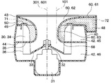
- FIG. 2 is a sectional view taken along line II-II of FIG. 1.
- FIG. 3 is a sectional view taken along line III-III in FIGS. 1 and 2.
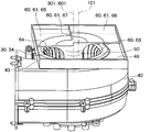
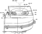
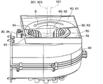
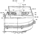
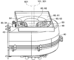
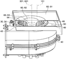
- It is a perspective view of the state which removed the inside and outside air box of the centrifugal type blower concerning a 1st embodiment. It is explanatory drawing for demonstrating a 1st opening part and a 2nd opening part in the centrifugal fan which concerns on 1st Embodiment. It is a perspective view of the state which removed the inside and outside air box of the centrifugal type blower concerning a 2nd embodiment.
- a centrifugal fan concerning a 5th embodiment it is an explanatory view for explaining the 1st opening and the 2nd opening. It is a perspective view of the state which removed the inside and outside air box of the centrifugal type blower concerning a 6th embodiment. In a centrifugal fan concerning a 6th embodiment, it is an explanatory view for explaining the 1st opening and the 2nd opening. It is a perspective view of the state which removed the inside and outside air box of the centrifugal type blower concerning a 7th embodiment. It is explanatory drawing for demonstrating the 1st opening part and the 2nd opening part in the centrifugal fan which concerns on 7th Embodiment.
- the centrifugal blower 1 of the present embodiment is applied to an inside / outside air two-layer flow type vehicle air conditioner.
- the centrifugal blower 1 is a blower capable of simultaneously sucking and blowing out air while distinguishing air inside the vehicle (hereinafter referred to as inside air) and air outside the vehicle (hereinafter referred to as outside air).
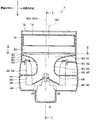
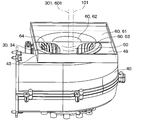
- the centrifugal blower 1 includes an inside / outside air box 10, a filter 20, an impeller 30, a scroll casing 40, a bell mouth 50, a partition wall 44, a separation cylinder 60, and the like.
- the inside / outside air box 10 is arranged above the centrifugal blower 1.
- the inside / outside air box 10 has an outside air introduction port 11, a first inside air introduction port 12 and a second inside air introduction port 13 in this order from the front side of the vehicle. Outside air is introduced into the outside air inlet 11. Inside air is introduced into the first inside air inlet 12 and the second inside air inlet 13.
- a first switching door 14 and a second switching door 15 are provided inside the inside / outside air box 10.
- the first switching door 14 can selectively open and close the outside air introduction port 11 and the first inside air introduction port 12.
- the second switching door 15 can open and close the second inside air introduction port 13.
- the first switching door 14 and the second switching door 15 are, for example, rotary doors.
- the filter 20 is provided below the inside / outside air box 10.
- the filter 20 collects foreign matter contained in the air introduced into the inside / outside air box 10 (that is, outside air and inside air).
- the filter 20 is configured, for example, by folding a filter material for dust removal having a predetermined air permeability into a pleated shape.
- the filter 20 is formed so that the pleats are folded in the direction in which the outside air introduction port 11, the first inside air introduction port 12, and the second inside air introduction port 13 are arranged (for example, the vehicle front-rear direction).
- the filter 20 has fold-shaped folds extending in a direction (eg, the vehicle width direction) orthogonal to the direction in which the outside air inlet 11, the first inside air inlet 12 and the second inside air inlet 13 are arranged. There is.
- the inside / outside air box 10 and the filter 20 are formed in a substantially rectangular outer shape when viewed from above.
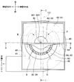
- the impeller 30 is a centrifugal fan that is rotated by the drive of the motor 31.
- the impeller 30 has a main plate 33 fixed to the shaft 32 of the motor 31 and a plurality of blades 34 fixed to the main plate 33.
- the impeller 30 is configured to suck the air that has passed through the filter 20 from one side in the rotation axis direction and blow it out to the outside in the radial direction.
- a blade partition wall 35 is provided between the plurality of blades 34 for partitioning the wind flowing in the axially upper region of the blade 34 and the wind flowing in the axially lower region of the blade 34. There is.
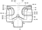
- the scroll casing 40 surrounds the outer side of the impeller 30 in the radial direction.
- the scroll casing 40 has a nose portion 41 on a part of its outer circumference.
- the scroll casing 40 forms an air passage 42 in which the flow passage area gradually increases from the nose portion 41 toward one side in the circumferential direction.
- the air passage 42 is mainly formed between the inner wall of the scroll casing 40 and the trailing edge 36 of the blade 34 of the impeller 30.
- a portion of the ventilation passage 42 having the largest flow passage area communicates with an air conditioning casing (not shown) included in the air conditioning device. Therefore, the air blown from the ventilation passage 42 of the scroll casing 40 is introduced into the air conditioning casing.
- an evaporator for adjusting the temperature and humidity of the air, a heater core, an air mix door, etc. are arranged in the air conditioning casing.
- the conditioned air, the temperature and humidity of which are adjusted in the air conditioning casing, is configured to be blown into the vehicle compartment from the face outlet, the foot outlet, the defroster outlet, and the like.
- An annular bell mouth 50 that forms an air inlet to the impeller 30 is provided on one end surface 49 (hereinafter, referred to as the upper surface 49 of the scroll casing 40) of the scroll casing 40 in the rotation axis direction of the impeller 30. Has been. The air that has passed through the filter 20 is sucked into the impeller 30 from the bell mouth 50.
- a mounting frame 43 for mounting the inside / outside air box 10 and the filter 20 described above is provided on the upper surface 49 of the scroll casing 40. That is, the inside / outside air box 10 and the filter 20 are mounted on the mounting frame 43.
- a partition wall 44 that partitions the ventilation passage 42 into one region in the axial direction of the impeller 30 and the other region in the axial direction of the impeller 30 is provided inside the scroll casing 40.
- the partition wall 44 is provided at a position corresponding to the blade partition wall 35 provided between the blades 34 of the impeller 30.
- a region of the ventilation passage 42 above the partition wall 44 will be referred to as an upper ventilation passage 45, and a region of the ventilation passage 42 below the partition wall 44 will be referred to as a lower ventilation passage 46.
- the separation cylinder 60 is provided from the area between the filter 20 and the impeller 30 to the area inside the impeller 30 in the radial direction.
- the separation cylinder 60 has an air introduction plate 61 provided in a part of a region between the impeller 30 and the filter 20, and an air inlet portion 62 formed in the air introduction plate 61, which is located inside the impeller 30 in the radial direction. It has a tubular portion 63 having a shape that extends through to the outside in the radial direction.
- the air introduction plate 61 has a substantially rectangular outer shape when viewed from above.
- the air introduction plate 61 covers almost half the area of the bell mouth 50.
- the second switching door 15 of the inside / outside air box 10 has the second inside air introduction port 13. Is provided at a position corresponding to the end portion 16 of the second switching door 15 on the filter 20 side when fully opened.
- the position corresponding to the end portion 16 of the second switching door 15 on the filter 20 side can be, for example, the lower side of the end portion 16 of the second switching door 15.
- the air introduction plate 61 and the tubular portion 63 are connected in a funnel shape.
- the tubular portion 63 has a tubular shape in a region inside the impeller 30 in the radial direction.
- the end portion 68 of the tubular portion 63 on the side opposite to the air introduction plate 61 is provided at a position corresponding to the blade partition wall 35 provided between the blades 34 of the impeller 30.
- the position corresponding to the blade partition wall 35 can also be referred to as the radially inner side of the blade partition wall 35.
- the centrifugal blower 1 lowers the air introduced into the inside / outside air box 10 and passing through the predetermined region of the filter 20 from one axial direction of the impeller 30 via the inside of the separation cylinder 60. It is possible to flow to the ventilation path 46. Further, the centrifugal blower 1 can flow the air passing through the other region of the filter 20 from one axial direction of the impeller 30 to the upper ventilation passage 45 via the outside of the separation cylinder 60. That is, the centrifugal blower 1 is a one-sided suction blower.
- the predetermined area of the filter 20 is, for example, an area on the vehicle rear side of the position of the filter 20 where the end 16 of the second switching door 15 abuts.
- the other area of the filter 20 is, for example, an area on the vehicle front side of the position of the filter 20 with which the end portion 16 of the second switching door 15 abuts.
- FIG. 1 shows a state in which the first switching door 14 closes the first inside air introducing port 12 while opening the outside air introducing port 11, and the second switching door 15 opens the second inside air introducing port 13. ..
- the centrifugal blower 1 can simultaneously inhale and blow out while separating the inside air and the outside air.
- the inside air introduced from the second inside air introduction port 13 is formed in the air introduction plate 61 after passing through a region of the filter 20 located substantially directly above the air introduction plate 61. Flowing from the air inlet portion 62 passing through the inside of the tubular portion 63 to the lower ventilation passage 46 via the impeller 30.
- the outside air introduced from the outside air introduction port 11 passes through the region of the filter 20 except a portion directly above the air introduction plate 61, and then the air introduction plate 61 is removed. It flows from the space to the upper ventilation passage 45 through the outside of the tubular portion 63 and the impeller 30.
- the air introduction plate 61 is removed. It flows from the space to the upper ventilation passage 45 through the outside of the tubular portion 63 and the impeller 30.
- arrow B in FIG. 1 and the arrow D in FIG. 3 a part of the air flowing in the region excluding the air introduction plate 61 is radially sucked into the impeller 30 as it is.
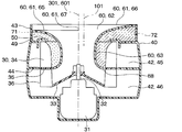
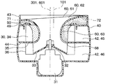
- the flow path 47 on the back side of the separation cylinder 60 is a flow path formed in a gap between the upper surface 49 of the scroll casing 40 and the bell mouth 50, and the air introduction plate 61.
- the outer edge 64 of the air introduction plate 61 is included in the flow path through which air flows from the filter 20 to the upper ventilation passage 45, and is parallel to the rotary shaft 301 of the impeller 30.
- the virtual plane VS is defined.
- the flow passage cross section on the virtual plane VS in the flow passage cross section on the virtual plane VS, the flow passage cross section on the side closer to the nose portion 41 with the separation cylinder 60 interposed therebetween is referred to as a first opening 71,
- the flow path cross section on the side far from the nose portion 41 will be referred to as the second opening 72.
- FIG. 5 for the sake of explanation, although not a cross section, the first opening 71 is hatched with a broken line, and the second opening 72 is hatched with a chain line. This also applies to FIGS. 7, 9, 12, 14, 16, and 18 referred to in second to eighth embodiments described later.
- the center 101 of the inside / outside air box 10 has the second opening with respect to the rotation shaft 301 of the impeller 30 and the center axis 601 of the tubular portion 63 of the separation tube 60. It is at a position displaced to the side of the portion 72. Therefore, the flow passage cross-sectional area of the second opening 72 is configured to be larger than the flow passage cross-sectional area of the first opening 71. Specifically, in the present embodiment, the flow passage cross-sectional area of the region of the second opening 72 on the air introducing plate 61 side of the impeller 30 is the same as that of the first opening 71 on the air introducing plate 61 side of the impeller 30. The area is larger than the flow passage cross-sectional area.
- the ventilation passage 42 formed on the outer side in the radial direction of the impeller 30 is configured such that the flow passage area gradually increases from the nose portion 41 toward one side in the circumferential direction. That is, the distance between the trailing edge 36 of the blade 34 of the impeller 30 and the inner wall of the scroll casing 40 is the smallest in the vicinity of the nose portion 41, and gradually increases from the nose portion 41 toward one side in the circumferential direction. Therefore, the pressure loss of the air flowing from the impeller 30 to the ventilation passage 42 is large in the vicinity of the nose portion 41 and gradually decreases from the nose portion 41 toward one side in the circumferential direction.
- the amount of air sucked into the impeller 30 is small in the vicinity of the nose portion 41 and gradually increases from the nose portion 41 toward one side in the circumferential direction. Therefore, if the flow passage cross-sectional area of the first opening 71 and the flow passage cross-sectional area of the second opening 72 are the same, the amount of air sucked into the impeller 30 via the first opening 71 is The amount is smaller than the amount of air sucked into the impeller 30 via the second opening 72. In that case, the pressure loss of the air passing through the second opening 72 is larger than the pressure loss of the air passing through the first opening 71.
- the center 101 of the inside / outside air box 10 is displaced toward the second opening 72 side with respect to the rotation shaft 301 of the impeller 30 and the center axis 601 of the tubular portion 63 of the separation tube 60.
- the flow passage cross-sectional area of the second opening 72 is configured to be larger than the flow passage cross-sectional area of the first opening 71. Thereby, the pressure loss of the air flowing through the second opening 72 is smaller than that in the case where the flow passage cross-sectional area of the first opening 71 and the flow passage cross-sectional area of the second opening 72 are the same.
- the balance between the pressure loss of the air passing through the first opening 71 and the pressure loss of the air passing through the second opening 72 corresponds to the air volume characteristic sucked into the impeller 30, and the separation cylinder 60
- the amount of air flowing through the flow path 47 on the back side increases. Therefore, the amount of air sucked into the impeller 30 from the flow path 47 on the back side of the separation cylinder 60 increases, and the blowing efficiency of the blower can be improved.
- the center 101 of the inside / outside air box 10 is configured to be displaced toward the second opening 72 side with respect to the rotation shaft 301 of the impeller 30 and the center axis 601 of the tubular portion 63 of the separation tube 60. .. Therefore, the flow passage cross-sectional area of the first opening 71 and the second opening 71 are increased without increasing the size of the impeller 30 in the centrifugal fan 1 in the rotation axis direction (for example, the size in the height direction of the centrifugal fan 1). It is possible to adjust the flow passage cross-sectional area of the portion 72.
- the flow passage cross-sectional areas of the first opening 71 and the second opening 72 are changed without largely changing the configuration of the inside / outside air box 10 and the configuration of the separation tube 60 from the conventional centrifugal blower. It is possible to adjust.
- the conventional centrifugal blower means that the center 101 of the inside / outside air box 10, the rotation shaft 301 of the impeller 30, and the center shaft 601 of the separation cylinder 60 are aligned with each other.
- the lower ventilation passage is passed from the inside / outside air box 10 through the inside of the separation tube 60. It does not affect the flow of air through 46.
- the second to eighth embodiments will be described.
- the second to eighth embodiments are different from the first embodiment in the configuration of the separation cylinder 60 or the inside / outside air box 10, and other aspects are the same as those in the first embodiment. Therefore, the first embodiment Only the parts different from the above will be explained.
- the air introduction plate 61 included in the separation cylinder 60 is located on the first surface 71 side located on the first opening 71 side and on the second opening 72 side. And a step surface 67 that connects the first surface 65 and the second surface 66.
- the second surface 66 is arranged farther from the bell mouth 50 than the first surface 65.
- the center 101 of the inside / outside air box 10 is displaced toward the second opening 72 side with respect to the rotation shaft 301 of the impeller 30 and the center axis 601 of the tubular portion 63 of the separation tube 60. It is in.
- the flow passage cross-sectional area of the region of the second opening 72 closer to the air introduction plate 61 than the impeller 30 has the air introduction from the impeller 30 of the first opening 71. It is configured to be larger than the flow passage cross-sectional area of the region on the plate 61 side. Therefore, the flow passage cross-sectional area of the second opening 72 is configured to be larger than the flow passage cross-sectional area of the first opening 71. Therefore, the second embodiment can also achieve the same operational effects as the first embodiment.
- the portion on the second opening 72 side is farther from the bell mouth 50 than the portion on the first opening 71 side. So that the bell mouth 50 is inclined.
- the center 101 of the inside / outside air box 10 is displaced toward the second opening 72 side with respect to the rotation shaft 301 of the impeller 30 and the center axis 601 of the tubular portion 63 of the separation tube 60. It is in.
- the flow passage cross-sectional area of the region of the second opening 72 on the air introduction plate 61 side of the impeller 30 is such that the air introduction from the impeller 30 of the first opening 71 is large. It is configured to be larger than the flow passage cross-sectional area of the region on the plate 61 side. Therefore, the flow passage cross-sectional area of the second opening 72 is configured to be larger than the flow passage cross-sectional area of the first opening 71. Therefore, also in the third embodiment, the same operational effects as those in the first embodiment and the like can be obtained.
- the air introduction plate 61 included in the separation cylinder 60 is arranged such that the portion on the second opening 72 side is farther from the bell mouth 50 than the portion on the first opening 71 side. , The bell mouth 50 is inclined. Further, in the fourth embodiment, as shown by an arrow S in FIG. 10, a portion of the air introduction plate 61 radially outside the air inlet portion 62 is inclined with respect to the bell mouth 50 in the circumferential direction of the air inlet portion 62.
- the flow passage cross-sectional area of the region of the second opening 72 on the air introduction plate 61 side of the impeller 30 has the air introduction from the impeller 30 of the first opening 71. It is configured to be larger than the flow passage cross-sectional area of the region on the plate 61 side. Therefore, the flow passage cross-sectional area of the second opening 72 is configured to be larger than the flow passage cross-sectional area of the first opening 71. Therefore, the fourth embodiment can also achieve the same operational effects as the first embodiment and the like.
- a portion of the air inlet plate 61 radially outside the air inlet portion 62 is formed in the above-described slope shape, so that the air flowing in the flow passage 47 on the back side of the separation cylinder 60 in the circumferential direction. The pressure loss of can be reduced.
- the radius of curvature R2 of the portion of the connecting portion between the air introduction plate 61 and the tubular portion 63 of the separation tube 60 on the second opening 72 side is: It is formed to be smaller than the radius of curvature R1 of the portion on the first opening 71 side.
- the center 101 of the inside / outside air box 10 is displaced toward the second opening 72 side with respect to the rotation shaft 301 of the impeller 30 and the center axis 601 of the tubular portion 63 of the separation tube 60. It is in.
- the flow passage cross-sectional area of the region of the second opening 72 closer to the air introduction plate 61 than the impeller 30 has the air introduction from the impeller 30 of the first opening 71. It is configured to be larger than the flow passage cross-sectional area of the region on the plate 61 side. Therefore, the flow passage cross-sectional area of the second opening 72 is configured to be larger than the flow passage cross-sectional area of the first opening 71. Therefore, the fifth embodiment can also achieve the same operational effects as the first embodiment and the like.
- the flow passage cross-sectional area of the second opening 72 is configured to be larger than the flow passage cross-sectional area of the first opening 71.
- the flow passage cross-sectional area of the region of the second opening 72 on the air introduction plate 61 side of the impeller 30 is the flow passage cross-sectional area of the region of the first opening 71 on the air introduction plate 61 side of the impeller 30. It is made larger than the cross-sectional area.
- the flow passage cross-sectional area of the region of the second opening 72 radially inside the impeller 30 is also larger than the flow passage cross-sectional area of the region inside the impeller 30 of the first opening 71. .. Therefore, the sixth embodiment can also achieve the same operational effects as those of the first embodiment and the like.
- the inside / outside air box 10 and the air introduction plate 61 are partly located outside the outer edge of the scroll casing 40.
- An arcuate outer flow path 48 is formed in a region radially outside the outer circumference of the scroll casing 40.
- the outer flow path 48 is formed so as to include a region opposite to the air introduction plate 61 with respect to the upper surface 49 of the scroll casing 40 and the bell mouth 50, radially outside the outer periphery of the scroll casing 40. Accordingly, in the seventh embodiment, a part of the air that has passed through the filter 20 flows so as to be sucked into the impeller 30 from the second opening 72 via the outer flow path 48.
- the flow passage cross-sectional area of the second opening 72 is configured to be larger than the flow passage cross-sectional area of the first opening 71. Therefore, the seventh embodiment can also achieve the same effects as the first embodiment and the like.
- the center 101 of the inside / outside air box 10 is located at a position displaced toward the second opening 72 side with respect to the rotation shaft 301 of the impeller 30. Further, in the eighth embodiment, the central axis 601 of the tubular portion 63 of the separation tube 60 is located at a position displaced toward the first opening 71 side with respect to the rotary shaft 301 of the impeller 30.
- the flow passage cross-sectional area of the second opening 72 is larger than the flow passage cross-sectional area of the first opening 71.
- the flow passage cross-sectional area of the region of the second opening 72 on the air introduction plate 61 side of the impeller 30 is the flow passage cross-sectional area of the region of the first opening 71 on the air introduction plate 61 side of the impeller 30. It is made larger than the cross-sectional area.
- the flow passage cross-sectional area of the region of the second opening 72 on the radially inner side of the impeller 30 is also larger than the flow passage cross-sectional area of the region of the first opening 71 on the radially inner side of the impeller 30. .. Therefore, the eighth embodiment can also achieve the same operational effects as the first embodiment and the like.
- the shape, the positional relationship, etc., the shape thereof when referring to the shapes of the components and the like, the positional relationship, etc., unless otherwise explicitly stated and in principle, the shape, the positional relationship, etc., the shape thereof, It is not limited to the positional relationship or the like. That is, in the description of each of the above-described embodiments, terms such as “upper”, “lower”, “left”, “right”, “vehicle front”, and “vehicle rear” are used for convenience in the description of each embodiment. The direction in which the centrifugal blower is installed in a vehicle or the like is not limited.
- the centrifugal blower 1 adjusts the positions of the first switching door 14 and the second switching door 15 of the inside / outside air box 10 so that only the outside air or only the inside air flows through both the upper ventilation passage 45 and the lower ventilation passage 46. It is also possible, or it is possible to allow the air in which the inside air and the outside air are mixed to flow.
- the nose portion 41 and the air conditioning casing are arranged on the right side in the vehicle width direction of the scroll casing 40, but the invention is not limited to this.
- the centrifugal blower 1 may have a configuration in which the nose portion 41 and the air conditioning casing are arranged on the left side of the scroll casing 40 in the vehicle width direction.
- the inside / outside air box 10 has been described as having the outside air introduction port 11, the first inside air introduction port 12, and the second inside air introduction port 13 in this order from the vehicle front side. , But is not limited to this.
- the outside air introduction port 11, the first inside air introduction port 12, and the second inside air introduction port 13 may be arranged in the vehicle width direction, or may be arranged sequentially from the vehicle rear side, or , May be arranged diagonally.
- the one-side suction centrifugal fan applied to the inside / outside air two-layer air-conditioning device is provided with the vehicle interior air and the vehicle exterior air. It is possible to inhale at the same time while classifying.
- This centrifugal blower includes an inside / outside air box, an impeller, a scroll casing, a bell mouth, a partition wall, and a separation cylinder.
- the inside / outside air box has an outside air introduction port for introducing the air outside the vehicle compartment and an inside air introduction port for introducing the air inside the vehicle compartment.
- the impeller rotates by the drive of the motor, sucks the air introduced into the inside / outside air box from one side in the rotation axis direction and blows it out to the outside in the radial direction.
- the scroll casing surrounds the outer side of the impeller in the radial direction, and forms a ventilation passage in which the flow passage area gradually increases from the nose portion provided in a part of the outer periphery toward one side in the circumferential direction.
- a bell mouth that forms an air inlet to the impeller is formed in an annular shape and is provided on one end surface of the scroll casing in the rotational axis direction of the impeller.
- the partition wall partitions the ventilation passage formed on the radially outer side of the impeller into one upper ventilation passage in the axial direction of the impeller and the other lower ventilation passage in the axial direction of the impeller.
- the separation cylinder is an air inlet plate provided in a part of the inner / outer air chamber side of the impeller, and an air inlet portion formed in the air inlet plate that passes through the inner side of the impeller to the outer side in the radial direction. It has a cylindrical portion that is expanded.
- the air flowing from the inside / outside air box to the air introduction plate flows from the air inlet part through the inside of the tubular part to the lower ventilation passage via the impeller, and the air is removed from the inside / outside air box to the area excluding the air introduction plate.
- the flowing air is configured to pass through the outside of the tubular portion and to the upper ventilation path via the impeller.
- the nose portion is sandwiched between the separation cylinders.
- the flow passage cross section on the near side is called a first opening portion
- the flow passage cross section on the side far from the nose portion is called a second opening portion.
- the flow passage cross-sectional area of the second opening is larger than the flow passage cross-sectional area of the first opening.
- the center of the inside / outside air box is located at a position displaced toward the second opening with respect to the rotation axis of the impeller and the center axis of the tubular portion of the separation tube.
- the flow passage cross-sectional area of the region of the second opening portion closer to the air introduction plate than the impeller is configured to be larger than the flow passage cross-sectional area of the region of the first opening portion closer to the air introduction plate.
- the configuration of the inside / outside air box and the configuration of the separation cylinder are significantly changed without increasing the size of the impeller of the centrifugal blower in the rotation axis direction (for example, the height direction of the centrifugal blower). Without this, it is possible to adjust the flow passage cross-sectional areas of the first opening and the second opening.
- the air introduction plate has a first surface located on the side of the first opening and a second surface located on the side of the second opening and located farther from the bell mouth than the first surface. And a stepped surface connecting the first surface and the second surface.
- the air introduction plate is inclined with respect to the bell mouth so that the portion on the second opening side is farther from the bell mouth than the portion on the first opening side.
- the flow passage cross-sectional area of the region of the second opening portion closer to the air introduction plate than the impeller is configured to be larger than the flow passage cross-sectional area of the region of the first opening portion closer to the air introduction plate. Is possible.
- the portion of the air inlet plate radially outside the air inlet portion is formed in a slope shape such that the inclination rate with respect to the bell mouth is constant in the circumferential direction of the air inlet portion.
- the radius of curvature of the portion on the side of the second opening is smaller than the radius of curvature of the portion on the side of the first opening in the connecting portion between the air introduction plate and the tubular portion. ..
- the flow passage cross-sectional area of the region of the second opening portion closer to the air introduction plate than the impeller is configured to be larger than the flow passage cross-sectional area of the region of the first opening portion closer to the air introduction plate. Is possible.
- the central axis of the tubular portion of the separation tube is at a position displaced toward the first opening with respect to the rotation axis of the impeller and the center of the inside / outside air box.
- the flow passage cross-sectional area of the second opening can be made larger than the flow passage cross-sectional area of the first opening. According to this, without increasing the size of the centrifugal fan in the rotation axis direction (for example, the height direction) of the impeller and the direction perpendicular to the rotation axis direction of the impeller (for example, the width direction), It is possible to adjust the flow passage cross-sectional areas of the first opening and the second opening.
- the center of the inside / outside air box is located at a position deviated to the second opening side with respect to the rotation axis of the impeller, and the central axis of the tubular portion of the separation cylinder is the impeller.
- the flow passage cross-sectional area of the second opening can be made larger than the flow passage cross-sectional area of the first opening.
- the outer edges of the inside / outside air box and the air introduction plate are located outside the outer edge of the scroll casing.
- the outer flow passage is formed so as to include a region radially outside the outer circumference of the scroll casing and a region opposite to the air introduction plate with respect to the bell mouth. Then, a part of the air introduced into the inside / outside air box is configured to be sucked into the impeller from the second opening via the outer flow path. Thereby, the flow passage cross-sectional area of the second opening can be made larger than the flow passage cross-sectional area of the first opening.
Landscapes
- Engineering & Computer Science (AREA)
- Mechanical Engineering (AREA)
- General Engineering & Computer Science (AREA)
- Physics & Mathematics (AREA)
- Thermal Sciences (AREA)
- Structures Of Non-Positive Displacement Pumps (AREA)
Priority Applications (2)
| Application Number | Priority Date | Filing Date | Title |
|---|---|---|---|
| CN201980075975.1A CN113056614B (zh) | 2018-11-19 | 2019-10-03 | 离心式送风机 |
| US17/238,679 US11852163B2 (en) | 2018-11-19 | 2021-04-23 | Single suction centrifugal blower |
Applications Claiming Priority (2)
| Application Number | Priority Date | Filing Date | Title |
|---|---|---|---|
| JP2018216355A JP7147499B2 (ja) | 2018-11-19 | 2018-11-19 | 遠心式送風機 |
| JP2018-216355 | 2018-11-19 |
Related Child Applications (1)
| Application Number | Title | Priority Date | Filing Date |
|---|---|---|---|
| US17/238,679 Continuation US11852163B2 (en) | 2018-11-19 | 2021-04-23 | Single suction centrifugal blower |
Publications (1)
| Publication Number | Publication Date |
|---|---|
| WO2020105293A1 true WO2020105293A1 (ja) | 2020-05-28 |
Family
ID=70774155
Family Applications (1)
| Application Number | Title | Priority Date | Filing Date |
|---|---|---|---|
| PCT/JP2019/039151 Ceased WO2020105293A1 (ja) | 2018-11-19 | 2019-10-03 | 遠心式送風機 |
Country Status (4)
| Country | Link |
|---|---|
| US (1) | US11852163B2 (enExample) |
| JP (1) | JP7147499B2 (enExample) |
| CN (1) | CN113056614B (enExample) |
| WO (1) | WO2020105293A1 (enExample) |
Families Citing this family (2)
| Publication number | Priority date | Publication date | Assignee | Title |
|---|---|---|---|---|
| JP7159804B2 (ja) * | 2018-11-19 | 2022-10-25 | 株式会社デンソー | 遠心式送風機 |
| EP4130489A1 (en) * | 2021-08-03 | 2023-02-08 | Bleckmann GmbH & Co. KG | Pressure bushing for a fluid pump and a pump including the pressure bushing |
Citations (2)
| Publication number | Priority date | Publication date | Assignee | Title |
|---|---|---|---|---|
| JP2018035792A (ja) * | 2016-09-02 | 2018-03-08 | 株式会社ヴァレオジャパン | 車両用空調装置のための遠心送風機 |
| WO2018074339A1 (ja) * | 2016-10-18 | 2018-04-26 | 株式会社ヴァレオジャパン | 遠心送風機 |
Family Cites Families (29)
| Publication number | Priority date | Publication date | Assignee | Title |
|---|---|---|---|---|
| JP4022975B2 (ja) * | 1997-04-07 | 2007-12-19 | 株式会社デンソー | 車両用空調装置 |
| FR2788086B1 (fr) | 1998-12-30 | 2001-02-09 | Valeo Climatisation | Dispositif de chauffage, ventilation et/ou climatisation comportant un pulseur d'aspiration |
| JP2001032799A (ja) | 1999-07-22 | 2001-02-06 | Zexel Valeo Climate Control Corp | 送風装置と該送風装置を具備する車両用空調装置 |
| JP2002019445A (ja) | 2000-07-10 | 2002-01-23 | Sanden Corp | 車両用空調装置 |
| JP3653629B2 (ja) | 2001-03-16 | 2005-06-02 | 一文機工株式会社 | 二重管と二管路管との継手管、二重管用ベントキャップ及び二重管用防火ダンパー付きベントキャップ |
| JP3858744B2 (ja) | 2002-04-09 | 2006-12-20 | 株式会社デンソー | 遠心式送風機 |
| JP3843928B2 (ja) | 2002-10-15 | 2006-11-08 | 株式会社デンソー | 遠心式送風機 |
| US20040093885A1 (en) * | 2002-11-11 | 2004-05-20 | Koji Ito | Vehicle air conditioner with main blower and sub-blower |
| US7883312B2 (en) * | 2005-03-31 | 2011-02-08 | Mitsubishi Heavy Industries, Ltd. | Centrifugal blower |
| JP4631941B2 (ja) * | 2008-07-18 | 2011-02-16 | 株式会社デンソー | 遠心式送風機 |
| JP5724827B2 (ja) * | 2011-02-16 | 2015-05-27 | 株式会社デンソー | 空力音低減装置 |
| JP6318854B2 (ja) * | 2013-07-18 | 2018-05-09 | 株式会社デンソー | 車両用空調装置 |
| JP6015607B2 (ja) * | 2013-09-18 | 2016-10-26 | 株式会社デンソー | 車両用空調ユニット |
| FR3014029B1 (fr) | 2013-12-04 | 2015-12-18 | Valeo Systemes Thermiques | Pulseur d'aspiration destine a un dispositif de chauffage, ventilation et/ou climatisation d'un vehicule automobile |
| EP3212942A1 (fr) | 2014-10-30 | 2017-09-06 | Valeo Systemes Thermiques | Ventilateur centrifuge avec séparateurs de flux |
| JP6551173B2 (ja) * | 2015-11-09 | 2019-07-31 | 株式会社デンソー | 遠心送風機 |
| FR3045741B1 (fr) | 2015-12-17 | 2019-04-05 | Valeo Systemes Thermiques | Pulseur d'aspiration destine a un dispositif de chauffage, ventilation et/ou climatisation d'un vehicule automobile et dispositif de chauffage, ventilation et/ou climatisation |
| JP6862290B2 (ja) * | 2016-06-21 | 2021-04-21 | 株式会社ヴァレオジャパン | 車両用空調装置のための遠心送風機 |
| JP6576891B2 (ja) | 2016-09-02 | 2019-09-18 | 株式会社ヴァレオジャパン | 車両用空調装置のための遠心送風機 |
| KR101836694B1 (ko) | 2016-09-12 | 2018-03-08 | 현대자동차주식회사 | 내-외기 분리 유동 제어가 가능한 자동차용 공조 장치 |
| JP6632505B2 (ja) | 2016-10-05 | 2020-01-22 | 株式会社ヴァレオジャパン | 車両用空調ユニット |
| JP6662761B2 (ja) * | 2016-12-06 | 2020-03-11 | 株式会社ヴァレオジャパン | 遠心送風機 |
| JP6768531B2 (ja) | 2017-01-04 | 2020-10-14 | 株式会社ヴァレオジャパン | 遠心送風機 |
| JP2018155151A (ja) * | 2017-03-16 | 2018-10-04 | 株式会社ヴァレオジャパン | 車両用空調装置のための遠心送風機 |
| JP2018178830A (ja) * | 2017-04-11 | 2018-11-15 | 株式会社ヴァレオジャパン | 遠心送風機 |
| JP7091765B2 (ja) | 2018-03-26 | 2022-06-28 | 株式会社デンソー | 遠心式送風機 |
| JP7031427B2 (ja) | 2018-03-26 | 2022-03-08 | 株式会社デンソー | 遠心式送風機 |
| JP7103312B2 (ja) | 2018-07-12 | 2022-07-20 | 株式会社デンソー | 遠心式送風機 |
| JP7059954B2 (ja) | 2018-07-12 | 2022-04-26 | 株式会社デンソー | 遠心式送風機 |
-
2018
- 2018-11-19 JP JP2018216355A patent/JP7147499B2/ja active Active
-
2019
- 2019-10-03 CN CN201980075975.1A patent/CN113056614B/zh active Active
- 2019-10-03 WO PCT/JP2019/039151 patent/WO2020105293A1/ja not_active Ceased
-
2021
- 2021-04-23 US US17/238,679 patent/US11852163B2/en active Active
Patent Citations (2)
| Publication number | Priority date | Publication date | Assignee | Title |
|---|---|---|---|---|
| JP2018035792A (ja) * | 2016-09-02 | 2018-03-08 | 株式会社ヴァレオジャパン | 車両用空調装置のための遠心送風機 |
| WO2018074339A1 (ja) * | 2016-10-18 | 2018-04-26 | 株式会社ヴァレオジャパン | 遠心送風機 |
Also Published As
| Publication number | Publication date |
|---|---|
| JP7147499B2 (ja) | 2022-10-05 |
| CN113056614A (zh) | 2021-06-29 |
| JP2020084818A (ja) | 2020-06-04 |
| CN113056614B (zh) | 2023-06-20 |
| US20210239128A1 (en) | 2021-08-05 |
| US11852163B2 (en) | 2023-12-26 |
Similar Documents
| Publication | Publication Date | Title |
|---|---|---|
| JP3843928B2 (ja) | 遠心式送風機 | |
| JP2019044739A (ja) | 車両用空調装置のための遠心送風機 | |
| JP7200824B2 (ja) | 遠心送風機 | |
| WO2020105293A1 (ja) | 遠心式送風機 | |
| WO2020105292A1 (ja) | 遠心式送風機 | |
| CN114761693B (zh) | 离心送风机 | |
| US20220282735A1 (en) | Blower | |
| JP7070361B2 (ja) | 送風機 | |
| JP7255448B2 (ja) | 送風機 | |
| WO2021187175A1 (ja) | 遠心送風機 | |
| WO2021085086A1 (ja) | 送風機 | |
| WO2021090648A1 (ja) | 送風機 | |
| JP7358946B2 (ja) | 送風機およびフィルタ装置 | |
| WO2020095563A1 (ja) | 遠心送風機 | |
| WO2020162133A1 (ja) | 遠心送風機 |
Legal Events
| Date | Code | Title | Description |
|---|---|---|---|
| 121 | Ep: the epo has been informed by wipo that ep was designated in this application |
Ref document number: 19886605 Country of ref document: EP Kind code of ref document: A1 |
|
| NENP | Non-entry into the national phase |
Ref country code: DE |
|
| 122 | Ep: pct application non-entry in european phase |
Ref document number: 19886605 Country of ref document: EP Kind code of ref document: A1 |