WO2020105268A1 - 姿勢転換装置 - Google Patents
姿勢転換装置Info
- Publication number
- WO2020105268A1 WO2020105268A1 PCT/JP2019/036895 JP2019036895W WO2020105268A1 WO 2020105268 A1 WO2020105268 A1 WO 2020105268A1 JP 2019036895 W JP2019036895 W JP 2019036895W WO 2020105268 A1 WO2020105268 A1 WO 2020105268A1
- Authority
- WO
- WIPO (PCT)
- Prior art keywords
- tire
- pallet
- posture
- pressing
- posture changing
- Prior art date
- Legal status (The legal status is an assumption and is not a legal conclusion. Google has not performed a legal analysis and makes no representation as to the accuracy of the status listed.)
- Ceased
Links
Images





Classifications
-
- B—PERFORMING OPERATIONS; TRANSPORTING
- B65—CONVEYING; PACKING; STORING; HANDLING THIN OR FILAMENTARY MATERIAL
- B65G—TRANSPORT OR STORAGE DEVICES, e.g. CONVEYORS FOR LOADING OR TIPPING, SHOP CONVEYOR SYSTEMS OR PNEUMATIC TUBE CONVEYORS
- B65G7/00—Devices for assisting manual moving or tilting heavy loads
- B65G7/02—Devices adapted to be interposed between loads and the ground or floor, e.g. crowbars with means for assisting conveyance of loads
- B65G7/08—Devices adapted to be interposed between loads and the ground or floor, e.g. crowbars with means for assisting conveyance of loads for tilting the loads
-
- B—PERFORMING OPERATIONS; TRANSPORTING
- B65—CONVEYING; PACKING; STORING; HANDLING THIN OR FILAMENTARY MATERIAL
- B65G—TRANSPORT OR STORAGE DEVICES, e.g. CONVEYORS FOR LOADING OR TIPPING, SHOP CONVEYOR SYSTEMS OR PNEUMATIC TUBE CONVEYORS
- B65G57/00—Stacking of articles
- B65G57/28—Stacking of articles by assembling the articles and tilting the assembled articles to a stacked position
-
- B—PERFORMING OPERATIONS; TRANSPORTING
- B65—CONVEYING; PACKING; STORING; HANDLING THIN OR FILAMENTARY MATERIAL
- B65G—TRANSPORT OR STORAGE DEVICES, e.g. CONVEYORS FOR LOADING OR TIPPING, SHOP CONVEYOR SYSTEMS OR PNEUMATIC TUBE CONVEYORS
- B65G57/00—Stacking of articles
- B65G57/02—Stacking of articles by adding to the top of the stack
- B65G57/16—Stacking of articles of particular shape
- B65G57/20—Stacking of articles of particular shape three-dimensional [3D], e.g. cubiform or cylindrical
-
- B—PERFORMING OPERATIONS; TRANSPORTING
- B65—CONVEYING; PACKING; STORING; HANDLING THIN OR FILAMENTARY MATERIAL
- B65G—TRANSPORT OR STORAGE DEVICES, e.g. CONVEYORS FOR LOADING OR TIPPING, SHOP CONVEYOR SYSTEMS OR PNEUMATIC TUBE CONVEYORS
- B65G2201/00—Indexing codes relating to handling devices, e.g. conveyors, characterised by the type of product or load being conveyed or handled
- B65G2201/02—Articles
- B65G2201/0273—Tires
-
- B—PERFORMING OPERATIONS; TRANSPORTING
- B65—CONVEYING; PACKING; STORING; HANDLING THIN OR FILAMENTARY MATERIAL
- B65G—TRANSPORT OR STORAGE DEVICES, e.g. CONVEYORS FOR LOADING OR TIPPING, SHOP CONVEYOR SYSTEMS OR PNEUMATIC TUBE CONVEYORS
- B65G2814/00—Indexing codes relating to loading or unloading articles or bulk materials
- B65G2814/03—Loading or unloading means
- B65G2814/0301—General arrangements
- B65G2814/0304—Stacking devices
Definitions
- the present invention relates to a posture changing device that changes the posture of a pallet that holds tires between a vertical posture that holds stacked tires and a horizontal posture that holds side-by-side tires.
- Patent Document 1 describes a device that automatically stacks tires in a stacked state side by side and mounts them on a pallet.
- the posture of the tire is changed between the side-by-side state and the stacked state.
- the tires may be misaligned and overlapped.
- the holding device of the gantry crane cannot be inserted into the tires, so that it is necessary to maintain the stacked state without any deviation.
- the present invention has been made in view of the above problems, and an object of the present invention is to provide a posture change device that can change the posture of a tire in a stacked state without shifting the tires in a side-by-side state, and can also change the posture in the opposite direction.
- a posture changing device which is one of the present invention is a vertical posture pallet for holding a tire group in a laterally arranged state in which a plurality of vertically oriented tires are arranged in a vertical posture together with the tire group.
- a posture changing device capable of changing the posture of the held pallet by rotating the base, the base holding the pallet, and the tire held on the pallet.
- a standing device that is located at one end of the group and stands up the inclined tire that is the tilted tire toward the other end, and restricts the movement of the tire by contacting at least a part of the peripheral surface of the tire group.
- a regulation device for controlling.
- the upright device a pressing member that applies a pressing force toward the other end of the tire group to the inclined tire, a retracting device that retracts the pressing member between the inclined tire and the pallet, advance A moving device that generates the pressing force toward the other end of the inclined tire with respect to the pressing member in the state may be provided.
- the pressing member may include a roller unit that rotates in contact with the inclined tire.
- the friction between the tire and the pressing member can be reduced, and the tire can be easily raised.
- the standing device may be attached to the base and move along with the change of posture of the pallet. Further, the regulating device may be attached to the base and move along with the change of posture of the pallet.
- the posture can be changed between the stacked state and the side-by-side state of a plurality of tires while suppressing the shift between the tires.
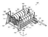
- FIG. 1 is a perspective view showing a posture changing device according to the first embodiment.
- FIG. 2 is a perspective view showing the posture changing device for holding the tires in the horizontally arranged state in which the pallets are held according to the first embodiment.
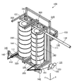
- FIG. 3 is a perspective view showing a posture changing device for holding the stacked tires of the pallet according to the first embodiment.
- FIG. 4 is a perspective view showing the pallet according to the first embodiment.
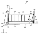
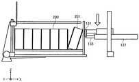
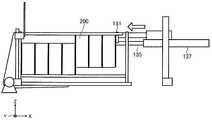
- FIG. 5 is a side view showing a state of the posture changing device before the tilted tire according to the first embodiment is raised.
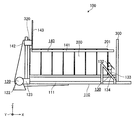
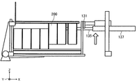
- FIG. 6 is a side view showing a state of the posture changing device after the tilted tire according to the first embodiment is raised.
- FIG. 7 is a side view showing the posture changing device according to the second embodiment.
- FIG. 1 is a perspective view showing a posture changing device according to the first embodiment.
- FIG. 2 is a perspective view showing the posture changing device for holding the tires in the horizontally arranged state in which the pallets are held according to the
- FIG. 8 is a flowchart showing a flow of operations of the posture changing device according to the second embodiment.
- FIG. 9 is a side view No. 1 showing a flow of the operation of the posture changing device according to the second embodiment.
- FIG. 10 is a second side view showing the flow of the operation of the posture changing device according to the second embodiment.
- FIG. 11 is a third side view showing a flow of the operation of the posture changing device according to the second embodiment.
- FIG. 12 is a fourth side view showing the flow of the operation of the posture changing device according to the second embodiment.
- FIG. 13 is a fifth side view showing a flow of the operation of the posture changing device according to the second embodiment.
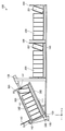
- FIG. 14 is a side view showing the posture changing device according to the third embodiment.
- FIG. 15 is a flowchart showing a flow of operations of the posture changing device according to the third embodiment.
- FIG. 1 is a perspective view showing a posture changing device according to the first embodiment.
- FIG. 2 is a perspective view showing a posture changing device for holding tires in a side-by-side state in which pallets are held.
- FIG. 3 is a perspective view showing a posture changing device for holding tires in a stacked state in which pallets are held.
- the posture changing apparatus 100 as shown in FIG. 2, has a pallet 300 holding a tire group in a laterally arranged state in which a plurality of vertically oriented tires 200 are arranged in the vertical posture shown in FIG. 3 together with the tire group.
- FIG. 2 is a device for placing a pallet 300, which holds a tire group in a stacked state in which a plurality of horizontally oriented tires 200 are stacked, together with the tire group in the lateral position shown in FIG.
- the device 130 and the regulation device 140 are provided.
- the tire 200 that is switched between the stacked state and the side-by-side state by the posture changing device 100 is, for example, the tire 200 used for a medium-sized vehicle such as an automobile or a large vehicle such as a truck or a bus. It is not particularly limited to those used for agricultural machines and construction machines.
- the tire group in the first embodiment, the claims and the like means a group of a plurality of tires 200 held by the pallet 300.
- the tire 200 positioned at the end of the tire group in the side-by-side state and inclined not in the vertical direction but leaning against the pallet 300 is referred to as an inclined tire 201.
- the tilted tire 201 is one of the tires 200, and is not the tilted tire 201 when the tire is tilted and becomes vertical.
- the pallet 300 which is the posture change target of the posture changing device 100, includes a horizontal placing portion 310 on which a plurality of tires 200 are horizontally placed in the horizontal posture shown in FIG. 4, and a vertical posture (see FIG. 3).
- a vertical mounting portion 320 on which the tires 200 in a stacked state are mounted is provided.
- the pallet 300 includes the frame 330 in which the vertical placement section 320 is arranged so as to project in the direction intersecting the horizontal placement section 310 at the end of the horizontal placement section 310.
- the pallet 300 is provided with a stopper 340 on the opposite side of the vertical placement section 320 to the horizontal placement section 310 so as to face the vertical placement section 320 and to prevent the inclined tire 201 from falling.
- the pallet 300 includes columnar spacers 350 extending in the protruding direction of the vertical mounting portion 320 (Z-axis direction in FIG. 4).
- the spacers 350 are attached to the four corners of the rectangular frame 330, respectively, and by connecting the upper and lower ends of the spacers 350 of the two pallets 300, respectively, the pallet 300 in the horizontal posture can be held in a state where the tire group is held. It has a stacking function.
- the pallet 300 has a structure capable of receiving stacked tire groups conveyed by a crane such as a gantry crane and passing the held tire groups to the crane in a vertical posture.
- the stopper 340 has a shape that supports the tire 200 such that the stopper 340 does not interfere with the hole (the hole in which the wheel is attached) of the held tire 200, for example, at least the side surface of the tire 200 having a U shape or a V shape.
- the tire 200 has a shape capable of abutting at a plurality of positions, and has a gap on the side opposite to the lateral mounting portion 310 with respect to the tire 200, through which a chuck can pass.
- the stopper 340 is arranged in the frame 330 so as not to interfere with the chuck of the crane which is inserted into the hole of the tire 200 and holds the tire group from the inside when the tire group is conveyed using the crane.
- the pallet 300 can hold tires 200 having different diameters, for example, a tire 200 having a diameter that is about 1.5 times larger than the smallest diameter tire 200 that can be held. Further, the pallet 300 is provided with a connecting portion (not shown) for connecting to another pallet 300, and a plurality of pallets 300 such as the two pallets 300 can be used as one pallet.
- the posture changing device 100 can change the postures of the two connected pallets 300 at once. The posture changing device 100 may change the posture of one pallet 300, or may change the postures of three or more pallets 300 at one time.
- the base 110 is a structural member that holds the pallet 300, holds the pallet 300 in a horizontal posture, keeps holding the pallet 300 even during a posture change to a vertical posture, and vice versa. Can also hold the pallet 300.
- the base 110 has a structure in which two L-shaped holding members 111 arranged along the horizontal loading portion 310 and the vertical loading portion 320 of the pallet 300 are connected in an opposed state. There is. Further, the two linked pallets 300 can be held while the tire group is held, even during posture change.
- the base 110 also has a structure capable of transferring the pallet 300 in the horizontal position to a transfer device (not shown) arranged below the base 110.
- the holding member 111 of the base 110 can pass between the rollers of a roller conveyor that is a transfer device, and the pallet 300 that is being held can be placed on the roller conveyor.
- the roller conveyor can carry the placed horizontal pallet 300.
- the horizontal pallet 300 conveyed to the base 110 by the roller conveyor can be held on the base 110 to change its attitude to the vertical posture.
- the conversion drive device 120 rotates the base 110 around a predetermined rotation axis (a rotation axis parallel to the Y axis in the drawing) to change the posture of the held pallet 300 from a horizontal posture to a vertical posture, or vice versa. It is a device that can be converted to.
- the shaft 121 arranged near the outside of the corner of the holding member 111 of the base 110 and fixed to the base 110, and the shaft 121 rotatably held and fixed to the floor or the like.
- the posture changing device 100 is not limited to being driven by a motor, but may be one in which the base 110 is rotated by an actuator such as an air cylinder.
- the upright device 130 is located at one end of the tire group in the side-by-side arrangement as shown in FIG. 5, and inclines the inclined tire 201, which is the inclining tire 200, toward the vertical mounting portion 320 side which is the other end. Device.
- the specific configuration of the upright device 130 is not particularly limited, in the case of the first embodiment, the upright device 130 includes the inclinations included in the two tire groups held by the two connected pallets 300, respectively.
- the tire 201 is a device that can stand up at the same time, and includes a pressing member 131, a retracting device 132, and a moving device 133.
- the standing device 130 is attached to the base 110 and moves along with the change of the posture of the pallet 300 by the change driving device 120.
- the upright device 130 can also move together with the base 110 while keeping the tilted tire 201 raised.
- the pressing member 131 is a member that applies a pressing force to the inclined tire 201 toward the other end of the tire group.
- the specific shape of the pressing member 131 is not particularly limited, in the case of the first embodiment, the pressing member 131 has a rod shape as a whole, and is coaxially arranged on the shaft body and the outer periphery of the shaft body. , A roller portion that contacts the inclined tire 201 and rotates around the axis of the shaft body.
- the roller portion is a resin pipe.
- the roller portion may be arranged over substantially the entire length of the pressing member 131, or a plurality of roller portions may be arranged intermittently along the pressing member 131. As described above, by providing the pressing member 131 with the roller portion, it is possible to reduce friction between the surface of the inclined tire 201 and the pressing member 131 that occur when the inclined tire 201 is raised.
- the pressing member 131 extends along the rotation axis (Y-axis direction in the drawing) of the base 110 and is arranged on each of the two pallets 300 held by the base 110. It has a length such that it overlaps with the two tire groups, and has strength (rigidity) that allows the inclined tires 201 included in the two tire groups to stand up at the same time.
- the pressing member 131 may be a single member or may be a member that expands and contracts by being divided into a plurality of members.
- the pressing member 131 having a telescopic structure can be exemplified.
- the retracting device 132 retracts the pressing member 131 between the inclined tire 201 and the pallet 300, specifically between the inclined tire 201 and the stopper 340 of the pallet 300, in the direction along the rotation axis of the base 110.
- the retracting device 132 moves the pressing member 131 to the position where the tip of the pressing member 131 does not contact the nearest pallet 300 by the air cylinder until the pressing member 131 overlaps the two tire groups. It is possible to advance with a stroke and vice versa with one stroke.
- the driving means of the retracting device 132 is not limited to the air cylinder, and may be a device realized by combining a linear motion motor, a rotary motor and a mechanical component such as a gear.
- the moving device 133 is a device that generates a pressing force for the pushing member 131 in the advanced state toward the other end of the inclined tire 201.
- the moving device 133 moves the pressing member 131 in parallel with the retracting device 132.
- a rail 134 (see FIGS. 5 and 6) arranged at a predetermined angle with respect to the extending direction (X-axis direction in the drawing) of the horizontal mounting portion 310 of the pallet 300 held on the base 110. )
- a retractable device 132 is provided, and the retractable device 132 slidably mounted on the rail 134 is driven by an air cylinder along the rail 134.
- the air pressure to be put into the air cylinder when moving the pressing member 131 together with the retracting device 132 in the direction of raising the tilted tire 201 can be adjusted by a regulator, and by suppressing the pressure, the tilted tires 201 having different diameters are also commonly used. It becomes possible to stand up.
- the direction in which the moving device 133 moves the pressing member 131 is not limited to the straight line.
- the pushing member 131 in the advanced state may be rotated about an axis parallel or substantially parallel to the rotation axis of the base 110.
- the driving means of the moving device 133 is not limited to the air cylinder, and may be a device realized by combining a linear motion motor, a rotation motor and mechanical parts such as gears. That is, the locus of the pressing member 131 when the inclined tire 201 is raised may be not only linear, but also curved or bent.
- the pallet 300 can hold the final position of the trajectory of the pressing member 131, that is, the position of the pressing member 131 in the state where the inclined tire 201 becomes the vertically oriented tire 200.
- the vicinity of the top of the tire 200 having a minimum diameter is preferable.
- the depressed pressing member 131 is advanced to the inner corner portion configured by the horizontal mounting portion 310 and the stopper 340. This increases the possibility that the pressing member 131 can be advanced without interfering with the inclined tire 201 regardless of the diameter of the inclined tire 201 leaning against the stopper 340.
- the restriction device 140 is a device that contacts at least a part of the peripheral surface of the tire 200 held by the posture changing device 100 to restrict the movement of each tire 200 in the tire group.
- the specific configuration of the restricting device 140 is not particularly limited, in the case of the first embodiment, the restricting device 140 includes the contact member 141 and a separating member that separates the contact member 141 from and contact the tire group.
- the contact device 142 and the arm member 143 that connects the contact member 141 and the contact / disconnection device 142 are provided.
- the regulation device 140 is attached to the base 110, and moves together with the posture change of the pallet 300 by the conversion drive device 120.
- the restricting device 140 can also move together with the base 110 while being in contact with the peripheral surface of the tire group.
- two tire groups are respectively held on the base 110 via two pallets 300, and the posture changing apparatus 100 controls the movement of the tires 200 of each tire group to be two. It is provided with one regulation device 140. Further, the two restricting devices 140 are configured to be plane-symmetrical including the direction of operation.
- the contact member 141 is a long member that contacts the peripheral surface of the tire group or applies a pressing force toward the lateral mounting portion 310 to the tire group.
- the specific shape of the contact member 141 is not particularly limited, but in the case of the first embodiment, the contact member 141 is a round bar.
- the abutting member 141 extends along the extending direction of the horizontal mounting portion 310 of the pallet 300 held by the base 110, and has a length about the axial length of the tire group that can be held by the pallet 300. I have it.
- the contacting / separating device 142 rotates the contacting member 141 in an arc shape around the rotation axis that is separated from the contacting member 141 by a predetermined distance along the extending direction of the contacting member 141.
- the separating / connecting device 142 includes a speed reducer and a rotary motor, and transmits the rotation of the rotary motor to the contact member 141 via the speed reducer and the arm member 143.
- the contacting / separating device 142 maintains the contact member 141 in contact with the peripheral surface of the tire group or contacts the peripheral surface of the tire group even when the diameters of the tires 200 forming the tire group are different within a predetermined range.
- the member 141 can be kept pressed. Even when the attitude of the pallet 300 that holds the tire group is being changed, the contacting / separating device 142 does not contact the peripheral surface of the tire group or press the peripheral surface of the tire group with the contact member 141. You can continue to maintain.
- the direction in which the separating / connecting device 142 moves the contact member 141 is not limited to the rotation and swing.
- the contact member 141 may be linearly moved toward the peripheral surface of the tire group.
- the drive means of the separation / contact device 142 is not limited to the rotary motor, and may be a device realized by a linear motion motor, an air cylinder, or the like.
- the arm member 143 can adopt an arbitrary shape such as a curved shape or a linear shape.
- the obstacle is formed by bending the arm member 143 of the first embodiment. While avoiding the above, it is possible to regulate the positional deviation between the tires 200.
- the posture changing device 100 when the inclined tire 201 is located at the end of the tire group in the side-by-side arrangement, the inclined tire 201 is erected before the posture of the pallet 300 is changed to the vertical posture. As a result, it is possible to prevent the position of the tire 200 from shifting during the posture change and after the posture change, and to prevent the tire 200 from dropping. Further, even after the inclined tire 201 has been raised, by continuing to apply a pressing force from the end of the tire group toward the vertical mounting portion 320 by the standing device 130, it is possible to further suppress the maintenance deviation and the fall of the tire 200. it can.
- the chuck attached to the crane can be easily inserted into the holes of the tires, and the tires 200 can be displaced by the chucks. It is possible to improve the efficiency of the tire group unloading work by avoiding a problem such as being unable to insert the tire into the tire.
- the inclination tire 201 is raised by using the standing device 130, It is possible to avoid a situation where the tire 201 is stored.
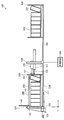
- FIG. 7 is a side view showing the posture changing device according to the second embodiment.
- the posture changing device 100 is a device for changing the pallet 300 holding the plurality of tires 200 from a horizontal posture to a vertical posture, like the first embodiment, and includes a base 110 and The drive device 120, the standing device 130, and the regulation device 140 are provided.
- the posture changing device 100 further includes a control device 150 and a carrying device 160.
- the erection device 130 is a device that is located at one end of the tire group as in the first embodiment and erects the inclined tire 201 toward the vertical mounting portion 320 side.
- a pressing member 131, a retracting device 137, a pressing device 138, and an elevating device 139 are provided.
- the insertion member 135 is a member that is inserted into at least the hole of the inclined tire 201.
- the shape of the insertion member 135 is not particularly limited, but a shape such as a round bar or a cylinder that does not damage the inner circumference of the tire 200 when the tire 200 is lifted is preferable.
- the diameter is set so that it can be inserted into the holes of the tires 200 having different diameters which are successively conveyed to the posture changing apparatus 100.
- the length is set so that a plurality (for example, three) of tires 200 can be lifted.
- the insertion member 135 is set to have a rigidity that can lift the plurality of tires 200 in a cantilever state.
- the pressing member 131 is a member that comes into contact with the end surface of one end of the inclined tire 201. In the case of the second embodiment, the pressing member 131 presses the tire 200 straight from the outside of one end of the tire 200 in the direction in which the tires 200 are arranged.
- the shape of the pressing member 131 is not particularly limited, but since it is a member that comes into contact with the end surfaces of the tires 200 having a plurality of diameters as described above, it does not contact any end surface of the tires 200 having a plurality of diameters.
- a plate-shaped member having a contactable area area of YZ plane in the figure) is desirable.
- the pressing member 131 may include a roller that rotates about an axis that extends parallel to the end surface of the tire 200 in the horizontal plane.
- the withdrawal device 137 is a device for inserting / removing the insertion member 135 into / from the inclined tire 201.
- the retracting device 137 causes the insertion member 135 to advance to the position of the third tire 200 from the tire 200 where the tip of the insertion member 135 is the closest by the air cylinder, and changes the posture of the pallet 300. In doing so, the insertion member 135 can be retracted to a position where it does not interfere with the pallet 300 or the like.
- the pressing device 138 is a device that presses the upper portion of the tire 200, which is the inclined tire 201, toward the other end (the negative direction of the X axis in the drawing) by the pressing member 131 to adjust the position of the tire 200.
- the type of the pressing device 138 is not particularly limited, but in the case of the second embodiment, an air cylinder is used as in the retracting device 137.
- the insertion member 135 and the pressing member 131 are described as separate bodies, and the retractable device 137 and the pressing device 138 are used to operate independently, but the pressing member 131 is A flange-shaped member that protrudes outward from the outer peripheral surface of the insertion member 135 and is fixed to the insertion member 135 may be used.
- the device that causes the pressing member 131 to generate a pressing force to raise the inclined tire 201 is the leaving device 137, and the pressing device 138 is realized by the leaving device 137.
- the elevating device 139 is a device that elevates and lowers the insertion member 135, the pressing member 131, the retracting device 137, and the pressing device 138.
- the lifting device 139 has the power to lift the plurality of tires 200 through which the insertion member 135 is inserted at one time.
- the type of the elevating device 139 is not particularly limited, but in the case of the second embodiment, an elevating mechanism that combines a chain and a pulley is provided, and a device that drives the elevating mechanism by a motor is adopted.
- the elevating device 139 causes the elevating device 139 not to be inserted into the tires 200, the pressing member 131, and the retracting member.
- the device 137 and the pressing device 138 can be raised to above the region where the pallet 300 on which the tire 200 is placed passes.
- the transfer device 160 is a device that transfers the pallet 300 along the direction in which the tires 200 are arranged side by side (the X-axis direction in the drawing) to the position where the posture changing device 100 is arranged.
- the type of the carrier device 160 is not particularly limited, but in the case of the second embodiment, a conveyor is adopted.
- the control device 150 is a so-called computer that controls the retracting device 137, the pressing device 138, and the elevating device 139 to raise the inclined tire 201.
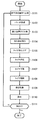
- FIG. 8 is a flowchart showing a flow of operations of the posture changing device 100 according to the second embodiment.
- the control device 150 controls the insertion member 135, the pressing member 131, the retracting device 137, and the pressing device 138 on which the tire 200 is placed.
- the elevating device 139 is controlled so as to ascend to the upper side of the area where 300 passes (S101).
- the transfer device 160 transfers the waiting pallet 300 to the lower position such as the insertion member 135 and transfers it to the posture changing position (S102).
- the control of the transport device 160 may be performed by the control device 150.
- control device 150 moves the elevating device 139 so that the insertion member 135 and the like are lowered to a position where the insertion member 135 can be inserted into the hole of the tire 200, as shown in FIG. Control (S103).
- control device 150 controls the retracting device 137 to insert the insertion member 135 into the holes of the plurality of tires 200 as shown in FIG. 10 (S104).
- control device 150 controls the lifting device 139 to lift the tire 200 as shown in FIG. 11 (S105). Lifting is performed until the tire 200 does not contact the pallet 300.
- control device 150 controls the pressing device 138 so as to press the tire 200 lifted by the pressing member 131 against the tire 200 not lifted (S106).
- control device 150 controls the elevating device 139 to lower the tire 200 until the lifted tire 200 is placed on the pallet 300 again (S107). After processing, the insertion member 135 and the pressing member 131 are retracted.
- the tire 200 is regulated by the regulation device 140 (S108), and the posture of the pallet 300 is changed to stand up in the regulated state to bring the tire 200 into a stacked state (S109).
- the tires 200 and the pallet 300 are carried out using a crane or the like (S110).
- the inclined tire 201 can be oriented vertically without generating strong friction.
- the lifting device 139 that lifts the inclined tire 201, the insertion member 135, the pressing member 131, the pressing device 138, and the retracting device 137 are lifted up to the upper side of the passage area of the pallet 300, so that the posture is changed.
- the pallet 300 to be converted can be easily transported to the posture changing position.
- FIG. 14 is a side view showing the posture changing device according to the third embodiment.
- the posture changing device 100 is a device for changing the pallet 300 holding a plurality of tires 200 from a horizontal posture to a vertical posture, like the first and second embodiments, and includes a base 110.
- the conversion drive device 120, the standing device 130, and the regulation device 140 are provided.
- the posture changing device 100 further includes a carrying device 160.
- the standing device 130 is a device that is located at one end of the tire group in an oblique posture and that stands up the inclined tire 201 toward the vertical mounting portion 320 side.
- the standing device 130 includes a pressing member 131, a pressing device 138, and a conveying device 160.
- the pressing member 131 applies a pressing force toward the other end of the tire group to the inclined tire 201 arranged on the pallet 300 in the oblique posture (see FIG. 14) between the horizontal posture and the vertical posture by the conversion drive device 120. It is a member. Also in the case of the third embodiment, the pressing member 131 presses the tire 200 straight from the outside of one end of the tire 200 in the direction in which the tires 200 are arranged. However, since the tire group has an oblique posture, the pressing member 131 is arranged so as to be perpendicular to the direction in which the tires 200 in the oblique posture are arranged.
- the pressing member 131 is provided with a swinging mechanism capable of swinging up and down at the connecting portion with the pressing device 138, and the pressing member 131 may not be arranged perpendicular to the direction in which the tires 200 are arranged.
- the pressing device 138 presses the inclined tire 201, which is arranged at one end of the tire group in an oblique posture, toward the other end by the pressing member 131.
- the pressing device 138 employs an air cylinder that causes the pressing member 131 to move in and out along the arrangement direction of the tire groups that are inclined by the conversion drive device 120.
- the pressing member 131 and the pressing member 131 are fixedly arranged above the passage area of the pallet 300 by the transfer device 160.
- the pressing device 138 is arranged on the extension line of the line of the tires 200 that are inclined by the conversion driving device 120.
- the lifting angle ⁇ of the tire group by the conversion drive device 120 is equal to or greater than the angle at which the pallet 300 having the tires 200 mounted below the pressing member 131 can pass, and is preferably less than 45 °. This is because if the tire group including the tilted tire 201 is tilted at 45 ° or more, the tilted tire 201 may unintentionally move. In the case of the third embodiment, the lifting angle ⁇ is set to 25 °.
- FIG. 15 is a flowchart showing a flow of operations of the posture changing device 100 according to the third embodiment.
- the carrier device 160 passes the pallet 300 on standby to the lower side of the pressing device 138 and carries the pallet 300 to the posture changing position (S201).
- the control of the transport device 160 may be performed by the control device 150 (not shown in the third embodiment).
- the other pallets 300 are also sequentially transported.
- the conversion drive device 120 is controlled by the control device 150, and as shown in FIG. 14, the pressing direction of the pressing device 138 and the arranging direction of the tires 200 are diagonally aligned.
- the pallet 300 is rotated to the posture (S202).
- the pressing device 138 presses the pressing member 131 against the inclined tire 201 to stand up in the same posture as the other tires 200 (S203).
- the tire 200 is regulated by the regulation device 140 (S204), and the pressing device 138 retracts the pressing member 131 to a predetermined position that does not interfere with the pallet 300 or the like (S205).
- the timing of the regulation and the backward movement may be the same, or either one may be earlier.
- the conversion drive device 120 rotates the pallet 300 again to stand up while the regulation device 140 regulates the tire group, and puts the tires 200 in a stacked state (S206).
- the standby pallet 300 can be arranged in the vicinity of the holding member 110 without interfering with the pressing member 131 and the pressing device 138. Therefore, as compared with the second embodiment. Thus, the pallet 300 can be efficiently sent to the posture changing position.
- the posture changing device 100 does not include the retracting device 137 and does not include the elevating device 139, the tilted tire 201 can be raised with a simple configuration.
- the present invention is not limited to the above embodiment.
- another embodiment realized by arbitrarily combining the constituent elements described in this specification or excluding some of the constituent elements may be an embodiment of the present invention.
- the present invention also includes modified examples obtained by applying various modifications that the person skilled in the art can think of to the above-described embodiment without departing from the gist of the present invention, that is, the scope of the wording described in the claims. Be done.
- the standing device 130 may be operated only when it is determined that the tilted tire 201 exists based on the information from the sensor that detects the presence or absence of the tilted tire 201 and the image information of the end portion of the tire group. ..
- the posture changing device 100 in which the two pallets 300 are connected to change the posture together with the two tire groups has been described, but the posture changing device 100 changes the posture of one pallet 300.
- the pallet 300 may be one that changes the posture of three or more pallets 300.
- the postures of different types of pallets 300 may be changed at the same time within an allowable range.
- the posture changing device 100 may change the posture of the pallet 300 even if the tire groups having different diameters are held.
- the inclined tires 201 of the two tire groups are respectively raised using the single pressing member 131, but the posture changing device 100 is provided with the two raising devices 130 and the respective raising devices are provided. 130 may raise the inclined tire 201 of each tire group.
- the tilted tire 201 may be stood upright by the standing device 130 after the tire group is placed in an oblique posture.
- the present invention can be used in a tire manufacturing factory, a tire storage warehouse, a tire distribution center, and the like.
- posture changing device 110 base 111 holding member 120 conversion driving device 121 shaft 122 bearing 123 drive source 130 standing device 131 pressing member 132 retracting device 133 moving device 134 rail 140 regulating device 141 abutting member 142 separating / connecting device 143 arm member 200 tire 201 inclined tire 300 pallet 310 horizontal mounting portion 320 vertical mounting portion 330 frame 340 stopper 350 spacer
Landscapes
- Engineering & Computer Science (AREA)
- Mechanical Engineering (AREA)
- Stacking Of Articles And Auxiliary Devices (AREA)
- Attitude Control For Articles On Conveyors (AREA)
- Tyre Moulding (AREA)
- Massaging Devices (AREA)
- Threshing Machine Elements (AREA)
- De-Stacking Of Articles (AREA)
Abstract
Description
図1は、実施の形態1に係る姿勢転換装置を示す斜視図である。図2は、パレットの保持された横並び状態のタイヤを保持する姿勢転換装置を示す斜視図である。図3は、パレットの保持された段積み状態のタイヤを保持する姿勢転換装置を示す斜視図である。姿勢転換装置100は、図2に示すように、縦向きの複数のタイヤ200が並べられた横並び状態のタイヤ群を保持するパレット300をタイヤ群と共に図3に示す縦姿勢にし、また図3に示す横向きの複数のタイヤ200が積み重ねられた段積み状態でタイヤ群を保持するパレット300をタイヤ群と共に図2に示す横姿勢にする装置であり、基台110と、転換駆動装置120と、起立装置130と、規制装置140とを備えている。
続いて、姿勢転換装置100の他の実施の形態について説明する。なお、前記実施の形態1と同様の作用や機能、同様の形状や機構や構造を有するもの(部分)には同じ符号を付して説明を省略する場合がある。また、以下では実施の形態1と異なる点を中心に説明し、同じ内容については説明を省略する場合がある。
続いて、姿勢転換装置100の他の実施の形態について説明する。なお、前記実施の形態1、2と同様の作用や機能、同様の形状や機構や構造を有するもの(部分)には同じ符号を付して説明を省略する場合がある。また、以下では実施の形態1、2と異なる点を中心に説明し、同じ内容については説明を省略する場合がある。
110 基台
111 保持部材
120 転換駆動装置
121 軸体
122 軸受
123 駆動源
130 起立装置
131 押圧部材
132 出没装置
133 移動装置
134 レール
140 規制装置
141 当接部材
142 離接装置
143 アーム部材
200 タイヤ
201 傾斜タイヤ
300 パレット
310 横載置部
320 縦載置部
330 フレーム
340 ストッパ
350 スペーサ
Claims (10)
- 縦向きの複数のタイヤが並べられた横並び状態のタイヤ群を保持する横姿勢のパレットを前記タイヤ群と共に縦姿勢にできる姿勢転換装置であって、
前記パレットを保持する基台と、
前記基台を回動させることにより、保持された前記パレットの姿勢を転換する転換駆動装置と、
前記パレットに保持される前記タイヤ群の一端部に位置し、傾いている前記タイヤである傾斜タイヤを他端部に向かって起立させる起立装置と、
前記タイヤ群の周面の少なくとも一部に当接して前記タイヤの動きを規制する規制装置と
を備える姿勢転換装置。 - 前記起立装置は、
前記傾斜タイヤに対し前記タイヤ群の他端部に向かう押圧力を与える押圧部材と、
前記押圧部材を前記傾斜タイヤと前記パレットとの間に出没させる出没装置と、
進出状態の前記押圧部材に対し前記傾斜タイヤの他端部に向かう前記押圧力を発生させる移動装置とを備える
請求項1に記載の姿勢転換装置。 - 前記押圧部材は、
前記傾斜タイヤと接触して回転するローラ部を備える
請求項2に記載の姿勢転換装置。 - 前記起立装置は、前記基台に取り付けられ、前記パレットの姿勢の転換と共に移動する請求項1から3のいずれか一項に記載の姿勢転換装置。
- 前記規制装置は、前記基台に取り付けられて前記パレットの姿勢の転換と共に移動する請求項1から4のいずれか一項に記載の姿勢転換装置。
- 前記起立装置は、
少なくとも前記傾斜タイヤの孔に刺し通される挿通部材と、
前記傾斜タイヤであったタイヤの一端部の端面に当接する押圧部材と、
前記挿通部材を前記傾斜タイヤに対して抜き差しする出退装置と、
前記押圧部材により前記タイヤ群の一端部に配置される前記タイヤを他端部に向かって押しつける押圧装置と、
前記挿通部材、前記押圧部材、前記出退装置、および前記押圧装置を昇降させる昇降装置とを備える
請求項1に記載の姿勢転換装置。 - 前記姿勢転換装置は、
制御装置を備え、
前記制御装置は、
前記出退装置を制御することにより少なくとも前記傾斜タイヤの孔に前記挿通部材を挿入し、
前記昇降装置を制御することにより前記挿通部材が刺し通された前記タイヤが持ち上がるまで前記挿通部材、および前記出退装置を上昇させ、
前記押圧装置を制御することにより前記挿通部材により持ち上げられた前記タイヤを前記押圧部材により他端部に向かって押しつけ、
前記昇降装置を制御することにより持ち上げた前記タイヤが前記パレットに載置されるまで前記挿通部材、および前記出退装置を下降させる制御を行う
請求項6に記載の姿勢転換装置。 - 前記姿勢転換装置は、
横並び状態の前記タイヤの並び方向に沿って前記姿勢転換装置の配置位置まで前記パレットを搬送する搬送装置を備え、
前記制御装置は、
前記搬送装置による前記パレットの通過領域の上側にまで前記挿通部材、前記押圧部材、前記押圧装置、および前記出退装置を上昇させるよう前記昇降装置を制御する
請求項7に記載の姿勢転換装置。 - 前記起立装置は、
前記転換駆動装置によって横姿勢と縦姿勢との間の斜め姿勢の前記パレットに配置される前記傾斜タイヤに対し前記タイヤ群の他端部に向かう押圧力を与える押圧部材と、
前記押圧部材により前記タイヤ群の一端部に配置される前記タイヤを他端部に向かって押しつける押圧装置と、
を備える請求項1に記載の姿勢転換装置。 - 前記姿勢転換装置は、
横並び状態の前記タイヤの並び方向に沿って前記姿勢転換装置の配置位置まで前記パレットを搬送する搬送装置を備え、
前記押圧部材、および前記押圧装置は、前記搬送装置による前記パレットの通過領域の上側に固定的に配置される
請求項9に記載の姿勢転換装置。
Priority Applications (4)
| Application Number | Priority Date | Filing Date | Title |
|---|---|---|---|
| CN201980069773.6A CN112955390B (zh) | 2018-11-19 | 2019-09-20 | 姿态转换装置 |
| KR1020217011046A KR102538888B1 (ko) | 2018-11-19 | 2019-09-20 | 자세 전환 장치 |
| JP2020558121A JP7040640B2 (ja) | 2018-11-19 | 2019-09-20 | 姿勢転換装置 |
| US17/291,677 US12017874B2 (en) | 2018-11-19 | 2019-09-20 | Orientation switching apparatus |
Applications Claiming Priority (2)
| Application Number | Priority Date | Filing Date | Title |
|---|---|---|---|
| JP2018-216879 | 2018-11-19 | ||
| JP2018216879 | 2018-11-19 |
Publications (1)
| Publication Number | Publication Date |
|---|---|
| WO2020105268A1 true WO2020105268A1 (ja) | 2020-05-28 |
Family
ID=70773952
Family Applications (1)
| Application Number | Title | Priority Date | Filing Date |
|---|---|---|---|
| PCT/JP2019/036895 Ceased WO2020105268A1 (ja) | 2018-11-19 | 2019-09-20 | 姿勢転換装置 |
Country Status (6)
| Country | Link |
|---|---|
| US (1) | US12017874B2 (ja) |
| JP (1) | JP7040640B2 (ja) |
| KR (1) | KR102538888B1 (ja) |
| CN (1) | CN112955390B (ja) |
| TW (1) | TWI818112B (ja) |
| WO (1) | WO2020105268A1 (ja) |
Cited By (1)
| Publication number | Priority date | Publication date | Assignee | Title |
|---|---|---|---|---|
| WO2022158092A1 (ja) * | 2021-01-21 | 2022-07-28 | 村田機械株式会社 | タイヤ搬送装置 |
Citations (3)
| Publication number | Priority date | Publication date | Assignee | Title |
|---|---|---|---|---|
| JPS60252529A (ja) * | 1984-05-25 | 1985-12-13 | Shinko Electric Co Ltd | 円形物品の積重ね装置 |
| JP2011256041A (ja) * | 2010-06-11 | 2011-12-22 | Hirata Corp | タイヤ積込装置及びタイヤ積込方法 |
| EP2589566A1 (en) * | 2011-11-02 | 2013-05-08 | Hovmand A/S | Tire-stacking device, tire-stacking kit and method for handling of tires |
Family Cites Families (15)
| Publication number | Priority date | Publication date | Assignee | Title |
|---|---|---|---|---|
| US4037734A (en) * | 1976-03-05 | 1977-07-26 | Tropicana Products, Inc. | Method and apparatus for depalletizing |
| JPS57106623U (ja) | 1980-12-22 | 1982-07-01 | ||
| JPH072521B2 (ja) | 1986-03-25 | 1995-01-18 | 横浜ゴム株式会社 | タイヤ搬入・搬出及び積み込み装置 |
| IT1253922B (it) * | 1991-12-20 | 1995-08-31 | Gd Spa | Carrello per il caricamento di bobine in un dispositivo di alimentazione di una macchina confezionatrice |
| US5480277A (en) * | 1995-01-19 | 1996-01-02 | Minz; Charles A. | Machine for tipping large industrial articles |
| US5562401A (en) * | 1995-03-03 | 1996-10-08 | Moore Business Forms, Inc. | Forms tilt cart with cam action lock |
| US5681141A (en) | 1996-04-12 | 1997-10-28 | Critel; Dexter L. | Tire stacker |
| US6357599B1 (en) * | 1999-09-01 | 2002-03-19 | Greif Bros. Corp. Of Ohio, Inc. | Machine and method for facilitating separation of members of a stack |
| AU2001236661A1 (en) * | 2000-02-04 | 2001-08-14 | American Express Travel Related Services Company, Inc. | Automated tire loading/unloading and compression system and tire transport frame |
| DE20115948U1 (de) * | 2001-09-27 | 2002-01-03 | Nedcon Magazijninrichting Bv | Vorrichtung zum Stapeln oder Entstapeln leerer Transportpaletten |
| JP5452372B2 (ja) * | 2010-06-01 | 2014-03-26 | カヤバ工業株式会社 | 流体圧緩衝器 |
| US9475659B2 (en) * | 2013-03-29 | 2016-10-25 | David Strickland, III | Apparatus for handing and moving a stack of tires |
| US9610963B2 (en) * | 2015-05-06 | 2017-04-04 | Chariot Concepts LLC | Vehicle tire cart |
| CN106395393B (zh) * | 2015-07-18 | 2019-09-17 | 华晟(青岛)智能装备科技有限公司 | 轮胎码垛机及轮胎的码垛方法 |
| CN108661388B (zh) * | 2018-06-13 | 2024-02-20 | 深圳怡丰自动化科技有限公司 | 一种轮胎夹持臂自锁装置及搬运器 |
-
2019
- 2019-09-20 JP JP2020558121A patent/JP7040640B2/ja active Active
- 2019-09-20 KR KR1020217011046A patent/KR102538888B1/ko active Active
- 2019-09-20 US US17/291,677 patent/US12017874B2/en active Active
- 2019-09-20 WO PCT/JP2019/036895 patent/WO2020105268A1/ja not_active Ceased
- 2019-09-20 CN CN201980069773.6A patent/CN112955390B/zh active Active
- 2019-11-06 TW TW108140284A patent/TWI818112B/zh active
Patent Citations (3)
| Publication number | Priority date | Publication date | Assignee | Title |
|---|---|---|---|---|
| JPS60252529A (ja) * | 1984-05-25 | 1985-12-13 | Shinko Electric Co Ltd | 円形物品の積重ね装置 |
| JP2011256041A (ja) * | 2010-06-11 | 2011-12-22 | Hirata Corp | タイヤ積込装置及びタイヤ積込方法 |
| EP2589566A1 (en) * | 2011-11-02 | 2013-05-08 | Hovmand A/S | Tire-stacking device, tire-stacking kit and method for handling of tires |
Cited By (8)
| Publication number | Priority date | Publication date | Assignee | Title |
|---|---|---|---|---|
| WO2022158092A1 (ja) * | 2021-01-21 | 2022-07-28 | 村田機械株式会社 | タイヤ搬送装置 |
| JPWO2022158092A1 (ja) * | 2021-01-21 | 2022-07-28 | ||
| KR20230111239A (ko) * | 2021-01-21 | 2023-07-25 | 무라다기카이가부시끼가이샤 | 타이어 반송 장치 |
| CN116710386A (zh) * | 2021-01-21 | 2023-09-05 | 村田机械株式会社 | 轮胎搬送装置 |
| JP7448040B2 (ja) | 2021-01-21 | 2024-03-12 | 村田機械株式会社 | タイヤ搬送装置 |
| US12378084B2 (en) | 2021-01-21 | 2025-08-05 | Murata Machinery, Ltd. | Tire transport apparatus |
| KR102843523B1 (ko) | 2021-01-21 | 2025-08-07 | 무라다기카이가부시끼가이샤 | 타이어 반송 장치 |
| CN116710386B (zh) * | 2021-01-21 | 2026-03-27 | 村田机械株式会社 | 轮胎搬送装置 |
Also Published As
| Publication number | Publication date |
|---|---|
| TW202106596A (zh) | 2021-02-16 |
| US20220002086A1 (en) | 2022-01-06 |
| US12017874B2 (en) | 2024-06-25 |
| JP7040640B2 (ja) | 2022-03-23 |
| TWI818112B (zh) | 2023-10-11 |
| KR20210058915A (ko) | 2021-05-24 |
| KR102538888B1 (ko) | 2023-06-01 |
| JPWO2020105268A1 (ja) | 2021-09-27 |
| CN112955390B (zh) | 2022-05-03 |
| CN112955390A (zh) | 2021-06-11 |
Similar Documents
| Publication | Publication Date | Title |
|---|---|---|
| US11338997B2 (en) | Transport vehicle and transport facility | |
| CN101687601B (zh) | 货盘的装载和卸载方法以及相应的堆积机 | |
| US10699928B2 (en) | Transport system with crane | |
| JP5566658B2 (ja) | パレット搬送装置 | |
| US10081501B2 (en) | Adjustment device | |
| CN112124981B (zh) | 供料装置及其供料方法 | |
| KR20170106811A (ko) | 높이 조절이 가능한 텔레스코픽 포크 | |
| JP4296498B2 (ja) | パレット搬送装置 | |
| CN115722964A (zh) | 堆叠设备、自动化模块、制造系统和对机床供给的方法 | |
| CN213801957U (zh) | 供料装置 | |
| CN101746605A (zh) | 保管及供给基板的系统 | |
| JP7040640B2 (ja) | 姿勢転換装置 | |
| JP2019119553A (ja) | 物品搬送設備 | |
| JP2010241547A (ja) | 走行車システム | |
| CN110494379A (zh) | 用于从装载面卸垛运输容器的卸垛装置 | |
| CN207489835U (zh) | 一种光伏硅晶电池片花篮智能传输系统 | |
| JP5258122B2 (ja) | 荷運搬具供給排出装置 | |
| JP5130789B2 (ja) | 板材加工システム | |
| JP7393140B2 (ja) | 自動倉庫用のピッキング装置、自動倉庫 | |
| JP2022103724A (ja) | 自動倉庫システム、自動倉庫システムの制御方法 | |
| JP2019104536A (ja) | 搬送装置及び搬送方法 | |
| JP2005298155A (ja) | 物品昇降装置 | |
| JP2000302204A (ja) | ワーク搬送装置及びワーク搬送方法 | |
| JPH03284542A (ja) | パレタイズ装置 | |
| JP2023157704A (ja) | 搬送システム |
Legal Events
| Date | Code | Title | Description |
|---|---|---|---|
| 121 | Ep: the epo has been informed by wipo that ep was designated in this application |
Ref document number: 19887530 Country of ref document: EP Kind code of ref document: A1 |
|
| ENP | Entry into the national phase |
Ref document number: 2020558121 Country of ref document: JP Kind code of ref document: A |
|
| ENP | Entry into the national phase |
Ref document number: 20217011046 Country of ref document: KR Kind code of ref document: A |
|
| NENP | Non-entry into the national phase |
Ref country code: DE |
|
| 122 | Ep: pct application non-entry in european phase |
Ref document number: 19887530 Country of ref document: EP Kind code of ref document: A1 |