WO2020105193A1 - 動態表示装置、動態表示システム、動態表示方法および動態表示プログラム - Google Patents
動態表示装置、動態表示システム、動態表示方法および動態表示プログラムInfo
- Publication number
- WO2020105193A1 WO2020105193A1 PCT/JP2018/043284 JP2018043284W WO2020105193A1 WO 2020105193 A1 WO2020105193 A1 WO 2020105193A1 JP 2018043284 W JP2018043284 W JP 2018043284W WO 2020105193 A1 WO2020105193 A1 WO 2020105193A1
- Authority
- WO
- WIPO (PCT)
- Prior art keywords
- display
- unit
- group
- displayed
- delivery
- Prior art date
- Legal status (The legal status is an assumption and is not a legal conclusion. Google has not performed a legal analysis and makes no representation as to the accuracy of the status listed.)
- Ceased
Links
Images



Classifications
-
- G—PHYSICS
- G09—EDUCATION; CRYPTOGRAPHY; DISPLAY; ADVERTISING; SEALS
- G09B—EDUCATIONAL OR DEMONSTRATION APPLIANCES; APPLIANCES FOR TEACHING, OR COMMUNICATING WITH, THE BLIND, DEAF OR MUTE; MODELS; PLANETARIA; GLOBES; MAPS; DIAGRAMS
- G09B29/00—Maps; Plans; Charts; Diagrams, e.g. route diagram
- G09B29/003—Maps
-
- B—PERFORMING OPERATIONS; TRANSPORTING
- B65—CONVEYING; PACKING; STORING; HANDLING THIN OR FILAMENTARY MATERIAL
- B65G—TRANSPORT OR STORAGE DEVICES, e.g. CONVEYORS FOR LOADING OR TIPPING, SHOP CONVEYOR SYSTEMS OR PNEUMATIC TUBE CONVEYORS
- B65G61/00—Use of pick-up or transfer devices or of manipulators for stacking or de-stacking articles not otherwise provided for
-
- G—PHYSICS
- G06—COMPUTING OR CALCULATING; COUNTING
- G06Q—INFORMATION AND COMMUNICATION TECHNOLOGY [ICT] SPECIALLY ADAPTED FOR ADMINISTRATIVE, COMMERCIAL, FINANCIAL, MANAGERIAL OR SUPERVISORY PURPOSES; SYSTEMS OR METHODS SPECIALLY ADAPTED FOR ADMINISTRATIVE, COMMERCIAL, FINANCIAL, MANAGERIAL OR SUPERVISORY PURPOSES, NOT OTHERWISE PROVIDED FOR
- G06Q10/00—Administration; Management
- G06Q10/08—Logistics, e.g. warehousing, loading or distribution; Inventory or stock management
-
- G—PHYSICS
- G09—EDUCATION; CRYPTOGRAPHY; DISPLAY; ADVERTISING; SEALS
- G09B—EDUCATIONAL OR DEMONSTRATION APPLIANCES; APPLIANCES FOR TEACHING, OR COMMUNICATING WITH, THE BLIND, DEAF OR MUTE; MODELS; PLANETARIA; GLOBES; MAPS; DIAGRAMS
- G09B29/00—Maps; Plans; Charts; Diagrams, e.g. route diagram
Definitions
- the present invention relates to a dynamic display device, a dynamic display system, a dynamic display method, and a dynamic display program that display dynamics of a plurality of display targets.
- Patent Document 1 a device that displays the current positions of a plurality of vehicles that transport luggage on a terminal of a user who manages the operation of the vehicles.
- a vehicle that satisfies conditions such as a departure place, a destination, and a vehicle type designated by the user via the terminal is extracted and superimposed on the map data displayed on the screen of the user's terminal. Then, the vehicle mark representing the current position of the extracted vehicle is displayed in real time.
- One aspect of the present invention is a dynamic display device that displays in real time the current positions of a plurality of display targets belonging to any of a plurality of groups including a first group and a second group, each of the plurality of display targets.
- the icon image indicating the current position of the display target is displayed on the map image in real time.
- a display control unit that controls the display unit. The display control unit displays a first group display mode in which a display target icon image belonging to the first group is displayed in real time, and a second group display mode in which a display target icon image belonging to the second group is displayed in real time.
- a display mode switching unit that switches a plurality of display modes including the display mode at predetermined time intervals is provided.
- a dynamic display system includes a dynamic display device and a mobile terminal that moves together with the display target and transmits position information of the display target to the dynamic display device.
- Yet another aspect of the present invention is a dynamic display method for displaying, in real time, the current positions of a plurality of display targets belonging to any of a plurality of groups including a first group and a second group.
- a plurality of display modes including a first group display mode in which the icon images of are displayed in real time and a second group display mode in which the icon images to be displayed that belong to the second group are displayed in real time are switched at predetermined time intervals. Including that.
- Yet another aspect of the present invention is a dynamic display program for displaying, in real time, the current positions of a plurality of display targets belonging to any of a plurality of groups including a first group and a second group. And a procedure for controlling the display unit to display the icon image indicating the current position of the display target on the map image in real time based on the acquired position information, and the first group.
- a plurality of display modes including a first group display mode for displaying in real time the icon image of the display target belonging to the second group and a second group display mode for displaying the icon image of the display target belonging to the second group in real time. Have the computer perform the procedure of switching at time intervals.
- the dynamics of the display target can be displayed in a good mode.
- the block diagram which shows schematic structure of the deliveryman terminal of FIG. FIG. 2 is a block diagram showing a schematic configuration of the management server of FIG. 1.
- the figure for demonstrating the state of the deliveryman terminal of FIG. An example of the screen display displayed on the display part of the administrator terminal of FIG. 1 in the second group display mode.
- An example of the screen display displayed on the display part of the administrator terminal of FIG. 1 in the third group display mode. 4 is a flowchart showing an example of processing executed by the management server of FIG.
- the activity display device can be used in activity display systems of various industries that display in real time the movements of a person in charge of working outside, a visitor of a large facility, and the like.
- the dynamic display device is configured as follows so as to display in a mode.
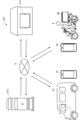
- FIG. 1 is a diagram showing an example of the system configuration of the dynamic display system 100.
- the dynamic display system 100 includes a plurality of (two in FIG. 1) deliveryman terminals 1A connected by a network 4 including a public wireless communication network typified by the Internet network and a mobile phone network. , 1B, a management server 2, and an administrator terminal 3.
- the management server 2 and the administrator terminal 3 collectively constitute a dynamic display device 5 according to the embodiment of the present invention. It should be noted that the management server 2 or the administrator terminal 3 may independently configure the dynamic display device 5.
- the network 4 also includes a closed communication network provided for each predetermined management area, such as a wireless LAN and Wi-Fi (Wireless Fidelity) (registered trademark).
- the deliveryman terminals 1A, 1B are stored in pockets of clothes, carrying bags, pouches, etc. of the deliverymen A, B who perform posting and delivery work, or the cradle of vehicles 6A, 6B used for posting and delivery work. It can be installed and used in such places.
- smartphones, tablet terminals, mobile phones, PDAs (Personal Digital Assistants), and various wearable terminals that can be connected to public wireless communication are collectively referred to as deliveryman terminals 1A and 1B.
- the deliveryman terminals 1A and 1B have a common configuration.
- the number of delivery terminal 1A, 1B may be three or more.
- the vehicles 6A and 6B are carry cars such as four-wheeled vehicles, motorcycles, bicycles, and wheelbarrows. As shown in FIG. 1, for example, they are widely used for posting and collecting postal items such as luggage, leaflets, letters, and postcards. Shown are a light vehicle 6A and a motorized bicycle 6B.
- the delivery staff members A and B may perform posting and delivery work on foot without using the vehicles 6A and 6B.
- ⁇ Delivery terminal 1A, 1B> First, the deliveryman terminals 1A and 1B will be described. Various application software can be installed in the deliveryman terminals 1A and 1B, and the deliveryman terminals 1A and 1B according to the present embodiment configure a dynamic display system by the application software installed in the smartphone. By using a commercially available smartphone, it is possible to reduce the cost of building the system.
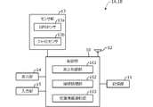
- FIG. 2 is a block diagram showing a schematic configuration of the deliveryman terminals 1A and 1B.
- the deliveryman terminal 1A has a control unit 10, a storage unit 11, a wireless unit 12, a sensor unit 13, a display unit 14, and an input unit 15.
- the storage unit 11 is composed of a semiconductor memory, a hard disk, or the like.
- the storage unit 11 stores various information such as an operating system (OS), software including application programs for supporting posting and delivery work, map information such as road maps and residential maps, customer information of delivery destinations, and the like.
- OS operating system
- map information such as road maps and residential maps
- customer information of delivery destinations and the like.
- the customer information includes a delivery address, a telephone number, and information associated with the customer such as the presence or absence of a delivery box.
- the software, map information, and customer information may be stored in the storage unit 11 in advance, or may be acquired from the management server 2.
- the wireless unit 12 has a DSP (Digital Signal Processor) and the like, and is configured to be capable of wireless communication with the management server 2 via a wireless communication network represented by a mobile phone network such as 3G, LTE, 4G, and 5G.
- the wireless unit 12 may be configured to include a proximity wireless communication unit (not shown) to which a proximity wireless communication technology such as Wi-Fi (registered trademark) or Bluetooth (registered trademark) can be applied.
- the wireless unit 12 transmits a login ID (also referred to as “delivery person ID”) for identifying the delivery persons A and B, current position information of the delivery persons A and B or the vehicles 6A and 6B, speed information and the like to the management server 2. be able to.
- the sensor unit 13 receives positioning signals from a plurality of GPS satellites and measures the absolute positions (latitude and longitude) of the corresponding delivery personnel A and B from a GPS sensor 13a and a gyro sensor 13b that detects angular velocity. Composed.
- AGPS Assisted Global Positioning System
- the display unit 14 is composed of a display device such as a liquid crystal display or an organic EL panel. In response to an instruction from the control unit 10, the display unit 14 displays a map, an operation button icon for a touch panel, and the like, and also displays the current position of the delivery personnel A, B or the vehicles 6A, 6B, the vicinity of the current position, the delivery destination. It is possible to display various information such as a map in the vicinity.
- the input unit 15 is composed of physical switches such as a numeric keypad operated by the deliverers A and B, and an input device (not shown) such as a touch panel provided so as to be superimposed on the display surface of the display unit 14.
- a signal based on the operation input from the input unit 15, for example, the ten keys pressed by the delivery staff members A and B and the touch panel touchdown is output to the control unit 10, whereby the delivery member performs operations such as switching the screen display of the display unit 14.
- a and B can do.
- the deliveryman terminals 1A and 1B can be provided with a speaker, a vibrator, a light, a microphone, etc. in addition to the above.
- the speaker, the vibrator, and the light notify the delivery staff of various information by sound, vibration, and light.
- the speaker outputs a voice to the deliveryman
- the microphone collects the voice or the like emitted by the deliveryman.
- various information can be output by voice from the speaker, and various commands by the deliveryman, which are voice-input via the microphone, can be input to the control unit 10 by using voice recognition technology.
- the control unit 10 is configured to include a microprocessor having a CPU, RAM, ROM, I / O and the like.
- the CPU executes a program stored in advance and exchanges signals with the storage unit 11, the wireless unit 12, the sensor unit 13, the display unit 14, and the input unit 15.
- the control unit 10 has a display control unit 101, a connection processing unit 102, and a position information notification unit 103 as a functional configuration.
- the display control unit 101 generates an image signal and transmits the image signal to the display unit 14 according to the operation of the input unit 15 or the reception of various information by the wireless unit 12, so that the screen display by the display unit 14 is performed.
- the screen display displayed on the display unit 14 by the display control unit 101 includes a login screen for logging in to the dynamic display system 100.
- the connection processing unit 102 transmits the login ID and password input by the delivery agents A and B via the input unit 15 to the management server 2 via the wireless unit 12 on the login screen displayed on the display unit 14.
- the deliveryman terminals 1A and 1B are connected to the management server 2 in a communicable state.
- This log-in input by the delivery member is executed when the delivery member starts work, that is, when the delivery member departs from the delivery site.
- the connection processing unit 102 transmits the logout to the management server 2 via the wireless unit 12.
- the communication connection between the deliveryman terminals 1A and 1B and the management server 2 is terminated.
- the logout input by the deliveryman is executed at the end of the deliveryman's day, that is, when the deliveryman returns to the delivery site. Note that the logout may be automatically executed based on the time and position information when the delivery member returns to the delivery base.
- the position information notifying unit 103 calculates the current position information of the delivery agents A and B or the vehicles 6A and 6B that move with the delivery agent terminals 1A and 1B calculated based on the GPS signal received by the sensor unit 13 (GPS sensor 13a). Is transmitted to the management server 2 at predetermined time intervals (for example, one second intervals) in association with the delivery person ID via the wireless unit 12.
- the positions of the deliverers A and B or the vehicles 6A and 6B change from moment to moment. Therefore, when the current position information is acquired at a predetermined time interval, the position obtained from the latest current position information and the actual position are strict. In some cases, they don't match. However, since the deviation is small, the position obtained from the current position information acquired at a predetermined time interval can be regarded as the current position.
- burst transmission a predetermined time interval
- the acquisition time interval for example, one second interval
- the number of transmissions at a time when a plurality of burst transmissions are collectively performed.
- management server 2 ⁇ Management server 2> Next, the management server 2 will be described. Although the management server 2 is described as a single server having various functions in the present embodiment, it may be a distributed server configured by different servers for each function, or a cloud server (virtual server). May be realized.
- a cloud server virtual server
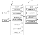
- FIG. 3 is a block diagram showing a schematic configuration of the management server 2.
- the management server 2 has a control unit 20, a storage unit 21, a communication unit 22, a display unit 24, and an input unit 25.
- the display unit 24 and the input unit 25 can be omitted. Further, the display unit 24 and the input unit 25 can be configured by another information terminal (not shown) connected to the management server 2.
- the storage unit 21 is composed of a semiconductor memory, a hard disk drive, or the like.
- the storage unit 21 stores an operating system (OS), software called an application, and various other information. Therefore, various storage areas such as a deliveryman information area 211, a vehicle information area 212, a posting destination or delivery destination information area 213, and a map information area 214 are secured in the storage unit 21.
- the information area is, for example, a table in the database management system.
- the deliveryman information area 211 for each employee ID (also referred to as “deliveryman ID”) that is the identification information of the deliverymen A and B, basic information about the deliverymen A and B, for example, the deliveryman A. , B, the delivery base of the affiliation, the delivery group information of the delivery group of the affiliation, etc. are stored. Further, the delivery person information area 211 stores information on the areas in charge of which the delivery groups to which the delivery persons A and B belong are in charge of posting and delivery work.
- employee ID also referred to as “deliveryman ID”
- basic information about the deliverymen A and B for example, the deliveryman A. , B, the delivery base of the affiliation, the delivery group information of the delivery group of the affiliation, etc. are stored.
- the delivery person information area 211 stores information on the areas in charge of which the delivery groups to which the delivery persons A and B belong are in charge of posting and delivery work.
- the information on the charge area stored in the delivery staff information area 211 includes the position information (latitude, longitude) and scale information of the representative point (center point) when each charge area is displayed on the map, or each charge area. Includes position information (latitude, longitude) of diagonal vertices when is displayed on the map.
- a vehicle ID used as a vehicle used by the deliveryman that is, a vehicle ID that is identification information of the vehicles 6A and 6B is stored in association with the deliveryman ID.
- the association of the vehicle ID with the delivery person ID is set in advance by the delivery site manager prior to the start of posting or delivery work for one day, for example.
- the vehicle information area 212 stores, for each vehicle ID, information about the vehicle, such as the type of vehicle such as a four-wheeled vehicle, a motorcycle, a bicycle, and the size of the luggage compartment.
- the posting destination or delivery destination information area 213 stores delivery destination information including the delivery destination address and telephone number, the delivery area including the delivery destination, and the like. It should be noted that the delivery area is an area preset by the administrator of the delivery base for the sake of convenience in assigning posting and delivery work to each delivery member, and for example, delivery destinations of 10 to 30 households corresponding to one or more blocks. Composed of.
- the area in charge assigned to each delivery group to which the delivery agents A and B stored in the delivery agent information area 211 are composed of a plurality of delivery areas.
- the delivery members A and B belonging to each delivery group are in charge of posting and delivery work in the area in charge assigned to the delivery group to which they belong.
- map information such as a road map and a residential map is stored in advance.
- the map information includes road link information, display map data for displaying the background of roads and road maps, and the like. These map information are updated regularly.
- the communication unit 22 implements a communication protocol capable of performing wireless communication such as 3G, LTE, 4G, and 5G when transmitting / receiving with the deliveryman terminals 1A and 1B.
- the communication unit 22 implements a communication protocol capable of performing wired communication (for example, an internet line or the like) or wireless communication when transmitting / receiving to / from the administrator terminal 3.
- the control unit 20 is configured to include a processor having a CPU, RAM, ROM, I / O and the like.
- the control unit 20 has, as a functional configuration, a connection processing unit 201, a position information acquisition unit 202, a display control unit 203, a display mode switching unit 204, a stay determination unit 205, a communication failure determination unit 206, and information. And an output unit 207.
- the connection processing unit 201 executes login processing from the deliveryman terminals 1A and 1B and performs connection processing with the deliveryman terminals 1A and 1B. Further, the connection processing unit 201 executes logout processing from the deliveryman terminals 1A and 1B, and ends the connection with the deliveryman terminals 1A and 1B. Further, the connection processing unit 201 performs login processing from the administrator terminal 3 to perform connection processing with the administrator terminal 3, and performs logout processing from the administrator terminal 3 to communicate with the administrator terminal 3. Terminate the connection.
- the position information acquisition unit 202 acquires various information by receiving the data transmitted from the deliveryman terminals 1A and 1B to the management server 2 via the communication unit 22.
- the information acquired by the position information acquisition unit 202 includes the position information of the deliverers A and B or the vehicles 6A and 6B transmitted from the position information notification unit 103 of each of the deliveryman terminals 1A and 1B.
- the position information is specifically represented by latitude and longitude.
- the display control unit 203 generates an image signal and transmits it to the administrator terminal 3 in response to a command from the administrator terminal 3, and causes the display unit 34 of the administrator terminal 3 to display various images.
- the stay determination unit 205 determines that the delivery personnel A, B or the vehicles 6A, 6B are within a predetermined range (for example, within a radius of 5 m) for a predetermined time or more (for example, It is determined whether or not the user is staying for 3 minutes or more).
- the incommunicability determination unit 206 determines whether the delivery agents A and B or the vehicles 6A and 6B are in an incommunicable state in which the position information acquisition unit 202 cannot acquire position information for a predetermined time or longer (for example, 3 minutes or longer). To judge.
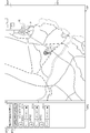
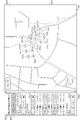
- FIG. 4, FIG. 5, and FIG. 7A to FIG. 8 are examples of the screen display DP displayed on the display unit 34 of the administrator terminal 3, and are the administrator terminals of the delivery bases that manage the 30 delivery agents 01 to 30. 3 shows a screen display DP displayed in 3.
- FIG. 4 shows an initial screen display DP displayed on the display unit 34 of the administrator terminal 3 when the connection processing unit 201 performs connection processing with the administrator terminal 3 in response to a command from the administrator terminal 3.
- the dynamic image DP1 in which the position icons PI01 to PI30 indicating the current positions P01 to P30 of the delivery staff 01 to 30 are superimposed and displayed on the map image MAP is displayed, and the menu is displayed on the left side of the dynamic image DP1.
- DP2 is displayed.
- the position is displayed in real time (dynamic display) (all group display mode).
- the scale and center position of the map in the dynamic image DP1 can be appropriately changed via the input unit 35 of the administrator terminal 3, for example, a touch panel provided on the display unit 34, a mouse, or the like.
- the position icon PI indicating the current position P of the deliveryman is displayed by another deliveryman. Is displayed in a mode different from the position icon PI indicating the current position P. For example, the display color of the position icon PI is changed, or the position icon PI is displayed in a blinking manner. A message or the like may be displayed on the screen display DP to warn that there is a delivery person who is determined to be in a staying state.
- an automatic switching button BT1 for turning on or off the automatic switching function for automatically switching the display mode of the dynamic image DP1 is displayed as described later.
- map display buttons BT61 to BT63 for displaying only the movements of the delivery members of the delivery groups 1 to 3 in the movement image DP1 for each of the delivery groups 1 to 3 managed by the delivery base manager, Drop-down menus DD1 to DD3 are displayed.
- an all-display button BT2 that displays all the movements of the delivery staff 01 to 30, and an all-non-display button BT3 that does not display all of them. Further, an all-fold button BT4 for displaying all the drop-down menus DD1 to DD3 in a folded state, and an all-fold button BT5 for displaying all the folded-down menus are displayed.
- 5 and 7A to 8 are examples of the screen display DP displayed when the map display buttons BT61 to BT63 are pressed via the touch panel (input unit 35) of the administrator terminal 3, respectively.
- the five current delivery positions P06 of the five delivery members 06 to 10 logged in to the dynamic display system 100 are logged in.
- Position icons PI06 to PI10 indicating P10 to P10 are displayed in real time (first group display mode).
- the current positions of the delivery members 01 to 05 who are logged out from the activity display system 100 are not displayed.
- the name of the displayed delivery group "Group 1" is displayed.
- FIG. 6 is a diagram for explaining the states of the deliveryman terminals 1A and 1B.
- the state (status, state of the delivery person) of each delivery agent terminal 1A, 1B includes a login state and a logout state.
- the position information acquisition unit 202 of the management server 2 has acquired a position information within a predetermined time (for example, 3 minutes), and has a communicable state within a predetermined time.
- There is an incommunicable state where the location information is not acquired.
- the incommunicable state includes battery exhaustion of the deliveryman terminals 1A and 1B, trouble of the network 4, and the like.
- the position icon PI10 indicating the current position P10 obtained last is a position icon PI indicating the current position P of another delivery person. Is displayed in a different manner. For example, the display color of the position icon PI10 is changed, or the position icon PI blinks and is displayed in a recognizable manner. That is, as a result of the determination made by the communication inability determination unit 206, it is displayed in a recognizable manner that the deliveryman 10 is in an incommunicable state in which the position information cannot be acquired.
- the dropdown menu DD1 of the delivery group 1 displayed in the dynamic image DP1 is highlighted.
- the drop-down menu DD1 five out of ten delivery members belonging to the delivery group 1 are logged in or the remaining five are logged out.
- the drop-down menu DD1 when the drop-down menu DD1 is expanded, the status (logged-in state or logged-out state) of each of the ten delivery members 01 to 10 belonging to the delivery group 1 is displayed in an identifiable manner. ..
- the type of vehicle in use is displayed in addition to the status, and a check box CB is displayed.
- the display can be switched individually.
- position icons PI11 to PI20 indicating the current positions P11 to P20 of the ten delivery members 11 to 20 belonging to the delivery group 2 are displayed in real time (second group display mode). ). Comparing the map images MAP of FIGS. 7A and 7B, the map image MAP of FIG. 7B is displayed in a wider area or reduced than the map image MAP of FIG. 7A.
- the delivery base administrator is abnormal. Can be noticed. That is, when the delivery person is moving to an unusual place as shown in FIG. 7B, the scale and display position of the map will be different from the normal state, and the administrator will be in a situation different from the normal situation. Can be easily recognized.
- the scale and center of the map in the dynamic image DP1 are displayed so that the current positions of all the delivery members who are logged in among the delivery members belonging to each delivery group can be displayed.
- the position is adjusted automatically.
- an area preset for each delivery group 1-3 for example, an area in charge is displayed regardless of the current position of the delivery member. You may set it.
- the position icons PI21 to P23 indicating the current positions P21 to P23 of the three delivery members 21 to 23 who are logged in.
- the PI 23 is displayed in real time (third group display mode).
- the automatic switching button BT1 is highlighted.
- the automatic switching button BT1 of the menu DP2 is pressed via the touch panel (input unit 35) of the administrator terminal 3 in the screen display DP of FIGS. 4 to 7B, the automatic switching button BT1 is highlighted and the dynamic image DP1 is displayed.
- the automatic switching function that automatically switches the display mode is turned on.
- the automatic switching function is on and the scale or center position of the map in the dynamic image DP1 is operated via the touch panel (input unit 35) of the administrator terminal 3, the automatic switching function is turned off. In this case, the automatic switching function is turned off in the display mode at the time when the automatic switching function was turned off.
- the display control unit 203 has a display mode switching unit 204.
- the display mode switching unit 204 displays the dynamics of the delivery members for each of the delivery groups 1 to 3.
- the first to third group display modes are sequentially switched.
- the first to third group display modes are sequentially switched at predetermined time intervals (for example, 5 seconds).
- the all group display mode for displaying the dynamics of the delivery members of all the delivery groups 1 to 3 and the first to third group display modes may be automatically switched at predetermined intervals.
- the information output unit 207 in FIG. 3 outputs various information by transmitting data from the management server 2 to the administrator terminal 3 via the communication unit 22.
- the information output by the information output unit 207 includes an image signal and the like generated by the display control unit 203 and transmitted to the administrator terminal 3.
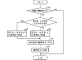
- FIG. 9 is a flowchart showing an example of processing executed by the CPU of the management server 2 according to a program stored in advance. The process shown in this flowchart is started when a command from the administrator terminal 3 is received, and is repeated in a predetermined cycle.
- step S1 it is determined by the processing in the display mode switching unit 204 whether or not the automatic switching function is on. If the result in step S1 is affirmative, the process proceeds to step S2. In step S2, it is determined whether or not a predetermined time has elapsed after switching to the currently displayed display mode. If the result is affirmative, the process proceeds to step S3, and if not, the process proceeds to step S4.
- step S3 the position information acquisition unit 202 performs processing to read the position information of the delivery agents A and B displayed in the display mode to be displayed next.
- step S4 the position information of the delivery persons A and B displayed in the currently displayed display mode is read.
- step S5 the image signal of the dynamic image DP1 is generated based on the position information acquired in step S3 or S4 by the processing in the display control unit 203.
- step S6 the image signal generated in step S5 is transmitted to the administrator terminal 3 by the processing of the information output unit 207.
- the administrator of the delivery site can perform a simple operation by simply pressing the automatic switching button BT1 displayed on the display unit 34 via the input unit 35 such as a touch panel or a mouse provided on the display unit 34 of the administrator terminal 3. Therefore, it is possible to confirm the dynamics of the managed delivery person in a good manner. Since the dynamics of delivery agents are displayed for each delivery group that performs delivery work within the area in charge, if there are many delivery agents to be managed or if the delivery agents are distributed in multiple areas that are separated from each other. Even, it is possible to grasp the individual movements of the delivery staff.
- the administrator terminal 3 is used by the delivery site administrator to confirm the current positions of the delivery members A and B who perform posting and delivery work in real time.
- the administrator terminal 3 includes various computers such as a personal computer, a tablet terminal, and a smart phone installed at the delivery base, and exchanges information with the management server 2 via the network 4.
- FIG. 10 is a block diagram showing a schematic configuration of the administrator terminal 3. As illustrated in FIG. 10, the administrator terminal 3 includes a control unit 30, a storage unit 31, a communication unit 32, a display unit 34, and an input unit 35.
- the storage unit 31 is composed of a semiconductor memory, a hard disk drive, or the like.
- the storage unit 31 stores an operating system (OS), software called an application, and various other information.
- OS operating system
- the software stored in the storage unit 31 includes application programs for managing posting and delivery work.
- the communication unit 32 is equipped with a communication protocol capable of wired communication (for example, Internet line) or wireless communication such as 3G, LTE, 4G, and 5G, and connects and receives with the management server 2.
- a communication protocol capable of wired communication (for example, Internet line) or wireless communication such as 3G, LTE, 4G, and 5G, and connects and receives with the management server 2.
- the display unit 34 is configured by a display device such as a liquid crystal display or an organic EL panel, and displays a map, an icon of an operation button for a touch panel, or the like in response to an instruction from the control unit 30. Further, the display unit 34 displays various images based on the image signal transmitted from the information output unit 207 of the management server 2.
- the input unit 35 is configured by a physical switch such as a numeric keypad operated by an administrator, an input device (not shown) such as a touch panel provided on the display surface of the display unit 34, and the like. A command for switching the display screen of the display unit 34 is input via the input unit 35.
- the area in charge of each delivery group (sorting of delivery destinations) can be set via the input unit 35.
- the control unit 30 includes a processor having a CPU, a RAM, a ROM, an I / O and the like.
- the control unit 30 includes a display control unit 301, a connection processing unit 302, a dynamic display requesting unit 303, and a server information acquisition unit 304 as a functional configuration.
- the display control unit 301 controls the screen display by the display unit 34 by generating an image signal according to the operation of the input unit 35 and transmitting it to the display unit 34.
- the screen displayed by the display control unit 301 on the display unit 34 includes a login screen for logging in to the dynamic display system 100, a setting screen for setting the area in charge of each delivery group, and the like.
- the connection processing unit 302 executes a login process for the management server 2 by using, for example, an identification number (base manager ID) identifying a manager or a person in charge of the delivery base and a password.
- an identification number base manager ID
- the dynamic display requesting unit 303 transmits an output request (command) of an image signal for displaying the dynamic image DP1 to the management server 2 in response to the operation of the input unit 35 by the administrator. For example, when the login process is executed by the connection processing unit 302, at the same time, an output request of an image signal for displaying the dynamic image DP1 is transmitted to the management server 2.
- the server information acquisition unit 304 acquires the image signal and the like transmitted from the management server 2 (information output unit 207).
- various images (FIGS. 4, 5, and 7A to 8) are displayed on the display unit 34.
- the delivery staffs A and B driving the vehicles 6A and 6B respectively enter the input unit 15 on the login screen displayed on the display unit 14 of the deliveryman terminals 1A and 1B when departing from the delivery base, that is, at the start of work. Enter your login ID and password via.
- the management server 2 performs a connection process with the deliveryman terminals 1A and 1B.
- the deliveryman terminals 1A and 1B communicate with the management server 2 at predetermined time intervals (for example, 1 second intervals), and transmit the position information of the delivery agents A and B or the vehicles 6A and 6B to the management server 2.
- the communication between the deliveryman terminals 1A, 1B and the management server 2 is continued until the deliveryman terminals 1A, 1B log out.
- the administrator of the delivery site operates the touch panel (input unit 35) of the administrator terminal 3 to activate the application program for managing the posting and delivery work, and displays the login screen on the display unit 34. Enter the site administrator ID and password.
- the management server 2 performs a connection process with the administrator terminal 3.
- the management server 2 In response to a command from the administrator terminal 3, the management server 2 generates an image signal of the dynamic image DP1 and the menu DP2 that displays the current position P of the delivery person corresponding to the site administrator ID, and sends the image signal to the administrator terminal 3. Send.
- the delivery site manager presses the automatic switching function BT1 of the menu DP2 displayed on the display unit 34 to turn on the automatic switching function, the dynamic images DP1 for each delivery group are automatically and sequentially switched and displayed. (Steps S1 to S6 in FIG. 9) (FIGS. 4, 5, and 7A to 8).
- the delivery site manager can check the dynamics of the delivery staff under management in a good manner.
- the map becomes a wide area display, and a position icon PI indicating the current location of each delivery agent is displayed. It is difficult to grasp the current position and movement of each delivery person due to overlapping each other.
- the user who is the administrator himself / herself operates the scale and center position of the map as shown in FIGS. 5 and 7A to 8. Becomes complicated for.
- the dynamic image DP1 is displayed by automatically switching the display modes of FIG. 5, FIG. 7A to FIG. 8 or FIG. 4, FIG. 5, and FIG. 7A to FIG. , It is possible to grasp the dynamics of the delivery staff, which change from moment to moment, from various aspects.
- the screen displays DP in a plurality of display modes can be displayed in a multi-display manner, but in this case, the individual screen displays DP become smaller, or A large display is required as the display unit 34.
- the display mode is automatically switched at appropriate time intervals to display the dynamic image DP1. Therefore, for example, even if the display unit 34 is a relatively small display such as a tablet terminal, It is possible to grasp the dynamics of the delivery staff who change from moment to moment from various aspects.
- the dynamic display device 5 displays the current positions P of a plurality of delivery persons belonging to any of the plurality of delivery groups 1 to 3 in real time (FIGS. 4, 5, and 7A to 8).
- the dynamic display device 5 displays the position information on the map image MAP based on the position information acquisition unit 202 that acquires the position information of each of the plurality of delivery staff, the display unit 34, and the position information acquired by the position information acquisition unit 202.
- the display control unit 203 that controls the display unit 34 to display the position icon PI indicating the current position P of the deliveryman in real time (FIGS. 3 and 10).
- the display control unit 203 switches a plurality of display modes including first to third group display modes in which the position icons PI of delivery persons belonging to the delivery groups 1 to 3 are displayed in real time at predetermined time intervals. (FIG. 3).
- first to third group display modes in which the position icons PI of delivery persons belonging to the delivery groups 1 to 3 are displayed in real time at predetermined time intervals.
- FIG. 3 the current locations of multiple delivery agents are displayed for each group, so that the delivery site manager can grasp the current locations of all the delivery agents in a good manner, and also the current status of each delivery agent in detail. Can be grasped.
- the activity display device 5 further includes an input unit 35 that receives a command from the delivery site manager (FIG. 10).
- the display control unit 203 stops the switching of the display mode by the display mode switching unit 204 according to the command received by the input unit 35. With this, the automatic switching can be stopped as needed, so that the movement of the delivery person can be grasped in a good manner even when there is a delivery group or delivery person who wants attention or when there is an area that needs attention.
- the input unit 35 receives a command from the administrator when the automatic switch button BT1 displayed on the display unit 34 so as to be pressed is pressed by the administrator.
- the administrator can stop the automatic switching of the display mode by a simple operation, if necessary.
- the input unit 35 confirms that any one of the plurality of map display buttons BT61 to BT63 corresponding to each of the plurality of delivery groups 1 to 3 displayed on the display unit 34 is selectable by the administrator. Accept the command from the administrator as a trigger.
- the display mode switching unit 204 switches the display mode so as to display the delivery group selected by the administrator.
- the display control unit 203 stops the switching of the display mode by the display mode switching unit 204 according to the command received by the input unit 35.
- the administrator can quickly and quickly switch to the display mode for each delivery group that he or she wants to pay attention to with a simple operation. Also, when the display mode is switched by the operation of the administrator, the automatic switching of the display mode is stopped, so the display of the delivery group, which the administrator is paying attention to, is not automatically switched. It is possible to provide an on-screen display.
- the map image MAP is displayed on the display unit 34 so as to be operable to change the scale and position.
- the input unit 35 receives a command from the administrator when the administrator operates the map image MAP.
- the display control unit 203 stops the switching of the display mode by the display mode switching unit 204 according to the command received by the input unit 35.
- the display control unit 203 belongs to the delivery groups 1 to 3 whose position information has been acquired by the position information acquisition unit 202.
- the display unit 34 is controlled to display the position icons PI of all the delivery staff in real time.
- the display mode switching unit 204 switches at a predetermined time interval a plurality of display modes further including the all group display mode in which the plurality of delivery groups 1 to 3 are simultaneously displayed.
- the display control unit 203 is located within the assigned area preset for each delivery group 1 to 3.
- the display unit 34 is controlled so that the position icon PI of the deliveryman is displayed in real time.
- the dynamic display device 5 determines whether or not the delivery staff is in a staying state in which the delivery staff stays within a predetermined range for a predetermined time or more based on the position information acquired by the position information acquiring unit 202.
- the unit 205 is further provided (FIG. 3).
- the display control unit 203 displays the position icon PI of the delivery person who is determined to be in the staying state by the staying determination unit 205 in a manner distinguishable from the position icons PI of other delivery members.
- the display unit 34 is controlled so as to display a staying warning image that warns a delivery person who is judged to be staying by the staying judging unit 205.
- the dynamic display device 5 further includes a communication failure determination unit 206 that determines whether or not the deliveryman is in a communication disabled state in which the position information acquisition unit 202 cannot acquire the position information for a predetermined time or longer (( (Fig. 3).
- the display control unit 203 displays the position icon PI of the delivery person who is determined to be in the incommunicable state by the communication inability determination unit 206 in a manner distinguishable from the position icons PI of other delivery members. To control. As a result, it is possible to detect a failure or the like of the deliveryman terminals 1A and 1B at an early stage.
- the movement display device 5 displays the movement of a deliveryman who performs posting and delivery work in real time.
- the movement display device can display a plurality of display targets belonging to any of a plurality of groups. Anything that displays the current position in real time may be used.
- the movements of visitors of a large facility may be displayed in real time for each group of visitors or for each area where they are staying.
- the position information acquisition unit 202 acquires the position information calculated on the deliveryman terminal 1A, 1B side, but the configuration of the position information acquisition unit that acquires the position information of the display target is not limited to this. Absent.
- the position may be calculated by the management server 2 based on the GPS signal or the like received by the deliveryman terminals 1A and 1B.
- the command from the user who is the administrator is accepted by the touch panel, the mouse, or the like provided on the display unit 34 of the administrator terminal 3, but the command accepting unit that accepts the command from the user is like this.
- the administrator terminal 3 may be provided with a microphone to receive an instruction by the user's voice, and the administrator terminal 3 may be provided with a camera to receive an instruction by the user's gesture.
- the display control unit 203 of the management server 2 controls the display unit 34 of the administrator terminal 3, but the display control unit that controls the display unit is not limited to this. That is, the display control unit 301 of the administrator terminal 3 may generate the image signal of the screen display DP as shown in FIGS. 4, 5, and 7A to 8.
- the present invention has been described as the dynamic display device 5, but the present invention can also be used as a dynamic display method for displaying the current positions of a plurality of display targets belonging to any of a plurality of groups in real time. That is, the dynamic display method acquires position information of each of a plurality of delivery persons (steps S3 and S4 in FIG. 9), and indicates the current position P of the delivery person on the map image MAP based on the acquired position information.
- the display unit 34 is controlled to display the position icon PI in real time (steps S5 and S6), and the first to third group display modes for displaying the position icons PI of the delivery staff members belonging to the delivery groups 1 to 3 in real time are displayed. Switching among a plurality of display modes including the display mode at predetermined time intervals (steps S1 and S2) is included.
- the activity display program is stored in the storage unit 21 of the management server 2, but it may be stored in an external storage medium such as a flash memory. It is also possible to obtain the dynamic display program from outside the dynamic display system 100 via the network 4.
Landscapes
- Engineering & Computer Science (AREA)
- Theoretical Computer Science (AREA)
- Physics & Mathematics (AREA)
- Business, Economics & Management (AREA)
- General Physics & Mathematics (AREA)
- Mathematical Physics (AREA)
- Educational Administration (AREA)
- Educational Technology (AREA)
- Economics (AREA)
- Entrepreneurship & Innovation (AREA)
- Development Economics (AREA)
- Human Resources & Organizations (AREA)
- Marketing (AREA)
- Operations Research (AREA)
- Quality & Reliability (AREA)
- Strategic Management (AREA)
- Tourism & Hospitality (AREA)
- General Business, Economics & Management (AREA)
- User Interface Of Digital Computer (AREA)
- Management, Administration, Business Operations System, And Electronic Commerce (AREA)
- Instructional Devices (AREA)
- Navigation (AREA)
Abstract
第1グループと第2グループとを含む複数のグループのいずれかに属する複数の表示対象の現在位置をリアルタイムで表示する動態表示装置(5)は、複数の表示対象のそれぞれの位置情報を取得する位置情報取得部(202)と、表示部と、位置情報取得部(202)により取得された位置情報に基づいて、地図画像上に表示対象の現在位置を示すアイコン画像をリアルタイムで表示するように表示部を制御する表示制御部(203)とを備える。表示制御部(203)は、第1グループに属する表示対象のアイコン画像をリアルタイムで表示する第1グループ表示モードと、第2グループに属する表示対象のアイコン画像をリアルタイムで表示する第2グループ表示モードとを含む複数の表示モードを所定の時間間隔で切り替える表示モード切替部(204)を有する。
Description
本発明は、複数の表示対象の動態を表示する動態表示装置、動態表示システム、動態表示方法および動態表示プログラムに関する。
この種の技術として、従来、荷物を輸送する複数の車両の現在位置を、車両の運行を管理するユーザの端末に表示するようにした装置が知られている(例えば特許文献1参照)。この特許文献1記載の装置では、ユーザにより端末を介して指定された出発地や目的地、車両種別等の条件を満足する車両を抽出し、ユーザの端末の画面に表示された地図データに重畳して、抽出された車両の現在位置を表す車両マークをリアルタイムで表示する。
しかしながら、上記特許文献1記載の装置では、条件を満たす車両の動態が単一の地図上に表示されるだけであり、表示される車両数が多い場合や表示される車両が互いに離間した複数のエリアに分散しているような場合には、各車両の動態をユーザにとって良好な態様で表示することが難しい。
すなわち、上記特許文献1記載の装置では、単一の地図上に全ての車両が表示されるため、車両が広範囲に分散している場合は地図画面が広域表示となり、個々の車両の動きを把握することが難しい。また、車両が互いに離間した複数のエリアに分散している場合、個々の車両の動きを見るには地図画面を操作して表示位置を調整する必要があり、ユーザにとって手間となる。また、表示位置の異なる複数の地図画面を同時に表示するには、複数のディスプレイあるいは大型のディスプレイが必要となり、装置全体のコストが増大する。
本発明の一態様は、第1グループと第2グループとを含む複数のグループのいずれかに属する複数の表示対象の現在位置をリアルタイムで表示する動態表示装置であって、複数の表示対象のそれぞれの位置情報を取得する位置情報取得部と、表示部と、位置情報取得部により取得された位置情報に基づいて、地図画像上に表示対象の現在位置を示すアイコン画像をリアルタイムで表示するように表示部を制御する表示制御部と、を備える。表示制御部は、第1グループに属する表示対象のアイコン画像をリアルタイムで表示する第1グループ表示モードと、第2グループに属する表示対象のアイコン画像をリアルタイムで表示する第2グループ表示モードと、を含む複数の表示モードを所定の時間間隔で切り替える表示モード切替部を有する。
本発明の別の態様である動態表示システムは、動態表示装置と、表示対象とともに移動し、表示対象の位置情報を動態表示装置に送信する移動端末と、を備える。
本発明のさらなる別の態様は、第1グループと第2グループとを含む複数のグループのいずれかに属する複数の表示対象の現在位置をリアルタイムで表示する動態表示方法であって、複数の表示対象のそれぞれの位置情報を取得し、取得した位置情報に基づいて、地図画像上に表示対象の現在位置を示すアイコン画像をリアルタイムで表示するように表示部を制御し、第1グループに属する表示対象のアイコン画像をリアルタイムで表示する第1グループ表示モードと、第2グループに属する表示対象のアイコン画像をリアルタイムで表示する第2グループ表示モードと、を含む複数の表示モードを所定の時間間隔で切り替えることを含む。
本発明のさらなる別の態様は、第1グループと第2グループとを含む複数のグループのいずれかに属する複数の表示対象の現在位置をリアルタイムで表示する動態表示プログラムであって、複数の表示対象のそれぞれの位置情報を取得する手順と、取得した位置情報に基づいて、地図画像上に表示対象の現在位置を示すアイコン画像をリアルタイムで表示するように表示部を制御する手順と、第1グループに属する表示対象のアイコン画像をリアルタイムで表示する第1グループ表示モードと、第2グループに属する表示対象のアイコン画像をリアルタイムで表示する第2グループ表示モードと、を含む複数の表示モードを所定の時間間隔で切り替える手順と、をコンピュータに実行させる。
本発明によれば、表示対象の動態を良好な態様で表示することができる。
以下、図1~図10を参照して本発明の一実施形態について説明する。本発明の実施形態に係る動態表示装置は、外勤中の担当者や大型施設の来場者等の動きをリアルタイムで表示する種々の業種の動態表示システムに用いることができる。
以下では、営業担当者が外回りを行う、あるいは配達員が荷物、チラシ、手紙、はがき等の郵便物等のポスティングや配達を行うポスティングや配達等の各種サービス、特に、配達員が荷物、チラシ、手紙、はがき等の郵便物等のポスティングや配達を行うポスティングや配達サービスの動態表示システムに適用する例を説明する。すなわち、配送業者や郵便局などの配送拠点でポスティングや配達の作業を行う配達員の動きをリアルタイムで表示する例を説明する。
このようなポスティングや配達サービスでは、配達時の配達員の動き(動態)を管理者が把握しやすい良好な態様で表示することが好ましい。そこで本実施形態では、表示すべき配達員が多い場合や、表示すべき配達員が互いに離間した複数のエリアに分散しているような場合にも、各配達員の動態を管理者にとって良好な態様で表示するよう、以下のように動態表示装置を構成する。
[動態表示システム100の機能構成]
まず、本発明の実施形態に係る動態表示システム100の機能構成について説明する。図1は、動態表示システム100のシステム構成の一例を示す図である。図1に示すように、動態表示システム100は、インターネット網や携帯電話網等に代表される公衆無線通信網を含むネットワーク4で接続された、複数(図1では2台)の配達員端末1A,1Bと、管理サーバ2と、管理者端末3とを含んで構成される。
まず、本発明の実施形態に係る動態表示システム100の機能構成について説明する。図1は、動態表示システム100のシステム構成の一例を示す図である。図1に示すように、動態表示システム100は、インターネット網や携帯電話網等に代表される公衆無線通信網を含むネットワーク4で接続された、複数(図1では2台)の配達員端末1A,1Bと、管理サーバ2と、管理者端末3とを含んで構成される。
このような動態表示システム100のうち、管理サーバ2と管理者端末3とが全体として本発明の実施形態に係る動態表示装置5を構成する。なお、管理サーバ2または管理者端末3が単独で動態表示装置5を構成することもできる。なお、ネットワーク4には、所定の管理地域ごとに設けられた閉鎖的な通信網、例えば無線LAN、Wi-Fi(Wireless Fidelity)(登録商標)等も含まれる。
配達員端末1A,1Bは、ポスティングや配達の作業を行う配達員A,Bが衣服のポケット、携行する鞄、ポーチ等に収納し、あるいはポスティングや配達の作業に利用する車両6A,6Bのクレイドルなどに設置して使用することができる。本実施形態では、公衆無線通信接続可能なスマートフォンやタブレット端末、携帯電話、PDA(Personal Digital Assistant)、さらには各種ウェアラブル端末を、配達員端末1A,1Bと総称する。
配達員端末1Aと1Bとは共通の構成を有する。なお、配達員端末1A,1Bは3台以上でもよい。車両6A,6Bは、四輪車やオートバイ、自転車、手押し車等のキャリーカーであり、図1には、一例として、荷物、チラシ、手紙、はがき等の郵便物等のポスティングや集配に広く用いられている軽自動車6Aと原動機付自転車6Bとが示される。配達員A,Bは、車両6A,6Bを使用せずに徒歩でポスティングや配達の作業を行ってもよい。
次に、配達員端末1A,1B、管理サーバ2および管理者端末3の各構成について説明する。
<配達員端末1A,1B>
まず、配達員端末1A,1Bについて説明する。配達員端末1A,1Bには各種アプリケーションソフトウェアがインストール可能であり、本実施形態に係る配達員端末1A,1Bは、スマートフォンにインストールされたアプリケーションソフトウェアによって動態表示システムを構成する。市販のスマートフォンを利用することで、システムの構築にかかるコストを抑えることができる。
まず、配達員端末1A,1Bについて説明する。配達員端末1A,1Bには各種アプリケーションソフトウェアがインストール可能であり、本実施形態に係る配達員端末1A,1Bは、スマートフォンにインストールされたアプリケーションソフトウェアによって動態表示システムを構成する。市販のスマートフォンを利用することで、システムの構築にかかるコストを抑えることができる。
図2は、配達員端末1A,1Bの概略構成を示すブロック図である。図2に示すように、配達員端末1Aは、制御部10と、記憶部11と、無線部12と、センサ部13と、表示部14と、入力部15とを有する。
記憶部11は、半導体メモリやハードディスク等で構成される。記憶部11には、オペレーティングシステム(OS)や、ポスティングや配達の作業を支援するためのアプリケーションプログラムを含むソフトウェア、道路地図や住宅地図等の地図情報、配達先の顧客情報等、種々の情報が記憶される。顧客情報には、配達先の住所や電話番号の他、宅配ボックスの有無等の顧客に関連付けられた情報が含まれる。なお、ソフトウェア、地図情報、顧客情報については、それぞれを予め記憶部11に記憶しておいてもよく、あるいは管理サーバ2から取得してもよい。
無線部12は、DSP(Digital Signal Processor)等を有し、3G、LTE、4G、5G等の携帯電話網に代表される無線通信網を介し、管理サーバ2と無線通信可能に構成される。無線部12は、例えばWi-Fi(登録商標)、Bluetooth(登録商標)等の近接無線通信技術を適用可能な近接無線通信部(図示せず)を含むように構成されてもよい。無線部12は、配達員A,Bを識別するログインID(「配達員ID」ともいう)、配達員A,Bまたは車両6A,6Bの現在位置情報、速度情報等を管理サーバ2に送信することができる。
センサ部13は、複数のGPS衛星からの測位信号を受信して、対応する配達員A、Bの絶対位置(緯度、経度)を測定するGPSセンサ13aと、角速度を検出するジャイロセンサ13b等から構成される。GPS衛星からの測位信号の受信が不可能な場合、AGPS(Assisted Global Positioning System)通信を利用し、無線部12から取得される無線通信網の基地局情報によって配達員A,Bまたは車両6A,6Bの現在位置を算出することもできる。
表示部14は、液晶ディスプレイまたは有機ELパネル等の表示デバイスにより構成される。表示部14は、制御部10からの指示を受けて、地図やタッチパネル用の操作ボタンのアイコン等を表示するとともに、配達員A,Bまたは車両6A,6Bの現在位置、現在位置周辺、配達先付近の地図等の各種情報を表示することができる。
入力部15は、配達員A,Bによって操作されるテンキーなどの物理スイッチや表示部14の表示面に重ねて設けられたタッチパネル等の入力装置(図示せず)等で構成される。入力部15からの操作入力、例えば配達員A,Bによるテンキーの押下、タッチパネルの押下に基づいた信号は制御部10に出力され、これにより表示部14の画面表示の切替え等の操作を配達員A,Bが行うことができる。
なお、図示は省略するが、配達員端末1A,1Bは、この他にスピーカやバイブレータ、ライト、マイク等を備えることができる。スピーカやバイブレータ、ライトは、配達員に対し音や振動、光により各種情報を報知する。また、スピーカは、配達員に対し音声出力を行い、マイクは、配達員によって発せられた音声等を集音する。これにより、スピーカから各種情報を音声で出力するとともに、マイクを介して音声入力された配達員による各種指令を、音声認識技術を用いて制御部10に入力することができる。
制御部10は、CPU、RAM、ROM、I/O等を有するマイクロプロセッサを含んで構成される。CPUは、予め記憶されたプログラムを実行し、記憶部11、無線部12、センサ部13、表示部14および入力部15と信号の授受を行う。制御部10は、機能的構成として、表示制御部101と、接続処理部102と、位置情報通知部103とを有する。
表示制御部101は、入力部15の操作に応じて、あるいは無線部12による種々の情報の受信に応じて、画像信号を生成して表示部14に送信することで、表示部14による画面表示を制御する。表示制御部101が表示部14に表示させる画面表示には、動態表示システム100にログインするためのログイン画面等が含まれる。
接続処理部102は、表示部14に表示されるログイン画面において、入力部15を介して配達員A,Bにより入力されるログインIDおよびパスワードを、無線部12を介し管理サーバ2に送信する。これにより、配達員端末1A,1Bが管理サーバ2と通信可能な状態で接続される。この配達員によるログイン入力は、配達員の始業時、すなわち、配達員が配送拠点から出発するときに実行される。
また、接続処理部102は、入力部15を介してログアウトが入力されると、無線部12を介して管理サーバ2に対しログアウトを送信する。これにより、配達員端末1A,1Bと管理サーバ2との間の通信接続が終了される。この配達員によるログアウト入力は、配達員の終業時、すなわち、配達員が配送拠点に戻ったときに実行される。なお、ログアウトは、配達員が配送拠点に戻ったときに、時刻や位置情報に基づいて自動的に実行されてもよい。
位置情報通知部103は、センサ部13(GPSセンサ13a)により受信されたGPS信号に基づいて算出した配達員端末1A,1Bとともに移動する配達員A,Bまたは車両6A,6Bの現在位置情報等を、無線部12を介し、配達員IDに対応付けて所定の時間間隔(例えば1秒間隔)で管理サーバ2に送信する。
配達員A,Bまたは車両6A,6Bの位置は、時々刻々と変化するため、現在位置情報を所定時間間隔で取得する場合、直近の現在位置情報から求まる位置と実際の位置とは、厳密にいうと一致しないことがある。しかしながら、そのずれは小さいため、所定時間間隔で取得した現在位置情報から求まる位置を、現在位置とみなすことができる。
なお、所定の時間間隔で取得した配達員A,Bまたは車両6A,6Bの現在位置情報等を、複数個まとめて一度に送信(いわゆるバースト送信)することもできる。配達員または車両の現在位置情報等の取得時間間隔(例えば、1秒間隔)や複数個まとめてバースト送信する場合に一度に送信する個数等については、予め設定することができる。
<管理サーバ2>
次に、管理サーバ2について説明する。管理サーバ2は、本実施形態では種々の機能を備えた単一のサーバとして説明するが、機能毎に別のサーバから構成される分散サーバであってもよく、またクラウドサーバ(仮想サーバ)で実現されてもよい。
次に、管理サーバ2について説明する。管理サーバ2は、本実施形態では種々の機能を備えた単一のサーバとして説明するが、機能毎に別のサーバから構成される分散サーバであってもよく、またクラウドサーバ(仮想サーバ)で実現されてもよい。
図3は、管理サーバ2の概略構成を示すブロック図である。図3に示すように、管理サーバ2は、制御部20と、記憶部21と、通信部22と、表示部24と、入力部25とを有する。なお、表示部24と入力部25とは、省略することもできる。また、表示部24と入力部25とは、管理サーバ2に接続される別の情報端末(不図示)で構成することもできる。
記憶部21は、半導体メモリやハードディスクドライブ等で構成される。記憶部21には、オペレーティングシステム(OS)やアプリケーションと呼ばれるソフトウェアや、その他の種々の情報が記憶される。このため、記憶部21には、配達員情報エリア211、車両情報エリア212、ポスティング先または配達先情報エリア213、地図情報エリア214といった、様々な記憶エリアが確保される。なお、情報エリアとは例えばデータベースマネジメントシステムにおけるテーブル等である。
配達員情報エリア211には、配達員A,Bの識別情報である従業員ID(「配達員ID」ともいう)毎に、当該配達員A,Bに関する基本的な情報、例えば、配達員A,Bの氏名、所属先の配送拠点、所属先の配達グループ等を管理する配達員情報が記憶される。また、配達員情報エリア211には、配達員A,Bが所属する各配達グループがポスティングや配達の作業を担当する担当エリアの情報が記憶される。
配達員情報エリア211に記憶される担当エリアの情報には、各担当エリアを地図上に表示するときの代表点(中心点)の位置情報(緯度、経度)および縮尺の情報、または各担当エリアを地図上に表示するときの対角の頂点の位置情報(緯度、経度)が含まれる。
さらに、配達員情報エリア211には、配達員が使用する車両、すなわち配達員IDに対して車両6A,6Bの識別情報である車両IDが対応付けて記憶される。配達員IDに対する車両IDの対応付けについては、例えば1日のポスティングや配達の作業の開始に先立ち、配送拠点の管理者により、予め設定される。
車両情報エリア212には、車両ID毎に、当該車両に関する情報、例えば、四輪車、オートバイ、自転車等の車両の種別や、荷室の大きさ等の情報が記憶される。
ポスティング先または配達先情報エリア213には、配達先の住所や電話番号、配達先が含まれる配達エリア等を含む配達先の情報が記憶される。なお、配達エリアは、各配達員にポスティングや配達の作業を割り当てる便宜上、配送拠点の管理者により予め設定されたエリアであり、例えば1つまたは複数の街区に相当する10~30世帯の配達先で構成される。
配達員情報エリア211に記憶される配達員A,Bが所属する各配達グループに割り当てられる担当エリアは、複数の配達エリアで構成される。各配達グループに所属する配達員A,Bは、所属する配達グループに割り当てられた担当エリアでのポスティングや配達の作業を担当する。
地図情報エリア214には、道路地図や住宅地図等の地図情報が予め格納される。地図情報には、道路リンク情報、道路および道路地図等の背景を表示するための表示用地図データ等が含まれる。これらの地図情報は定期的に更新される。
通信部22は、配達員端末1A,1Bとの送受信の場合には、例えば、3G、LTE、4G、5G等の無線通信をすることができる通信プロトコルを実装する。一方、通信部22は、管理者端末3との送受信の場合には、有線通信(例えば、インターネット回線等)または無線通信することができる通信プロトコルを実装する。
制御部20は、CPU、RAM、ROM、I/O等を有するプロセッサを含んで構成される。制御部20は、機能的構成として、接続処理部201と、位置情報取得部202と、表示制御部203と、表示モード切替部204と、滞留判定部205と、通信不能判定部206と、情報出力部207とを有する。
接続処理部201は、配達員端末1A,1Bからのログイン処理を実行し、配達員端末1A,1Bと接続処理を行う。また、接続処理部201は、配達員端末1A,1Bからのログアウト処理を実行し、配達員端末1A,1Bとの接続を終了する。さらに接続処理部201は、管理者端末3からのログイン処理を実行して、管理者端末3と接続処理を行うとともに、管理者端末3からのログアウト処理を実行して、管理者端末3との接続を終了する。
位置情報取得部202は、配達員端末1A,1Bから管理サーバ2宛てに送信されるデータを、通信部22を介して受信することで各種情報を取得する。位置情報取得部202が取得する情報には、各配達員端末1A,1Bの位置情報通知部103から送信された配達員A,Bまたは車両6A,6Bの位置情報が含まれる。位置情報は、具体的には緯度および経度で表される。
表示制御部203は、管理者端末3からの指令に応じ、画像信号を生成して管理者端末3に送信し、管理者端末3の表示部34に各種画像を表示させる。
滞留判定部205は、位置情報取得部202により取得された位置情報に基づいて、配達員A,Bまたは車両6A,6Bが所定範囲内(例えば、半径5mの範囲内)に所定時間以上(例えば、3分間以上)滞在している滞留状態であるか否かを判定する。
通信不能判定部206は、配達員A,Bまたは車両6A,6Bが、所定時間以上(例えば、3分間以上)位置情報取得部202により位置情報の取得が不能な通信不能状態であるか否かを判定する。
図4、図5、図7A~図8は、管理者端末3の表示部34に表示される画面表示DPの一例であり、30人の配達員01~30を管理する配送拠点の管理者端末3に表示される画面表示DPを示す。
図4は、管理者端末3からの指令に応じて、接続処理部201により管理者端末3との接続処理が行われると、管理者端末3の表示部34に表示される初期の画面表示DPの一例である。図4の例では、地図画像MAP上に配達員01~30の現在位置P01~P30を示す位置アイコンPI01~PI30が重畳して表示される動態画像DP1が表示され、動態画像DP1の左側にメニューDP2が表示される。
初期状態の動態画像DP1には、管理者端末3を介して入力された拠点管理者IDに応じて、配送拠点の管理者が管理する配達グループ1~3に所属する配達員01~30の現在位置がリアルタイムで表示(動態表示)される(全グループ表示モード)。動態画像DP1における地図の縮尺および中心位置は、管理者端末3の入力部35、例えば、表示部34に設けられたタッチパネルやマウス等を介して適宜変更することができる。
動態画像DP1において動態表示される配達員の中に、滞留判定部205により滞留状態であると判定された配達員がいると、その配達員の現在位置Pを示す位置アイコンPIが他の配達員の現在位置Pを示す位置アイコンPIとは異なる態様で表示される。例えば、位置アイコンPIの表示色が変更される、あるいは位置アイコンPIが点滅するなど、認識可能な態様で表示される。画面表示DP上に、滞留状態であると判定された配達員が存在する旨を警告するメッセージ等を表示してもよい。
メニューDP2の上部には、後述するように動態画像DP1の表示モードを自動的に切り替える自動切替機能をオンまたはオフにする自動切替ボタンBT1が表示される。メニューDP2の下部には、配送拠点の管理者が管理する配達グループ1~3ごとに、動態画像DP1に各配達グループ1~3の配達員の動態のみを表示する地図表示ボタンBT61~BT63と、ドロップダウンメニューDD1~DD3とが表示される。
自動切替ボタンBT1の下方には、配達員01~30の動態を全て表示する全表示ボタンBT2および全て非表示する全非表示ボタンBT3が表示される。また、ドロップダウンメニューDD1~DD3を全て折り畳んで表示する全折畳ボタンBT4、および全て展開して表示する全展開ボタンBT5が表示される。
図5、図7A~図8はそれぞれ、管理者端末3のタッチパネル(入力部35)を介して地図表示ボタンBT61~BT63が押下されると表示される画面表示DPの一例である。
図5の動態画像DP1には、配達グループ1に所属する10人の配達員01~10のうち、動態表示システム100にログインしているログイン状態の5人の配達員06~10の現在位置P06~P10を示す位置アイコンPI06~PI10がリアルタイムで表示される(第1グループ表示モード)。動態表示システム100からログアウトしているログアウト状態の配達員01~05の現在位置は、表示されない。動態画像DP1の左上部には、表示される配達グループの名称「グループ1」が表示される。
図6は、配達員端末1A,1Bの状態について説明するための図である。図6に示すように、各配達員端末1A,1Bの状態(ステータス、配達員の状態)には、ログイン状態とログアウト状態とがある。さらに、ログイン状態の配達員端末1A,1Bの状態には、管理サーバ2の位置情報取得部202により所定時間(例えば、3分間)以内に位置情報が取得された通信可能状態と、所定時間以内に位置情報が取得されていない通信不能状態とがある。通信不能状態には、配達員端末1A,1Bの電池切れ、ネットワーク4のトラブル等が含まれる。
通信不能状態の配達員(図4、図5の例では、配達員10)については、最後に取得された現在位置P10を示す位置アイコンPI10が他の配達員の現在位置Pを示す位置アイコンPIとは異なる態様で表示される。例えば、位置アイコンPI10の表示色が変更される、あるいは位置アイコンPIが点滅するなど、認識可能な態様で表示される。すなわち、通信不能判定部206による判定結果として、配達員10が位置情報の取得が不能な通信不能状態であることが認識可能に表示される。
メニューDP2では、動態画像DP1に表示される配達グループ1のドロップダウンメニューDD1が強調表示される。ドロップダウンメニューDD1には、配達グループ1に所属する10人の配達員のうち5人がログイン状態であること、あるいは、残りの5人がログアウト状態であることが認識可能に表示される。
さらに、図5に示すように、ドロップダウンメニューDD1が展開されると、配達グループ1に所属する10人の配達員01~10それぞれのステータス(ログイン状態またはログアウト状態)が識別可能に表示される。また、ログイン状態である5人の配達員06~10については、ステータスに加えて使用中の車両の種別が表示されるとともに、チェックボックスCBが表示される。
管理者端末3のタッチパネル(入力部35)を介して各配達員06~10のチェックボックスCBを押下することで、動態画像DP1における各配達員06~10の現在位置P06~P10の表示または非表示を個別に切り替えることができる。
図7A,7Bの動態画像DP1には、配達グループ2に所属する10人の配達員11~20の現在位置P11~P20を示す位置アイコンPI11~PI20がリアルタイムで表示される(第2グループ表示モード)。図7A,7Bの地図画像MAPを比較すると、図7Bの地図画像MAPの方が図7Aの地図画像MAPよりも広域あるいは縮小された表示となっている。
例えば、ログイン状態の全ての配達員が表示された状態で、通常の配達時は図7Aのような表示であるとすると、図7Bのような表示の場合には、配送拠点の管理者が異常に気付くことができる。すなわち、図7Bのように配達員が通常とは異なる場所に移動しているような場合には、地図の縮尺や表示位置が通常とは異なる状態になるため、管理者は通常と異なる状況を容易に認識することができる。
配達グループ1~3ごとの動態表示では、各配達グループに所属する配達員のうち、ログイン状態である全ての配達員の現在位置が表示可能となるように、動態画像DP1における地図の縮尺および中心位置が自動的に調整される。配達グループ1~3ごとに動態表示されるときの動態画像DP1における地図として、配達員の現在位置にかかわらず、配達グループ1~3ごとに予め設定されたエリア、例えば担当エリアを表示するように設定してもよい。
図8の動態画像DP1には、配達グループ3に所属する10人の配達員21~30のうち、ログイン状態である3人の配達員21~23の現在位置P21~P23を示す位置アイコンPI21~PI23がリアルタイムで表示される(第3グループ表示モード)。
図8のメニューDP2では、自動切替ボタンBT1が強調表示されている。図4~図7Bの画面表示DPにおいて管理者端末3のタッチパネル(入力部35)を介してメニューDP2の自動切替ボタンBT1が押下されると、自動切替ボタンBT1が強調表示され、動態画像DP1の表示モードを自動的に切り替える自動切替機能がオンになる。
なお、自動切替機能がオンのときに、管理者端末3のタッチパネル(入力部35)を介してメニューDP2の地図表示ボタンBT61~BT63が押下されると、自動切替機能がオフになり、配達グループごとの表示モードに切り替わる。
また、自動切替機能がオンのときに、管理者端末3のタッチパネル(入力部35)を介して動態画像DP1における地図の縮尺や中心位置等が操作されると、自動切替機能がオフになる。この場合、自動切替機能がオフにされた時点の表示モードのまま自動切替機能がオフになる。
図3に示すように、表示制御部203は、表示モード切替部204を有する。表示モード切替部204は、管理者端末3のタッチパネル(入力部35)を介して入力される指令に応じて自動切替機能がオンになると、配達グループ1~3ごとの配達員の動態を表示する第1~第3グループ表示モードを順次、切り替える。
具体的には、第1~第3グループ表示モードを所定時間(例えば、5秒間)おきに順次、切り替える。全ての配達グループ1~3の配達員の動態を表示する全グループ表示モードと、第1~第3グループ表示モードとを所定時間おきに順次、自動的に切り替えてもよい。
図3の情報出力部207は、通信部22を介して管理サーバ2から管理者端末3宛てにデータを送信することで、各種情報を出力する。情報出力部207が出力する情報には、表示制御部203により生成されて管理者端末3に送信される画像信号等が含まれる。
図9は、予め記憶されたプログラムに従い、管理サーバ2のCPUで実行される処理の一例を示すフローチャートである。このフローチャートに示す処理は、管理者端末3からの指令を受信すると開始され、所定周期で繰り返される。
まず、ステップS1で、表示モード切替部204での処理により、自動切替機能がオンか否かを判定する。ステップS1で肯定されるとステップS2に進み、否定されると処理を終了する。ステップS2では、現在表示中の表示モードに切り替えてから所定時間が経過したか否かを判定し、肯定されるとステップS3に進み、否定されるとステップS4に進む。
ステップS3では、位置情報取得部202での処理により、次に表示する表示モードで表示される配達員A,Bの位置情報を読み込む。一方、ステップS4では、現在表示中の表示モードで表示される配達員A,Bの位置情報を読み込む。次いで、ステップS5で、表示制御部203での処理により、ステップS3またはS4で取得された位置情報に基づいて動態画像DP1の画像信号を生成する。次いで、ステップS6で、情報出力部207での処理により、ステップS5で生成された画像信号を管理者端末3に送信する。
配送拠点の管理者は、管理者端末3の表示部34に設けられたタッチパネルやマウス等の入力部35を介して表示部34に表示された自動切替ボタンBT1を押下するだけの簡易な操作で、管理対象の配達員の動態を良好な態様で確認することができる。担当エリア内で配達作業を行う配達グループごとに配達員の動態が表示されるため、管理対象の配達員が多い場合や、配達員同士が互いに離間した複数のエリアに分散しているような場合にも、配達員の個々の動きを把握することができる。
<管理者端末3>
次に、管理者端末3について説明する。管理者端末3は、配送拠点の管理者が、ポスティングや配達の作業を行う配達員A,Bの現在位置をリアルタイムで確認するために利用される。管理者端末3には、配送拠点に備え付けられたパーソナルコンピュータやタブレット型端末、スマートフォン等、種々のコンピュータが含まれ、ネットワーク4を介して、管理サーバ2と情報の送受信を行う。
次に、管理者端末3について説明する。管理者端末3は、配送拠点の管理者が、ポスティングや配達の作業を行う配達員A,Bの現在位置をリアルタイムで確認するために利用される。管理者端末3には、配送拠点に備え付けられたパーソナルコンピュータやタブレット型端末、スマートフォン等、種々のコンピュータが含まれ、ネットワーク4を介して、管理サーバ2と情報の送受信を行う。
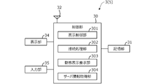
図10は、管理者端末3の概略構成を示すブロック図である。図10に示すように、管理者端末3は、制御部30と、記憶部31と、通信部32と、表示部34と、入力部35とを有する。
記憶部31は、半導体メモリやハードディスクドライブ等で構成される。記憶部31には、オペレーティングシステム(OS)やアプリケーションと呼ばれるソフトウェアや、その他の種々の情報が記憶される。記憶部31に記憶されるソフトウェアには、ポスティングや配達の作業を管理するためのアプリケーションプログラムが含まれる。
通信部32は、有線通信(例えば、インターネット回線等)または3G、LTE、4G、5G等の無線通信をすることができる通信プロトコルを実装し、管理サーバ2と接続して送受信する。
表示部34は、液晶ディスプレイまたは有機ELパネル等の表示デバイスにより構成され、制御部30からの指示を受けて、地図やタッチパネル用の操作ボタンのアイコン等を表示する。さらに表示部34は、管理サーバ2の情報出力部207から送信された画像信号に基づいて各種画像を表示する。
入力部35は、管理者によって操作されるテンキーなどの物理スイッチや、表示部34の表示面に重ねて設けられたタッチパネル等の入力装置(図示せず)などで構成される。入力部35を介して、表示部34の表示画面の切替え指令が入力される。各配達グループの担当エリアの設定(配達先の仕分け)は、入力部35を介して行うことができる。
制御部30は、CPU、RAM、ROM、I/O等を有するプロセッサを含んで構成される。制御部30は、機能的構成として、表示制御部301と、接続処理部302と、動態表示要求部303と、サーバ情報取得部304とを有する。
表示制御部301は、入力部35の操作に応じて画像信号を生成して表示部34に送信することで、表示部34による画面表示を制御する。表示制御部301が表示部34に表示させる画面には、動態表示システム100にログインするためのログイン画面、各配達グループの担当エリアを設定する設定画面などが含まれる。
接続処理部302は、例えば、配送拠点の管理者または責任者を識別する識別番号(拠点管理者ID)およびパスワードを用いて、管理サーバ2に対してログイン処理を実行する。
動態表示要求部303は、管理者による入力部35の操作に応じて、動態画像DP1を表示するための画像信号の出力要求(指令)を管理サーバ2に送信する。例えば、接続処理部302によりログイン処理が実行されると、同時に、動態画像DP1を表示するための画像信号の出力要求を管理サーバ2に送信する。
サーバ情報取得部304は、管理サーバ2(情報出力部207)から送信された画像信号等を取得する。サーバ情報取得部304により画像信号が取得されると、表示部34に各種画像(図4、図5、図7A~図8)が表示される。
[動態表示システム100の動作]
次に、動態表示システム100の動作の一例について説明する。車両6A,6Bを運転する配達員A,Bは、それぞれ、例えば配送拠点から出発する際、すなわち始業時に、配達員端末1A,1Bの表示部14に表示されるログイン画面上で、入力部15を介して自身のログインID及びパスワードを入力する。この入力がなされると、管理サーバ2は、配達員端末1A,1Bとの接続処理を行う。
次に、動態表示システム100の動作の一例について説明する。車両6A,6Bを運転する配達員A,Bは、それぞれ、例えば配送拠点から出発する際、すなわち始業時に、配達員端末1A,1Bの表示部14に表示されるログイン画面上で、入力部15を介して自身のログインID及びパスワードを入力する。この入力がなされると、管理サーバ2は、配達員端末1A,1Bとの接続処理を行う。
その後、配達員端末1A、1Bは、所定の時間間隔(例えば1秒間隔)で管理サーバ2と通信し、配達員A,Bまたは車両6A、6Bの位置情報を管理サーバ2に送信する。配達員端末1A、1Bと管理サーバ2との通信は、配達員端末1A,1Bがログアウト操作するまで継続される。
一方、配送拠点の管理者は、管理者端末3のタッチパネル(入力部35)を操作してポスティングや配達の作業を管理するためのアプリケーションプログラムを起動し、表示部34に表示されるログイン画面上で拠点管理者IDおよびパスワードを入力する。この入力がなされると、管理サーバ2は、管理者端末3との接続処理を行う。
管理サーバ2は、管理者端末3からの指令に応じて、拠点管理者IDに対応する配達員の現在位置Pを表示する動態画像DP1およびメニューDP2の画像信号を生成して管理者端末3に送信する。配送拠点の管理者が表示部34に表示されるメニューDP2の自動切替ボタンBT1を押下して自動切替機能をオンにすると、配達グループごとの動態画像DP1が自動的に、順次、切り替えて表示される(図9のステップS1~S6)(図4、図5、図7A~図8)。
これにより配送拠点の管理者は、管理対象の配達員の動態を良好な態様で確認することができる。管理対象となる配達員の人数や密集度によっては、図4に示すように、すべての配達員の現在位置を一度に表示すると地図が広域表示となり、各配達員の現在位置を示す位置アイコンPI同士が重なるなどして個々の配達員の現在位置や動きを把握することが難しい。
一方、個々の配達員の現在位置や動きを把握できるよう、管理者であるユーザ自身が図5、図7A~図8に示すような地図の縮尺や中心位置になるよう操作するのは、ユーザにとって煩雑となる。この点、動態表示装置5では、図5、図7A~図8あるいは図4、図5、図7A~図8の表示モードを自動的に切り替えて動態画像DP1が表示されるため、管理者は、時々刻々と変化する配達員の動態を多面的に把握することができる。
複数のグループに所属する配達員の動態を多面的に把握するには、複数の表示モードの画面表示DPをマルチディスプレイ表示することもできるが、この場合は個々の画面表示DPが小さくなる、あるいは表示部34として大型のディスプレイが必要となる。この点、動態表示装置5では、表示モードを適宜な時間間隔で自動的に切り替えて動態画像DP1が表示されるため、例えば表示部34がタブレット端末等の比較的小型のディスプレイであっても、時々刻々と変化する配達員の動態を多面的に把握することができる。
本実施形態によれば以下のような作用効果を奏することができる。
(1)動態表示装置5は、複数の配達グループ1~3のいずれかに属する複数の配達員の現在位置Pをリアルタイムで表示する(図4、図5、図7A~図8)。動態表示装置5は、複数の配達員のそれぞれの位置情報を取得する位置情報取得部202と、表示部34と、位置情報取得部202により取得された位置情報に基づいて、地図画像MAP上に配達員の現在位置Pを示す位置アイコンPIをリアルタイムで表示するように表示部34を制御する表示制御部203とを備える(図3、図10)。
(1)動態表示装置5は、複数の配達グループ1~3のいずれかに属する複数の配達員の現在位置Pをリアルタイムで表示する(図4、図5、図7A~図8)。動態表示装置5は、複数の配達員のそれぞれの位置情報を取得する位置情報取得部202と、表示部34と、位置情報取得部202により取得された位置情報に基づいて、地図画像MAP上に配達員の現在位置Pを示す位置アイコンPIをリアルタイムで表示するように表示部34を制御する表示制御部203とを備える(図3、図10)。
表示制御部203は、配達グループ1~3に属する配達員の位置アイコンPIをリアルタイムで表示する第1~第3グループ表示モードを含む複数の表示モードを所定の時間間隔で切り替える表示モード切替部204を有する(図3)。これにより複数の配達員の現在位置がグループごとに表示されるため、配送拠点の管理者は、良好な態様で全ての配達員の現在位置を把握できるとともに、各配達員の現在の状況を詳細に把握することができる。
すなわち、グループごとに動態表示を行うことで、地図が広域になり過ぎることを抑制することができ、管理者にとって見やすい画面表示とすることができる。また、グループごとの表示が自動的に切り替えられるため、管理者は地図の縮尺や表示位置の調整操作を行う必要がなく、動態の把握に集中することができる。
(2)動態表示装置5は、配送拠点の管理者からの指令を受け付ける入力部35をさらに備える(図10)。表示制御部203は、入力部35により受け付けられた指令に応じて、表示モード切替部204による表示モードの切替を停止する。これにより、必要に応じて自動切替を停止できるため、注目したい配達グループや配達員がいる場合や、注目したいエリアがある場合でも、良好な態様で配達員の動きを把握することができる。
(3)入力部35は、表示部34に押下可能に表示される自動切替ボタンBT1が管理者により押下されたことを契機として管理者からの指令を受け付ける。表示部34上で管理者により操作可能な自動切替ボタンBT1を設けることで、管理者は、必要に応じ、簡易な操作で表示モードの自動切替を停止することができる。
(4)入力部35は、表示部34に選択可能に表示される複数の配達グループ1~3のそれぞれに対応した複数の地図表示ボタンBT61~BT63のいずれかが管理者により選択されたことを契機として管理者からの指令を受け付ける。表示モード切替部204は、管理者により選択された配達グループを表示するように表示モードを切り替える。表示制御部203は、入力部35により受け付けられた指令に応じて、表示モード切替部204による表示モードの切替を停止する。
これにより管理者は、簡易な操作で迅速に、注目したい配達グループごとの表示モードに切り替えることができる。また、管理者による操作により表示モードが切り替えられると表示モードの自動切替が停止されるため、管理者が注目している配達グループの表示が自動的に切り替えられることがなく、管理者の意図に沿った画面表示を提供することができる。
(5)地図画像MAPは、縮尺および位置を変更する操作可能に、表示部34に表示される。入力部35は、地図画像MAPが管理者により操作されたことを契機として管理者からの指令を受け付ける。表示制御部203は、入力部35により受け付けられた指令に応じて、表示モード切替部204による表示モードの切替を停止する。
管理者による操作により地図画像MAPの縮尺や位置を変更する操作が行われると表示モードの自動切替が停止されるため、管理者が注目している地図の表示が自動的に切り替えられることがなく、管理者の意図に沿った画面表示を提供することができる。
(6)表示制御部203は、表示モード切替部204により表示モードが第1~第3グループ表示モードに切り替えられると、位置情報取得部202により位置情報が取得された配達グループ1~3に属する全ての配達員の位置アイコンPIをリアルタイムで表示するように表示部34を制御する。
これにより、例えば図7Bに示すように同一の配達グループ内の配達員が分散しているような場合でも、同一の配達グループ内の全てのログイン状態の配達員の現在位置が自動的に表示されるため、各配達グループの状況を的確に把握することができる。例えば、配達員が通常とは異なる場所に移動しているような場合には、地図の縮尺や表示位置が通常とは異なる状態になるため、通常と異なる状況を容易に認識することができる。
(7)表示モード切替部204は、複数の配達グループ1~3を同時に表示する全グループ表示モードをさらに含む複数の表示モードを所定の時間間隔で切り替える。これにより、配達グループ同士の位置関係を把握するとともに、個々の配達員の動態も把握することができる。このため、全体の動態を俯瞰した後に部分の動態を確認することで、配達員の状況を容易に把握できるとともに、配達員の動きを一層多面的に把握することができる。
(8)表示制御部203は、表示モード切替部204により表示モードが第1~第3グループ表示モードに切り替えられると、各配達グループ1~3に対して予め設定された担当エリア内に位置する配達員の位置アイコンPIをリアルタイムで表示するように表示部34を制御する。
これにより、各配達グループに割り当てられた担当エリアにおける配達員の動きを的確に把握することができる。すなわち、常に、予め各配達グループに割り当てられた担当エリアが表示されるため、地図画像から表示中の配達グループを容易に認識することができる。また、注目したいエリア内の配達員の人数や動きを容易に把握することができる。
(9)動態表示装置5は、位置情報取得部202により取得された位置情報に基づいて、配達員が所定範囲内に所定時間以上滞在している滞留状態であるか否かを判定する滞留判定部205をさらに備える(図3)。表示制御部203は、滞留判定部205により滞留状態であると判定された配達員の位置アイコンPIを他の配達員の位置アイコンPIとは識別可能な態様で表示する。あるいは、滞留判定部205により滞留状態であると判定された配達員について警告する滞留警告画像を表示するように表示部34を制御する。
各配達員が配達のために想定される時間を超えて1箇所に滞在している状態を認識可能な態様で表示することで、配達中のトラブル等の異常事態を早期に発見することができる。
(10)動態表示装置5は、配達員が、所定時間以上、位置情報取得部202により位置情報の取得が不能な通信不能状態であるか否かを判定する通信不能判定部206をさらに備える(図3)。表示制御部203は、通信不能判定部206により通信不能状態であると判定された配達員の位置アイコンPIを他の配達員の位置アイコンPIとは識別可能な態様で表示するように表示部34を制御する。これにより、配達員端末1A,1Bの故障等を早期に発見することができる。
なお、上記実施形態は種々の形態に変形することができる。以下、変形例について説明する。上記実施形態では、動態表示装置5により、ポスティングや配達の作業を行う配達員の動きをリアルタイムで表示する例を説明したが、動態表示装置は複数のグループのいずれかに属する複数の表示対象の現在位置をリアルタイムで表示するものであれば、どのようなものでもよい。例えば、大型施設の来場者の動きを、来場者のグループごと、あるいは滞在中のエリアごとにリアルタイムで表示してもよい。
上記実施形態では、位置情報取得部202が配達員端末1A,1B側で算出された位置情報を取得するようにしたが、表示対象の位置情報を取得する位置情報取得部の構成はこれに限らない。例えば、配達員端末1A,1B側で受信されたGPS信号等に基づいて、管理サーバ2で位置を算出するようにしてもよい。
上記実施形態では、管理者端末3の表示部34に設けられたタッチパネルやマウス等により管理者であるユーザからの指令を受け付けるとしたが、ユーザからの指令を受け付ける指令受付部はこのようなものに限らない。例えば、管理者端末3にマイクを設けてユーザの音声による指令を受け付けてもよく、管理者端末3にカメラを設けてユーザのジェスチャによる指令を受け付けてもよい。
上記実施形態では、管理サーバ2の表示制御部203が管理者端末3の表示部34を制御するとしたが、表示部を制御する表示制御部はこれに限らない。すなわち、管理者端末3の表示制御部301が図4、図5、図7A~図8に示すような画面表示DPの画像信号を生成してもよい。
以上では、本発明を動態表示装置5として説明したが、本発明は、複数のグループのいずれかに属する複数の表示対象の現在位置をリアルタイムで表示する動態表示方法として用いることもできる。すなわち、動態表示方法は、複数の配達員のそれぞれの位置情報を取得し(図9のステップS3,S4)、取得した位置情報に基づいて、地図画像MAP上に配達員の現在位置Pを示す位置アイコンPIをリアルタイムで表示するように表示部34を制御し(ステップS5,S6)、配達グループ1~3に属する配達員の位置アイコンPIをリアルタイムで表示する第1~第3グループ表示モードを含む複数の表示モードを所定の時間間隔で切り替える(ステップS1、S2)ことを含む。
以上では、動態表示プログラムを管理サーバ2の記憶部21に格納したが、フラッシュメモリ等の外部記憶媒体に格納してもよい。ネットワーク4を介して動態表示システム100の外部から動態表示プログラムを取得することもできる。
以上の説明はあくまで一例であり、本発明の特徴を損なわない限り、上述した実施形態および変形例により本発明が限定されるものではない。上記実施形態と変形例の1つまたは複数を任意に組み合わせることも可能であり、変形例同士を組み合わせることも可能である。
1A,1B 配達員端末、2 管理サーバ、3 管理者端末、4 ネットワーク、5 動態表示装置、6A,6B 車両、10 制御部、11 記憶部、12 無線部、13 センサ部、13a GPSセンサ、13b ジャイロセンサ、14 表示部、15 入力部、20 制御部、21 記憶部、22 通信部、24 表示部、25 入力部、30 制御部、31 記憶部、32 通信部、34 表示部、35 入力部、100 動態表示システム、101 表示制御部、102 接続処理部、103 位置情報通知部、201 接続処理部、202 位置情報取得部、203 表示制御部、204 表示モード切替部、205 滞留判定部、206 通信不能判定部、207 情報出力部、211 配達員情報エリア、212 車両情報エリア、213 配達先情報エリア、214 地図情報エリア、301 表示制御部、302 接続処理部、303 動態表示要求部、304 サーバ情報取得部
Claims (13)
- 第1グループと第2グループとを含む複数のグループのいずれかに属する複数の表示対象の現在位置をリアルタイムで表示する動態表示装置であって、
前記複数の表示対象のそれぞれの位置情報を取得する位置情報取得部と、
表示部と、
前記位置情報取得部により取得された位置情報に基づいて、地図画像上に前記表示対象の現在位置を示すアイコン画像をリアルタイムで表示するように前記表示部を制御する表示制御部と、を備え、
前記表示制御部は、前記第1グループに属する表示対象の前記アイコン画像をリアルタイムで表示する第1グループ表示モードと、前記第2グループに属する表示対象の前記アイコン画像をリアルタイムで表示する第2グループ表示モードと、を含む複数の表示モードを所定の時間間隔で切り替える表示モード切替部を有することを特徴とする動態表示装置。 - 請求項1に記載の動態表示装置において、
ユーザからの指令を受け付ける指令受付部をさらに備え、
前記表示制御部は、前記指令受付部により受け付けられた指令に応じて、前記表示モード切替部による表示モードの切替を停止することを特徴とする動態表示装置。 - 請求項2に記載の動態表示装置において、
前記指令受付部は、前記表示部に押下可能に表示されるボタン画像がユーザにより押下されたことを契機としてユーザからの指令を受け付けることを特徴とする動態表示装置。 - 請求項2または3に記載の動態表示装置において、
前記指令受付部は、前記表示部に選択可能に表示される前記複数のグループのそれぞれに対応した複数のボタン画像のいずれかがユーザにより選択されたことを契機としてユーザからの指令を受け付け、
前記表示モード切替部は、ユーザにより選択されたグループを表示するように前記表示モードを切り替え、
前記表示制御部は、前記指令受付部により受け付けられた指令に応じて、前記表示モード切替部による表示モードの切替を停止することを特徴とする動態表示装置。 - 請求項2~4のいずれか1項に記載の動態表示装置において、
前記地図画像は、縮尺および位置を変更する操作可能に、前記表示部に表示され、
前記指令受付部は、前記地図画像がユーザにより操作されたことを契機としてユーザからの指令を受け付け、
前記表示制御部は、前記指令受付部により受け付けられた指令に応じて、前記表示モード切替部による表示モードの切替を停止することを特徴とする動態表示装置。 - 請求項1~5のいずれか1項に記載の動態表示装置において、
前記表示制御部は、前記表示モード切替部により表示モードが前記第1グループ表示モードに切り替えられると、前記位置情報取得部により位置情報が取得された前記第1グループに属する全ての表示対象の前記アイコン画像をリアルタイムで表示し、前記表示モード切替部により表示モードが前記第2グループ表示モードに切り替えられると、前記位置情報取得部により位置情報が取得された前記第2グループに属する全ての表示対象の前記アイコン画像をリアルタイムで表示するように前記表示部を制御することを特徴とする動態表示装置。 - 請求項6に記載の動態表示装置において、
前記表示モード切替部は、前記複数のグループを同時に表示する全グループ表示モードをさらに含む前記複数の表示モードを所定の時間間隔で切り替えることを特徴とする動態表示装置。 - 請求項1~7のいずれか1項に記載の動態表示装置において、
前記表示制御部は、前記表示モード切替部により表示モードが前記第1グループ表示モードに切り替えられると、前記第1グループに対して予め設定された第1エリア内に位置する表示対象の前記アイコン画像をリアルタイムで表示し、前記表示モード切替部により表示モードが前記第2グループ表示モードに切り替えられると、前記第2グループに対して予め設定された第2エリア内に位置する表示対象の前記アイコン画像をリアルタイムで表示するように前記表示部を制御することを特徴とする動態表示装置。 - 請求項1~8のいずれか1項に記載の動態表示装置において、
前記位置情報取得部により取得された位置情報に基づいて、前記表示対象が所定範囲内に所定時間以上滞在している滞留状態であるか否かを判定する滞留判定部をさらに備え、
前記表示制御部は、前記滞留判定部により前記滞留状態であると判定された表示対象の前記アイコン画像を他の表示対象の前記アイコン画像とは識別可能な態様で表示する、あるいは、前記滞留判定部により前記滞留状態であると判定された表示対象について警告する滞留警告画像を表示するように前記表示部を制御することを特徴とする動態表示装置。 - 請求項1~9のいずれか1項に記載の動態表示装置において、
前記表示対象が、所定時間以上、前記位置情報取得部により位置情報の取得が不能な通信不能状態であるか否かを判定する通信不能判定部をさらに備え、
前記表示制御部は、前記通信不能判定部により前記通信不能状態であると判定された表示対象の前記アイコン画像を他の表示対象の前記アイコン画像とは識別可能な態様で表示するように前記表示部を制御することを特徴とする動態表示装置。 - 請求項1~10のいずれか1項に記載の動態表示装置と、
前記表示対象とともに移動し、前記表示対象の位置情報を前記動態表示装置に送信する移動端末と、を備えることを特徴とする動態表示システム。 - 第1グループと第2グループとを含む複数のグループのいずれかに属する複数の表示対象の現在位置をリアルタイムで表示する動態表示方法であって、
前記複数の表示対象のそれぞれの位置情報を取得し、
取得した位置情報に基づいて、地図画像上に前記表示対象の現在位置を示すアイコン画像をリアルタイムで表示するように表示部を制御し、
前記第1グループに属する表示対象の前記アイコン画像をリアルタイムで表示する第1グループ表示モードと、前記第2グループに属する表示対象の前記アイコン画像をリアルタイムで表示する第2グループ表示モードと、を含む複数の表示モードを所定の時間間隔で切り替えることを含む動態表示方法。 - 第1グループと第2グループとを含む複数のグループのいずれかに属する複数の表示対象の現在位置をリアルタイムで表示する動態表示プログラムであって、
前記複数の表示対象のそれぞれの位置情報を取得する手順と、
取得した位置情報に基づいて、地図画像上に前記表示対象の現在位置を示すアイコン画像をリアルタイムで表示するように表示部を制御する手順と、
前記第1グループに属する表示対象の前記アイコン画像をリアルタイムで表示する第1グループ表示モードと、前記第2グループに属する表示対象の前記アイコン画像をリアルタイムで表示する第2グループ表示モードと、を含む複数の表示モードを所定の時間間隔で切り替える手順と、をコンピュータに実行させるための動態表示プログラム。
Priority Applications (5)
| Application Number | Priority Date | Filing Date | Title |
|---|---|---|---|
| CN201880099628.8A CN113168786A (zh) | 2018-11-22 | 2018-11-22 | 动态显示装置、动态显示系统、动态显示方法以及动态显示程序 |
| PCT/JP2018/043284 WO2020105193A1 (ja) | 2018-11-22 | 2018-11-22 | 動態表示装置、動態表示システム、動態表示方法および動態表示プログラム |
| JP2020557402A JP7169367B2 (ja) | 2018-11-22 | 2018-11-22 | 動態表示装置、動態表示システム、動態表示方法および動態表示プログラム |
| CN202310425210.4A CN116884308A (zh) | 2018-11-22 | 2018-11-22 | 动态显示装置、动态显示系统、动态显示方法以及动态显示程序 |
| TW108139429A TW202036501A (zh) | 2018-11-22 | 2019-10-31 | 動態顯示裝置、動態顯示系統、動態顯示方法及動態顯示程式 |
Applications Claiming Priority (1)
| Application Number | Priority Date | Filing Date | Title |
|---|---|---|---|
| PCT/JP2018/043284 WO2020105193A1 (ja) | 2018-11-22 | 2018-11-22 | 動態表示装置、動態表示システム、動態表示方法および動態表示プログラム |
Publications (1)
| Publication Number | Publication Date |
|---|---|
| WO2020105193A1 true WO2020105193A1 (ja) | 2020-05-28 |
Family
ID=70774513
Family Applications (1)
| Application Number | Title | Priority Date | Filing Date |
|---|---|---|---|
| PCT/JP2018/043284 Ceased WO2020105193A1 (ja) | 2018-11-22 | 2018-11-22 | 動態表示装置、動態表示システム、動態表示方法および動態表示プログラム |
Country Status (4)
| Country | Link |
|---|---|
| JP (1) | JP7169367B2 (ja) |
| CN (2) | CN116884308A (ja) |
| TW (1) | TW202036501A (ja) |
| WO (1) | WO2020105193A1 (ja) |
Cited By (1)
| Publication number | Priority date | Publication date | Assignee | Title |
|---|---|---|---|---|
| JP7745350B2 (ja) | 2021-02-16 | 2025-09-29 | ヤンマーホールディングス株式会社 | 表示方法、表示端末、及び表示プログラム |
Citations (3)
| Publication number | Priority date | Publication date | Assignee | Title |
|---|---|---|---|---|
| JP2014048683A (ja) * | 2012-08-29 | 2014-03-17 | Seikou Trans Network Co Ltd | 情報選択支援システム、情報選択支援サーバ、情報選択支援方法およびプログラム |
| WO2015159602A1 (ja) * | 2014-04-18 | 2015-10-22 | Necソリューションイノベータ株式会社 | 情報提供装置 |
| JP2017095263A (ja) * | 2015-11-26 | 2017-06-01 | 株式会社東芝 | 輸送物監視システムおよび輸送物監視方法 |
Family Cites Families (7)
| Publication number | Priority date | Publication date | Assignee | Title |
|---|---|---|---|---|
| JP2003223699A (ja) * | 2001-11-26 | 2003-08-08 | Shosuke Ozuru | 移動体ネットワークを使用した車両情報管理方法およびシステム |
| JP2003316865A (ja) * | 2002-04-24 | 2003-11-07 | Fujitsu Ten Ltd | 車両動態管理方法およびシステム |
| JP2004233094A (ja) * | 2003-01-28 | 2004-08-19 | Krs:Kk | 配達支援装置、配達支援プログラム及び運行管理システム |
| JP2012008222A (ja) * | 2010-06-22 | 2012-01-12 | Olympus Imaging Corp | 表示装置 |
| KR20160071202A (ko) * | 2014-12-11 | 2016-06-21 | 태상로지스틱스(주) | 효율적인 물류배송 관리 시스템 및 물류배송 관리 방법 |
| JP2018124900A (ja) * | 2017-02-03 | 2018-08-09 | 本田技研工業株式会社 | 運転管理装置、運転管理方法および運転管理システム |
| JP6822873B2 (ja) * | 2017-03-02 | 2021-01-27 | 本田技研工業株式会社 | 配達管理装置、配達管理方法および配達管理システム |
-
2018
- 2018-11-22 JP JP2020557402A patent/JP7169367B2/ja active Active
- 2018-11-22 CN CN202310425210.4A patent/CN116884308A/zh active Pending
- 2018-11-22 WO PCT/JP2018/043284 patent/WO2020105193A1/ja not_active Ceased
- 2018-11-22 CN CN201880099628.8A patent/CN113168786A/zh active Pending
-
2019
- 2019-10-31 TW TW108139429A patent/TW202036501A/zh unknown
Patent Citations (3)
| Publication number | Priority date | Publication date | Assignee | Title |
|---|---|---|---|---|
| JP2014048683A (ja) * | 2012-08-29 | 2014-03-17 | Seikou Trans Network Co Ltd | 情報選択支援システム、情報選択支援サーバ、情報選択支援方法およびプログラム |
| WO2015159602A1 (ja) * | 2014-04-18 | 2015-10-22 | Necソリューションイノベータ株式会社 | 情報提供装置 |
| JP2017095263A (ja) * | 2015-11-26 | 2017-06-01 | 株式会社東芝 | 輸送物監視システムおよび輸送物監視方法 |
Cited By (1)
| Publication number | Priority date | Publication date | Assignee | Title |
|---|---|---|---|---|
| JP7745350B2 (ja) | 2021-02-16 | 2025-09-29 | ヤンマーホールディングス株式会社 | 表示方法、表示端末、及び表示プログラム |
Also Published As
| Publication number | Publication date |
|---|---|
| TW202036501A (zh) | 2020-10-01 |
| JPWO2020105193A1 (ja) | 2021-10-28 |
| JP7169367B2 (ja) | 2022-11-10 |
| CN116884308A (zh) | 2023-10-13 |
| CN113168786A (zh) | 2021-07-23 |
Similar Documents
| Publication | Publication Date | Title |
|---|---|---|
| WO2020066771A1 (ja) | 依頼処理システム | |
| US10171982B2 (en) | Emergency evacuation service | |
| CN103918285A (zh) | 向移动设备传递动态疏散信息 | |
| JP7046195B2 (ja) | 運転評価装置 | |
| JP2017116998A (ja) | 情報処理装置、情報処理システム、情報処理方法、情報処理プログラム | |
| JPWO2020110215A1 (ja) | 経路評価装置、経路評価システム、経路評価方法および経路評価プログラム | |
| WO2020031827A1 (ja) | 運転評価装置 | |
| JP2021006958A (ja) | 配車管理装置及びプログラム | |
| US10635376B2 (en) | Client and program | |
| WO2020105193A1 (ja) | 動態表示装置、動態表示システム、動態表示方法および動態表示プログラム | |
| US20180098367A1 (en) | System and method for proximity based pairing and information exchange between mobile devices | |
| JP7035197B2 (ja) | 訪問管理装置、訪問管理方法および訪問管理システム | |
| JP7019057B2 (ja) | 経路細分装置 | |
| JP7022041B2 (ja) | 画像選択装置 | |
| TWI750524B (zh) | 作業成果視覺化裝置、作業成果視覺化系統、作業成果視覺化方法及作業成果視覺化程式 | |
| CN110969788A (zh) | 个人化逃生导引系统 | |
| JP2012044340A (ja) | 通信指令装置 | |
| CN109246616B (zh) | 一种提醒方法和装置 | |
| JP2024091696A (ja) | 自動車競技向けユーザインターフェースの提供方法 | |
| TW202011217A (zh) | 個人化逃生導引系統 | |
| JP2004166020A (ja) | 情報サービスシステム |
Legal Events
| Date | Code | Title | Description |
|---|---|---|---|
| 121 | Ep: the epo has been informed by wipo that ep was designated in this application |
Ref document number: 18940480 Country of ref document: EP Kind code of ref document: A1 |
|
| ENP | Entry into the national phase |
Ref document number: 2020557402 Country of ref document: JP Kind code of ref document: A |
|
| NENP | Non-entry into the national phase |
Ref country code: DE |
|
| 122 | Ep: pct application non-entry in european phase |
Ref document number: 18940480 Country of ref document: EP Kind code of ref document: A1 |