WO2020105177A1 - 冷凍サイクル装置 - Google Patents
冷凍サイクル装置Info
- Publication number
- WO2020105177A1 WO2020105177A1 PCT/JP2018/043231 JP2018043231W WO2020105177A1 WO 2020105177 A1 WO2020105177 A1 WO 2020105177A1 JP 2018043231 W JP2018043231 W JP 2018043231W WO 2020105177 A1 WO2020105177 A1 WO 2020105177A1
- Authority
- WO
- WIPO (PCT)
- Prior art keywords
- refrigerant
- refrigeration cycle
- refrigerant pipe
- housing
- valve
- Prior art date
- Legal status (The legal status is an assumption and is not a legal conclusion. Google has not performed a legal analysis and makes no representation as to the accuracy of the status listed.)
- Ceased
Links
Images



Classifications
-
- F—MECHANICAL ENGINEERING; LIGHTING; HEATING; WEAPONS; BLASTING
- F25—REFRIGERATION OR COOLING; COMBINED HEATING AND REFRIGERATION SYSTEMS; HEAT PUMP SYSTEMS; MANUFACTURE OR STORAGE OF ICE; LIQUEFACTION SOLIDIFICATION OF GASES
- F25B—REFRIGERATION MACHINES, PLANTS OR SYSTEMS; COMBINED HEATING AND REFRIGERATION SYSTEMS; HEAT PUMP SYSTEMS
- F25B41/00—Fluid-circulation arrangements
- F25B41/20—Disposition of valves, e.g. of on-off valves or flow control valves
- F25B41/24—Arrangement of shut-off valves for disconnecting a part of the refrigerant cycle, e.g. an outdoor part
-
- F—MECHANICAL ENGINEERING; LIGHTING; HEATING; WEAPONS; BLASTING
- F24—HEATING; RANGES; VENTILATING
- F24F—AIR-CONDITIONING; AIR-HUMIDIFICATION; VENTILATION; USE OF AIR CURRENTS FOR SCREENING
- F24F1/00—Room units for air-conditioning, e.g. separate or self-contained units or units receiving primary air from a central station
- F24F1/06—Separate outdoor units, e.g. outdoor unit to be linked to a separate room comprising a compressor and a heat exchanger
- F24F1/26—Refrigerant piping
- F24F1/32—Refrigerant piping for connecting the separate outdoor units to indoor units
-
- F—MECHANICAL ENGINEERING; LIGHTING; HEATING; WEAPONS; BLASTING
- F24—HEATING; RANGES; VENTILATING
- F24F—AIR-CONDITIONING; AIR-HUMIDIFICATION; VENTILATION; USE OF AIR CURRENTS FOR SCREENING
- F24F11/00—Control or safety arrangements
- F24F11/30—Control or safety arrangements for purposes related to the operation of the system, e.g. for safety or monitoring
- F24F11/32—Responding to malfunctions or emergencies
- F24F11/36—Responding to malfunctions or emergencies to leakage of heat-exchange fluid
-
- F—MECHANICAL ENGINEERING; LIGHTING; HEATING; WEAPONS; BLASTING
- F25—REFRIGERATION OR COOLING; COMBINED HEATING AND REFRIGERATION SYSTEMS; HEAT PUMP SYSTEMS; MANUFACTURE OR STORAGE OF ICE; LIQUEFACTION SOLIDIFICATION OF GASES
- F25B—REFRIGERATION MACHINES, PLANTS OR SYSTEMS; COMBINED HEATING AND REFRIGERATION SYSTEMS; HEAT PUMP SYSTEMS
- F25B41/00—Fluid-circulation arrangements
-
- F—MECHANICAL ENGINEERING; LIGHTING; HEATING; WEAPONS; BLASTING
- F25—REFRIGERATION OR COOLING; COMBINED HEATING AND REFRIGERATION SYSTEMS; HEAT PUMP SYSTEMS; MANUFACTURE OR STORAGE OF ICE; LIQUEFACTION SOLIDIFICATION OF GASES
- F25B—REFRIGERATION MACHINES, PLANTS OR SYSTEMS; COMBINED HEATING AND REFRIGERATION SYSTEMS; HEAT PUMP SYSTEMS
- F25B49/00—Arrangement or mounting of control or safety devices
- F25B49/02—Arrangement or mounting of control or safety devices for compression type machines, plants or systems
Definitions
- the present invention relates to a refrigeration cycle device designed to suppress refrigerant leakage.
- the refrigeration cycle device needs to prevent the refrigerant from leaking to the outside of the refrigeration cycle device depending on the refrigerant used.
- F gas hydrofluorocarbon
- PFC perfluorocarbon
- SF6 sulfur hexafluoride
- R410A refrigerant instead of a non-combustible refrigerant R410A refrigerant that is a type of HFC refrigerant, a flammable refrigerant such as R32 refrigerant having a global warming potential smaller than R410A is used. May be used.
- a conventional air conditioner includes a detection sensor that detects leakage of the refrigerant to the living space and a shutoff valve that shuts off the circulation of the refrigerant in the refrigeration cycle circuit (Patent Document 1).
- the conventional air conditioner includes an outdoor unit, a plurality of indoor units that are usage-side units, and a plurality of relay units that connect the outdoor unit and the indoor units.
- the conventional air conditioner includes a detection sensor in the indoor unit that detects leakage of the refrigerant.
- the relay unit includes a shutoff valve that shuts off the circulation of the refrigerant in the refrigeration cycle circuit. Then, in the conventional air conditioner, when the detection sensor detects the leakage of the refrigerant to the living space, the cutoff valve of the relay unit cuts off the circulation of the refrigerant in the refrigeration cycle circuit, and the refrigerant leaks to the living space. It is restrained.
- the relay unit is installed in the space around the living space inside the building, such as in the ceiling. Therefore, it may not be possible to secure the installation space for the relay unit in the building. Further, even if the installation space for the relay unit can be secured in the building, it is difficult to secure a large installation space for the relay unit, and the shutoff valve may not be provided in the relay unit. As described above, the conventional refrigeration cycle apparatus has a problem in that it is difficult to install the shutoff valve that shuts off the circulation of the refrigerant in the refrigeration cycle circuit.
- the present invention has been made to solve the above problems, and an object of the present invention is to obtain a refrigeration cycle apparatus in which a shutoff valve that shuts off the circulation of the refrigerant in the refrigeration cycle circuit is installed more easily than in the past. ..
- a refrigeration cycle apparatus has a plurality of constituent devices, a plurality of the constituent devices are connected by a refrigerant pipe, a refrigeration cycle circuit configured, and a part of the plurality of constituent devices is housed.
- a refrigeration cycle apparatus comprising: an outdoor unit having a housing; and a use-side unit in which a part of the plurality of constituent devices is housed, the housing being housed in the housing of the outdoor unit.
- the refrigerant pipe through which the gaseous refrigerant or the refrigerant in the supercritical state flows is the first refrigerant pipe
- the outdoor unit is Among the refrigerant pipes that connect the constituent device housed in the housing and the constituent device housed in the usage-side unit, the refrigerant pipe in which a liquid refrigerant or a refrigerant in a gas-liquid two-phase state flows is the second refrigerant.
- a detection sensor for detecting the refrigerant leaked from the refrigeration cycle circuit a first shutoff valve provided in the middle of the first refrigerant pipe, and a middle of the second refrigerant pipe are provided.
- the first cutoff valve is closed to cut off the flow of the refrigerant in the first refrigerant pipe
- a control device that closes a second shutoff valve to shut off the flow of the refrigerant in the second refrigerant pipe, and the first shutoff valve and the second shutoff valve are housed and arranged outside the housing of the outdoor unit. And a storage box that is attached to the housing.
- the installation space for the outdoor unit is larger and easier to secure than the installation space for the relay unit. Therefore, in the refrigeration cycle apparatus according to the present invention, it is easier to install the first shutoff valve and the second shutoff valve, which are shutoff valves for shutting off the circulation of the refrigerant in the refrigeration cycle circuit, as compared with the related art.
- FIG. 1 is a refrigerant circuit diagram showing a refrigeration cycle device according to an embodiment of the present invention.
- the refrigeration cycle device 1 according to the present embodiment includes a refrigeration cycle circuit 10 in which a refrigerant circulates.
- the refrigeration cycle circuit 10 has a plurality of constituent devices, and the plurality of constituent devices are connected by a refrigerant pipe.
- the refrigeration cycle circuit 10 is an example of a compressor 11, a four-way valve 12, an outdoor heat exchanger 13, an expansion valve 14, and a utilization side heat exchanger, as constituent devices of the refrigeration cycle circuit 10.
- the indoor heat exchanger 15 is provided.
- the compressor 11 compresses the sucked low-pressure gaseous refrigerant and discharges it as high-pressure gaseous refrigerant.
- refrigerant such as carbon dioxide refrigerant that is discharged from the compressor 11 as a refrigerant in a supercritical state.
- the four-way valve 12 is a valve that switches the flow of the refrigerant between the cooling operation and the heating operation.
- the indoor heat exchanger 15 which is the usage-side heat exchanger, functions as a radiator during heating operation and functions as an evaporator during cooling operation. Therefore, the refrigeration cycle circuit 10 includes the four-way valve 12.
- the refrigeration cycle circuit 10 may not include the four-way valve 12 when the use-side heat exchanger needs to function only as one of the radiator and the evaporator.
- the outdoor heat exchanger 13 exchanges heat between the refrigerant and the outdoor air.
- the outdoor heat exchanger 13 functions as an evaporator during the heating operation, and evaporates and evaporates the refrigerant. Further, the outdoor heat exchanger 13 functions as a radiator during the cooling operation, and radiates heat from the refrigerant to liquefy the refrigerant.
- the outdoor air that supplies the outdoor air to the outdoor heat exchanger 13 is provided around the outdoor heat exchanger 13. A blower 13a is provided.
- the expansion valve 14 is, for example, a throttle device, and decompresses the refrigerant to expand it.
- the indoor heat exchanger 15 exchanges heat between the indoor air, which is the air-conditioned space, and the refrigerant.
- the indoor heat exchanger 15 functions as a radiator during heating operation, and radiates heat from the refrigerant to liquefy the refrigerant. Further, the indoor heat exchanger 15 functions as an evaporator during the cooling operation, and evaporates and evaporates the refrigerant.
- a room for supplying indoor air to the indoor heat exchanger 15 is provided around the indoor heat exchanger 15.
- a blower 15a is provided.
- the components of the refrigeration cycle circuit 10 are housed in the outdoor unit 2 or the indoor unit 3 which is an example of the use side unit.
- part of the components of the refrigeration cycle circuit 10 may be housed in the relay unit. That is, a part of the components of the refrigeration cycle circuit 10 is housed in the outdoor unit 2.
- a part of the components of the refrigeration cycle circuit 10 is housed in the indoor unit 3.
- the outdoor unit 2 includes a housing 70.
- the housing 70 accommodates the compressor 11, the four-way valve 12, the outdoor heat exchanger 13, and the expansion valve 14.
- the indoor heat exchanger 15 is housed in the indoor unit 3.
- the types of components of the refrigeration cycle circuit 10 housed in the housing 70 of the outdoor unit 2 and the indoor unit 3 are merely examples.
- the expansion valve 14 may be housed in the indoor unit 3.
- the refrigeration cycle apparatus 1 suppresses the refrigerant from leaking into the room that is the air-conditioned space, so that the detection sensor 4, the first shutoff valve 20, and the second shutoff that detect the leak of the refrigerant.
- the valve 30 and the control device 50 are provided.
- the detection sensor 4 is a sensor that detects the refrigerant leaked from the refrigeration cycle circuit 10.
- the detection sensor 4 is housed in the indoor unit 3 and detects the amount of refrigerant contained in the indoor air taken into the indoor unit 3.
- the location of the detection sensor 4 is not limited to the indoor unit 3 as long as it can detect the amount of the refrigerant contained in the indoor air.
- the detection sensor 4 may be provided at a location outside the indoor unit 3 that is indoors.
- the type of the detection sensor 4 is not particularly limited, and various known sensors used for detecting the refrigerant in the air can be adopted as the detection sensor 4 depending on the refrigerant used.
- the first shutoff valve 20 and the second shutoff valve 30 shut off the circulation of the refrigerant in the refrigeration cycle circuit 10.
- the components of the refrigeration cycle circuit 10 housed in the housing 70 of the outdoor unit 2 and the components of the refrigeration cycle circuit 10 housed in the indoor unit 3 are connected by a first refrigerant pipe 41 and a second refrigerant pipe 42.
- the first refrigerant pipe 41 is a refrigerant pipe through which a gaseous refrigerant or a refrigerant in a supercritical state flows.
- the connection pipe connecting the four-way valve 12 and the indoor heat exchanger 15 becomes the first refrigerant pipe 41.
- the second refrigerant pipe 42 is a refrigerant pipe through which a liquid refrigerant or a gas-liquid two-phase refrigerant flows.
- the pipe connecting the expansion valve 14 and the indoor heat exchanger 15 serves as the second refrigerant pipe 42.
- the first cutoff valve 20 is provided in the middle of the first refrigerant pipe 41.
- the second cutoff valve 30 is provided in the middle of the second refrigerant pipe 42.
- the first cutoff valve 20 it is possible to cut off the flow of the refrigerant in the first refrigerant pipe 41. Further, by closing the second cutoff valve 30, it is possible to cut off the flow of the refrigerant in the second refrigerant pipe 42.
- the liquid refrigerant or the gas-liquid two-phase refrigerant flowing through the second refrigerant pipe 42 passes through the second cutoff valve 30.
- the gaseous refrigerant or the refrigerant in the supercritical state flowing through the first refrigerant pipe 41 passes through the first cutoff valve 20.
- the cross-sectional area of the flow passage can be made smaller than the cross-sectional area of the flow passage formed in the first cutoff valve 20 through which the refrigerant passes. Therefore, in the present embodiment, the cross-sectional area of the flow passage formed in the second cutoff valve 30 and through which the refrigerant flows is smaller than the cross-sectional area of the flow passage formed in the first cutoff valve 20 and through which the refrigerant flows. ing. As a result, the second cutoff valve 30 becomes less expensive than the first cutoff valve 20. Therefore, the manufacturing cost of the refrigeration cycle apparatus 1 can be reduced.
- the degree of sealing required for a mechanism that blocks the flow of a liquid refrigerant or a refrigerant in a gas-liquid two-phase state is lower than the degree of sealing required for a mechanism that blocks the flow of a gaseous refrigerant or a refrigerant in a supercritical state. Therefore, in the present embodiment, the sealing degree of the second shutoff valve 30 when the second shutoff valve 30 is closed is determined by the degree of sealing of the first shutoff valve 20 when the first shutoff valve 20 is closed. It is lower than the tightness. As a result, the second cutoff valve 30 becomes less expensive than the first cutoff valve 20. Therefore, the manufacturing cost of the refrigeration cycle apparatus 1 can be reduced.
- a portion of the first refrigerant pipe 41 that connects the constituent devices of the refrigeration cycle circuit 10 housed in the housing 70 of the outdoor unit 2 and the first cutoff valve 20 will be referred to as a third refrigerant pipe 43.
- a portion of the first refrigerant pipe 41 that connects the components of the refrigeration cycle circuit 10 housed in the indoor unit 3 and the first cutoff valve 20 is referred to as a fourth refrigerant pipe 44.
- a portion of the second refrigerant pipe 42 that connects the components of the refrigeration cycle circuit 10 housed in the housing 70 of the outdoor unit 2 and the second cutoff valve 30 is referred to as a fifth refrigerant pipe 45.
- a portion of the second refrigerant pipe 42 that connects the components of the refrigeration cycle circuit 10 housed in the indoor unit 3 and the second cutoff valve 30 is referred to as a sixth refrigerant pipe 46.
- the connecting portion between the first shutoff valve 20 and the third refrigerant pipe 43 will be referred to as the first connecting portion 23.
- the first shutoff valve 20 has the connecting pipe 21, and the third refrigerant pipe 43 is connected to the end of the connecting pipe 21. Therefore, in the present embodiment, the end portion of the connecting pipe 21 is the first connecting portion 23.
- a connecting portion between the first shutoff valve 20 and the fourth refrigerant pipe 44 is referred to as a second connecting portion 24.
- the first shutoff valve 20 has the connecting pipe 22, and the fourth refrigerant pipe 44 is connected to the end portion of the connecting pipe 22. Therefore, in the present embodiment, the end portion of the connecting pipe 22 is the second connecting portion 24.
- the connecting portion between the second cutoff valve 30 and the fifth refrigerant pipe 45 is referred to as a third connecting portion 33.
- the second shutoff valve 30 has the connecting pipe 31, and the fifth refrigerant pipe 45 is connected to the end of the connecting pipe 31. Therefore, in the present embodiment, the end portion of the connecting pipe 31 is the third connecting portion 33.
- a connecting portion between the second shutoff valve 30 and the sixth refrigerant pipe 46 is referred to as a fourth connecting portion 34.
- the second shutoff valve 30 has the connecting pipe 32, and the sixth refrigerant pipe 46 is connected to the end portion of the connecting pipe 32. Therefore, in the present embodiment, the end portion of the connecting pipe 32 is the fourth connecting portion 34.
- the control device 50 controls the rotation speed of the compressor 11, the flow path of the four-way valve 12, the opening degree of the expansion valve 14, the rotation speed of the outdoor blower 13a, the rotation speed of the indoor blower 15a, and the opening / closing of the first cutoff valve 20. , And control of opening and closing of the second cutoff valve 30.
- the control device 50 is composed of dedicated hardware or a CPU (Central Processing Unit) that executes a program stored in a memory. Note that the CPU is also referred to as a central processing unit, a processing unit, an arithmetic unit, a microprocessor, a microcomputer, or a processor.
- a CPU Central Processing Unit
- control device 50 When the control device 50 is dedicated hardware, the control device 50 may be, for example, a single circuit, a composite circuit, an ASIC (Application Specific Integrated Circuit), an FPGA (Field-Programmable Gate Array), or a combination thereof. Applicable Each of the functional units implemented by the control device 50 may be implemented by individual hardware, or each functional unit may be implemented by a single piece of hardware.
- ASIC Application Specific Integrated Circuit
- FPGA Field-Programmable Gate Array
- each function executed by the control device 50 is realized by software, firmware, or a combination of software and firmware.
- Software and firmware are described as programs and stored in memory.
- the CPU realizes each function of the control device 50 by reading and executing the program stored in the memory.
- the memory is, for example, a nonvolatile or volatile semiconductor memory such as a RAM, a ROM, a flash memory, an EPROM, or an EEPROM.
- control device 50 A part of the functions of the control device 50 may be realized by dedicated hardware and a part thereof may be realized by software or firmware. Further, in the present embodiment, the control device 50 is configured as one control device and housed in the outdoor unit 2, but the control device 50 may be configured by being divided into a plurality of control devices. Then, a control device for controlling the constituent devices housed in the indoor unit 3 may be housed in the indoor unit 3.
- the control device 50 includes a reception unit 51, a comparison unit 52, and a control unit 53 as functional units that control the first cutoff valve 20 and the second cutoff valve 30.
- the receiving unit 51 is a functional unit that receives the detection result of the detection sensor 4. In other words, the receiving unit 51 receives from the refrigeration cycle circuit 10 how much refrigerant has leaked to the air in the room, which is the air-conditioned space.
- the control device 50 and the detection sensor 4 are connected by the wiring 61. Then, the receiving unit 51 receives the detection result of the detection sensor 4 via the wiring 61. That is, the wiring 61 includes a communication line.
- the wiring 61 may include a power supply line that supplies power to the detection sensor 4.
- the comparison unit 52 is a functional unit that compares the detected amount of refrigerant detected by the detection sensor 4 with a specified amount that is a threshold value.
- the comparison unit 52 is a functional unit that compares the detection value of the detection sensor 4 with a specified amount that is a threshold value.
- the control unit 53 is a functional unit that closes the first cutoff valve 20 and the second cutoff valve 30 when the detected amount of the refrigerant detected by the detection sensor 4 becomes equal to or more than the specified amount.
- the control device 50 and the first shutoff valve 20 are connected by the wiring 62. Then, the control unit 53 issues an opening / closing command to the first shutoff valve 20 via the wiring 62. That is, the wiring 62 includes a communication line.
- the wiring 62 may include a power supply line that supplies power to the first shutoff valve 20.
- the control device 50 and the second cutoff valve 30 are connected by the wiring 63. Then, the control unit 53 issues an opening / closing command to the second cutoff valve 30 via the wiring 63. That is, the wiring 63 includes a communication line.
- the wiring 63 may include a power supply line that supplies power to the second cutoff valve 30.
- the shutoff valve is provided in the relay unit as described above.
- the relay unit it is necessary to provide the relay unit also with a control device such as a control board for controlling the shutoff valve. Therefore, the conventional refrigeration cycle apparatus including the shutoff valve for shutting off the circulation of the refrigerant in the refrigeration cycle circuit needs to newly provide a control device such as a control board for controlling the shutoff valve. There was a problem that was increased.
- the first cutoff valve 20 and the second cutoff valve 30 are provided near the outdoor unit 2. Therefore, in the refrigeration cycle device 1 according to the present embodiment, the first cutoff valve 20 and the second cutoff valve 30 are controlled by the control device 50 provided in the outdoor unit 2. Usually, a control device is provided in the outdoor unit. Therefore, in the refrigeration cycle device 1 according to the present embodiment, it is not necessary to newly provide a control device for controlling the first shutoff valve 20 and the second shutoff valve 30. Therefore, the refrigeration cycle apparatus 1 according to the present embodiment can reduce the manufacturing cost as compared with the conventional refrigeration cycle apparatus including the shutoff valve that shuts off the circulation of the refrigerant in the refrigeration cycle circuit.
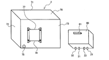
- FIG. 2 is a perspective view showing a refrigeration cycle device according to an embodiment of the present invention.
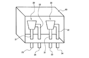
- FIG. 3 is a perspective view showing the inside of the storage box of the refrigeration cycle device according to the embodiment of the present invention.
- FIG. 3 is a diagram in which a part of the outer peripheral surface of the storage box 80 is transparent.
- the white arrow shown in FIG. 2 indicates the flow direction of the air blown out of the housing 70.
- An air outlet (not shown) is formed on the front surface portion 71 of the housing 70 of the outdoor unit 2.
- the outdoor air sucked into the housing 70 from the suction port (not shown) by the outdoor blower 13a exchanges heat with the refrigerant flowing through the outdoor heat exchanger 13.
- the outdoor air that has exchanged heat with the refrigerant flowing through the outdoor heat exchanger 13 is blown out of the housing 70 from the air outlet formed in the front surface portion 71, as shown by the white arrow in FIG. 2.
- a housing box 80 is provided on the back surface 73 of the housing 70. Specifically, the housing box 80 is arranged outside the housing 70 and attached to the back surface portion 73 of the housing 70.
- the housing 70 includes a mounting portion 74 on the back surface portion 73 to which the storage box 80 is mounted.
- the method of fixing the storage box 80 to the housing 70 is not particularly limited.
- the accommodation box 80 may be fixed to the housing 70 by screwing, or the accommodation box 80 may be fixed to the housing 70 by welding.
- the storage box 80 accommodates the first shutoff valve 20 and the second shutoff valve 30.
- the first cutoff valve 20 is connected to the third refrigerant pipe 43 and the fourth refrigerant pipe 44
- the second cutoff valve 30 is connected to the fifth refrigerant pipe 45 and the sixth refrigerant pipe 46.
- a first connecting portion 23 that is a connecting portion between the first cutoff valve 20 and the third refrigerant pipe 43
- a connecting portion that is a connecting portion between the first cutoff valve 20 and the fourth refrigerant pipe 44.
- connection part 24 which is a connection part of the 2nd cutoff valve 30 and the 5th refrigerant piping 45, and 4th connection part which is a connection part of the 2nd cutoff valve 30 and the 6th refrigerant piping 46.
- 34 is provided outside the housing box 80.
- the fifth refrigerant pipe 45 and the sixth refrigerant pipe 46 are connected to the second shutoff valve 30 when the refrigeration cycle apparatus 1 is installed.
- the connection work becomes easy.
- An opening 75 is formed in the back surface 73 of the housing 70.
- a knockout hole is formed in the back surface portion 73 of the housing 70.
- the knockout hole is a structure in which the opening is covered with a lid so that the opening can be easily opened at the site.
- the opening can be opened by pushing the lid of the knockout hole.
- the opening 75 is formed by pushing the lid of the knockout hole in the back surface portion 73 of the housing 70.
- the components of the refrigeration cycle circuit 10 housed in the housing 70 of the outdoor unit 2 and the second cutoff valve 30 are connected through the fifth refrigerant pipe 45 through the opening 75. Further, the control device 50 housed in the housing 70 of the outdoor unit 2 and the detection sensor 4 are connected by passing the wiring 61 through the opening 75. Further, the control device 50 housed in the housing 70 of the outdoor unit 2 and the first shutoff valve 20 are connected by passing the wiring 62 through the opening 75. Further, the control device 50 housed in the housing 70 of the outdoor unit 2 and the second cutoff valve 30 are connected by passing the wiring 63 through the opening 75.
- the accommodation box 80 can be easily fixed to the housing 70.
- FIG. 4 is a perspective view showing another example of the refrigeration cycle apparatus according to the embodiment of the present invention.
- the storage box 80 has a hook portion 81 on the surface facing the housing 70 of the outdoor unit 2.
- the hook portion 81 is, for example, a hook.
- the housing 70 of the outdoor unit 2 includes a hook portion 77 on which the hook portion 81 is hooked, on the mounting portion 74.
- a plate member is attached to the attachment portion 74. At this time, the plate member is attached so that a space into which the tip of the hooking portion 81 is inserted is formed between the plate member and the housing 70. By attaching the plate-like member in this manner, the upper edge portion of the plate-like member becomes the hook portion 77.
- the storage box 80 is temporarily fixed to the mounting position of the housing 70 by hooking the hook portion 81 of the storage box 80 on the hook portion 77 of the housing 70.
- the accommodation box 80 can be easily fixed to the housing 70. It is possible to shorten the time for fixing the storage box 80 to the 70.
- the worker performs the screwing work with the driver in one hand. At this time, since the worker does not need to hold the storage box 80 at the mounting position, the screwing work becomes easy and the screwing time can be shortened.
- the fixing position of the storage box 80 to the housing 70 described above is an example.
- the housing box 80 may be fixed to the housing 70 outside the housing 70.
- the storage box 80 may be fixed at the position shown in FIG. 5 below.
- FIG. 5 is a perspective view which shows another example of the refrigerating-cycle apparatus which concerns on embodiment of this invention.
- the storage box 80 is arranged outside the housing 70 and attached to the side surface portion 72 of the housing 70.
- the housing 70 includes the side surface 72 and the mounting portion 74 to which the storage box 80 is mounted.
- an opening 76 through which the third refrigerant pipe 43, the fifth refrigerant pipe 45, the wiring 61, the wiring 62 and the wiring 63 pass is formed in the side surface portion 72 of the housing 70.
- the side surface portion 72 of the housing 70 is formed with a knockout hole serving as the opening portion 76.
- the opening 76 is formed by pushing the lid of the knockout hole of the side surface 72 of the housing 70.
- the accommodation box 80 can be easily installed, and the first shutoff valve 20 and the second shutoff valve 30 can be easily installed.
- both the side surface portion 72 and the rear surface portion 73 of the housing 70 may be provided with mounting portions 74 to which the storage box 80 is mounted. With this configuration, it is possible to select which of the side surface portion 72 and the rear surface portion 73 the storage box 80 is fixed to, depending on the installation location of the outdoor unit 2, and the first shutoff valve 20. Also, the installation of the second cutoff valve 30 becomes easier.
- the refrigeration cycle apparatus 1 includes a refrigeration cycle circuit 10 configured by connecting a plurality of constituent devices with a refrigerant pipe, and a part of the plurality of constituent devices configuring the refrigeration cycle circuit 10.
- An outdoor unit 2 having a housing 70 in which is stored, and an indoor unit 3 in which a part of a plurality of constituent devices forming the refrigeration cycle circuit 10 is stored.
- the refrigeration cycle device 1 according to the present embodiment includes the detection sensor 4 that detects the refrigerant leaked from the refrigeration cycle circuit 10, the first cutoff valve 20 provided in the middle of the first refrigerant pipe 41, and the first cutoff valve 20.
- a second cutoff valve 30 provided in the middle of the two-refrigerant pipe 42 and a control device 50 are provided.
- the control device 50 closes the first cutoff valve 20 to cut off the flow of the refrigerant in the first refrigerant pipe 41 when the detected amount of the refrigerant detected by the detection sensor 4 becomes equal to or more than the specified amount, and then the second The shutoff valve 30 is closed to shut off the flow of the refrigerant in the second refrigerant pipe 42.
- the refrigeration cycle apparatus 1 according to the present embodiment houses the first shutoff valve 20 and the second shutoff valve 30, and is placed outside the housing 70 of the outdoor unit 2 and is attached to the housing 70. A box 80 is provided.
- a conventional refrigeration cycle device equipped with a shutoff valve for shutting off the circulation of the refrigerant in the refrigeration cycle circuit had a shutoff valve in the relay unit.
- the relay unit is installed, for example, in the space around the living space in the building, such as in the ceiling. Therefore, it may not be possible to secure the installation space for the relay unit in the building. Further, even if the installation space for the relay unit can be secured in the building, it is difficult to secure a large installation space for the relay unit, and the shutoff valve may not be provided in the relay unit.
- the conventional refrigeration cycle apparatus has a problem in that it is difficult to install the shutoff valve that shuts off the circulation of the refrigerant in the refrigeration cycle circuit.
- the housing box 80 is fixed to the housing 70 of the outdoor unit 2, and the housing box 80 houses the first shutoff valve 20 and the second shutoff valve 30. .. It is easy to secure a large installation space for the outdoor unit 2 as compared with the installation space for the relay unit. Therefore, in the refrigeration cycle device 1 according to the present embodiment, it is easier to install the first cutoff valve 20 and the second cutoff valve 30 that are cutoff valves that shut off the circulation of the refrigerant in the refrigeration cycle circuit. ..
- the refrigeration cycle apparatus 1 is provided with the housing box 80 outside the housing 70 of the outdoor unit 2, and houses the first shutoff valve 20 and the second shutoff valve 30 in the housing box 80. There is. Therefore, when the first shutoff valve 20 and the second shutoff valve 30 are provided in the conventional refrigeration cycle apparatus, it is necessary to secure an installation space for the first shutoff valve 20 and the second shutoff valve 30 inside the housing of the outdoor unit. There is no. Therefore, by providing the storage box 80, the first shutoff valve 20, and the second shutoff valve 30, the conventional refrigeration cycle apparatus can be easily made the refrigeration cycle apparatus 1 according to the present embodiment.
- the refrigeration cycle device 1 is configured to include only one indoor unit 3.
- the refrigeration cycle apparatus 1 may be configured to include a plurality of indoor units 3.
- the refrigeration cycle apparatus 1 may be configured to connect the outdoor unit 2 and the indoor unit 3 via a relay unit.
- the refrigeration cycle apparatus 1 can be various refrigeration cycle apparatuses including a refrigeration cycle circuit.
- the refrigeration cycle apparatus 1 may be used as a refrigeration apparatus in which the use side unit of the refrigeration cycle apparatus 1 is installed in a freezer and the use side unit cools the air in the freezer.
- the refrigeration cycle apparatus 1 may be used as a hot water supply apparatus by heating water with the use side heat exchanger of the use side unit.
- 1 refrigeration cycle device 2 outdoor unit, 3 indoor unit, 4 detection sensor, 10 refrigeration cycle circuit, 11 compressor, 12 four-way valve, 13 outdoor heat exchanger, 13a outdoor blower, 14 expansion valve, 15 indoor heat exchanger, 15a indoor blower, 20 first shutoff valve, 21 connecting pipe, 22 connecting pipe, 23 1st connecting part, 24 2nd connecting part, 30 2nd shutoff valve, 31 connecting pipe, 32 connecting pipe, 33rd connecting pipe 3 connection parts, 34 4th connection parts, 41 1st refrigerant pipes, 42 2nd refrigerant pipes, 43 3rd refrigerant pipes, 44 4th refrigerant pipes, 45 5th refrigerant pipes, 46 6th refrigerant pipes, 50 control device, 51 reception unit, 52 comparison unit, 53 control unit, 61 wiring, 62 wiring, 63 wiring, 70 casing, 71 front surface portion, 72 side surface portion, 73 rear surface portion, 74 mounting portion, 75 opening portion, 76 opening portion, 77 Hooking part, 80 storage box, 81 hooking part.
Landscapes
- Engineering & Computer Science (AREA)
- Mechanical Engineering (AREA)
- General Engineering & Computer Science (AREA)
- Physics & Mathematics (AREA)
- Thermal Sciences (AREA)
- Chemical & Material Sciences (AREA)
- Combustion & Propulsion (AREA)
- Other Air-Conditioning Systems (AREA)
Abstract
本発明に係る冷凍サイクル装置は、冷凍サイクル回路の構成機器が収容された室外ユニット及び利用側ユニットを備えている。また、本発明に係る冷凍サイクル装置は、前記室外ユニットと前記利用側ユニットとが第1冷媒配管及び第2冷媒配管で接続されており、前記第1冷媒配管に設けられた第1遮断弁と、前記第2冷媒配管に設けられた第2遮断弁と、前記第1遮断弁及び前記第2遮断弁を収容し、前記室外ユニットの前記筐体の外部に配置されて該筐体に取り付けられる収容箱と、を備えている。
Description
本発明は、冷媒の漏洩の抑制を図った冷凍サイクル装置に関する。
冷凍サイクル装置は、使用する冷媒等によっては、冷凍サイクル装置の外部へ冷媒が漏洩することを抑制する必要がある。例えば、近年、欧州では、Fガスの放出を規制する動きが強化されている。欧州では、HFC(ハイドロフルオロカーボン)、PFC(パーフルオロカーボン)、及びSF6(六フッ化硫黄)をFガスと呼んでいる。このため、近年、冷凍サイクル装置の一例である空気調和装置においては、HFC冷媒の一種である不燃性冷媒のR410A冷媒に換えて、温暖化係数がR410Aよりも小さいR32冷媒等の可燃性冷媒を用いる場合がある。
上述のような可燃性冷媒を用いる場合、安全性等の観点から、居住空間へ冷媒が漏洩することを抑制する必要がある。このため、従来の空気調和装置には、居住空間への冷媒の漏洩を検出する検出センサと、冷凍サイクル回路内の冷媒の循環を遮断する遮断弁とを備えたものも提案されている(特許文献1参照)。具体的には、従来の空気調和装置は、室外ユニットと、利用側ユニットである複数の室内ユニットと、室外ユニットと室内ユニットとを接続する複数の中継ユニットと、を備えている。また、従来の空気調和装置は、室内ユニットに、冷媒の漏洩を検出する検出センサを備えている。また、従来の空気調和装置は、中継ユニットに、冷凍サイクル回路内の冷媒の循環を遮断する遮断弁を備えている。そして、従来の空気調和装置は、検出センサによって居住空間への冷媒の漏洩が検出された際、中継ユニットの遮断弁によって冷凍サイクル回路内の冷媒の循環を遮断し、居住空間へ冷媒が漏洩することを抑制している。
中継ユニットは、例えば天井裏等、建物内における居住空間周辺の空間に設置される。このため、建物内に中継ユニットの設置スペースを確保できない場合がある。また、建物内に中継ユニットの設置スペースを確保できる場合でも、中継ユニットの設置スペースを大きく確保することが難しく、遮断弁を中継ユニットに設けられない場合がある。このように、従来の冷凍サイクル装置は、冷凍サイクル回路内の冷媒の循環を遮断する遮断弁を設置することが難しいという課題があった。
本発明は、上述の課題を解決するためになされたものであり、冷凍サイクル回路内の冷媒の循環を遮断する遮断弁の設置が従来よりも容易となる冷凍サイクル装置を得ることを目的とする。
本発明に係る冷凍サイクル装置は、複数の構成機器を有し、複数の前記構成機器が冷媒配管で接続されて構成される冷凍サイクル回路と、複数の前記構成機器のうちの一部が収容された筐体を有する室外ユニットと、複数の前記構成機器のうちの一部が収容された利用側ユニットと、を備えた冷凍サイクル装置であって、前記室外ユニットの前記筐体に収容された前記構成機器と前記利用側ユニットに収容された前記構成機器とを接続する前記冷媒配管のうち、ガス状冷媒又は超臨界状態の冷媒が流れる前記冷媒配管を第1冷媒配管とし、前記室外ユニットの前記筐体に収容された前記構成機器と前記利用側ユニットに収容された前記構成機器とを接続する前記冷媒配管のうち、液状冷媒又は気液二相状態の冷媒が流れる前記冷媒配管を第2冷媒配管とした場合、前記冷凍サイクル回路から漏洩した冷媒を検出する検出センサと、前記第1冷媒配管の途中部に設けられた第1遮断弁と、前記第2冷媒配管の途中部に設けられた第2遮断弁と、前記検出センサで検出された冷媒の検出量が規定量以上となった際に、前記第1遮断弁を閉じて前記第1冷媒配管内の冷媒の流通を遮断し、前記第2遮断弁を閉じて前記第2冷媒配管内の冷媒の流通を遮断する制御装置と、前記第1遮断弁及び前記第2遮断弁を収容し、前記室外ユニットの前記筐体の外部に配置されて該筐体に取り付けられる収容箱と、を備えている。
室外ユニットの設置スペースは、中継ユニットの設置スペースと比べて、大きく確保しやすい。このため、本発明に係る冷凍サイクル装置は、冷凍サイクル回路内の冷媒の循環を遮断する遮断弁である第1遮断弁及び第2遮断弁の設置が従来よりも容易となる。
以下の実施の形態において、本発明に係る冷凍サイクル装置の一例を説明する。なお、以下の実施の形態では、本発明に係る冷凍サイクル装置を空気調和装置として用いた例を説明する。
実施の形態.
図1は、本発明の実施の形態に係る冷凍サイクル装置を示す冷媒回路図である。
本実施の形態に係る冷凍サイクル装置1は、冷媒が循環する冷凍サイクル回路10を備えている。冷凍サイクル回路10は、複数の構成機器を有し、これらの複数の構成機器が冷媒配管で接続されて構成されている。本実施の形態においては、冷凍サイクル回路10は、該冷凍サイクル回路10の構成機器として、圧縮機11、四方弁12、室外熱交換器13、膨張弁14、及び、利用側熱交換器の一例である室内熱交換器15を備えている。
図1は、本発明の実施の形態に係る冷凍サイクル装置を示す冷媒回路図である。
本実施の形態に係る冷凍サイクル装置1は、冷媒が循環する冷凍サイクル回路10を備えている。冷凍サイクル回路10は、複数の構成機器を有し、これらの複数の構成機器が冷媒配管で接続されて構成されている。本実施の形態においては、冷凍サイクル回路10は、該冷凍サイクル回路10の構成機器として、圧縮機11、四方弁12、室外熱交換器13、膨張弁14、及び、利用側熱交換器の一例である室内熱交換器15を備えている。
圧縮機11は、吸入した低圧のガス状冷媒を圧縮し、高圧のガス状冷媒として吐出する。なお、冷凍サイクル回路10内を循環する冷媒によっては、二酸化炭素冷媒等のように、超臨界状態の冷媒として圧縮機11から吐出される冷媒もある。四方弁12は、冷房運転時と暖房運転時とによって冷媒の流れを切り換える弁である。なお、後述のように、本実施の形態では、利用側熱交換器である室内熱交換器15は、暖房運転時においては放熱器として機能し、冷房運転時においては蒸発器として機能する。このため、冷凍サイクル回路10は、四方弁12を備えている。しかしながら、利用側熱交換器が放熱器又は蒸発器の一方としてのみ機能すればよい場合、冷凍サイクル回路10は、四方弁12を備えていなくてもよい。
室外熱交換器13は、冷媒と室外空気との熱交換を行う。室外熱交換器13は、暖房運転時においては蒸発器として機能し、冷媒を蒸発させて気化させる。また、室外熱交換器13は、冷房運転時においては放熱器として機能し、冷媒から放熱させて該冷媒を液化させる。なお、本実施の形態では、室外熱交換器13を流れる冷媒と室外空気との熱交換を促進させるため、室外熱交換器13の周辺に、該室外熱交換器13へ室外空気を供給する室外送風機13aを設けている。
膨張弁14は、例えば絞り装置等であり、冷媒を減圧して膨張させる。室内熱交換器15は、空調対象空間である室内の空気と冷媒との熱交換を行う。室内熱交換器15は、暖房運転時においては放熱器として機能し、冷媒から放熱させて該冷媒を液化させる。また、室内熱交換器15は、冷房運転時においては蒸発器として機能し、冷媒を蒸発させて気化させる。なお、本実施の形態では、室内熱交換器15を流れる冷媒と室内空気との熱交換を促進させるため、室内熱交換器15の周辺に、該室内熱交換器15へ室内空気を供給する室内送風機15aを設けている。
冷凍サイクル回路10の構成機器は、室外ユニット2又は利用側ユニットの一例である室内ユニット3に収容されている。なお、室外ユニット2と室内ユニット3とが中継ユニットを介して接続される場合、冷凍サイクル回路10の構成機器の一部を中継ユニットに収容してもよい。すなわち、冷凍サイクル回路10の構成機器の一部は、室外ユニット2に収容されている。また、冷凍サイクル回路10の構成機器の一部は、室内ユニット3に収容されている。
詳しくは、本実施の形態の場合、室外ユニット2は、筐体70を備えている。そして、筐体70には、圧縮機11、四方弁12、室外熱交換器13、及び膨張弁14が収容されている。また、室内ユニット3には、室内熱交換器15が収容されている。なお、室外ユニット2の筐体70及び室内ユニット3に収容される冷凍サイクル回路10の構成機器の種類は、あくまでも一例である。例えば、膨張弁14を室内ユニット3に収容してもよい。
また、本実施の形態に係る冷凍サイクル装置1は、空調対象空間である室内に冷媒が漏洩することを抑制するため、冷媒の漏洩を検出する検出センサ4、第1遮断弁20、第2遮断弁30、及び制御装置50を備えている。
検出センサ4は、冷凍サイクル回路10から漏洩した冷媒を検出するセンサである。本実施の形態では、検出センサ4は、室内ユニット3に収容されており、室内ユニット3に取り込まれた室内空気に含まれる冷媒の量を検出する。なお、室内空気に含まれる冷媒の量を検出できれば、検出センサ4の設置箇所は室内ユニット3に限定されない。例えば、室内ユニット3の外部であって室内となる箇所に、検出センサ4を設けてもよい。また、検出センサ4の種類も特には限定されるものではなく、使用する冷媒に応じて、空気中の冷媒検出に用いられる公知の種々のセンサを検出センサ4として採用できる。
第1遮断弁20及び第2遮断弁30は、冷凍サイクル回路10内の冷媒の循環を遮断するものである。室外ユニット2の筐体70に収容された冷凍サイクル回路10の構成機器と、室内ユニット3に収容された冷凍サイクル回路10の構成機器とは、第1冷媒配管41及び第2冷媒配管42で接続されている。第1冷媒配管41は、ガス状冷媒又は超臨界状態の冷媒が流れる冷媒配管である。本実施の形態の場合、四方弁12と室内熱交換器15とを接続する接続配管が、第1冷媒配管41となる。第2冷媒配管42は、液状冷媒又は気液二相状態の冷媒が流れる冷媒配管である。本実施の形態の場合、膨張弁14と室内熱交換器15とを接続する配管が、第2冷媒配管42となる。第1遮断弁20は、第1冷媒配管41の途中部に設けられている。また、第2遮断弁30は、第2冷媒配管42の途中部に設けられている。
すなわち、第1遮断弁20を閉じることにより、第1冷媒配管41内の冷媒の流通を遮断することができる。また、第2遮断弁30を閉じることにより、第2冷媒配管42内の冷媒の流通を遮断することができる。ここで、第2遮断弁30には、第2冷媒配管42を流れる液状冷媒又は気液二相状態の冷媒が通過する。また、第1遮断弁20には、第1冷媒配管41を流れるガス状冷媒又は超臨界状態の冷媒が通過する。このため、第2遮断弁30を通過する冷媒の質量流量と第1遮断弁20を通過する冷媒の質量流量とを同程度にしようとした場合、第2遮断弁30に形成された冷媒が通る流路の断面積を、第1遮断弁20に形成された冷媒が通る流路の断面積よりも小さくすることができる。このため、本実施の形態においては、第2遮断弁30に形成された冷媒が通る流路の断面積は、第1遮断弁20に形成された冷媒が通る流路の断面積よりも小さくなっている。これにより、第2遮断弁30が第1遮断弁20と比べて安価になる。したがって、冷凍サイクル装置1の製造コストを低減することができる。
また、液状冷媒又は気液二相状態の冷媒の流れを遮断する機構に求められる密閉度は、ガス状冷媒又は超臨界状態の冷媒の流れを遮断する機構に求められる密閉度よりも低い。このため、本実施の形態においては、第2遮断弁30が閉じられた際の該第2遮断弁30の密閉度は、第1遮断弁20が閉じられた際の該第1遮断弁20の密閉度よりも低くなっている。これにより、第2遮断弁30が第1遮断弁20と比べて安価になる。したがって、冷凍サイクル装置1の製造コストを低減することができる。
なお、以下では、第1冷媒配管41のうち、室外ユニット2の筐体70に収容された冷凍サイクル回路10の構成機器と第1遮断弁20とを接続する部分を、第3冷媒配管43とする。第1冷媒配管41のうち、室内ユニット3に収容された冷凍サイクル回路10の構成機器と第1遮断弁20とを接続する部分を、第4冷媒配管44とする。第2冷媒配管42のうち、室外ユニット2の筐体70に収容された冷凍サイクル回路10の構成機器と第2遮断弁30とを接続する部分を、第5冷媒配管45とする。第2冷媒配管42のうち、室内ユニット3に収容された冷凍サイクル回路10の構成機器と第2遮断弁30とを接続する部分を、第6冷媒配管46とする。
また、以下では、第1遮断弁20と第3冷媒配管43との接続部を、第1接続部23とする。なお、本実施の形態では、第1遮断弁20は接続用配管21を有し、該接続用配管21の端部に第3冷媒配管43が接続されている。このため、本実施の形態では、接続用配管21の端部が第1接続部23となっている。また、第1遮断弁20と第4冷媒配管44との接続部を、第2接続部24とする。なお、本実施の形態では、第1遮断弁20は接続用配管22を有し、該接続用配管22の端部に第4冷媒配管44が接続されている。このため、本実施の形態では、接続用配管22の端部が第2接続部24となっている。また、第2遮断弁30と第5冷媒配管45との接続部を、第3接続部33とする。なお、本実施の形態では、第2遮断弁30は接続用配管31を有し、該接続用配管31の端部に第5冷媒配管45が接続されている。このため、本実施の形態では、接続用配管31の端部が第3接続部33となっている。また、第2遮断弁30と第6冷媒配管46との接続部を第4接続部34とする。なお、本実施の形態では、第2遮断弁30は接続用配管32を有し、該接続用配管32の端部に第6冷媒配管46が接続されている。このため、本実施の形態では、接続用配管32の端部が第4接続部34となっている。
制御装置50は、圧縮機11の駆動時の回転数、四方弁12の流路、膨張弁14の開度、室外送風機13aの回転数、室内送風機15aの回転数、第1遮断弁20の開閉、及び第2遮断弁30の開閉等の制御を行う。この制御装置50は、専用のハードウェア、又はメモリに格納されるプログラムを実行するCPU(Central Processing Unit)で構成されている。なお、CPUは、中央処理装置、処理装置、演算装置、マイクロプロセッサ、マイクロコンピュータ、又はプロセッサともいう。
制御装置50が専用のハードウェアである場合、制御装置50は、例えば、単一回路、複合回路、ASIC(Application Specific Integrated Circuit)、FPGA(Field-Programmable Gate Array)、又はこれらを組み合わせたものが該当する。制御装置50が実現する各機能部のそれぞれを、個別のハードウェアで実現してもよいし、各機能部を一つのハードウェアで実現してもよい。
制御装置50がCPUの場合、制御装置50が実行する各機能は、ソフトウェア、ファームウェア、又はソフトウェアとファームウェアとの組み合わせにより実現される。ソフトウェア及びファームウェアはプログラムとして記述され、メモリに格納される。CPUは、メモリに格納されたプログラムを読み出して実行することにより、制御装置50の各機能を実現する。ここで、メモリは、例えば、RAM、ROM、フラッシュメモリ、EPROM、又はEEPROM等の、不揮発性又は揮発性の半導体メモリである。
制御装置50の機能の一部を専用のハードウェアで実現し、一部をソフトウェア又はファームウェアで実現するようにしてもよい。また、本実施の形態では制御装置50を1つの制御装置として構成して室外ユニット2に収容しているが、制御装置50を複数の制御装置に分けて構成してもよい。そして、室内ユニット3に収容されている構成機器を制御する制御装置を、室内ユニット3に収容してもよい。
本実施の形態に係る制御装置50は、第1遮断弁20及び第2遮断弁30を制御する機能部として、受信部51、比較部52、及び制御部53を備えている。受信部51は、検出センサ4の検出結果を受信する機能部である。換言すると、受信部51は、冷凍サイクル回路10から空調対象空間である室内の空気にどの程度の冷媒が漏洩したかを受信する。なお、本実施の形態では、制御装置50と検出センサ4とは配線61で接続されている。そして、受信部51は、配線61を介して、検出センサ4の検出結果を受信する。すなわち、配線61は、通信線を備えている。なお、配線61は、検出センサ4へ電力を供給する電力供給線を備えていてもよい。
比較部52は、検出センサ4で検出された冷媒の検出量と閾値である規定量とを比較する機能部である。換言すると、比較部52は、検出センサ4の検出値と閾値である規定量とを比較する機能部である。制御部53は、検出センサ4で検出された冷媒の検出量が規定量以上となった際に、第1遮断弁20及び第2遮断弁30を閉じる機能部である。第1遮断弁20を閉じることにより、第1冷媒配管41内の冷媒の流通を遮断することができる。また、第2遮断弁30を閉じることにより、第2冷媒配管42内の冷媒の流通を遮断することができる。すなわち、第1遮断弁20及び第2遮断弁30を閉じることにより、冷凍サイクル回路10内の冷媒の循環を遮断することができる。
本実施の形態では、制御装置50と第1遮断弁20とは配線62で接続されている。そして、制御部53は、配線62を介して、第1遮断弁20へ開閉の指令を行う。すなわち、配線62は、通信線を備えている。なお、配線62は、第1遮断弁20へ電力を供給する電力供給線を備えていてもよい。また、本実施の形態では、制御装置50と第2遮断弁30とは配線63で接続されている。そして、制御部53は、配線63を介して、第2遮断弁30へ開閉の指令を行う。すなわち、配線63は、通信線を備えている。なお、配線63は、第2遮断弁30へ電力を供給する電力供給線を備えていてもよい。
ここで、冷凍サイクル回路内の冷媒の循環を遮断する遮断弁を備えた従来の冷凍サイクル装置は、上述のように、遮断弁を中継ユニットに設けていた。このため、冷凍サイクル回路内の冷媒の循環を遮断する遮断弁を備えた従来の冷凍サイクル装置は、遮断弁を制御する制御基板等の制御装置も、中継ユニットに設ける必要があった。したがって、冷凍サイクル回路内の冷媒の循環を遮断する遮断弁を備えた従来の冷凍サイクル装置は、遮断弁を制御する制御基板等の制御装置を新たに設ける必要があり、冷凍サイクル装置の製造コストが増加するという課題があった。
一方、後述のように、本実施の形態に係る冷凍サイクル装置1においては、第1遮断弁20及び第2遮断弁30は、室外ユニット2の近傍に設けられる。このため、本実施の形態に係る冷凍サイクル装置1においては、第1遮断弁20及び第2遮断弁30は、室外ユニット2に設けられた制御装置50によって制御される。通常、室外ユニットには、制御装置が設けられている。このため、本実施の形態に係る冷凍サイクル装置1においては、第1遮断弁20及び第2遮断弁30を制御するための制御装置を新たに設ける必要がない。したがって、本実施の形態に係る冷凍サイクル装置1は、冷凍サイクル回路内の冷媒の循環を遮断する遮断弁を備えた従来の冷凍サイクル装置と比べ、製造コストを低減することができる。
図2は、本発明の実施の形態に係る冷凍サイクル装置を示す斜視図である。また、図3は、本発明の実施の形態に係る冷凍サイクル装置の収容箱の内部を示す斜視図である。換言すると、図3は、収容箱80の外周面の一部を透過した図となっている。なお、図2に示す白抜き矢印は、筐体70の外部へ吹き出される空気の流れ方向を示している。以下、図2及び図3を用いて、第1遮断弁20及び第2遮断弁30の設置構成の詳細を説明する。
室外ユニット2の筐体70の前面部71には、図示せぬ吹出口が形成されている。室外送風機13aによって図示せぬ吸込口から筐体70内に吸い込まれた室外空気は、室外熱交換器13を流れる冷媒と熱交換する。室外熱交換器13を流れる冷媒と熱交換した室外空気は、図2に白抜き矢印で示すように、前面部71に形成されている吹出口から筐体70の外部に吹き出される。また、筐体70の背面部73には、収容箱80が設けられている。詳しくは、収容箱80は、筐体70の外部に配置されて、該筐体70の背面部73に取り付けられている。換言すると、筐体70は、背面部73に、収容箱80が取り付けられる取付部74を備えている。なお、筐体70への収容箱80の固定方法は、特に限定されない。例えば、ネジ止めによって筐体70へ収容箱80を固定してもよいし、溶接によって筐体70へ収容箱80を固定してもよい。
図3に示すように、収容箱80には、第1遮断弁20及び第2遮断弁30が収容されている。上述のように、第1遮断弁20は第3冷媒配管43及び第4冷媒配管44と接続され、第2遮断弁30は第5冷媒配管45及び第6冷媒配管46と接続される。ここで、本実施の形態では、第1遮断弁20と第3冷媒配管43との接続部である第1接続部23、第1遮断弁20と第4冷媒配管44との接続部である第2接続部24、第2遮断弁30と第5冷媒配管45との接続部である第3接続部33、及び第2遮断弁30と第6冷媒配管46との接続部である第4接続部34が、収容箱80の外部に設けられている。第1接続部23及び第2接続部24を収容箱80の外部に配置することにより、冷凍サイクル装置1の据付時に第1遮断弁20へ第3冷媒配管43及び第4冷媒配管44を接続する際、当該接続作業が容易となる。また、第3接続部33及び第4接続部34を収容箱80の外部に配置することにより、冷凍サイクル装置1の据付時に第2遮断弁30へ第5冷媒配管45及び第6冷媒配管46を接続する際、当該接続作業が容易となる。
なお、筐体70の背面部73には、開口部75が形成されている。具体的には、筐体70の背面部73には、ノックアウト穴が形成されている。ノックアウト穴とは、現場において簡単に開口部が開けられるように、該開口部が蓋で塞がれた構造である。ノックアウト穴の蓋を押すことにより、開口部を開けられるようになっている。本実施の形態では、筐体70の背面部73のノックアウト穴の蓋を押すことにより、開口部75が形成される。そして、室外ユニット2の筐体70に収容された冷凍サイクル回路10の構成機器と第1遮断弁20とは、第3冷媒配管43を開口部75に通して接続されている。また、室外ユニット2の筐体70に収容された冷凍サイクル回路10の構成機器と第2遮断弁30とは、第5冷媒配管45を開口部75に通して接続されている。また、室外ユニット2の筐体70に収容された制御装置50と検出センサ4とは、配線61を開口部75に通して接続されている。また、室外ユニット2の筐体70に収容された制御装置50と第1遮断弁20とは、配線62を開口部75に通して接続されている。また、室外ユニット2の筐体70に収容された制御装置50と第2遮断弁30とは、配線63を開口部75に通して接続されている。
ここで、以下の図4に示すような仮固定構造を冷凍サイクル装置1に採用することにより、筐体70への収容箱80の固定が容易となる。
図4は、本発明の実施の形態に係る冷凍サイクル装置の別の一例を示す斜視図である。
図4に示す冷凍サイクル装置1においては、収容箱80は、室外ユニット2の筐体70と対向する面に、引掛け部81を備えている。引掛け部81は、例えば、フックである。また、室外ユニット2の筐体70は、取付部74に、引掛け部81が引っ掛けられる引っ掛かり部77を備えている。本実施の形態では、取付部74に板状部材を取り付けている。この際、板状部材は、筐体70との間に引掛け部81の先端部が挿入される空間が形成されるように、取り付けられている。このように板状部材を取り付けることにより、板状部材の上縁部が引っ掛かり部77となる。
図4に示す冷凍サイクル装置1においては、収容箱80は、室外ユニット2の筐体70と対向する面に、引掛け部81を備えている。引掛け部81は、例えば、フックである。また、室外ユニット2の筐体70は、取付部74に、引掛け部81が引っ掛けられる引っ掛かり部77を備えている。本実施の形態では、取付部74に板状部材を取り付けている。この際、板状部材は、筐体70との間に引掛け部81の先端部が挿入される空間が形成されるように、取り付けられている。このように板状部材を取り付けることにより、板状部材の上縁部が引っ掛かり部77となる。
収容箱80の引掛け部81を筐体70の引っ掛かり部77に引っ掛けることにより、収容箱80は、筐体70の取り付け位置に仮固定されることとなる。このように、収容箱80を筐体70の取り付け位置に仮固定した状態で、筐体70へ収容箱80を固定することにより、筐体70への収容箱80の固定が容易となり、筐体70への収容箱80の固定作業の時間を短縮することができる。例えば、ネジ止めによって筐体70へ収容箱80を固定する場合、作業者は、片手にドライバーを持った状態でネジ止め作業を行うことになる。この際、作業者は、収容箱80を取り付け位置に保持する必要がないので、ネジ止め作業が容易となり、ネジ止め作業の時間を短縮することができる。
また、上述した筐体70への収容箱80の固定位置は、一例である。収容箱80は、筐体70の外部において、筐体70に固定されていればよい。例えば、以下の図5に示す位置に、収容箱80が固定されていてもよい。
図5は、本発明の実施の形態に係る冷凍サイクル装置の別の一例を示す斜視図である。
図5に示す冷凍サイクル装置1においては、収容箱80は、筐体70の外部に配置されて、該筐体70の側面部72に取り付けられている。換言すると、筐体70は、側面部72に、収容箱80が取り付けられる取付部74を備えている。また、図5に示す冷凍サイクル装置1においては、筐体70の側面部72に、第3冷媒配管43、第5冷媒配管45、配線61、配線62及び配線63が通る開口部76が形成されている。具体的には、筐体70の側面部72には、開口部76となるノックアウト穴が形成されている。筐体70の側面部72のノックアウト穴の蓋を押すことにより、開口部76が形成される。
図5に示す冷凍サイクル装置1においては、収容箱80は、筐体70の外部に配置されて、該筐体70の側面部72に取り付けられている。換言すると、筐体70は、側面部72に、収容箱80が取り付けられる取付部74を備えている。また、図5に示す冷凍サイクル装置1においては、筐体70の側面部72に、第3冷媒配管43、第5冷媒配管45、配線61、配線62及び配線63が通る開口部76が形成されている。具体的には、筐体70の側面部72には、開口部76となるノックアウト穴が形成されている。筐体70の側面部72のノックアウト穴の蓋を押すことにより、開口部76が形成される。
室外ユニット2の設置場所によっては、筐体70の背面側に、収容箱80の設置スペースの確保が難しい場合もある。この様な設置環境においては、図5のように冷凍サイクル装置1を構成することにより、収容箱80の設置が容易となり、第1遮断弁20及び第2遮断弁30の設置が容易となる。
なお、筐体70の側面部72及び背面部73の双方に、収容箱80が取り付けられる取付部74を備えていてもよい。このように構成することにより、室外ユニット2の設置場所に応じて、側面部72及び背面部73のうちのどちら側に収容箱80を固定するかを選択することができ、第1遮断弁20及び第2遮断弁30の設置がさらに容易となる。
以上、本実施の形態に係る冷凍サイクル装置1は、複数の構成機器が冷媒配管で接続されて構成される冷凍サイクル回路10と、冷凍サイクル回路10を構成する複数の構成機器のうちの一部が収容された筐体70を有する室外ユニット2と、冷凍サイクル回路10を構成する複数の構成機器のうちの一部が収容された室内ユニット3と、を備えている。また、本実施の形態に係る冷凍サイクル装置1は、冷凍サイクル回路10から漏洩した冷媒を検出する検出センサ4と、第1冷媒配管41の途中部に設けられた第1遮断弁20と、第2冷媒配管42の途中部に設けられた第2遮断弁30と、制御装置50と、を備えている。制御装置50は、検出センサ4で検出された冷媒の検出量が規定量以上となった際に、第1遮断弁20を閉じて第1冷媒配管41内の冷媒の流通を遮断し、第2遮断弁30を閉じて第2冷媒配管42内の冷媒の流通を遮断する。そして、本実施の形態に係る冷凍サイクル装置1は、第1遮断弁20及び第2遮断弁30を収容し、室外ユニット2の筐体70の外部に配置されて該筐体70に取り付けられる収容箱80を備えている。
冷凍サイクル回路内の冷媒の循環を遮断する遮断弁を備えた従来の冷凍サイクル装置は、中継ユニットに遮断弁を備えていた。中継ユニットは、例えば天井裏等、建物内における居住空間周辺の空間に設置される。このため、建物内に中継ユニットの設置スペースを確保できない場合がある。また、建物内に中継ユニットの設置スペースを確保できる場合でも、中継ユニットの設置スペースを大きく確保することが難しく、遮断弁を中継ユニットに設けられない場合がある。このように、従来の冷凍サイクル装置は、冷凍サイクル回路内の冷媒の循環を遮断する遮断弁を設置することが難しいという課題があった。一方、本実施の形態に係る冷凍サイクル装置1は、室外ユニット2の筐体70に収容箱80を固定し、該収容箱80に第1遮断弁20及び第2遮断弁30を収容している。室外ユニット2の設置スペースは、中継ユニットの設置スペースと比べて、大きく確保しやすい。このため、本実施の形態に係る冷凍サイクル装置1は、冷凍サイクル回路内の冷媒の循環を遮断する遮断弁である第1遮断弁20及び第2遮断弁30の設置が従来よりも容易となる。
また、本実施の形態に係る冷凍サイクル装置1は、室外ユニット2の筐体70の外部に収容箱80を設け、該収容箱80に第1遮断弁20及び第2遮断弁30を収容している。このため、従来の冷凍サイクル装置に第1遮断弁20及び第2遮断弁30を設ける際、室外ユニットの筐体の内部に第1遮断弁20及び第2遮断弁30の設置スペースを確保する必要がない。このため、収容箱80、第1遮断弁20及び第2遮断弁30を設けることにより、従来の冷凍サイクル装置を容易に本実施の形態に係る冷凍サイクル装置1とすることができる。
なお、本実施の形態では、冷凍サイクル装置1は、室内ユニット3を1つのみ備えた構成となっていた。これに限らず、冷凍サイクル装置1は、複数の室内ユニット3を備える構成となっていてもよい。また例えば、冷凍サイクル装置1は、中継ユニットを介して、室外ユニット2と室内ユニット3とが接続される構成となっていてもよい。
また、本実施の形態では、冷凍サイクル装置1が空気調和装置として用いられる例について説明した。換言すると、本実施の形態では、冷凍サイクル装置1の利用側ユニットが室内ユニット3として用いられる例について説明した。これに限らず、冷凍サイクル装置1は、冷凍サイクル回路を備えた種々の冷凍サイクル装置とすることができる。例えば、冷凍サイクル装置1の利用側ユニットを冷凍庫に設置し、利用側ユニットで冷凍庫内の空気を冷却する冷凍装置として、冷凍サイクル装置1を用いてもよい。また例えば、利用側ユニットの利用側熱交換器で水を加熱し、給湯装置として冷凍サイクル装置1を用いてもよい。
1 冷凍サイクル装置、2 室外ユニット、3 室内ユニット、4 検出センサ、10 冷凍サイクル回路、11 圧縮機、12 四方弁、13 室外熱交換器、13a 室外送風機、14 膨張弁、15 室内熱交換器、15a 室内送風機、20 第1遮断弁、21 接続用配管、22 接続用配管、23 第1接続部、24 第2接続部、30 第2遮断弁、31 接続用配管、32 接続用配管、33 第3接続部、34 第4接続部、41 第1冷媒配管、42 第2冷媒配管、43 第3冷媒配管、44 第4冷媒配管、45 第5冷媒配管、46 第6冷媒配管、50 制御装置、51 受信部、52 比較部、53 制御部、61 配線、62 配線、63 配線、70 筐体、71 前面部、72 側面部、73 背面部、74 取付部、75 開口部、76 開口部、77 引っ掛かり部、80 収容箱、81 引掛け部。
Claims (8)
- 複数の構成機器を有し、複数の前記構成機器が冷媒配管で接続されて構成される冷凍サイクル回路と、
複数の前記構成機器のうちの一部が収容された筐体を有する室外ユニットと、
複数の前記構成機器のうちの一部が収容された利用側ユニットと、
を備えた冷凍サイクル装置であって、
前記室外ユニットの前記筐体に収容された前記構成機器と前記利用側ユニットに収容された前記構成機器とを接続する前記冷媒配管のうち、ガス状冷媒又は超臨界状態の冷媒が流れる前記冷媒配管を第1冷媒配管とし、
前記室外ユニットの前記筐体に収容された前記構成機器と前記利用側ユニットに収容された前記構成機器とを接続する前記冷媒配管のうち、液状冷媒又は気液二相状態の冷媒が流れる前記冷媒配管を第2冷媒配管とした場合、
前記冷凍サイクル回路から漏洩した冷媒を検出する検出センサと、
前記第1冷媒配管の途中部に設けられた第1遮断弁と、
前記第2冷媒配管の途中部に設けられた第2遮断弁と、
前記検出センサで検出された冷媒の検出量が規定量以上となった際に、前記第1遮断弁を閉じて前記第1冷媒配管内の冷媒の流通を遮断し、前記第2遮断弁を閉じて前記第2冷媒配管内の冷媒の流通を遮断する制御装置と、
前記第1遮断弁及び前記第2遮断弁を収容し、前記室外ユニットの前記筐体の外部に配置されて該筐体に取り付けられる収容箱と、
を備えた冷凍サイクル装置。 - 前記制御装置は、前記室外ユニットに収容されている請求項1に記載の冷凍サイクル装置。
- 前記第1冷媒配管のうち、前記室外ユニットの前記筐体に収容された前記構成機器と前記第1遮断弁とを接続する部分を第3冷媒配管とし、
前記第1冷媒配管のうち、前記利用側ユニットに収容された前記構成機器と前記第1遮断弁とを接続する部分を第4冷媒配管とし、
前記第2冷媒配管のうち、前記室外ユニットの前記筐体に収容された前記構成機器と前記第2遮断弁とを接続する部分を第5冷媒配管とし、
前記第2冷媒配管のうち、前記利用側ユニットに収容された前記構成機器と前記第2遮断弁とを接続する部分を第6冷媒配管とした場合、
前記第1遮断弁と前記第3冷媒配管との接続部である第1接続部、前記第1遮断弁と前記第4冷媒配管との接続部である第2接続部、前記第2遮断弁と前記第5冷媒配管との接続部である第3接続部、及び前記第2遮断弁と前記第6冷媒配管との接続部である第4接続部は、前記収容箱の外部に設けられている請求項1又は請求項2に記載の冷凍サイクル装置。 - 前記筐体は、側面部及び背面部の双方に、前記収容箱が取り付けられる取付部を備えている請求項1~請求項3のいずれか一項に記載の冷凍サイクル装置。
- 前記筐体は、側面部又は背面部に、前記収容箱が取り付けられる取付部を備えている請求項1~請求項3のいずれか一項に記載の冷凍サイクル装置。
- 前記収容箱は引掛け部を備え、
前記筐体は、前記取付部に、前記引掛け部が引っ掛けられる引っ掛かり部を備えている請求項4又は請求項5に記載の冷凍サイクル装置。 - 前記第2遮断弁に形成された冷媒が通る流路の断面積は、前記第1遮断弁に形成された冷媒が通る流路の断面積よりも小さい請求項1~請求項6のいずれか一項に記載の冷凍サイクル装置。
- 前記第2遮断弁が閉じられた際の該第2遮断弁の密閉度は、前記第1遮断弁が閉じられた際の該第1遮断弁の密閉度よりも低い請求項1~請求項7のいずれか一項に記載の冷凍サイクル装置。
Priority Applications (2)
| Application Number | Priority Date | Filing Date | Title |
|---|---|---|---|
| JP2020557104A JP6972380B2 (ja) | 2018-11-22 | 2018-11-22 | 冷凍サイクル装置 |
| PCT/JP2018/043231 WO2020105177A1 (ja) | 2018-11-22 | 2018-11-22 | 冷凍サイクル装置 |
Applications Claiming Priority (1)
| Application Number | Priority Date | Filing Date | Title |
|---|---|---|---|
| PCT/JP2018/043231 WO2020105177A1 (ja) | 2018-11-22 | 2018-11-22 | 冷凍サイクル装置 |
Publications (1)
| Publication Number | Publication Date |
|---|---|
| WO2020105177A1 true WO2020105177A1 (ja) | 2020-05-28 |
Family
ID=70774518
Family Applications (1)
| Application Number | Title | Priority Date | Filing Date |
|---|---|---|---|
| PCT/JP2018/043231 Ceased WO2020105177A1 (ja) | 2018-11-22 | 2018-11-22 | 冷凍サイクル装置 |
Country Status (2)
| Country | Link |
|---|---|
| JP (1) | JP6972380B2 (ja) |
| WO (1) | WO2020105177A1 (ja) |
Cited By (2)
| Publication number | Priority date | Publication date | Assignee | Title |
|---|---|---|---|---|
| CN117063030A (zh) * | 2021-04-08 | 2023-11-14 | 三菱电机株式会社 | 开闭阀单元以及使用了该开闭阀单元的制冷装置 |
| WO2025027799A1 (ja) * | 2023-08-01 | 2025-02-06 | 三菱電機株式会社 | 空気調和装置 |
Citations (6)
| Publication number | Priority date | Publication date | Assignee | Title |
|---|---|---|---|---|
| JPH05118720A (ja) * | 1991-10-30 | 1993-05-14 | Hitachi Ltd | 冷凍装置の制御方法 |
| JPH07151421A (ja) * | 1993-11-30 | 1995-06-16 | Toshiba Corp | 空気調和装置 |
| JPH1078273A (ja) * | 1996-07-12 | 1998-03-24 | Hitoyoshi Aizawa | 熱交換装置用の冷媒配管ユニット |
| WO2016203542A1 (ja) * | 2015-06-16 | 2016-12-22 | 三菱電機株式会社 | 空気調和機の室外機 |
| JP2018009772A (ja) * | 2016-07-15 | 2018-01-18 | 日立ジョンソンコントロールズ空調株式会社 | 冷暖切替ユニット及びそれを備える空気調和機 |
| JP2018077040A (ja) * | 2016-10-28 | 2018-05-17 | ダイキン工業株式会社 | 空気調和装置 |
-
2018
- 2018-11-22 JP JP2020557104A patent/JP6972380B2/ja active Active
- 2018-11-22 WO PCT/JP2018/043231 patent/WO2020105177A1/ja not_active Ceased
Patent Citations (6)
| Publication number | Priority date | Publication date | Assignee | Title |
|---|---|---|---|---|
| JPH05118720A (ja) * | 1991-10-30 | 1993-05-14 | Hitachi Ltd | 冷凍装置の制御方法 |
| JPH07151421A (ja) * | 1993-11-30 | 1995-06-16 | Toshiba Corp | 空気調和装置 |
| JPH1078273A (ja) * | 1996-07-12 | 1998-03-24 | Hitoyoshi Aizawa | 熱交換装置用の冷媒配管ユニット |
| WO2016203542A1 (ja) * | 2015-06-16 | 2016-12-22 | 三菱電機株式会社 | 空気調和機の室外機 |
| JP2018009772A (ja) * | 2016-07-15 | 2018-01-18 | 日立ジョンソンコントロールズ空調株式会社 | 冷暖切替ユニット及びそれを備える空気調和機 |
| JP2018077040A (ja) * | 2016-10-28 | 2018-05-17 | ダイキン工業株式会社 | 空気調和装置 |
Cited By (2)
| Publication number | Priority date | Publication date | Assignee | Title |
|---|---|---|---|---|
| CN117063030A (zh) * | 2021-04-08 | 2023-11-14 | 三菱电机株式会社 | 开闭阀单元以及使用了该开闭阀单元的制冷装置 |
| WO2025027799A1 (ja) * | 2023-08-01 | 2025-02-06 | 三菱電機株式会社 | 空気調和装置 |
Also Published As
| Publication number | Publication date |
|---|---|
| JP6972380B2 (ja) | 2021-11-24 |
| JPWO2020105177A1 (ja) | 2021-05-13 |
Similar Documents
| Publication | Publication Date | Title |
|---|---|---|
| JP6899896B2 (ja) | 空調システム | |
| JP5931688B2 (ja) | 空気調和機 | |
| JP6375639B2 (ja) | 空気調和装置 | |
| US8006505B2 (en) | Air conditioning apparatus | |
| CN113994151A (zh) | 制冷剂循环装置 | |
| JP6636173B2 (ja) | 空気調和装置及び空気調和システム | |
| JP5211894B2 (ja) | 空気調和機 | |
| JP6929747B2 (ja) | 空気調和機 | |
| JP6498289B2 (ja) | 冷凍サイクルシステム | |
| WO2015029678A1 (ja) | 空気調和装置および冷媒漏洩検知方法 | |
| US10976090B2 (en) | Air conditioner | |
| WO2017006611A1 (ja) | 冷凍サイクル装置及び冷凍サイクルシステム | |
| JP6972125B2 (ja) | 空気調和装置 | |
| US20160348927A1 (en) | Air conditioner | |
| WO2018092197A1 (ja) | 空気調和装置および冷媒漏洩検知方法 | |
| JPWO2019038797A1 (ja) | 空気調和装置および膨張弁ユニット | |
| US20220373205A1 (en) | Air-conditioning system | |
| JP2019045129A (ja) | 空調システム | |
| WO2020105177A1 (ja) | 冷凍サイクル装置 | |
| JP6844274B2 (ja) | 冷凍装置 | |
| JP6272149B2 (ja) | 空気調和装置 | |
| JP7168022B2 (ja) | 空気調和機 | |
| JP6906708B2 (ja) | 水冷式空気調和装置 | |
| EP4279824A1 (en) | Air conditioner | |
| JP7005855B2 (ja) | 冷却システム及び冷却システムの改造方法 |
Legal Events
| Date | Code | Title | Description |
|---|---|---|---|
| 121 | Ep: the epo has been informed by wipo that ep was designated in this application |
Ref document number: 18940621 Country of ref document: EP Kind code of ref document: A1 |
|
| ENP | Entry into the national phase |
Ref document number: 2020557104 Country of ref document: JP Kind code of ref document: A |
|
| NENP | Non-entry into the national phase |
Ref country code: DE |
|
| 122 | Ep: pct application non-entry in european phase |
Ref document number: 18940621 Country of ref document: EP Kind code of ref document: A1 |