WO2020100567A1 - 培地充填液、培地充填方法、培養容器、及び培地充填用気泡除去装置 - Google Patents
培地充填液、培地充填方法、培養容器、及び培地充填用気泡除去装置 Download PDFInfo
- Publication number
- WO2020100567A1 WO2020100567A1 PCT/JP2019/042243 JP2019042243W WO2020100567A1 WO 2020100567 A1 WO2020100567 A1 WO 2020100567A1 JP 2019042243 W JP2019042243 W JP 2019042243W WO 2020100567 A1 WO2020100567 A1 WO 2020100567A1
- Authority
- WO
- WIPO (PCT)
- Prior art keywords
- medium
- culture
- filling
- culture container
- recesses
- Prior art date
- Legal status (The legal status is an assumption and is not a legal conclusion. Google has not performed a legal analysis and makes no representation as to the accuracy of the status listed.)
- Ceased
Links
Images





Classifications
-
- C—CHEMISTRY; METALLURGY
- C12—BIOCHEMISTRY; BEER; SPIRITS; WINE; VINEGAR; MICROBIOLOGY; ENZYMOLOGY; MUTATION OR GENETIC ENGINEERING
- C12M—APPARATUS FOR ENZYMOLOGY OR MICROBIOLOGY; APPARATUS FOR CULTURING MICROORGANISMS FOR PRODUCING BIOMASS, FOR GROWING CELLS OR FOR OBTAINING FERMENTATION OR METABOLIC PRODUCTS, i.e. BIOREACTORS OR FERMENTERS
- C12M1/00—Apparatus for enzymology or microbiology
-
- C—CHEMISTRY; METALLURGY
- C12—BIOCHEMISTRY; BEER; SPIRITS; WINE; VINEGAR; MICROBIOLOGY; ENZYMOLOGY; MUTATION OR GENETIC ENGINEERING
- C12M—APPARATUS FOR ENZYMOLOGY OR MICROBIOLOGY; APPARATUS FOR CULTURING MICROORGANISMS FOR PRODUCING BIOMASS, FOR GROWING CELLS OR FOR OBTAINING FERMENTATION OR METABOLIC PRODUCTS, i.e. BIOREACTORS OR FERMENTERS
- C12M3/00—Tissue, human, animal or plant cell, or virus culture apparatus
-
- C—CHEMISTRY; METALLURGY
- C12—BIOCHEMISTRY; BEER; SPIRITS; WINE; VINEGAR; MICROBIOLOGY; ENZYMOLOGY; MUTATION OR GENETIC ENGINEERING
- C12N—MICROORGANISMS OR ENZYMES; COMPOSITIONS THEREOF; PROPAGATING, PRESERVING, OR MAINTAINING MICROORGANISMS; MUTATION OR GENETIC ENGINEERING; CULTURE MEDIA
- C12N1/00—Microorganisms; Compositions thereof; Processes of propagating, maintaining or preserving microorganisms or compositions thereof; Processes of preparing or isolating a composition containing a microorganism; Culture media therefor
-
- F—MECHANICAL ENGINEERING; LIGHTING; HEATING; WEAPONS; BLASTING
- F04—POSITIVE - DISPLACEMENT MACHINES FOR LIQUIDS; PUMPS FOR LIQUIDS OR ELASTIC FLUIDS
- F04B—POSITIVE-DISPLACEMENT MACHINES FOR LIQUIDS; PUMPS
- F04B37/00—Pumps having pertinent characteristics not provided for in, or of interest apart from, groups F04B25/00 - F04B35/00
- F04B37/10—Pumps having pertinent characteristics not provided for in, or of interest apart from, groups F04B25/00 - F04B35/00 for special use
- F04B37/14—Pumps having pertinent characteristics not provided for in, or of interest apart from, groups F04B25/00 - F04B35/00 for special use to obtain high vacuum
- F04B37/16—Means for nullifying unswept space
-
- C—CHEMISTRY; METALLURGY
- C12—BIOCHEMISTRY; BEER; SPIRITS; WINE; VINEGAR; MICROBIOLOGY; ENZYMOLOGY; MUTATION OR GENETIC ENGINEERING
- C12N—MICROORGANISMS OR ENZYMES; COMPOSITIONS THEREOF; PROPAGATING, PRESERVING, OR MAINTAINING MICROORGANISMS; MUTATION OR GENETIC ENGINEERING; CULTURE MEDIA
- C12N5/00—Undifferentiated human, animal or plant cells, e.g. cell lines; Tissues; Cultivation or maintenance thereof; Culture media therefor
- C12N5/10—Cells modified by introduction of foreign genetic material
Definitions
- the present invention relates to a cell culture technique, and more particularly to a technique for culturing using a culture container having a minute recess.
- a culture vessel in which many minute recesses (wells) are formed may be used.
- the culture container is filled with the medium, air bubbles are trapped and accumulated in the minute recesses, which causes a problem in cell culture. That is, when bubbles remain in the minute recesses, the formation of spheres is hindered, but it is extremely difficult to remove all the bubbles from the minute recesses.
- the air bubbles are removed by hydraulic pressure by wiping the liquid on the air bubbles using a micropipette or the like.
- bubbles cannot be removed by such a pipette operation.
- This vibrating device is provided with a vibrating section that vibrates the culture container in a direction orthogonal to the bottom surface, and by applying vibration to the culture container, a structure for removing bubbles accumulated in the recess of the culture container, Is becoming According to such a vibrating device, it is possible to remove the bubbles depending on the size and shape of the bubbles, but on the other hand, it may not be possible to remove them only by vibration. Further, when the culture surface of the culture container is large, it takes time and labor, and there is a problem that the cost for using the vibration device is required. Further, there is a risk that the liquid may be ejected from the culture container due to the vibration and the medium may be spilled around.
- the stirring / defoaming device for microwell plates described in Patent Document 2 can also be mentioned.
- the microwell plate is revolved and revolved, so that the solution in the wells of the microwell plate can be uniformly stirred at the same time, and minute bubbles in the solution can be removed.
- This agitation / defoaming device can remove air bubbles in the case of a well (1536 wells) with a diameter of about 2 mm, but for wells with a diameter of 1 mm or less and wells with a diameter of 0.2 mm or less.
- the present inventors have conducted diligent research, and prior to filling the culture vessel with the medium, the culture vessel was first filled with the degassed medium filling solution and allowed to stand for a certain period of time to form minute recesses It was found that the accumulated bubbles can be removed efficiently.
- the bubbles accumulated in the minute recesses in the culture container can be efficiently removed. I found what I could do.
- it since it can be easily applied to a culture container having a large culture surface, it can be suitably used for mass culture of spheres and the like.
- An object of the present invention is to provide a medium filling solution, a medium filling method, a culture container, and a medium-filling bubble removing device that can be easily applied to a culture container.
- the medium filling liquid of the present invention when filling a culture medium having a culture surface in which a plurality of recesses are formed, with a medium, prior to the filling of the medium, the bubbles accumulated in the recesses. It is a medium filling liquid to be removed, and is configured to be degassed.
- the culture medium filling method of the present invention the above-mentioned culture medium filling liquid is filled in a culture vessel having a culture surface having a plurality of recesses and allowed to stand for a certain period of time, and then the medium is passed through the culture vessel. Then, the medium filling solution is replaced with a medium.
- the medium filling method of the present invention is a medium filling method for removing air bubbles accumulated in the concave portion before filling the medium when the medium is filled in a culture container having a culture surface in which a plurality of concave portions are formed. That is, after the culture container is filled with the medium filling liquid, the culture container is placed in an evacuation device with the medium filling liquid filled, and the amount of dissolved air in the medium filling liquid becomes 50% or less. It is a method of performing vacuuming.
- the culture container of the present invention is a culture container having a culture surface formed with a plurality of recesses used in the above medium filling method, wherein the culture container is a closed system culture bag made of a soft packaging material. Yes, it has a port to which a tube is connected, and a filter is provided at the end of the tube.
- the medium-filling bubble removing device of the present invention when filling a culture container having a culture surface having a plurality of recesses formed therein, removes the bubbles accumulated in the recesses prior to the filling of the medium.
- a medium-filling bubble removing device comprising an evacuation device, filling the culture container with a medium filling liquid, and then placing the culture container in the vacuum evacuation device with the medium filling liquid filled therein, and vacuuming. It is configured to perform.
- bubbles accumulated in the micro-recess can be efficiently removed, and can be easily applied to a culture container having a large culture surface. It is possible to provide a possible medium filling liquid, a medium filling method, a culture container, and a medium-filling bubble removing device.
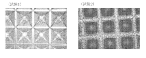
- a photograph of a state in which spheres are formed using a microwell plate from which bubbles have been removed by the medium filling solution according to the embodiment of the present invention (Test 1), and a state in which spheres are formed using a microwell plate in which bubbles remain It is a figure which shows the photograph (test 2). It is a schematic diagram which shows the culture medium filling method which concerns on embodiment of this invention. It is a schematic diagram which shows the culture medium filling method of the reference example 1. It is a schematic diagram which shows the culture medium filling method of the reference example 2.
- the medium-filling liquid of the present embodiment is a medium-filling liquid that removes air bubbles accumulated in the recesses before filling the medium when the culture container having a culture surface having a plurality of recesses is filled with the medium. And is degassed.
- Degassing means discharging the dissolved air in the liquid
- degassing above means a state in which the air dissolved in the medium filling solution has been removed to a certain extent. Means that. Deaeration can be performed by methods such as depressurization, heating, and ultrasonic waves. Degassing by depressurization is a method in which the liquid is boiled by lowering the atmospheric pressure to remove the air dissolved in the liquid. The relationship between the degree of vacuum due to reduced pressure and the boiling temperature of water is as follows.
- the container containing the medium filling solution is put in a vacuum chamber to reduce the pressure, and the vacuum degree of 20 Torr (2.67 kPa) is maintained for about 1 minute to dissolve the dissolved air in the medium filling solution.
- the amount can be 10% or less.
- the medium-filled liquid of the present embodiment is preferably degassed to have a dissolved air content of 50% or less, more preferably 10% or less.
- the medium filling solution of the present embodiment is preferably a medium, physiological saline, or one obtained by degassing any of the phosphate buffer, as long as it does not adversely affect the subsequent culture. It is not particularly limited. Here, it was found that when the medium-filling liquid contained a protein, bubbles were removed from the recesses of the culture container and the surface of the recesses was once wetted by the medium-filling liquid, and then the state was easily maintained. For this reason, it is preferable to use a medium as the medium filling solution, and it is also preferable to use a solution in which a protein such as albumin is dissolved in physiological saline or a phosphate buffer.
- the medium filling liquid of the present embodiment is preferably enclosed in a container having a gas barrier property. Specifically, for example, it is preferably sealed in a container made of glass, an aluminum pack, or the like. If the medium filling liquid of the present embodiment has such a configuration, it can be suitable for long-term storage.
- the culture object may be single cells (single cells), spheres (spheroids, aggregates), organoids, etc., and is not particularly limited as long as it can be cultured.
- FIG. 1 a photograph of a state immediately after filling the microwell plate with the medium is shown in FIG.
- the photograph on the left shows a microwell plate with box-shaped (square columnar) wells
- the photograph on the right shows a microwell plate with wells in the shape of a pyramid.
- One side of the openings of these recesses is 0.2 mm.
- the bubbles have a spherical shape
- the bubbles in the quadrangular pyramid wells, the bubbles have a quadrangular pyramid shape. The reason is that in a box-shaped well, the bubbles are spherical and the size is accommodated in the well, whereas in the square pyramid well, the bubbles are spherical and cannot be accommodated in the well. It is thought to be housed in a different shape.
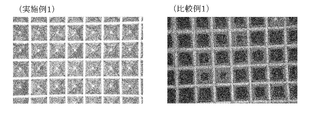
- Example 1 two microwell plates provided with square pyramidal wells were prepared, one of which was filled with the medium filling solution according to the present embodiment (Example 1), and the other was filled with the medium (Comparative Example). 1), the state which left still for 12 hours is shown in FIG. 2 (details are mentioned later in an Example). As a result, it can be seen that air bubbles were completely removed in the microwell plate of Example 1. On the other hand, in the microwell plate of Comparative Example 1, although some of the bubbles naturally disappeared, they were not completely removed, and many bubbles remained in the wells.
- the medium filling liquid of the present embodiment it is possible to efficiently remove the air bubbles that have accumulated in the minute recesses of the culture container. It is also easy to apply this to a culture vessel with a large culture surface. Furthermore, since it is not necessary to use a conventional vibration device or the like, it is possible to eliminate the risk of contaminating the surroundings.
- the above-mentioned medium filling liquid is filled in a culture vessel having a culture surface in which a plurality of recesses are formed and left to stand for a certain period of time, and then the medium is passed through the culture vessel, It is characterized in that the medium filling solution is replaced with a medium.
- the diameter of the circle or the inscribed circle of the openings in the plurality of recesses of the culture container is preferably 2 mm or less, more preferably 1.5 mm or less, and further preferably 1.0 mm or less. preferable. Further, it may be 0.5 mm or less, 0.2 mm or less, 0.1 mm or less, etc., but 0.3 mm to 0.5 mm is particularly preferable.
- the shape of the opening in the recess may be a circle or a polygon. Therefore, the diameter of the circle inscribed in the polygon is included as these diameters.
- the degassed medium-filled liquid does not contain oxygen necessary for culturing and is not suitable for culturing. Therefore, it is desirable to discharge the medium-filling liquid from the culturing vessel after the removal of air bubbles is completed. Therefore, in the medium filling method of the present embodiment, the medium filling liquid is filled in the culture container and allowed to stand for a certain period of time, and after the removal of air bubbles is completed, the medium filling liquid is passed by passing the medium through the culture container. The medium is mixed and the medium filling solution is gradually replaced with the medium.
- the medium filling liquid is filled in the culture container in advance before the start of culture to remove air bubbles.
- the reason is that in the method using the degassed medium filling solution of the present embodiment, the bubbles do not disappear immediately and it takes a certain time to remove the bubbles.
- the medium-filling bubble removing device of the present embodiment when filling a culture medium having a culture surface having a plurality of recesses formed therein, prior to filling the medium, the medium filling for removing bubbles accumulated in the recesses
- a bubble removing device for vacuum comprising a vacuum evacuation device, and after filling the culture container with a medium filling liquid, the culture container is placed in the vacuum evacuation device in a state of being filled with the medium filling liquid, and the evacuation is performed.
- the medium-filling bubble removing device 1 of the present embodiment includes a vacuum exhaust device, and the vacuum exhaust device includes a vacuum chamber 10, a vacuum pump 11, and an atmosphere opening valve 12. , And a filter device 13.
- the vacuum chamber 10 has a sterilizing function
- the atmosphere opening valve 12 is provided by being connected to a piping member between the vacuum chamber 10 and the vacuum pump 11. This sterilization function can be performed by, for example, a UV lamp or dry heat sterilization at 160 ° C. for 2 hours.
- the filter device 13 is provided at the end of the piping member provided with the atmosphere release valve 12.
- the medium-filling bubble removing device of the present embodiment performs vacuuming by the vacuum pump 11 so that the amount of dissolved air in the medium filling liquid of the culture container housed in the vacuum chamber 10 is 50% or less.
- the medium filling method of the present embodiment when filling a culture medium having a culture surface in which a plurality of recesses are formed, with a medium, a method of filling a medium that removes bubbles accumulated in the recesses prior to filling the medium. That is, after the culture container is filled with the medium filling liquid, the culture container is placed in an evacuation device with the medium filling liquid filled therein, and a vacuum is drawn so that the dissolved air amount in the medium filling liquid is 50% or less. It is also preferable to adopt a method of performing.
- the culture container is placed in a vacuum exhaust device so that the culture surface is horizontal, and the culture container is pressed by a pressing plate to perform vacuuming.
- a pressure plate that moves up and down along a guide pin is placed on the upper surface of the culture vessel, and the culture vessel is fixed so as to be pressed with a constant pressure by the weight of the pressure plate, and vacuuming can be performed.
- it can be realized by installing a spring material on the guide pin and appropriately pressing the pressing plate against the culture container. If the medium filling method of the present embodiment is such a method, it is possible to appropriately remove bubbles from all the recesses of the culture container even when the size of the culture container is relatively large.
- the culture container of the present embodiment is a culture container having a culture surface having a plurality of recesses used in the medium filling method of the present embodiment, and the culture container is a closure made of a soft packaging material. It is preferable that the system culture bag has a port to which a tube is connected and a filter is provided at the end of the tube.
- the culture container 2 of the present embodiment includes a large number of minute recesses 21 in the container body 20 and also a port 22.
- a tube 23 is connected to the port 22 and a filter device 24 is arranged at the other end.
- the filter device 24 is equipped with a sterile filter 241.
- a sterile filter 241 for example, a membrane filter having pores of 0.2 ⁇ m or 0.45 ⁇ m, a porous membrane, or the like can be used.
- the diameter of the circle or the inscribed circle of the opening in the recess 21 of the culture container 2 of the present embodiment is preferably 2 mm or less, more preferably 1.5 mm or less, and 1.0 mm or less. Is more preferable. Further, it may be 0.5 mm or less, 0.2 mm or less, 0.1 mm or less, etc., but 0.3 mm to 0.5 mm is particularly preferable.
- the depth of the recess 21 of the culture container 2 of the present embodiment is preferably 2 mm or less, more preferably 1.5 mm or less, further preferably 1.0 mm or less, and 0.3 mm. It is particularly preferable to set the thickness to 0.5 mm. No through hole is formed in the recess 21.
- the material of the culture vessel 2 of the present embodiment includes polyethylene, ethylene- ⁇ -olefin copolymer, cyclic olefin copolymer, ethylene-vinyl acetate copolymer, ionomer, ethylene / acrylic acid copolymer or methacrylic acid copolymer / metal. Examples thereof include ionomers using ions. Further, polyolefin, styrene-based elastomer, polyester-based thermoplastic elastomer, silicone-based thermoplastic elastomer, silicone resin and the like can also be used.
- thermoplastic elastomer a polyurethane-based thermoplastic elastomer, a polyester-based thermoplastic elastomer, a silicone-based thermoplastic elastomer, a styrene-based elastomer, a fluororesin, or the like, or a combination thereof, and it is particularly preferable to use a polyethylene-based resin.
- the culture container 2 is housed in the vacuum chamber 10 of the medium-filling air bubble removal apparatus of the present embodiment, and the culture container 2 is evacuated, whereby the medium filling liquid in the culture container 2 is deaerated and the air bubbles are removed from the recess 21. It is like this. At this time, since there is no pressure difference between the inside and the outside of the culture container 2 in the vacuum chamber, the container does not burst.
- the culture container 2 shown in FIG. 4 when the culture container 2 shown in FIG. 4 is filled with the medium filling liquid to such an extent that half of the culture surface is immersed in the culture surface in an upright state and vacuuming is performed, the culture medium filling liquid causes the culture surface to undergo a capillary phenomenon. Air bubbles are removed from the recess 21 by being transmitted to the whole and wetting the recess 21 with the medium filling liquid, and discharged to the outside of the culture container 2 through the tube 23.
- a vacuuming method using the medium-filling bubble removing device of the present embodiment as compared with the degassing method using the medium filling liquid of the present embodiment described above, it is possible to remove the bubbles in the concave portion in an extremely short time. It is possible to
- the culture container is not limited to the culture container of the present embodiment, and a culture container having a recessed portion such as a petri dish can be used. Even in this case, it is possible to efficiently remove bubbles from the recess of the culture container by using the medium-filling bubble removing device of the present embodiment. Further, in this case, air is taken in and out in the gap between the petri dish main body and the lid, and basically it is possible to remove the air from the gap without causing pollution unless the atmosphere is exposed to an extremely strong atmosphere.
- the vacuum chamber 10 in the air bubble removal apparatus for filling a medium of the present embodiment with a deaeration module
- the medium filling liquid is passed through the deaeration module to perform vacuuming, and the medium filling liquid is deaerated. It is also possible to adopt a configuration that does.
- the medium filling solution of this embodiment was prepared as follows. 500 mL of the medium (StemFit AK02N (Ajinomoto Co., Inc., product number RCAK02N)) was placed in a 1 L bottle, and this was left standing in a vacuum exhaust device (Yamato Scientific Co., Ltd., ADP300) for evacuation. The evacuation was carried out by holding at a vacuum degree of 20 Torr at room temperature of 22 ° C. for about 1 minute. As a result, a medium-filled solution that had been degassed to have a dissolved air content of 10% or less was obtained.
- a vacuum exhaust device Yamamoto Co., Ltd., ADP300
- the obtained medium filling solution was filled in a microwell plate (Kuraray Co., Ltd., product number SQ200) and left standing for 12 hours.
- the microwell plate was provided with a plurality of quadrangular pyramidal recesses, the opening of each recess was 0.2 mm on a side, and the depth of the recess was 0.5 mm.
- a photograph of the recesses in the microwell plate immediately after being filled with the medium filling solution is shown in FIG. 1 (right side).
- a photograph of the recesses in the microwell plate after 12 hours has elapsed is shown in FIG. 2 (Example 1).
- Test 1 a test for forming spheres using the microwell plate from Example 1 in which air bubbles are removed will be described. Specifically, StemFit AK02N (Ajinomoto Co., Inc., product number RCAK02N) containing 10 mM Y-27632 (Wako Pure Chemical Industries, Ltd.) was passed through this microwell plate, and the medium filling solution used for degassing was passed. The medium was replaced.
- iPS cells (1231A3 strain) were seeded so as to be housed in each recess of this microwell plate, and cultured for 48 hours to form spheres.
- the results are shown in Fig. 5 (Test 1). As shown in the figure, it can be seen that a sphere is formed in each recess. As described above, it was clarified that the spheres can be preferably formed by using the microwell plate from which air bubbles have been removed by the medium filling liquid of the present embodiment.
- Test 2 Next, a test for forming spheres using the microwell plate of Comparative Example 1 in which bubbles are not removed will be described. Specifically, 10 mM Y-27632 (Wako Pure Chemical Industries, Ltd.) was added to the medium of this microwell plate and seeded so that 500 iPS cells (1231A3 strain) were housed in each recess. The cells were cultured for 48 hours to form spheres. The results are shown in Fig. 5 (Test 2). As shown in the figure, since air bubbles were accumulated in each recess, many cells were deposited on the culture surface between the recesses, and spheres could not be properly formed.
- Example 2 As the culture container, the one shown in the culture container 2 in FIG. 4 was prepared. Polyethylene (Toyo Seikan culture bag) was used as a material for the culture container, and two 100 mm ⁇ 70 mm films were prepared. On the culture surface of the culture vessel, recesses having an opening diameter of 0.3 mm and a depth of 0.2 mm were formed at intervals of 0.4 mm. Then, the film on which the culture surface was formed and the other film were bonded by heat sealing. At this time, one port was formed, and a sterile filter (0.45 ⁇ m membrane filter 723-2545, manufactured by Thermo Fisher Scientific) was connected to this port via a tube.
- a sterile filter (0.45 ⁇ m membrane filter 723-2545, manufactured by Thermo Fisher Scientific
- a medium (StemFit AK02N (Ajinomoto Co., Inc., product number RCAK02N)) was filled into this culture container as a medium filling liquid so that about half of the culture surface was immersed with the culture surface standing upright. Then, with the culture surface standing upright as it was, the culture surface was allowed to stand still in a vacuum exhaust device (Yamato Scientific Co., Ltd., ADP300) to perform evacuation. The evacuation was carried out by holding at a vacuum degree of 20 Torr at room temperature of 22 ° C. for about 1 minute. Thereby, the amount of dissolved air in the medium filling liquid can be reduced to 10% or less. As a result, the medium-filling liquid was transferred to the entire culture surface by capillarity, and the recesses were wet with the medium-filling liquid, whereby the bubbles could be removed from all the recesses.
- Example 3 A culture container having the same structure as in Example 2 and a larger size was prepared. Polyethylene (Toyo Seikan culture bag) was used as a material for the culture container, and two 300 mm ⁇ 200 mm films were prepared. On the culture surface of the culture vessel, recesses having an opening diameter of 0.3 mm and a depth of 0.2 mm were formed at intervals of 0.4 mm. Then, the film on which the culture surface was formed and the other film were bonded by heat sealing. At this time, one port was formed, and a sterile filter ((0.45 ⁇ m membrane filter 723-2545, manufactured by Thermo Fisher Scientific) was connected to this port via a tube.
- a sterile filter ((0.45 ⁇ m membrane filter 723-2545, manufactured by Thermo Fisher Scientific) was connected to this port via a tube.
- This culture vessel was filled with a predetermined amount of medium (StemFit AK02N (Ajinomoto Co., Inc., product number RCAK02N)) as a medium filling solution. Then, it was left standing in a vacuum exhaust device (Yamato Scientific Co., Ltd., ADP300) to perform vacuuming. The evacuation was carried out by holding at a vacuum degree of 20 Torr at room temperature of 22 ° C. for about 1 minute. Thereby, the amount of dissolved air in the medium filling liquid can be reduced to 10% or less.
- a vacuum exhaust device Yamaato Scientific Co., Ltd., ADP300
- the culture container was placed in a vacuum exhaust device so that the culture surface of the culture container was horizontal. Then, a pressing plate 4 having a weight of 2 kg which moves up and down along the guide pins 5 was placed on the upper surface of the culture container, and the culture container was fixed so as to be pressed with a constant pressure by its own weight.
- the gas generated by the boiling of the medium-filled liquid 3 moves upward in the culture container as a group of relatively large air bubbles having a diameter of about 50 mm, and the large air bubbles 6 thus collected are attracted by the port side pulling pressure. , Was discharged from the culture container via the port.
- the pressing plate moved up and down along with the generation of gas and the discharge from the port. Further, when the generation of gas from the medium filling liquid 3 was completed, the pressing plate was stopped, and the air bubbles were removed from all the recesses in the culture container.
- Example 1 Using the culture vessel prepared in Example 3, evacuation was performed in a mode different from that of Example 3. Specifically, as shown in FIG. 7, a culture medium (StemFit AK02N (Ajinomoto Co., Inc., Part number RCAK02N)) was filled. In addition, in FIG. 7, the concave portion formed on the culture surface of the culture container is omitted.
- a culture medium StemFit AK02N (Ajinomoto Co., Inc., Part number RCAK02N)
- the culture surface was allowed to stand still in a vacuum exhaust device (Yamato Scientific Co., Ltd., ADP300) to perform vacuuming.
- the evacuation was carried out by holding at a vacuum degree of 20 Torr at room temperature of 22 ° C. for about 1 minute.
- the medium filling liquid could not be transferred to the entire culture surface of the culture container, and it was not possible to remove the air bubbles in all the recesses. That is, when the size of the culture vessel is large, a large amount of the medium filling liquid necessary for wetting the entire culture surface is required accordingly. However, when the culture surface is set upright, the medium is filled with the medium as shown in FIG. A lot of filling liquid accumulates in the lower part. For this reason, the two films were separated from each other, and the capillary phenomenon did not occur, and it was not possible to remove the bubbles in the upper recesses that were not immersed in the medium filling solution.
- Example 2 Using the culture vessel prepared in Example 3, evacuation was performed in a mode different from that of Example 3. Specifically, this culture vessel was filled with a predetermined amount of medium (StemFit AK02N (Ajinomoto Co., Inc., product number RCAK02N)) as a medium filling solution. Then, as shown in FIG. 8, the culture surface was placed in a vacuum exhaust device (Yamato Scientific Co., Ltd., ADP300) so that the culture surface was horizontal, and vacuuming was performed. The evacuation was carried out by holding at a vacuum degree of 20 Torr at room temperature of 22 ° C. for about 1 minute. In addition, in FIG. 8, the concave portion formed on the culture surface of the culture container is omitted.
- a vacuum exhaust device Yamamoto Co., Ltd., ADP300
- the gas generated by the boiling of the medium-filled liquid accumulates in the center of the culture container and the culture container swells significantly, and the gas cannot be properly discharged from the port, and the bubbles are sufficiently removed from the recess of the culture container.
- I could't. That is, since there is no pressing plate, the collected bubbles are gathered in the center and the port is blocked by the medium filling liquid 3, and the bubbles cannot move to the port side. Then, the pressure difference between the inside and the outside of the culture container increases, and the bubbles expand to such an extent that the film material in the culture container is stretched, and the bubbles cannot be discharged.
- the culture container When the size of the culture container is relatively large, the culture container is left to stand in an evacuation device so that the culture surface is horizontal, and the culture medium filling liquid boils to the center of the culture container.
- the culture medium filling solution As described above, according to the culture medium filling solution, the culture medium filling method, the culture container, and the culture medium-filling bubble removing device of the present invention, when the cells are cultured using the culture container having the fine recesses, the cells are accumulated in the fine recesses.
- the bubbles can be removed efficiently, and the bubbles can be applied to a culture vessel having a large culture surface.
- the present invention is not limited to the above embodiments and examples, and various modifications can be made within the scope of the present invention.
- the culture container can be appropriately changed, for example, a culture container having a size capable of forming 500,000 to 1 million spheres can be used.
- the present invention can be suitably used when efficiently producing a large amount of culture objects such as spheres.
- Bubble removing device for medium filling 10 Vacuum chamber 11 Vacuum pump 12 Air release valve 13 Filter device 2,2a Culture container 20, 20a Container body 21 Recess 22 Port 23 Tube 24, 24a Filter device 241 Sterile filter 3 Medium filling liquid 4 Pressing Board 5 Guide pin 6 Bubble
Landscapes
- Engineering & Computer Science (AREA)
- Life Sciences & Earth Sciences (AREA)
- Health & Medical Sciences (AREA)
- Chemical & Material Sciences (AREA)
- Bioinformatics & Cheminformatics (AREA)
- Wood Science & Technology (AREA)
- Organic Chemistry (AREA)
- Zoology (AREA)
- Biotechnology (AREA)
- General Engineering & Computer Science (AREA)
- Genetics & Genomics (AREA)
- Biomedical Technology (AREA)
- Biochemistry (AREA)
- General Health & Medical Sciences (AREA)
- Microbiology (AREA)
- Sustainable Development (AREA)
- Medicinal Chemistry (AREA)
- Virology (AREA)
- Cell Biology (AREA)
- Tropical Medicine & Parasitology (AREA)
- Mechanical Engineering (AREA)
- Apparatus Associated With Microorganisms And Enzymes (AREA)
- Micro-Organisms Or Cultivation Processes Thereof (AREA)
Abstract
微小凹部を有する培養容器を用いて細胞を培養するにあたり、微小凹部に溜まった気泡を効率よく除去することを可能とし、またこれを培養面の大きな培養容器に適用することを可能とする。複数の凹部が形成された培養面を有する培養容器に培地を充填する際に、培地の充填に先立って、凹部に溜まった気泡を除去する培地充填液であって、脱気されている培地充填液とする。このような培地充填液を、複数の凹部が形成された培養面を有する培養容器に充填して一定時間静置させ、ついで培養容器に培地を通液して、培地充填液を培地に置き換える。
Description
本発明は、細胞培養技術に関し、特に微小な凹部を備えた培養容器を用いて培養を行う技術に関する。
近年、iPS細胞やES細胞などの幹細胞等の接着細胞を大量に培養する場合には、細胞を培養容器に接着させて増殖させるだけではなく、細胞に対して接着性の低い材料を塗工したマイクロウェルプレートなどの培養容器を使用して、スフェア(スフェロイド,凝集塊)を形成させることによって、細胞をより生体内に近い三次元的な状態で培養する方法が用いられている。
このような培養では、微小な凹部(ウェル)が多数形成されている培養容器が用いられる場合がある。ところが、この培養容器に培地を充填すると、微小凹部に気泡が閉じ込められて溜まってしまい、細胞培養に支障が出るという問題があった。すなわち、微小凹部に気泡が残ると、スフェアの形成が阻害されてしまうが、微小凹部から全ての気泡を除去することは、極めて困難であった。
ここで、微小凹部に溜まった気泡を除去するために、マイクロピペットなどを用いて気泡に液を拭きかけることにより、水圧で気泡を除去することが行われている。
しかしながら、このようなピペットによる操作では気泡を除去できない場合があった。
しかしながら、このようなピペットによる操作では気泡を除去できない場合があった。
すなわち、このようなピペット操作による方法では、凹部の開口部の直径が1mm以下の場合には、気泡を除去することが難しく、凹部の開口部の直径が0.2mm以下の場合には、気泡を除去することが非常に困難であった。
また、この方法では、たとえ気泡を除去できても、培養容器の培養面が大きい場合には、非常に手間がかかり、また培養容器を長時間開放させた状態での操作が必要になるため、培養容器内を汚染する危険性が高くなるという問題もあった。
また、この方法では、たとえ気泡を除去できても、培養容器の培養面が大きい場合には、非常に手間がかかり、また培養容器を長時間開放させた状態での操作が必要になるため、培養容器内を汚染する危険性が高くなるという問題もあった。
このような問題の解消に関連する技術として、特許文献1に記載の加振装置を挙げることができる。
この加振装置には、培養容器を底面と直交する方向へ加振する加振部が備えられており、培養容器に振動を与えることによって、培養容器の凹部に溜まった気泡を除去する構成となっている。
このような加振装置によれば、気泡の大きさや形状によってはこれを除去することができるが、一方で振動だけでは除去できない場合があった。また、培養容器の培養面が大きい場合には手間がかかり、加振装置を用いるためのコストが必要になるという問題があった。さらに、振動によって培養容器から液が飛び出し、周辺に培地をこぼす危険性もあった。
この加振装置には、培養容器を底面と直交する方向へ加振する加振部が備えられており、培養容器に振動を与えることによって、培養容器の凹部に溜まった気泡を除去する構成となっている。
このような加振装置によれば、気泡の大きさや形状によってはこれを除去することができるが、一方で振動だけでは除去できない場合があった。また、培養容器の培養面が大きい場合には手間がかかり、加振装置を用いるためのコストが必要になるという問題があった。さらに、振動によって培養容器から液が飛び出し、周辺に培地をこぼす危険性もあった。
また、特許文献2に記載のマイクロウェルプレート用撹拌・脱泡装置を挙げることもできる。この装置によれば、マイクロウェルプレートを公転及び自転させることにより、マイクロウェルプレートのウェル内の溶液を同時に均一に撹拌して、溶液中の微小な気泡を除去することを可能としている。
この撹拌・脱泡装置によれば、直径が約2mm程度のウェル(1536ウェル)の場合は、気泡を除去できるが、直径が1mm以下のウェルや、さらに直径が0.2mm以下のウェルに対しては、この装置のような遠心による方法では、気泡を完全に除去することは難しかった。
この撹拌・脱泡装置によれば、直径が約2mm程度のウェル(1536ウェル)の場合は、気泡を除去できるが、直径が1mm以下のウェルや、さらに直径が0.2mm以下のウェルに対しては、この装置のような遠心による方法では、気泡を完全に除去することは難しかった。
また、これらの従来の方法や装置では、A4サイズなどの大きな培養面を有する培養容器の凹部から気泡を除去する場合には、適用することが難しかった。
そこで、本発明者らは鋭意研究し、培養容器に培地を充填するのに先だって、培養容器にまず脱気した培地充填液を充填して一定時間静置させることにより、培養容器における微小凹部に溜まった気泡を効率よく除去できることを見いだした。
また、培養容器に培地を充填するのに先だって、培養容器に培地充填液を充填した後、真空排気装置により培養容器を真空にさらすことにより、培養容器における微小凹部に溜まった気泡を効率よく除去できることを見いだした。
さらに、これらの方法によれば、培養面の大きな培養容器にも容易に適用することが可能であるため、スフェアなどの大量培養に好適に用いることが可能となる。
また、培養容器に培地を充填するのに先だって、培養容器に培地充填液を充填した後、真空排気装置により培養容器を真空にさらすことにより、培養容器における微小凹部に溜まった気泡を効率よく除去できることを見いだした。
さらに、これらの方法によれば、培養面の大きな培養容器にも容易に適用することが可能であるため、スフェアなどの大量培養に好適に用いることが可能となる。
本発明は、上記事情に鑑みてなされたものであり、微小凹部を有する培養容器を用いて細胞を培養するにあたり、微小凹部に溜まった気泡を効率よく除去することができ、また培養面の大きな培養容器に容易に適用することが可能な培地充填液、培地充填方法、培養容器、及び培地充填用気泡除去装置の提供を目的とする。
上記目的を達成するため、本発明の培地充填液は、複数の凹部が形成された培養面を有する培養容器に培地を充填する際に、培地の充填に先立って、前記凹部に溜まった気泡を除去する培地充填液であって、脱気されている構成としてある。
また、本発明の培地充填方法は、上記の培地充填液を、複数の凹部が形成された培養面を有する培養容器に充填して一定時間静置させ、ついで前記培養容器に培地を通液して、前記培地充填液を培地に置き換える方法としてある。
また、本発明の培地充填方法は、複数の凹部が形成された培養面を有する培養容器に培地を充填する際に、培地の充填に先立って、前記凹部に溜まった気泡を除去する培地充填方法であって、前記培養容器に培地充填液を充填した後、前記培地充填液を充填した状態で前記培養容器を真空排気装置に入れて、前記培地充填液における溶存空気量が50%以下になるように真空引きを行う方法としてある。
また、本発明の培養容器は、上記の培地充填方法に用いられる複数の凹部が形成された培養面を有する培養容器であって、前記培養容器が、軟包材からなる閉鎖系の培養バッグであり、チューブを接続したポートを有し、前記チューブの端部にフィルタを備えた構成としてある。
また、本発明の培地充填用気泡除去装置は、複数の凹部が形成された培養面を有する培養容器に培地を充填する際に、培地の充填に先立って、前記凹部に溜まった気泡を除去する培地充填用気泡除去装置であって、真空排気装置を備え、前記培養容器に培地充填液を充填した後、前記培地充填液を充填した状態で前記培養容器を前記真空排気装置に入れて真空引きを行う構成としてある。
本発明によれば、微小凹部を有する培養容器を用いて細胞を培養するにあたり、微小凹部に溜まった気泡を効率よく除去することができ、また培養面の大きな培養容器に容易に適用することが可能な培地充填液、培地充填方法、培養容器、及び培地充填用気泡除去装置の提供が可能となる。
以下、本発明の培地充填液、培地充填方法、培養容器、及び培地充填用気泡除去装置の実施形態について詳細に説明する。ただし、本発明は、以下の実施形態及び実施例の具体的な内容に限定されるものではない。
まず、本発明の実施形態に係る培地充填液について詳細に説明する。
本実施形態の培地充填液は、複数の凹部が形成された培養面を有する培養容器に培地を充填する際に、培地の充填に先立って、凹部に溜まった気泡を除去する培地充填液であって、脱気されていることを特徴とする。
本実施形態の培地充填液は、複数の凹部が形成された培養面を有する培養容器に培地を充填する際に、培地の充填に先立って、凹部に溜まった気泡を除去する培地充填液であって、脱気されていることを特徴とする。
「脱気」とは、液体中の溶存空気を排出することであり、上記の「脱気されている」とは、培地充填液に溶存していた空気が一定程度まで除去された状態であることを意味する。
脱気は、減圧、加熱、超音波等の方法により行うことができる。減圧による脱気は、気圧を低くすることによって液体を沸騰させ、液体中に溶存していた空気を除去する方法である。減圧による真空度と水の沸騰する温度との関係は、以下の通りである。
脱気は、減圧、加熱、超音波等の方法により行うことができる。減圧による脱気は、気圧を低くすることによって液体を沸騰させ、液体中に溶存していた空気を除去する方法である。減圧による真空度と水の沸騰する温度との関係は、以下の通りである。
<水の沸騰する温度> <真空度>
100.0℃ 760 Torr
51.3℃ 100 Torr
37.8℃ 50 Torr
22.0℃ 20 Torr
17.5℃ 15 Torr
11.4℃ 10 Torr
7.9℃ 8 Torr
(1Torr≒133Pa)
100.0℃ 760 Torr
51.3℃ 100 Torr
37.8℃ 50 Torr
22.0℃ 20 Torr
17.5℃ 15 Torr
11.4℃ 10 Torr
7.9℃ 8 Torr
(1Torr≒133Pa)
例えば、室温が22℃の場合、培地充填液を収容した容器を真空チャンバに入れて減圧し、20Torr(2.67kPa)の真空度で、1分程度保持することによって、培地充填液における溶存空気量を10%以下にすることができる。
本実施形態の培地充填液は、溶存空気量が50%以下に脱気されていることが好ましく、10%以下に脱気されていることがより好ましい。
本実施形態の培地充填液は、溶存空気量が50%以下に脱気されていることが好ましく、10%以下に脱気されていることがより好ましい。
本実施形態の培地充填液は、培地、生理食塩水、又はリン酸緩衝液のいずれかを脱気させて得られたものとすることが好ましく、その後の培養に悪影響を及ぼさないものであれば、特に限定されない。
ここで、培地充填液にタンパク質が含まれていると、培養容器の凹部から気泡が除去されて凹部の表面が一旦培地充填液によって濡れた後に、その状態を保持しやすいことが分かった。このため、培地充填液としては、培地を用いることが好ましく、また生理食塩水やリン酸緩衝液に例えばアルブミンなどのタンパク質を溶解したものを用いることも好ましい。
ここで、培地充填液にタンパク質が含まれていると、培養容器の凹部から気泡が除去されて凹部の表面が一旦培地充填液によって濡れた後に、その状態を保持しやすいことが分かった。このため、培地充填液としては、培地を用いることが好ましく、また生理食塩水やリン酸緩衝液に例えばアルブミンなどのタンパク質を溶解したものを用いることも好ましい。
また、本実施形態の培地充填液は、ガスバリア性を有する容器に封入されたものとすることが好ましい。具体的には、例えば、ガラスやアルミパックなどからなる容器に封入されたものとすることが好ましい。
本実施形態の培地充填液をこのような構成にすれば、長期保存に適したものとすることができる。
本実施形態の培地充填液をこのような構成にすれば、長期保存に適したものとすることができる。
なお、本実施形態において、培養対象物としては、シングルセル(単一細胞)やスフェア(スフェロイド,凝集塊)、オルガノイド等とすることができ、培養可能なものであればよく、特に限定されない。
ここで、マイクロウェルプレートに培地を充填した直後の状態の写真を図1に示す。
左側の写真は、箱形(四角柱状)のウェルを備えたマイクロウェルプレートを示し、右側の写真は、四角錐状のウェルを備えたマイクロウェルプレートを示す。これらの凹部の開口部の一辺は、0.2mmである。
これらの図に示すように、いずれの写真でも全てのウェルに気泡が溜まっていることが分かる。
左側の写真は、箱形(四角柱状)のウェルを備えたマイクロウェルプレートを示し、右側の写真は、四角錐状のウェルを備えたマイクロウェルプレートを示す。これらの凹部の開口部の一辺は、0.2mmである。
これらの図に示すように、いずれの写真でも全てのウェルに気泡が溜まっていることが分かる。
なお、箱形のウェルでは気泡は球状を示し、四角錐状のウェルでは気泡は四角錐状を示している。その理由は、箱形のウェルでは気泡が球状でウェルに収容されるサイズである一方、四角錐状のウェルでは気泡が球状でウェルに収容できないサイズであるため、表面張力によりウェルの壁面に沿った形状で収容されていると考えられる。
次に、四角錐状のウェルを備えたマイクロウェルプレートを2枚用意し、一方に本実施形態に係る培地充填液を充填し(実施例1)、もう一方に培地を充填して(比較例1)、12時間静置させた状態を図2に示す(詳細については、実施例において後述する)。
その結果、実施例1のマイクロウェルプレートでは、気泡が完全に除去されたことが分かる。これに対して、比較例1のマイクロウェルプレートでは、気泡の一部が自然になくなっているものの、完全には除去されてはおらず、多くの気泡がウェルに残存していることが分かる。
その結果、実施例1のマイクロウェルプレートでは、気泡が完全に除去されたことが分かる。これに対して、比較例1のマイクロウェルプレートでは、気泡の一部が自然になくなっているものの、完全には除去されてはおらず、多くの気泡がウェルに残存していることが分かる。
このように本実施形態の培地充填液によれば、培養容器の微小凹部に溜まった気泡を効率よく除去することが可能である。また、これを培養面の大きな培養容器に適用することも容易である。さらに、従来の加振装置などを用いる必要がないため、周辺を汚染する危険性を排除することも可能となっている。
本実施形態の培地充填方法は、上記の培地充填液を、複数の凹部が形成された培養面を有する培養容器に充填して一定時間静置させ、ついで培養容器に培地を通液して、培地充填液を培地に置き換えることを特徴とする。
このとき、培養容器の複数の凹部における開口部の円又は内接円の直径は、2mm以下であることが好ましく、1.5mm以下であることがより好ましく、1.0mm以下であることがさらに好ましい。また、0.5mm以下、0.2mm以下、0.1mm以下等にしてもよいが、0.3mm~0.5mmとすることが特に好ましい。
なお、凹部における開口部の形状は、円や多角形の場合がある。そのため、これらの直径として、多角形に内接する円の直径を含めている。
なお、凹部における開口部の形状は、円や多角形の場合がある。そのため、これらの直径として、多角形に内接する円の直径を含めている。
ここで、脱気した培地充填液は、培養に必要な酸素が含まれておらず、培養には適さないため、気泡の除去が完了した後、培養容器から排出することが望ましい。
そこで、本実施形態の培地充填方法では、培地充填液を培養容器に充填して一定時間静置させ、気泡の除去が完了した後に、培養容器に培地を通液することによって、培地充填液を培地に混合し、培地充填液を培地に次第に置き換えていくようにしている。
そこで、本実施形態の培地充填方法では、培地充填液を培養容器に充填して一定時間静置させ、気泡の除去が完了した後に、培養容器に培地を通液することによって、培地充填液を培地に混合し、培地充填液を培地に次第に置き換えていくようにしている。
本実施形態の培地充填方法では、上記のように、培養を開始する時間の前に予め培養容器に培地充填液を充填して気泡を除去するようにしている。その理由は、本実施形態の脱気された培地充填液を用いる方法では、直ぐには気泡が消えず、気泡の除去に一定の時間がかかるためである。
本実施形態の培地充填用気泡除去装置は、複数の凹部が形成された培養面を有する培養容器に培地を充填する際に、培地の充填に先立って、凹部に溜まった気泡を除去する培地充填用気泡除去装置であって、真空排気装置を備え、培養容器に培地充填液を充填した後、培地充填液を充填した状態で培養容器を真空排気装置に入れて真空引きを行うことを特徴とする。
具体的には、図3に示すように、本実施形態の培地充填用気泡除去装置1は、真空排気装置を備えてなり、真空排気装置は、真空チャンバ10、真空ポンプ11、大気開放弁12、及びフィルタ装置13を有するものとすることが好ましい。
真空チャンバ10は滅菌機能を有しており、大気開放弁12は、真空チャンバ10及び真空ポンプ11の間の配管部材に接続して備えられている。この滅菌機能としては、例えば、UVランプや160℃,2時間の乾熱滅菌などによるものとすることができる。また、フィルタ装置13は、大気開放弁12が備えられた配管部材の端部に備えられている。
真空チャンバ10は滅菌機能を有しており、大気開放弁12は、真空チャンバ10及び真空ポンプ11の間の配管部材に接続して備えられている。この滅菌機能としては、例えば、UVランプや160℃,2時間の乾熱滅菌などによるものとすることができる。また、フィルタ装置13は、大気開放弁12が備えられた配管部材の端部に備えられている。
本実施形態の培地充填用気泡除去装置は、真空チャンバ10に収容された培養容器の培地充填液における溶存空気量が50%以下になるように、真空ポンプ11によって真空引きを行う。
そこで、本実施形態の培地充填方法を、複数の凹部が形成された培養面を有する培養容器に培地を充填する際に、培地の充填に先立って、凹部に溜まった気泡を除去する培地充填方法であって、培養容器に培地充填液を充填した後、培地充填液を充填した状態で培養容器を真空排気装置に入れて、培地充填液における溶存空気量が50%以下になるように真空引きを行う方法とすることも好ましい。
また、このとき、培養容器の培養面が水平になるように真空排気装置内に配置し、培養容器を押圧板により押圧して、真空引きを行うことも好ましい。
例えば、培養容器の上面にガイドピンに沿って上下移動する押圧板を載せ、この押圧板の自重により培養容器を一定の圧力で押圧するように固定して、真空引きを行うことができる。また、ガイドピンにバネ材を設置し、押圧板を培養容器に適宜押し付けることによって、実現することも可能である。
本実施形態の培地充填方法をこのような方法にすれば、培養容器のサイズが比較的大きい場合でも、培養容器の全ての凹部から気泡を適切に除去することが可能である。
例えば、培養容器の上面にガイドピンに沿って上下移動する押圧板を載せ、この押圧板の自重により培養容器を一定の圧力で押圧するように固定して、真空引きを行うことができる。また、ガイドピンにバネ材を設置し、押圧板を培養容器に適宜押し付けることによって、実現することも可能である。
本実施形態の培地充填方法をこのような方法にすれば、培養容器のサイズが比較的大きい場合でも、培養容器の全ての凹部から気泡を適切に除去することが可能である。
また、本実施形態の培養容器は、このような本実施形態の培地充填方法に用いられる複数の凹部が形成された培養面を有する培養容器であって、培養容器が、軟包材からなる閉鎖系の培養バッグであり、チューブを接続したポートを有し、チューブの端部にフィルタを備えた構成とすることが好ましい。
具体的には、図4に示すように、本実施形態の培養容器2は、容器本体20に多数の微小な凹部21を備え、またポート22を備えている。ポート22にはチューブ23が接続され、他方の端部にフィルタ装置24が配置されている。このフィルタ装置24には無菌フィルタ241が備えられている。
無菌フィルタ241としては、例えば0.2μmや0.45μmの孔を有するメンブレンフィルタや多孔質膜などを用いることができる。
無菌フィルタ241としては、例えば0.2μmや0.45μmの孔を有するメンブレンフィルタや多孔質膜などを用いることができる。
また、本実施形態の培養容器2の凹部21における開口部の円又は内接円の直径は、2mm以下であることが好ましく、1.5mm以下であることがより好ましく、1.0mm以下であることがさらに好ましい。また、0.5mm以下、0.2mm以下、0.1mm以下等にしてもよいが、0.3mm~0.5mmとすることが特に好ましい。
また、本実施形態の培養容器2の凹部21の深さは、2mm以下であることが好ましく、1.5mm以下であることがより好ましく、1.0mm以下であることがさらに好ましく、0.3mm~0.5mmとすることが特に好ましい。なお、凹部21において貫通孔は形成されていない。
本実施形態の培養容器2の材料としては、ポリエチレン、エチレン-α-オレフィンの共重合体、環状オレフィンコポリマー、エチレン-酢酸ビニル共重合体、アイオノマー、エチレンとアクリル酸やメタクリル酸共重合体と金属イオンを用いたアイオノマー等を挙げることができる。また、ポリオレフィン、スチレン系エラストマー、ポリエステル系熱可塑性エラストマー、シリコーン系熱可塑性エラストマー、シリコーン樹脂等を用いることもできる。さらに、ポリウレタン系熱可塑性エラストマー、ポリエステル系熱可塑性エラストマー、シリコーン系熱可塑性エラストマー、スチレン系エラストマー、フッ素系樹脂等、またはそれらを組み合わせて用いることが好ましく、ポリエチレン系樹脂を用いることが特に好ましい。
本実施形態の培地充填用気泡除去装置の真空チャンバ10に、培養容器2を収容して、真空引きすることで、培養容器2における培地充填液が脱気されて凹部21から気泡が除去されるようになっている。
このとき、真空チャンバ内において、培養容器2の内外で圧力差がないため、容器が破裂することはない。
このとき、真空チャンバ内において、培養容器2の内外で圧力差がないため、容器が破裂することはない。
また、図4に示す培養容器2に、培養面が直立した状態で、培養面の半分が浸漬する程度に培地充填液を充填して真空引きを行うと、培地充填液が毛細管現象により培養面全体に伝わり、凹部21が培地充填液により濡れることで、気泡が凹部21から除去されて、チューブ23を通じて培養容器2の外部へ排出される。
このような本実施形態の培地充填用気泡除去装置を用いる真空引き方式によれば、上述した本実施形態の培地充填液を用いる脱気方式に比較して、極めて短時間で凹部における気泡を除去することが可能である。
このような本実施形態の培地充填用気泡除去装置を用いる真空引き方式によれば、上述した本実施形態の培地充填液を用いる脱気方式に比較して、極めて短時間で凹部における気泡を除去することが可能である。
さらに、本実施形態の培地充填用気泡除去装置を用いるにあたり、培養容器としては、本実施形態の培養容器に限定されず、シャーレなどのリジッドで凹部を有する培養容器を使用することもできる。
この場合でも、本実施形態の培地充填用気泡除去装置を用いることで、培養容器の凹部から気泡を効率的に除去することが可能である。またこの場合、シャーレ本体と蓋の隙間で空気の出し入れが行われ、極端に強い大気開放をしない限り基本的には汚染することなく、隙間から空気を抜くことが可能になっている。
この場合でも、本実施形態の培地充填用気泡除去装置を用いることで、培養容器の凹部から気泡を効率的に除去することが可能である。またこの場合、シャーレ本体と蓋の隙間で空気の出し入れが行われ、極端に強い大気開放をしない限り基本的には汚染することなく、隙間から空気を抜くことが可能になっている。
また、本実施形態の培地充填用気泡除去装置における真空チャンバ10を、脱気モジュールで構成することによって、培地充填液を脱気モジュールに通液して真空引きを行い、培地充填液を脱気する構成とすることも可能である。
以下、本発明の実施形態に係る培地充填液、及びこれを用いた培地充填方法の実施例等、これらの効果を確認するために行った試験、並びに本発明の実施形態に係る培養容器、及びこれを用いた培地充填方法の実施例等について説明する。
(実施例1)
まず、本実施形態の培地充填液を次のように作成した。
培地(StemFit AK02N(味の素株式会社,品番RCAK02N))500mLを1Lのボトルに入れ、これを真空排気装置(ヤマト科学株式会社,ADP300)内に静置して真空引きを行った。真空引きは、室温22℃の状態で20Torrの真空度で、1分程度保持することにより行った。これにより、溶存空気量が10%以下に脱気された培地充填液を得た。
まず、本実施形態の培地充填液を次のように作成した。
培地(StemFit AK02N(味の素株式会社,品番RCAK02N))500mLを1Lのボトルに入れ、これを真空排気装置(ヤマト科学株式会社,ADP300)内に静置して真空引きを行った。真空引きは、室温22℃の状態で20Torrの真空度で、1分程度保持することにより行った。これにより、溶存空気量が10%以下に脱気された培地充填液を得た。
次に、得られた培地充填液をマイクロウェルプレート(株式会社クラレ,品番SQ200)に充填して、12時間静置させた。マイクロウェルプレートは、四角錐状の凹部を複数備えており、凹部の開口部は一辺0.2mm、凹部の深さは0.5mmであった。
培地充填液を充填した直後のマイクロウェルプレートにおける凹部の写真を図1(右側)に示す。また、12時間経過後のマイクロウェルプレートにおける凹部の写真を図2(実施例1)に示す。
培地充填液を充填した直後のマイクロウェルプレートにおける凹部の写真を図1(右側)に示す。また、12時間経過後のマイクロウェルプレートにおける凹部の写真を図2(実施例1)に示す。
これらの図に示されるように、培地充填液を充填した直後のマイクロウェルプレートでは、全ての凹部に気泡が溜まっていることが分かる。
これに対して、培地充填液を充填して12時間経過後のマイクロウェルプレートでは、全ての凹部から気泡が除去されていることが分かる。
このように、本実施形態の培地充填液によれば、微小凹部に溜まった気泡を効率よく除去できることが明らかとなった。
これに対して、培地充填液を充填して12時間経過後のマイクロウェルプレートでは、全ての凹部から気泡が除去されていることが分かる。
このように、本実施形態の培地充填液によれば、微小凹部に溜まった気泡を効率よく除去できることが明らかとなった。
(比較例1)
次に、脱気を行っていない通常の培地として、所定量のStemFit AK02N(味の素株式会社,品番RCAK02N)をマイクロウェルプレート(株式会社クラレ,品番SQ200)に充填して12時間静置させた。マイクロウェルプレートは、実施例1のものと同じである。
培地充填液を充填した直後のマイクロウェルプレートにおける凹部は、図1(右側)と同様の状態であった。また、12時間経過後のマイクロウェルプレートにおける凹部の写真を図2(比較例1)に示す。
次に、脱気を行っていない通常の培地として、所定量のStemFit AK02N(味の素株式会社,品番RCAK02N)をマイクロウェルプレート(株式会社クラレ,品番SQ200)に充填して12時間静置させた。マイクロウェルプレートは、実施例1のものと同じである。
培地充填液を充填した直後のマイクロウェルプレートにおける凹部は、図1(右側)と同様の状態であった。また、12時間経過後のマイクロウェルプレートにおける凹部の写真を図2(比較例1)に示す。
このように、通常の培地を充填して12時間経過後のマイクロウェルプレートでは、一部の凹部から気泡が除去されているものの、多くの凹部には気泡が残存していることが分かる。
(試験1)
次に、実施例1の気泡が除去されたマイクロウェルプレートを用いて、スフェアを形成させた試験について説明する。
具体的には、このマイクロウェルプレートに10 mM Y-27632(和光純薬工業株式会社)を含むStemFit AK02N(味の素株式会社,品番RCAK02N)を通液して、脱気に使用した培地充填液を当該培地に置き換えた。
次に、実施例1の気泡が除去されたマイクロウェルプレートを用いて、スフェアを形成させた試験について説明する。
具体的には、このマイクロウェルプレートに10 mM Y-27632(和光純薬工業株式会社)を含むStemFit AK02N(味の素株式会社,品番RCAK02N)を通液して、脱気に使用した培地充填液を当該培地に置き換えた。
次に、このマイクロウェルプレートの各凹部にiPS細胞(1231A3株)が500個ずつ収容されるように播種し、48時間培養してスフェアの形成を行った。その結果を図5(試験1)に示す。
同図に示されるように、各凹部において、スフェアが形成されていることが分かる。
このように、本実施形態の培地充填液によって気泡が除去されたマイクロウェルプレートを用いることで、スフェアを好適に形成できることが明らかとなった。
同図に示されるように、各凹部において、スフェアが形成されていることが分かる。
このように、本実施形態の培地充填液によって気泡が除去されたマイクロウェルプレートを用いることで、スフェアを好適に形成できることが明らかとなった。
(試験2)
次に、比較例1の気泡が除去されていないマイクロウェルプレートを用いて、スフェアを形成させた試験について説明する。
具体的には、このマイクロウェルプレートの培地に10 mM Y-27632(和光純薬工業株式会社)を添加して、各凹部にiPS細胞(1231A3株)が500個ずつ収容されるように播種し、48時間培養してスフェアの形成を行った。その結果を図5(試験2)に示す。
同図に示されるように、各凹部に気泡が溜まっているため、凹部間の培養面に多くの細胞が堆積し、スフェアを適切に形成することができなかった。
次に、比較例1の気泡が除去されていないマイクロウェルプレートを用いて、スフェアを形成させた試験について説明する。
具体的には、このマイクロウェルプレートの培地に10 mM Y-27632(和光純薬工業株式会社)を添加して、各凹部にiPS細胞(1231A3株)が500個ずつ収容されるように播種し、48時間培養してスフェアの形成を行った。その結果を図5(試験2)に示す。
同図に示されるように、各凹部に気泡が溜まっているため、凹部間の培養面に多くの細胞が堆積し、スフェアを適切に形成することができなかった。
(実施例2)
培養容器として、図4の培養容器2に示すものを準備した。
培養容器の材料としては、ポリエチレン(東洋製罐製培養バッグ)を使用し、100mmx70mmの2枚のフィルムを作成した。培養容器の培養面には、開口部の直径が0.3mm、深さの0.2mmの凹部を0.4mmの間隔で形成した。そして、培養面を形成したフィルムと、もう一方のフィルムをヒートシールにより貼り合わせた。このとき、ポートを1つ形成し、このポートにチューブを介して無菌フィルタ(サーモフィッシャーサイエンティフィック社製,0.45μmメンブレンフィルタ723-2545)を接続した。
培養容器として、図4の培養容器2に示すものを準備した。
培養容器の材料としては、ポリエチレン(東洋製罐製培養バッグ)を使用し、100mmx70mmの2枚のフィルムを作成した。培養容器の培養面には、開口部の直径が0.3mm、深さの0.2mmの凹部を0.4mmの間隔で形成した。そして、培養面を形成したフィルムと、もう一方のフィルムをヒートシールにより貼り合わせた。このとき、ポートを1つ形成し、このポートにチューブを介して無菌フィルタ(サーモフィッシャーサイエンティフィック社製,0.45μmメンブレンフィルタ723-2545)を接続した。
この培養容器に、培養面が直立した状態で、培養面の半分程度が浸漬するように、培地充填液として、培地(StemFit AK02N(味の素株式会社,品番RCAK02N))を充填した。そして、そのまま培養面が直立した状態で、真空排気装置(ヤマト科学株式会社,ADP300)内に静置し、真空引きを行った。
真空引きは、室温22℃の状態で20Torrの真空度で、1分程度保持することにより行った。これにより、培地充填液における溶存空気量を10%以下にすることができる。
その結果、培地充填液が毛細管現象により培養面全体に伝わり、凹部が培地充填液により濡れることによって、気泡を全ての凹部から除去することができた。
真空引きは、室温22℃の状態で20Torrの真空度で、1分程度保持することにより行った。これにより、培地充填液における溶存空気量を10%以下にすることができる。
その結果、培地充填液が毛細管現象により培養面全体に伝わり、凹部が培地充填液により濡れることによって、気泡を全ての凹部から除去することができた。
(実施例3)
培養容器として、実施例2と同様の構成を備え、サイズがより大きいものを準備した。
培養容器の材料としては、ポリエチレン(東洋製罐製培養バッグ)を使用し、300mmx200mmの2枚のフィルムを作成した。培養容器の培養面には、開口部の直径が0.3mm、深さの0.2mmの凹部を0.4mmの間隔で形成した。そして、培養面を形成したフィルムと、もう一方のフィルムをヒートシールにより貼り合わせた。このとき、ポートを1つ形成し、このポートにチューブを介して無菌フィルタ((サーモフィッシャーサイエンティフィック社製,0.45μmメンブレンフィルタ723-2545)を接続した。
培養容器として、実施例2と同様の構成を備え、サイズがより大きいものを準備した。
培養容器の材料としては、ポリエチレン(東洋製罐製培養バッグ)を使用し、300mmx200mmの2枚のフィルムを作成した。培養容器の培養面には、開口部の直径が0.3mm、深さの0.2mmの凹部を0.4mmの間隔で形成した。そして、培養面を形成したフィルムと、もう一方のフィルムをヒートシールにより貼り合わせた。このとき、ポートを1つ形成し、このポートにチューブを介して無菌フィルタ((サーモフィッシャーサイエンティフィック社製,0.45μmメンブレンフィルタ723-2545)を接続した。
この培養容器に、培地充填液として、所定量の培地(StemFit AK02N(味の素株式会社,品番RCAK02N))を充填した。そして、真空排気装置(ヤマト科学株式会社,ADP300)内に静置して、真空引きを行った。
真空引きは、室温22℃の状態で20Torrの真空度で、1分程度保持することにより行った。これにより、培地充填液における溶存空気量を10%以下にすることができる。
真空引きは、室温22℃の状態で20Torrの真空度で、1分程度保持することにより行った。これにより、培地充填液における溶存空気量を10%以下にすることができる。
このとき、図6に示すように、培養容器の培養面が水平になるように、培養容器を真空排気装置内に配置した。そして、培養容器の上面にガイドピン5に沿って上下移動する重さ2kgの押圧板4を載せ、この押圧板4の自重により培養容器を一定の圧力で押圧するように固定した。
その結果、培地充填液3の沸騰により生じた気体が、直径50mm程度の比較的大きい気泡にまとまって培養容器内の上方へ移動し、そのまとまった大きな気泡6がポート側の引圧に引かれ、ポートを介して培養容器から排出された。この際、気体の発生とポートからの排出に伴って、押圧板は上下に移動した。また、培地充填液3からの気体の発生が終了すると、押圧板は静止し、培養容器における全ての凹部から気泡は除去されていた。
(参考例1)
実施例3で作成した培養容器を用いて、実施例3と異なる態様で真空引きを行った。
具体的には、図7に示すように、この培養容器に、培養面が直立した状態で、培養面の半分程度が浸漬するように、培地充填液として、培地(StemFit AK02N(味の素株式会社,品番RCAK02N))を充填した。なお、図7において、培養容器の培養面に形成されている凹部は省略している。
実施例3で作成した培養容器を用いて、実施例3と異なる態様で真空引きを行った。
具体的には、図7に示すように、この培養容器に、培養面が直立した状態で、培養面の半分程度が浸漬するように、培地充填液として、培地(StemFit AK02N(味の素株式会社,品番RCAK02N))を充填した。なお、図7において、培養容器の培養面に形成されている凹部は省略している。
そして、そのまま培養面が直立した状態で、真空排気装置(ヤマト科学株式会社,ADP300)内に静置し、真空引きを行った。真空引きは、室温22℃の状態で20Torrの真空度で、1分程度保持することにより行った。
その結果、培養容器の培養面全体に培地充填液が移動することができず、全ての凹部の気泡を除去することはできなかった。
すなわち、培養容器のサイズが大きいと、それに応じて培養面全体を濡らすために必要な培地充填液の量が多く必要になるが、培養面が直立した状態で設置すると、図7のように培地充填液が下方に多く溜まってしまう。このため、2枚のフィルムが離れ、毛細管現象が生じ得る状態にならず、培地充填液に浸漬していない上方の凹部の気泡を除去することができなかった。
すなわち、培養容器のサイズが大きいと、それに応じて培養面全体を濡らすために必要な培地充填液の量が多く必要になるが、培養面が直立した状態で設置すると、図7のように培地充填液が下方に多く溜まってしまう。このため、2枚のフィルムが離れ、毛細管現象が生じ得る状態にならず、培地充填液に浸漬していない上方の凹部の気泡を除去することができなかった。
(参考例2)
実施例3で作成した培養容器を用いて、実施例3と異なる態様で真空引きを行った。
具体的には、この培養容器に、培地充填液として、所定量の培地(StemFit AK02N(味の素株式会社,品番RCAK02N))を充填した。そして、図8に示すように、培養面が水平になるように、真空排気装置(ヤマト科学株式会社,ADP300)内に静置して、真空引きを行った。真空引きは、室温22℃の状態で20Torrの真空度で、1分程度保持することにより行った。なお、図8において、培養容器の培養面に形成されている凹部は省略している。
実施例3で作成した培養容器を用いて、実施例3と異なる態様で真空引きを行った。
具体的には、この培養容器に、培地充填液として、所定量の培地(StemFit AK02N(味の素株式会社,品番RCAK02N))を充填した。そして、図8に示すように、培養面が水平になるように、真空排気装置(ヤマト科学株式会社,ADP300)内に静置して、真空引きを行った。真空引きは、室温22℃の状態で20Torrの真空度で、1分程度保持することにより行った。なお、図8において、培養容器の培養面に形成されている凹部は省略している。
その結果、培地充填液の沸騰により生じた気体が、培養容器の中央に溜まって培養容器が大きく膨らみ、ポートから気体を適切に排出することができず、培養容器の凹部から気泡を十分に除去することができなかった。
すなわち、押圧板がないため、まとまった気泡が中央に集まって、ポートが培地充填液3で塞がれてしまい、気泡がポート側に移動できなかった。そして、培養容器内と外部の圧力差が増大し、培養容器のフィルム材を伸ばしてしまう程に気泡が膨らみ、気泡を排出することはできなかった。
すなわち、押圧板がないため、まとまった気泡が中央に集まって、ポートが培地充填液3で塞がれてしまい、気泡がポート側に移動できなかった。そして、培養容器内と外部の圧力差が増大し、培養容器のフィルム材を伸ばしてしまう程に気泡が膨らみ、気泡を排出することはできなかった。
このように培養容器のサイズが比較的大きい場合は、培養面が水平になるように、培養容器を真空排気装置内に静置させると共に、培地充填液が沸騰して生じる気体により培養容器の中央が膨らむことを防止するために、実施例3に示すように、培養容器の上方から一定の荷重が掛かるように押圧板を配置して、真空引きを行うことが好ましい。これにより、培養容器の膨らみが抑えられて気体をポートから適切に排出することができ、培養容器の全ての凹部から気泡を除去することが可能である。
以上説明したように、本発明の培地充填液、培地充填方法、培養容器、及び培地充填用気泡除去装置によれば、微小凹部を有する培養容器を用いて細胞を培養するにあたり、微小凹部に溜まった気泡を効率よく除去することができ、またこれを培養面の大きな培養容器に適用することが可能である。
本発明は、以上の実施形態及び実施例に限定されるものではなく、本発明の範囲内において、種々の変更実施が可能であることは言うまでもない。
例えば、培養容器として、例えば50万個~100万個のスフェアを形成可能な大きさのものを用いるなど適宜変更することが可能である。
例えば、培養容器として、例えば50万個~100万個のスフェアを形成可能な大きさのものを用いるなど適宜変更することが可能である。
本発明は、スフェアなどの培養対象物を効率的に大量に作成する場合などに、好適に利用することが可能である。
この明細書に記載の文献及び本願のパリ優先の基礎となる日本出願明細書の内容を全てここに援用する。
1 培地充填用気泡除去装置
10 真空チャンバ
11 真空ポンプ
12 大気開放弁
13 フィルタ装置
2,2a 培養容器
20,20a 容器本体
21 凹部
22 ポート
23 チューブ
24,24a フィルタ装置
241 無菌フィルタ
3 培地充填液
4 押圧板
5 ガイドピン
6 気泡
10 真空チャンバ
11 真空ポンプ
12 大気開放弁
13 フィルタ装置
2,2a 培養容器
20,20a 容器本体
21 凹部
22 ポート
23 チューブ
24,24a フィルタ装置
241 無菌フィルタ
3 培地充填液
4 押圧板
5 ガイドピン
6 気泡
Claims (13)
- 複数の凹部が形成された培養面を有する培養容器に培地を充填する際に、培地の充填に先立って、前記凹部に溜まった気泡を除去する培地充填液であって、脱気されていることを特徴とする培地充填液。
- 溶存空気量が50%以下に脱気されていることを特徴とする請求項1記載の培地充填液。
- 培地、生理食塩水、又はリン酸緩衝液のいずれかを脱気させて得られたことを特徴とする請求項1又は2記載の培地充填液。
- ガスバリア性を有する容器に封入されていることを特徴とする請求項1~3のいずれかに記載の培地充填液。
- 請求項1~4のいずれかに記載の培地充填液を、複数の凹部が形成された培養面を有する培養容器に充填して一定時間静置させ、ついで前記培養容器に培地を通液して、前記培地充填液を培地に置き換えることを特徴とする培地充填方法。
- 前記複数の凹部における開口部の円又は内接円の直径が2mm以下であることを特徴とする請求項5記載の培地充填方法。
- 複数の凹部が形成された培養面を有する培養容器に培地を充填する際に、培地の充填に先立って、前記凹部に溜まった気泡を除去する培地充填方法であって、
前記培養容器に培地充填液を充填した後、前記培地充填液を充填した状態で前記培養容器を真空排気装置に入れて、前記培地充填液における溶存空気量が50%以下になるように真空引きを行う
ことを特徴とする培地充填方法。 - 前記培養容器の培養面が水平になるように、前記培養容器を前記真空排気装置内に配置し、前記培養容器を押圧板により押圧して、真空引きを行う
ことを特徴とする請求項7記載の培地充填方法。 - 請求項7又は8記載の培地充填方法に用いられる複数の凹部が形成された培養面を有する培養容器であって、
前記培養容器が、軟包材からなる閉鎖系の培養バッグであり、チューブを接続したポートを有し、前記チューブの端部にフィルタを備えた
ことを特徴とする培養容器。 - 前記複数の凹部における開口部の円又は内接円の直径が2mm以下であることを特徴とする請求項9記載の培養容器。
- 複数の凹部が形成された培養面を有する培養容器に培地を充填する際に、培地の充填に先立って、前記凹部に溜まった気泡を除去する培地充填用気泡除去装置であって、
真空排気装置を備え、
前記培養容器に培地充填液を充填した後、前記培地充填液を充填した状態で前記培養容器を前記真空排気装置に入れて真空引きを行う
ことを特徴とする培地充填用気泡除去装置。 - 前記培地充填液における溶存空気量が50%以下になるように、前記真空引きを行うことを特徴とする請求項11記載の培地充填用気泡除去装置。
- 前記真空排気装置が、真空チャンバと、真空ポンプと、前記真空チャンバ及び前記真空ポンプの間に大気開放弁とを備え、前記真空チャンバが滅菌機能を有し、前記大気開放弁が備えられた配管部材の端部にフィルタを有することを特徴とする請求項11又は12記載の培地充填用気泡除去装置。
Applications Claiming Priority (2)
| Application Number | Priority Date | Filing Date | Title |
|---|---|---|---|
| JP2018-216064 | 2018-11-17 | ||
| JP2018216064A JP7322384B2 (ja) | 2018-11-17 | 2018-11-17 | 培地充填液、培地充填方法、培養容器、及び培地充填用気泡除去装置 |
Publications (1)
| Publication Number | Publication Date |
|---|---|
| WO2020100567A1 true WO2020100567A1 (ja) | 2020-05-22 |
Family
ID=70732047
Family Applications (1)
| Application Number | Title | Priority Date | Filing Date |
|---|---|---|---|
| PCT/JP2019/042243 Ceased WO2020100567A1 (ja) | 2018-11-17 | 2019-10-29 | 培地充填液、培地充填方法、培養容器、及び培地充填用気泡除去装置 |
Country Status (3)
| Country | Link |
|---|---|
| JP (1) | JP7322384B2 (ja) |
| TW (1) | TW202037722A (ja) |
| WO (1) | WO2020100567A1 (ja) |
Cited By (4)
| Publication number | Priority date | Publication date | Assignee | Title |
|---|---|---|---|---|
| JPWO2021241665A1 (ja) * | 2020-05-28 | 2021-12-02 | ||
| WO2021262572A1 (en) * | 2020-06-25 | 2021-12-30 | Corning Incorporated | Ultrasonic devices and methods of use |
| JP2022032276A (ja) * | 2020-08-11 | 2022-02-25 | 大日本印刷株式会社 | 細胞培養基材 |
| TWI848562B (zh) * | 2022-11-18 | 2024-07-11 | 英華達股份有限公司 | 減少氣泡與殘液的移液方法 |
Citations (7)
| Publication number | Priority date | Publication date | Assignee | Title |
|---|---|---|---|---|
| JP2005507492A (ja) * | 2001-05-07 | 2005-03-17 | マサチューセッツ インスティテュート オブ テクノロジー | マイクロウェル・アレイ内の物質のスクリーリングの方法 |
| US20080145908A1 (en) * | 2001-03-23 | 2008-06-19 | President And Fellows Of Harvard College | Selective deposition of materials on contoured surfaces |
| JP2015043751A (ja) * | 2013-08-29 | 2015-03-12 | 大日本印刷株式会社 | 加振装置 |
| JP2015213497A (ja) * | 2014-04-22 | 2015-12-03 | 株式会社日本触媒 | ポリイミドを表面に含む細胞培養用基材 |
| US20160222336A1 (en) * | 2015-01-30 | 2016-08-04 | National Yang-Ming University | Microfluidic bio-reactor device |
| WO2017170335A1 (ja) * | 2016-03-31 | 2017-10-05 | 東洋製罐グループホールディングス株式会社 | 細胞培養容器、細胞培養容器の支持治具、及び細胞培養方法 |
| JP2018013278A (ja) * | 2016-07-20 | 2018-01-25 | ヤマト科学株式会社 | 封じ込め装置 |
Family Cites Families (2)
| Publication number | Priority date | Publication date | Assignee | Title |
|---|---|---|---|---|
| US6627432B2 (en) | 2001-02-28 | 2003-09-30 | Dade Behring Inc. | Liquid flow and control in a biological test array |
| JP4706327B2 (ja) | 2005-05-13 | 2011-06-22 | 東洋製罐株式会社 | 細胞培養容器 |
-
2018
- 2018-11-17 JP JP2018216064A patent/JP7322384B2/ja active Active
-
2019
- 2019-10-29 WO PCT/JP2019/042243 patent/WO2020100567A1/ja not_active Ceased
- 2019-11-12 TW TW108140914A patent/TW202037722A/zh unknown
Patent Citations (7)
| Publication number | Priority date | Publication date | Assignee | Title |
|---|---|---|---|---|
| US20080145908A1 (en) * | 2001-03-23 | 2008-06-19 | President And Fellows Of Harvard College | Selective deposition of materials on contoured surfaces |
| JP2005507492A (ja) * | 2001-05-07 | 2005-03-17 | マサチューセッツ インスティテュート オブ テクノロジー | マイクロウェル・アレイ内の物質のスクリーリングの方法 |
| JP2015043751A (ja) * | 2013-08-29 | 2015-03-12 | 大日本印刷株式会社 | 加振装置 |
| JP2015213497A (ja) * | 2014-04-22 | 2015-12-03 | 株式会社日本触媒 | ポリイミドを表面に含む細胞培養用基材 |
| US20160222336A1 (en) * | 2015-01-30 | 2016-08-04 | National Yang-Ming University | Microfluidic bio-reactor device |
| WO2017170335A1 (ja) * | 2016-03-31 | 2017-10-05 | 東洋製罐グループホールディングス株式会社 | 細胞培養容器、細胞培養容器の支持治具、及び細胞培養方法 |
| JP2018013278A (ja) * | 2016-07-20 | 2018-01-25 | ヤマト科学株式会社 | 封じ込め装置 |
Non-Patent Citations (1)
| Title |
|---|
| MIWA, AYA ET AL.: "Study on Effects of Pressure and Duration of Ultrasound Pulse on Pulsation of Cultured Cardiomyocytes", 2016 IEEE INTERNATIONAL ULTRASONICS SYMPOSIUM (IUS, 2016, pages 1 - 4, XP032988323, DOI: 10.1109/ULTSYM.2016.7728441 * |
Cited By (6)
| Publication number | Priority date | Publication date | Assignee | Title |
|---|---|---|---|---|
| JPWO2021241665A1 (ja) * | 2020-05-28 | 2021-12-02 | ||
| JP7831286B2 (ja) | 2020-05-28 | 2026-03-17 | 東洋製罐グループホールディングス株式会社 | 細胞培養バッグ内の空気を除去することを含む細胞培養システム |
| WO2021262572A1 (en) * | 2020-06-25 | 2021-12-30 | Corning Incorporated | Ultrasonic devices and methods of use |
| JP2022032276A (ja) * | 2020-08-11 | 2022-02-25 | 大日本印刷株式会社 | 細胞培養基材 |
| JP7526384B2 (ja) | 2020-08-11 | 2024-08-01 | 大日本印刷株式会社 | 細胞培養基材 |
| TWI848562B (zh) * | 2022-11-18 | 2024-07-11 | 英華達股份有限公司 | 減少氣泡與殘液的移液方法 |
Also Published As
| Publication number | Publication date |
|---|---|
| JP2020080670A (ja) | 2020-06-04 |
| TW202037722A (zh) | 2020-10-16 |
| JP7322384B2 (ja) | 2023-08-08 |
Similar Documents
| Publication | Publication Date | Title |
|---|---|---|
| WO2020100567A1 (ja) | 培地充填液、培地充填方法、培養容器、及び培地充填用気泡除去装置 | |
| CN102676446B (zh) | 可变形曲面上细胞流体应力加载方法、装置及实验平台 | |
| WO2019138956A1 (ja) | 細胞培養方法及び装置 | |
| JP7219707B2 (ja) | シール機構を具備する脆弱物保持デバイス | |
| US20200318057A1 (en) | Cell culture method and cell culture apparatus | |
| JP7108614B2 (ja) | 連通機構を具備する脆弱物保持デバイス | |
| JP6952973B2 (ja) | シート状生体組織の輸送用容器及びそれを用いた輸送方法 | |
| JP7319976B2 (ja) | 検体回収機構を具備する移植片収容デバイス | |
| JP2019017346A (ja) | 係止機構を具備する脆弱物保持デバイス | |
| JPWO2020013174A5 (ja) | ||
| EP3239289B1 (en) | Culture container and method for manufacturing culture container | |
| JP7241029B2 (ja) | 注入機構を具備する脆弱物保持デバイス | |
| JP2019017342A (ja) | 液体受容空間を具備する脆弱物保持デバイス | |
| JP6951893B2 (ja) | ガイド機構を具備する脆弱物保持デバイス | |
| JP7062431B2 (ja) | 排出機構を具備する脆弱物保持デバイス | |
| JP2019019107A (ja) | 液体保持空間を具備する脆弱物保持デバイス | |
| JP7224122B2 (ja) | 検体回収機構を具備する移植片収容デバイス | |
| JP7219560B2 (ja) | 検体回収機構を具備する移植片収容デバイス | |
| JP7738637B2 (ja) | 移植片を保護するための輸送容器、および輸送容器の使用方法 | |
| JP2019106917A (ja) | 開封機構を具備する脆弱物保持デバイス | |
| JP7181200B2 (ja) | 脆弱物保持デバイス | |
| WO2019017465A1 (ja) | 摺動機構を具備する脆弱物保持デバイス | |
| JP2019017347A (ja) | メッシュ機構を具備する脆弱物保持デバイス | |
| JP7008492B2 (ja) | ロック機構を具備する脆弱物保持デバイス | |
| CN120936705A (zh) | 充液完成培养袋、充液完成培养袋的制造方法以及充液完成培养袋的使用方法 |
Legal Events
| Date | Code | Title | Description |
|---|---|---|---|
| 121 | Ep: the epo has been informed by wipo that ep was designated in this application |
Ref document number: 19884892 Country of ref document: EP Kind code of ref document: A1 |
|
| NENP | Non-entry into the national phase |
Ref country code: DE |
|
| 122 | Ep: pct application non-entry in european phase |
Ref document number: 19884892 Country of ref document: EP Kind code of ref document: A1 |