WO2020100536A1 - 部品製造方法、加工装置及び部品 - Google Patents
部品製造方法、加工装置及び部品 Download PDFInfo
- Publication number
- WO2020100536A1 WO2020100536A1 PCT/JP2019/041383 JP2019041383W WO2020100536A1 WO 2020100536 A1 WO2020100536 A1 WO 2020100536A1 JP 2019041383 W JP2019041383 W JP 2019041383W WO 2020100536 A1 WO2020100536 A1 WO 2020100536A1
- Authority
- WO
- WIPO (PCT)
- Prior art keywords
- shaped portion
- fillet
- shape
- radius
- shaped
- Prior art date
- Legal status (The legal status is an assumption and is not a legal conclusion. Google has not performed a legal analysis and makes no representation as to the accuracy of the status listed.)
- Ceased
Links
Images




Classifications
-
- B—PERFORMING OPERATIONS; TRANSPORTING
- B23—MACHINE TOOLS; METAL-WORKING NOT OTHERWISE PROVIDED FOR
- B23C—MILLING
- B23C3/00—Milling particular work; Special milling operations; Machines therefor
- B23C3/10—Relieving by milling
-
- B—PERFORMING OPERATIONS; TRANSPORTING
- B23—MACHINE TOOLS; METAL-WORKING NOT OTHERWISE PROVIDED FOR
- B23C—MILLING
- B23C3/00—Milling particular work; Special milling operations; Machines therefor
- B23C3/16—Working surfaces curved in two directions
-
- B—PERFORMING OPERATIONS; TRANSPORTING
- B23—MACHINE TOOLS; METAL-WORKING NOT OTHERWISE PROVIDED FOR
- B23C—MILLING
- B23C5/00—Milling-cutters
- B23C5/02—Milling-cutters characterised by the shape of the cutter
- B23C5/10—Shank-type cutters, i.e. with an integral shaft
-
- B—PERFORMING OPERATIONS; TRANSPORTING
- B23—MACHINE TOOLS; METAL-WORKING NOT OTHERWISE PROVIDED FOR
- B23Q—DETAILS, COMPONENTS, OR ACCESSORIES FOR MACHINE TOOLS, e.g. ARRANGEMENTS FOR COPYING OR CONTROLLING; MACHINE TOOLS IN GENERAL CHARACTERISED BY THE CONSTRUCTION OF PARTICULAR DETAILS OR COMPONENTS; COMBINATIONS OR ASSOCIATIONS OF METAL-WORKING MACHINES, NOT DIRECTED TO A PARTICULAR RESULT
- B23Q15/00—Automatic control or regulation of feed movement, cutting velocity or position of tool or work
- B23Q15/007—Automatic control or regulation of feed movement, cutting velocity or position of tool or work while the tool acts upon the workpiece
- B23Q15/14—Control or regulation of the orientation of the tool with respect to the work
-
- B—PERFORMING OPERATIONS; TRANSPORTING
- B23—MACHINE TOOLS; METAL-WORKING NOT OTHERWISE PROVIDED FOR
- B23C—MILLING
- B23C2210/00—Details of milling cutters
- B23C2210/08—Side or top views of the cutting edge
- B23C2210/084—Curved cutting edges
-
- B—PERFORMING OPERATIONS; TRANSPORTING
- B23—MACHINE TOOLS; METAL-WORKING NOT OTHERWISE PROVIDED FOR
- B23C—MILLING
- B23C2210/00—Details of milling cutters
- B23C2210/54—Configuration of the cutting part
-
- B—PERFORMING OPERATIONS; TRANSPORTING
- B23—MACHINE TOOLS; METAL-WORKING NOT OTHERWISE PROVIDED FOR
- B23C—MILLING
- B23C2215/00—Details of workpieces
- B23C2215/04—Aircraft components
-
- B—PERFORMING OPERATIONS; TRANSPORTING
- B23—MACHINE TOOLS; METAL-WORKING NOT OTHERWISE PROVIDED FOR
- B23C—MILLING
- B23C2220/00—Details of milling processes
-
- B—PERFORMING OPERATIONS; TRANSPORTING
- B23—MACHINE TOOLS; METAL-WORKING NOT OTHERWISE PROVIDED FOR
- B23C—MILLING
- B23C2220/00—Details of milling processes
- B23C2220/08—Milling with the axis of the tool perpendicular to the workpiece axis
-
- B—PERFORMING OPERATIONS; TRANSPORTING
- B23—MACHINE TOOLS; METAL-WORKING NOT OTHERWISE PROVIDED FOR
- B23C—MILLING
- B23C2270/00—Details of milling machines, milling processes or milling tools not otherwise provided for
- B23C2270/18—Milling internal areas of components
-
- Y—GENERAL TAGGING OF NEW TECHNOLOGICAL DEVELOPMENTS; GENERAL TAGGING OF CROSS-SECTIONAL TECHNOLOGIES SPANNING OVER SEVERAL SECTIONS OF THE IPC; TECHNICAL SUBJECTS COVERED BY FORMER USPC CROSS-REFERENCE ART COLLECTIONS [XRACs] AND DIGESTS
- Y10—TECHNICAL SUBJECTS COVERED BY FORMER USPC
- Y10T—TECHNICAL SUBJECTS COVERED BY FORMER US CLASSIFICATION
- Y10T409/00—Gear cutting, milling, or planing
- Y10T409/30—Milling
- Y10T409/303752—Process
- Y10T409/303808—Process including infeeding
-
- Y—GENERAL TAGGING OF NEW TECHNOLOGICAL DEVELOPMENTS; GENERAL TAGGING OF CROSS-SECTIONAL TECHNOLOGIES SPANNING OVER SEVERAL SECTIONS OF THE IPC; TECHNICAL SUBJECTS COVERED BY FORMER USPC CROSS-REFERENCE ART COLLECTIONS [XRACs] AND DIGESTS
- Y10—TECHNICAL SUBJECTS COVERED BY FORMER USPC
- Y10T—TECHNICAL SUBJECTS COVERED BY FORMER US CLASSIFICATION
- Y10T409/00—Gear cutting, milling, or planing
- Y10T409/30—Milling
- Y10T409/304424—Means for internal milling
-
- Y—GENERAL TAGGING OF NEW TECHNOLOGICAL DEVELOPMENTS; GENERAL TAGGING OF CROSS-SECTIONAL TECHNOLOGIES SPANNING OVER SEVERAL SECTIONS OF THE IPC; TECHNICAL SUBJECTS COVERED BY FORMER USPC CROSS-REFERENCE ART COLLECTIONS [XRACs] AND DIGESTS
- Y10—TECHNICAL SUBJECTS COVERED BY FORMER USPC
- Y10T—TECHNICAL SUBJECTS COVERED BY FORMER US CLASSIFICATION
- Y10T409/00—Gear cutting, milling, or planing
- Y10T409/30—Milling
- Y10T409/30784—Milling including means to adustably position cutter
- Y10T409/308568—Plural cutters
Definitions
- the present disclosure relates to a part manufacturing method, a processing device, and a part.
- a shape that is partially thinned in the thickness direction is provided for weight reduction.
- a rib is formed on one surface side of the plate-shaped member, and a region other than the rib is formed thin.
- a fillet is provided at the connecting portion between the surface-shaped portion and the rib-shaped portion, instead of using a rounded pin angle.
- Patent Document 1 discloses a shape that can be regarded as a member connected by a fillet in the technical field related to welding.
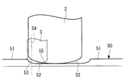
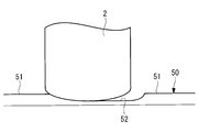
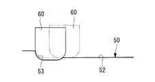
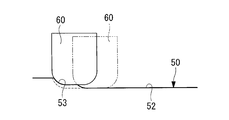
- the end mill 60 performs cutting at a position displaced in the axial direction, so that the end mill 60 causes the fillet-shaped portion with respect to the work 50 to have a surface-shaped portion. Also cut deep or shallow. As a result, the shape may have a step.
- the fillet-shaped portion 53 is formed deeper than the surface-shaped portion 52 as shown in FIG. 10, it is called shaving, and the fillet-shaped portion 53 is formed shallower than the surface-shaped portion 52 as shown in FIG. If left untouched, it is called uncut.
- the fatigue strength of the formed structural parts may decrease. Therefore, whether or not the fillet-shaped portion is within the reference shape is provided with specified values for the depth or height of the stepped portion, the position of the stepped portion from the rib, etc. for the formed structural component. The inspection is done. If it is out of the standard shape, additional work such as sanding is required to correct the shape.
- the present disclosure has been made in view of such circumstances, and in a shape portion formed by cutting, a shape that induces a decrease in fatigue strength can be generated without forming a step portion. It is an object of the present invention to provide a non-parts manufacturing method, a processing device, and a part.
- a part manufacturing method uses a processing apparatus including a bottom blade formed in a curved convex shape and an end mill having a radius blade formed in an arc shape provided at a corner.
- the shape to be processed with respect to the object to be processed has a surface-shaped portion and a fillet-shaped portion adjacent to the surface-shaped portion.
- the fillet-shaped portion is formed by forming only the surface-shaped portion so that there is an unprocessed portion, the fillet-shaped portion is formed in one pass by the radius blades provided in the corners and formed in the arc shape. Accordingly, the step portion is not formed in the fillet-shaped portion and the surface-shaped portion formed by cutting, and the fillet-shaped portion and the surface-shaped portion can be formed into an ideal shape that is the same as or close to the processing target.
- only the surface-shaped portion when only the surface-shaped portion is formed, only the surface-shaped portion may be formed so that there is an unprocessed portion at the boundary between the fillet-shaped portion and the surface-shaped portion.
- the unmachined portion in the height direction at the boundary between the fillet-shaped portion and the surface-shaped portion when forming only the surface-shaped portion is at the boundary when forming the fillet-shaped portion. It may be set so as to be larger than the unmachined portion in the height direction by the radius blade.
- the newly formed surface-shaped portion is a portion that intersects with the surface-shaped portion formed in the immediately preceding pass, and is formed in the height direction.
- a protruding ridge line portion may be formed.
- a processing apparatus includes a bottom blade formed in a convex shape on a curved surface, an end mill having a radius blade formed in an arc shape provided at a corner, and a drive unit for driving the end mill.
- a control unit that controls the drive unit, wherein the control unit is adjacent to the fillet-shaped portion with respect to the object to be processed so that the fillet-shaped portion of the target shape is left unprocessed.
- a component according to a third aspect of the present disclosure is a component having a surface-shaped portion and a fillet-shaped portion adjacent to the surface-shaped portion and having a curvature different from that of the surface-shaped portion, the fillet-shaped portion and the surface-shaped portion
- a convex portion is formed in the height direction on the surface shape portion side from the boundary portion of the portion, and on the fillet shape portion side from the convex portion, the surface shape portion and the fillet shape portion are flat surfaces. There is only a smooth curved surface.
- a step portion is not formed in a shape portion formed by cutting, and a shape that induces a decrease in fatigue strength is not generated.
- FIG. 3 is a vertical cross-sectional view showing a work formed by a processing device according to an embodiment of the present disclosure. It is a schematic diagram showing an end mill of a processing device concerning one embodiment of this indication.
- FIG. 3 is a vertical cross-sectional view showing an end mill and a work of a processing apparatus according to an embodiment of the present disclosure.
- FIG. 6 is an enlarged cross-sectional view showing the vicinity of a boundary portion of a work formed by the processing device according to the embodiment of the present disclosure.
- FIG. 6 is an enlarged cross-sectional view showing the vicinity of a ridgeline portion of a work formed by the processing apparatus according to the embodiment of the present disclosure.
- FIG. 3 is a vertical cross-sectional view showing a work formed by a processing device according to an embodiment of the present disclosure. It is a schematic diagram showing an end mill of a processing device concerning one embodiment of this indication.
- FIG. 3 is a vertical cross-sectional view showing an end mill and a work of a processing apparatus according
- FIG. 3 is an enlarged cross-sectional view showing the vicinity of a ridge line portion of a work formed by the processing device according to the embodiment of the present disclosure, and showing a state in which the end mill is axially displaced.
- FIG. 3 is a vertical cross-sectional view showing an end mill and a work of a processing apparatus according to an embodiment of the present disclosure.
- FIG. 3 is a vertical cross-sectional view showing an end mill and a work of a processing apparatus according to an embodiment of the present disclosure. It is a longitudinal cross-sectional view showing an end mill and a work of a conventional processing apparatus. It is a longitudinal cross-sectional view showing an end mill and a work of a conventional processing apparatus.
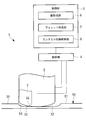
- the processing apparatus 1 includes, for example, end mills 2 and 3, a drive unit 4, and a control unit 5, as illustrated in FIG. 1.
- the processing apparatus 1 cuts the work 50 by the end mills 2 and 3 to form a predetermined shape on the work 50.
- the predetermined shape in the present embodiment is, in particular, a concave shape formed in the depth direction with respect to the work 50.
- the work 50 is a metal material such as an aluminum alloy or a titanium alloy.
- the work 50 is a plate-shaped member, and in order to secure the strength of the work 50, a rib 51 protruding in the height direction (thickness direction) is formed on one surface side.
- the region surrounded by the ribs 51 is formed thin.
- the area other than the uppermost surface of the rib 51 has a concave shape.
- the concave shape has a surface-shaped portion 52 formed on the bottom of the concave portion.
- a fillet-shaped portion 53 is provided at the connection portion between the surface-shaped portion 52 and the rib 51, instead of having a rounded pin angle.
- the surface shape portion 52 may be a flat surface having no curvature or a curved surface shape having a curvature.
- the fillet-shaped portion 53 has an arc shape having a predetermined radius. One end side of the fillet-shaped portion 53 is continuously formed with the surface-shaped portion 52, and the other end side of the fillet-shaped portion 53 constitutes a side wall surface of the rib 51 or is continuous with the side wall surface of the rib 51. Formed.
- the boundary portion 54 between the surface-shaped portion 52 and the fillet-shaped portion 53 is a portion where the curvature of the surface-shaped portion 52 (including a case where the curvature is 0 (zero)) and the curvature of the fillet-shaped portion 53 change. Is.
- the end mills 2 and 3 can cut the workpiece 50 by moving in the feed direction and the in-plane direction while rotating around the axis.
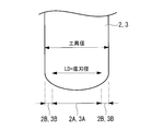
- the end mills 2 and 3 have bottom blades 2A and 3A formed in a curved convex shape and radius blades 2B and 3B formed in a corner portion and formed in an arc shape.
- the bottom blades 2A and 3A protrude so that the axial portions of the end mills 2 and 3 are located at the lowest position, and are formed in an arc shape having a predetermined radius (radius).
- the radius blades 2B and 3B are provided at the outer peripheral corners of the bottom blades 2A and 3A, and are formed in an arc shape having a predetermined radius (radius).
- the radius of the circular arc portion of the radius blades 2B and 3B be equal to or close to the radius of the fillet-shaped portion 53 that is the processing target.
- the radii of the circular arc portions of the bottom blades 2A and 3A are larger than the radii of the circular arc portions of the radius blades 2B and 3B.
- the radius of the circular arc portion of the bottom blades 2A and 3A is larger than the tool diameter (outer diameter) of the end mills 2 and 3, and is larger than the radius of the circular arc portion of the so-called ball end mill.
- the drive unit 4 includes a plurality of motors and a switching unit configured to switch between the end mills 2 and 3.
- the spindle motor is driven by receiving electric power to rotate the end mill 2 around the axis.
- the moving motor receives electric power and drives it to move the end mill 2 in the axial direction (feed direction) or in the direction perpendicular to the axial direction (in-plane direction).
- the switching unit switches between the end mills 2 and 3 under the control of the end mill switching control unit 8 and sets the end mill 2 or the end mill 3 for cutting to the work 50.
- the control unit 5 includes, for example, a surface forming unit 6, a fillet forming unit 7, an end mill switching control unit 8 and the like.
- the surface forming unit 6 controls the drive unit 4 so that the bottom blade 2A forms the surface-shaped portion 52 of the target shape for the workpiece 50. Further, as shown in FIG. 4 and FIG. 5, the surface forming part 6 has only the surface-shaped portion 52 for the work 50 so that the fillet-shaped portion 53 of the shape to be processed remains unprocessed.
- the drive unit 4 is controlled so as to form. Specifically, when forming the surface-shaped portion 52, the surface forming portion 6 forms only the surface-shaped portion 52 so that there is an unprocessed portion at the boundary portion 54 between the fillet-shaped portion 53 and the surface-shaped portion 52.
- the drive unit 4 is controlled.
- the fillet forming unit 7 controls the drive unit 4 to form the fillet-shaped portion 53 with respect to the work 50 by one pass by the radius blade 3B.
- the surface forming portion 6 is a portion where the newly formed surface-shaped portion 52 intersects with the surface-shaped portion 52 formed in the immediately preceding pass.
- the drive unit 4 is controlled so that the ridge line portion 55 protruding in the height direction as shown in FIG. 6 is formed.
- the shape targeted for processing the work 50 is a concave shape, and the concave shape has a surface-shaped portion 52 and a fillet-shaped portion 53 adjacent to the surface-shaped portion 52.
- the fillet-shaped part 53 is formed once by the radius blade 3B provided at the corner and formed in an arc shape. Formed by a path.
- the surface-shaped portion 52 is also formed by the bottom blade 3A. Therefore, the boundary between the surface-shaped portion 52 and the fillet-shaped portion 53 is formed by the bottom blade 3A and the radius blade 3B with a smooth curved surface without causing a step portion.
- the fillet-shaped portion 53 with high accuracy can be formed by one pass. Further, when the fillet-shaped portion 53 is formed by one pass, the newly formed surface-shaped portion 52 projects in the height direction at the portion where it intersects with the surface-shaped portion 52 formed in the immediately preceding pass. Ridge portion 55 is formed.
- the radius of the formed fillet-shaped portion 53 is formed with a predetermined radius, so that it is formed.
- the fillet-shaped portion 53 fits in the reference shape.
- the bottom blades 2A and 3A have a radius of curvature, but since they are larger than the tool diameter (outer diameter) of the end mills 2 and 3, the radius of curvature of the curved surface formed in the surface shape portion 52 is a bull nose end mill or a ball. Greater than the radius of curvature formed by the end mill. Therefore, the formed surface-shaped portion 52 fits in the reference shape.
- the bottom blade 3A has a large radius of curvature, as shown in FIG. 7, when an error occurs in the position of the end mill 3, the bottom blade 3A is formed in comparison with the amount of displacement of the end mill 3 in the height direction.
- the amount of positional displacement of the ridgeline portion 55 in the horizontal direction is large, but the amount of positional displacement of the formed ridgeline portion 55 in the height direction is small. Therefore, the formed surface-shaped portion 52 also easily fits in the reference shape.
- the control unit 5 is composed of, for example, a CPU (Central Processing Unit), a RAM (Random Access Memory), a ROM (Read Only Memory), and a computer-readable storage medium.
- a series of processes for realizing various functions are stored in a storage medium or the like in the form of a program as an example, and the CPU reads the program into a RAM or the like to execute information processing / arithmetic processing.
- the program is installed in a ROM or other storage medium in advance, provided in a state of being stored in a computer-readable storage medium, or delivered via wired or wireless communication means. Etc. may be applied.
- the computer-readable storage medium is a magnetic disk, a magneto-optical disk, a CD-ROM, a DVD-ROM, a semiconductor memory, or the like.
- the unprocessed amount of the boundary portion 54 between the fillet-shaped portion 53 and the surface-shaped portion 52 when the surface-shaped portion 52 is formed is t_surface, and the boundary portion between the fillet-shaped portion 53 and the surface-shaped portion 52 when the fillet-shaped portion 53 is formed
- the end mill 2 is selected so as to satisfy the following condition (equation (1)).
- the unprocessed amount t is expressed by the following equation (2).
- LR is a radius of the arc-shaped portion of the bottom blades 2A and 3A
- LD is a diameter of a region occupied by the bottom blades 2A and 3A in the end mill 2 in a direction perpendicular to the axial direction of the end mill 2.
- the unprocessed portion of the boundary portion 54 between the fillet-shaped portion 53 and the surface-shaped portion 52 is adjusted by adjusting the axial or radial offset of the end mill 2.
- the surface-shaped portion 52 is formed by adjusting the axial position of the end mill 2 so that the left side of the following formula (3) becomes larger.
- ⁇ is a displacement amount of the end mill 2 in the axial direction.
- the unmachined amount t Is close to 0 (zero).
- the radius of curvature of the surface-shaped portion 52 that is the processing target is large and is close to the planar shape, the processing residue occurs.
- the fact that the unprocessed amount is generated is utilized to perform the processing so that the step portion does not occur in the surface-shaped portion 52 and the fillet-shaped portion 53. It can be carried out.
- the work 50 is installed on the fixing jig, and the processing apparatus 1 moves to the work 50 installed on the fixing jig.
- the end mills 2 and 3 are driven at a predetermined rotation speed and moving speed with respect to the work 50.
- the work 50 has a predetermined shape, that is, a concave shape formed in the depth direction with respect to the work 50.
- the surface-shaped portion 52 corresponding to the bottom of the concave portion is formed on the work 50 using the bottom blade 2A of the end mill 2.
- the fillet-shaped portion 53 is not formed on the work 50, and only the surface-shaped portion 52 is formed so that the fillet-shaped portion 53 of the shape to be processed remains unprocessed.
- only the surface-shaped portion 52 is formed so that there is a processing residue.
- the fillet-shaped portion 53 is formed on the work 50 in only one pass.
- the radius of the arc portion of the radius blade 3B matches the radius of the fillet-shaped portion 53 to be processed, the fillet-shaped portion 53 with high accuracy can be formed by one pass.
- the newly-formed surface-shaped portion 52 is the surface-shaped portion 52 formed in the immediately preceding pass.
- the surface-shaped portion 52 is formed so that a ridgeline portion 55 protruding in the height direction is formed at a portion intersecting with. Therefore, the ridge line portion 55 is formed at the portion where the newly formed surface-shaped portion 52 intersects with the surface-shaped portion 52 formed in the immediately preceding pass.
- the ridge line portion 55 is formed closer to the surface-shaped portion 52 than the boundary portion 54 between the fillet-shaped portion 53 and the surface-shaped portion 52. That is, the ridgeline portion 55 is formed in the surface-shaped portion 52 of the concave shape of the formed component.
- the fillet-shaped portion 53 is formed by the radius blade 3B and the surface-shaped portion 52 is formed by the bottom blade 3A in the pass for forming the fillet-shaped portion 53, the fillet-shaped portion 53 side rather than the ridgeline portion 55 is formed.
- the surface-shaped portion 52 and the fillet-shaped portion 53 are only smooth curved surfaces without a flat surface. Therefore, when the fillet-shaped portion 53 is formed by one pass, the boundary between the surface-shaped portion 52 and the fillet-shaped portion 53 is smoothly curved by the bottom blade 3A and the radius blade 3B without causing a step. Is formed by.
- the step portion (cutting or uncut portion) is not formed in the fillet-shaped portion 53 and the surface-shaped portion 52 formed by cutting. Further, even if the end mill 2 is displaced in the height direction when forming the fillet-shaped portion 53, the displacement of the ridgeline portion 55 in the height direction is small. Therefore, the fillet-shaped portion 53 and the surface-shaped portion 52 can be formed into an ideal shape that is the same as or close to the processing target. As a result, the fatigue strength of the formed structural component does not decrease. Further, since the parts formed by the present embodiment are hard to come off from the reference shape, the work such as correcting the shape by performing additional work such as sanding may be reduced or unnecessary. ..
- Processing device 2 End mill 2 A: Bottom blade 2 B: Radius blade 3: End mill 3 A: Bottom blade 3 B: Radius blade 4: Drive section 5: Control section 6: Face forming section 7: Fillet forming section 8: End mill switching control section 50: Work piece 51: Rib 52: Surface-shaped portion 53: Fillet-shaped portion 54: Boundary portion 55: Ridge portion 60: End mill
Landscapes
- Engineering & Computer Science (AREA)
- Mechanical Engineering (AREA)
- Milling Processes (AREA)
Abstract
切削加工によって形成された形状部分において、段差部が形成されることなく、疲労強度の低下を誘発する形状を生じさせることがないことを目的とする。加工装置(1)は、曲面凸形状に形成された底刃と、隅部に設けられて円弧形状に形成されたラジアス刃を有するエンドミル(2,3)と、エンドミル(2,3)を駆動する駆動部(4)と、駆動部(4)を制御する制御部(5)とを備え、制御部(5)は、加工目標とする形状のうちフィレット形状部分に対して加工残しがあるように、被加工対象に対してフィレット形状部分に隣接する面形状部分のみを形成するように駆動部(4)を制御する面形成部(6)と、ラジアス刃によって被加工対象に対してフィレット形状部分を1回のパスで形成するように駆動部(4)を制御するフィレット形成部(7)とを備える。
Description
本開示は、部品製造方法、加工装置及び部品に関するものである。
胴体又は主翼のスキンなどの板状の航空機構造用部品では、軽量化のため部分的に板厚方向に薄肉にした形状が設けられる。板状部材は、強度を確保するため、板状部材の一面側にリブが形成され、リブ以外の領域が薄肉に形成される。面形状部分とリブ形状部分の接続部には、強度向上のため、丸みのないピン角とするのではなく、フィレットを設ける。
特許文献1には、溶接に関する技術分野において、フィレットにより連結される部材とみなすことができる形状について開示されている。
従来、フィレット形状部分を形成するためには、ブルノーズエンドミルやボールエンドミルといった切削工具を用いた切削加工によることが一般的である。しかし、これらの切削工具は、機械の繰り返し運転による精度低下、温度変化、振動又はワークの歪みなどの要因によって、切削加工によって所定の形状を得ることができず、形成された部品に誤差が生じる場合がある。
例えば、上述した要因によって、図10及び図11に示すように、エンドミル60が軸方向にずれた位置で切削を行うことによって、エンドミル60は、ワーク50に対してフィレット形状部分を面形状部分よりも深く又は浅く切削する。これにより、段差部が生じた形状となる場合がある。図10に示すように、フィレット形状部分53が面形状部分52よりも深く形成された場合、削り込みと呼ばれ、図11に示すように、フィレット形状部分53が面形状部分52よりも浅く形成された場合、削り残しと呼ばれる。
その結果、形成された構造用部品は、疲労強度が低下するおそれがある。そこで、形成された構造部品に対して、段差部の深さ又は高さ、段差部のリブからの位置などに規定値が設けられて、フィレット形状部分が基準の形状に収まっているか否かの検査が行われる。基準の形状から外れている場合は、やすり(サンディング)加工などの追加作業を行って、形状を修正するなどの作業が必要になる。
本開示は、このような事情に鑑みてなされたものであって、切削加工によって形成された形状部分において、段差部が形成されることなく、疲労強度の低下を誘発する形状を生じさせることがない部品製造方法、加工装置及び部品を提供することを目的とする。
本開示の第1態様に係る部品製造方法は、曲面凸形状に形成された底刃と、隅部に設けられて円弧形状に形成されたラジアス刃を有するエンドミルを備える加工装置を用いた部品製造方法であって、加工目標とする形状のうちフィレット形状部分に対して加工残しがあるように、被加工対象に対して前記フィレット形状部分に隣接する面形状部分のみを形成するステップと、前記ラジアス刃によって前記被加工対象に対して前記フィレット形状部分を1回のパスで形成するステップとを備える。
この構成によれば、被加工対象に対して加工目標とする形状は、面形状部分と、面形状部分に隣接するフィレット形状部分を有し、面形状部分を形成するとき、フィレット形状部分に対して加工残しがあるように面形状部分のみを形成し、フィレット形状部分を形成するとき、隅部に設けられて円弧形状に形成されたラジアス刃によってフィレット形状部分を1回のパスで形成する。
これにより、切削加工によって形成されたフィレット形状部分と面形状部分において、段差部が形成されず、フィレット形状部分及び面形状部分を、加工目標と同一又は近い理想的な形状に形成できる。
これにより、切削加工によって形成されたフィレット形状部分と面形状部分において、段差部が形成されず、フィレット形状部分及び面形状部分を、加工目標と同一又は近い理想的な形状に形成できる。
上記第1態様において、前記面形状部分のみを形成するとき、前記フィレット形状部分と前記面形状部分の境界部において、加工残しがあるように前記面形状部分のみを形成してもよい。
上記第1態様において、前記面形状部分のみを形成するときの前記フィレット形状部分と前記面形状部分の境界部における高さ方向の加工残しは、前記フィレット形状部分を形成するときの前記境界部における、前記ラジアス刃による高さ方向の加工残しよりも大きくなるように設定されてもよい。
上記第1態様において、1回のパスによって前記フィレット形状部分が形成されるとき、新たに形成された面形状部分が、直前のパスで形成された面形状部分と交わる部分で、高さ方向に突出した稜線部が形成されてもよい。
本開示の第2態様に係る加工装置は、曲面凸形状に形成された底刃と、隅部に設けられて円弧形状に形成されたラジアス刃を有するエンドミルと、前記エンドミルを駆動する駆動部と、前記駆動部を制御する制御部とを備え、前記制御部は、加工目標とする形状のうちフィレット形状部分に対して加工残しがあるように、被加工対象に対して前記フィレット形状部分に隣接する面形状部分のみを形成するように前記駆動部を制御する面形成部と、前記ラジアス刃によって前記被加工対象に対して前記フィレット形状部分を1回のパスで形成するように前記駆動部を制御するフィレット形成部とを備える。
本開示の第3態様に係る部品は、面形状部分と、前記面形状部分に隣接し前記面形状部分と曲率の異なるフィレット形状部分とを有する部品であって、前記フィレット形状部分と前記面形状部分の境界部よりも前記面形状部分側において高さ方向に凸状部が形成されており、前記凸状部よりも前記フィレット形状部分側において、前記面形状部分と前記フィレット形状部分は、平面のない滑らかな曲面のみである。
本開示によれば、切削加工によって形成された形状部分において、段差部が形成されることなく、疲労強度の低下を誘発する形状を生じさせることがない。
以下に、本開示に係る実施形態について、図面を参照して説明する。
本開示の一実施形態に係る加工装置1は、図1に示すように、例えば、エンドミル2,3と、駆動部4と、制御部5を備える。加工装置1は、エンドミル2,3によって、ワーク50を切削して、ワーク50に所定の形状を形成する。本実施形態における所定の形状は、特に、ワーク50に対して深さ方向に形成された凹状形状である。ワーク50は、例えばアルミニウム合金、チタン合金などの金属材料である。
本開示の一実施形態に係る加工装置1は、図1に示すように、例えば、エンドミル2,3と、駆動部4と、制御部5を備える。加工装置1は、エンドミル2,3によって、ワーク50を切削して、ワーク50に所定の形状を形成する。本実施形態における所定の形状は、特に、ワーク50に対して深さ方向に形成された凹状形状である。ワーク50は、例えばアルミニウム合金、チタン合金などの金属材料である。
図1及び図2に示すように、例えば、ワーク50は、板状部材であり、ワーク50の強度を確保するため、一面側において高さ方向(厚さ方向)に突出したリブ51が形成され、リブ51に囲まれた領域が薄肉に形成される。この場合、リブ51の最上面以外の領域が、凹状形状を有する。凹状形状は、凹状部分の底部に形成された面形状部分52を有する。そして、面形状部分52とリブ51の接続部には、強度向上のため、丸みのないピン角とするのではなく、フィレット形状部分53が設けられる。
面形状部分52は、曲率のない平面でもよいし、曲率を有する曲面形状でもよい。フィレット形状部分53は、所定の半径を有する円弧形状である。フィレット形状部分53のうち一端側は、面形状部分52と連続的に形成され、フィレット形状部分53のうち他端側は、リブ51の側壁面を構成する、又は、リブ51の側壁面と連続的に形成される。
面形状部分52とフィレット形状部分53の境界部54は、面形状部分52の曲率(曲率が0(ゼロ)である平面の場合を含む。)と、フィレット形状部分53の曲率とが変化する部分である。
エンドミル2,3は、軸線周りに回転しながら、送り方向や面内方向に移動することによって、ワーク50を切削できる。
エンドミル2,3は、図3に示すように、曲面凸形状に形成された底刃2A,3Aと、隅部に設けられて円弧形状に形成されたラジアス刃2B,3Bを有する。
底刃2A,3Aは、エンドミル2,3の軸線上部分が最も下方に位置するように突出しており、所定の半径(ラジアス)を有する円弧形状に形成されている。ラジアス刃2B,3Bは、底刃2A,3Aの外周側隅部に設けられ、所定の半径(ラジアス)を有する円弧形状に形成されている。ラジアス刃2B,3Bの円弧部分の半径は、加工目標とするフィレット形状部分53の半径と一致又は近いことが望ましい。底刃2A,3Aの円弧部分の半径は、ラジアス刃2B,3Bの円弧部分の半径よりも大きい。底刃2A,3Aの円弧部分の半径は、エンドミル2,3の工具径(外径)よりも大きく、いわゆるボールエンドミルの円弧部分の半径よりも大きい。
エンドミル2,3は、図3に示すように、曲面凸形状に形成された底刃2A,3Aと、隅部に設けられて円弧形状に形成されたラジアス刃2B,3Bを有する。
底刃2A,3Aは、エンドミル2,3の軸線上部分が最も下方に位置するように突出しており、所定の半径(ラジアス)を有する円弧形状に形成されている。ラジアス刃2B,3Bは、底刃2A,3Aの外周側隅部に設けられ、所定の半径(ラジアス)を有する円弧形状に形成されている。ラジアス刃2B,3Bの円弧部分の半径は、加工目標とするフィレット形状部分53の半径と一致又は近いことが望ましい。底刃2A,3Aの円弧部分の半径は、ラジアス刃2B,3Bの円弧部分の半径よりも大きい。底刃2A,3Aの円弧部分の半径は、エンドミル2,3の工具径(外径)よりも大きく、いわゆるボールエンドミルの円弧部分の半径よりも大きい。
駆動部4は、複数のモータや、エンドミル2,3を切り換える構成を有する切換部などを備える。主軸モータは、電力を受けて駆動し、エンドミル2を軸線周りに回転させる。移動用モータは、電力を受けて駆動し、エンドミル2を軸線方向(送り方向)又は軸線方向に対して垂直方向(面内方向)に移動させる。切換部は、エンドミル切換制御部8による制御によって、エンドミル2,3を切り換えて、切削加工を行うほうのエンドミル2又はエンドミル3をワーク50に対してセットする。
制御部5は、例えば、面形成部6と、フィレット形成部7と、エンドミル切換制御部8などを有する。
面形成部6は、底刃2Aによってワーク50に対して加工目標とする形状のうち面形状部分52を形成するように駆動部4を制御する。
また、面形成部6は、図4及び図5に示すように、加工目標とする形状のうちフィレット形状部分53に対して加工残しがあるように、ワーク50に対して面形状部分52のみを形成するように駆動部4を制御する。具体的には、面形成部6は、面形状部分52を形成するとき、フィレット形状部分53と面形状部分52の境界部54において、加工残しがあるように面形状部分52のみを形成するように駆動部4を制御する。
また、面形成部6は、図4及び図5に示すように、加工目標とする形状のうちフィレット形状部分53に対して加工残しがあるように、ワーク50に対して面形状部分52のみを形成するように駆動部4を制御する。具体的には、面形成部6は、面形状部分52を形成するとき、フィレット形状部分53と面形状部分52の境界部54において、加工残しがあるように面形状部分52のみを形成するように駆動部4を制御する。
フィレット形状部分53を形成する前の面形状部分52のみを形成するときのフィレット形状部分53と面形状部分52の境界部54における、底刃2A又はラジアス刃2Bによる高さ方向の加工残し量t_surfaceは、フィレット形状部分53を形成するときのフィレット形状部分53と面形状部分52の境界部54における、ラジアス刃3Bによる高さ方向の加工残し量t_filletよりも大きくなるように設定されている。
フィレット形成部7は、ラジアス刃3Bによってワーク50に対してフィレット形状部分53を1回のパスで形成するように駆動部4を制御する。面形成部6は、1回のパスによってフィレット形状部分53が形成されるとき、新たに形成された面形状部分52が、直前のパスで形成された面形状部分52と交わる部分で、図2及び図6に示すような高さ方向に突出した稜線部55が形成されるように駆動部4を制御する。
ワーク50に対して加工目標とする形状は、凹状形状であり、凹状形状は、面形状部分52と、面形状部分52に隣接するフィレット形状部分53を有する。面形成部6によって駆動部4が制御されることにより、面形状部分52のみを形成するとき、フィレット形状部分53に対して加工残しがあるように面形状部分52のみが形成される。
また、フィレット形成部7によって駆動部4が制御されることにより、フィレット形状部分53を形成するとき、隅部に設けられて円弧形状に形成されたラジアス刃3Bによってフィレット形状部分53が1回のパスで形成される。このとき、底刃3Aによって面形状部分52も形成される。したがって、底刃3Aとラジアス刃3Bによって、面形状部分52とフィレット形状部分53の境界が、段差部を生じさせることなく、滑らかな曲面で形成される。
ラジアス刃3Bの円弧部分の半径が、加工目標とするフィレット形状部分53の半径と一致しているとき、1回のパスによって、精度の良いフィレット形状部分53を形成できる。また、1回のパスによってフィレット形状部分53が形成されるとき、新たに形成された面形状部分52が、直前のパスで形成された面形状部分52と交わる部分で、高さ方向に突出した稜線部55が形成される。
フィレット形状部分53を1回のパスで形成するとき、エンドミル3の位置に誤差が生じた場合でも、形成されるフィレット形状部分53の半径は、所定の半径で形成されているため、形成されるフィレット形状部分53は、基準の形状に収まる。
また、底刃2A,3Aは、曲率半径を有するが、エンドミル2,3の工具径(外径)よりも大きいため、面形状部分52に形成される曲面の曲率半径は、ブルノーズエンドミルやボールエンドミルによって形成される曲率半径よりも大きい。そのため、形成される面形状部分52は、基準の形状に収まる。
さらに、底刃3Aは、曲率半径が大きいことから、図7に示すように、エンドミル3の位置に誤差が生じた場合、エンドミル3の高さ方向の位置のずれ量に比べて、形成される稜線部55の水平方向の位置のずれ量は大きいが、形成される稜線部55の高さ方向の位置ずれ量は小さい。したがって、形成される面形状部分52についても、基準の形状に収まりやすい。
制御部5は、例えば、CPU(Central Processing Unit)、RAM(Random Access Memory)、ROM(Read Only Memory)、及びコンピュータ読み取り可能な記憶媒体等から構成されている。そして、各種機能を実現するための一連の処理は、一例として、プログラムの形式で記憶媒体等に記憶されており、このプログラムをCPUがRAM等に読み出して、情報の加工・演算処理を実行することにより、各種機能が実現される。なお、プログラムは、ROMやその他の記憶媒体に予めインストールしておく形態や、コンピュータ読み取り可能な記憶媒体に記憶された状態で提供される形態、有線又は無線による通信手段を介して配信される形態等が適用されてもよい。コンピュータ読み取り可能な記憶媒体とは、磁気ディスク、光磁気ディスク、CD-ROM、DVD-ROM、半導体メモリ等である。
面形状部分52を形成するときのフィレット形状部分53と面形状部分52の境界部54の加工残し量をt_surface、フィレット形状部分53を形成するときのフィレット形状部分53と面形状部分52の境界部54の加工残し量をt_filletとすると、以下の条件(式(1))を満たすように、エンドミル2を選定する。
t_surface>t_fillet ・・・(1)
t_surface>t_fillet ・・・(1)
ここで、加工残し量tは、下記の式(2)で表される。なお、LRは、底刃2A,3Aの円弧形状部分の半径であり、LDは、エンドミル2において底刃2A,3Aが占める領域に関する、エンドミル2の軸方向に対して垂直方向の直径である。

なお、エンドミル2の選定において、式(1)を満たさない場合でも、エンドミル2の軸方向又は径方向のオフセットで調整して、フィレット形状部分53と面形状部分52の境界部54の加工残しが発生するようにエンドミル2の位置を調整してもよい。例えば、下記の式(3)の左辺のほうが大きくなるように、エンドミル2の軸方向の位置を調整して面形状部分52を形成する。
t_surface+α>t_fillet ・・・(3)
ここで、αは、エンドミル2の軸方向のずれ量である。
t_surface+α>t_fillet ・・・(3)
ここで、αは、エンドミル2の軸方向のずれ量である。
エンドミル2を用いたワーク50の加工において、底刃2Aの円弧形状部分の曲率半径が、加工目標とする凹状形状の面形状部分52の曲率半径と同一又は近似している場合、加工残し量tは0(ゼロ)に近い。一方、加工目標とする面形状部分52の曲率半径が大きく、平面形状に近い場合、加工残しが発生する。本実施形態では、円弧形状部分を有する底刃2Aによる加工結果において、加工残し量が発生することを利用することによって、面形状部分52とフィレット形状部分53において段差部が生じないように加工を行うことができる。
次に、図2を参照して、本実施形態に係る加工装置1の動作について説明する。
ワーク50に所定の形状を形成するため、ワーク50と加工装置1を準備する。例えば、ワーク50を固定治具に設置し、加工装置1が、固定治具に設置されたワーク50へ移動する。
そして、ワーク50に対して所定の回転数及び移動速度でエンドミル2,3を駆動させる。本実施形態では、ワーク50に所定の形状、すなわち、ワーク50に対して深さ方向に形成された凹状形状を形成する。
まず、図8に示すように、エンドミル2の底刃2Aを用いて、ワーク50に対して、凹状部分の底部に相当する面形状部分52を形成する。このとき、加工目標とする形状のうちフィレット形状部分53に対して加工残しがあるように、ワーク50に対してフィレット形状部分53は形成せず、面形状部分52のみを形成する。具体的には、フィレット形状部分53と面形状部分52の境界部54において、加工残しがあるように面形状部分52のみを形成する。
次に、図9に示すように、エンドミル3のラジアス刃3Bを用いて、ワーク50に対して、フィレット形状部分53を1回のパスのみで形成する。ラジアス刃3Bの円弧部分の半径が、加工目標とするフィレット形状部分53の半径と一致しているとき、1回のパスによって、精度の良いフィレット形状部分53を形成できる。
なお、フィレット形状部分53を形成するときのパスで、底刃3Aによって面形状部分52が形成されるとき、新たに形成された面形状部分52が、直前のパスで形成された面形状部分52と交わる部分で、高さ方向に突出した稜線部55が形成されるように、面形状部分52が形成される。したがって、新たに形成された面形状部分52が、直前のパスで形成された面形状部分52と交わる部分で、稜線部55が形成される。これにより、稜線部55が、フィレット形状部分53と面形状部分52の境界部54よりも面形状部分52側に形成される。すなわち、形成された部品の凹状形状のうち、面形状部分52には稜線部55が形成されている。
フィレット形状部分53を形成するときのパスで、ラジアス刃3Bによってフィレット形状部分53が形成され、かつ、底刃3Aによって面形状部分52が形成されるため、稜線部55よりもフィレット形状部分53側において、面形状部分52と前記フィレット形状部分53は、平面のない滑らかな曲面のみである。したがって、1回のパスによってフィレット形状部分53が形成されるとき、底刃3Aとラジアス刃3Bによって、面形状部分52とフィレット形状部分53の境界が、段差部を生じさせることなく、滑らかな曲面で形成される。
以上、本実施形態によれば、切削加工によって形成されたフィレット形状部分53と面形状部分52において、段差部(削り込み又は削り残し)が形成されない。また、フィレット形状部分53を形成するときに、エンドミル2の高さ方向の位置ずれが生じた場合でも、稜線部55の高さ方向の位置ずれは小さい。よって、フィレット形状部分53及び面形状部分52を、加工目標と同一又は近い理想的な形状に形成できる。その結果、形成された構造用部品は、疲労強度が低下するおそれがない。さらに、本実施形態によって形成された部品は、基準の形状から外れにくいため、やすり(サンディング)加工などの追加作業を行って、形状を修正するなどの作業が低減されたり、不要になったりする。
1 :加工装置
2 :エンドミル
2A :底刃
2B :ラジアス刃
3 :エンドミル
3A :底刃
3B :ラジアス刃
4 :駆動部
5 :制御部
6 :面形成部
7 :フィレット形成部
8 :エンドミル切換制御部
50 :ワーク
51 :リブ
52 :面形状部分
53 :フィレット形状部分
54 :境界部
55 :稜線部
60 :エンドミル
2 :エンドミル
2A :底刃
2B :ラジアス刃
3 :エンドミル
3A :底刃
3B :ラジアス刃
4 :駆動部
5 :制御部
6 :面形成部
7 :フィレット形成部
8 :エンドミル切換制御部
50 :ワーク
51 :リブ
52 :面形状部分
53 :フィレット形状部分
54 :境界部
55 :稜線部
60 :エンドミル
Claims (6)
- 曲面凸形状に形成された底刃と、隅部に設けられて円弧形状に形成されたラジアス刃を有するエンドミルを備える加工装置を用いた部品製造方法であって、
加工目標とする形状のうちフィレット形状部分に対して加工残しがあるように、被加工対象に対して前記フィレット形状部分に隣接する面形状部分のみを形成するステップと、
前記ラジアス刃によって前記被加工対象に対して前記フィレット形状部分を1回のパスで形成するステップと、
を備える部品製造方法。 - 前記面形状部分のみを形成するとき、前記フィレット形状部分と前記面形状部分の境界部において、加工残しがあるように前記面形状部分のみを形成する請求項1に記載の部品製造方法。
- 前記面形状部分のみを形成するときの前記フィレット形状部分と前記面形状部分の境界部における高さ方向の加工残しは、前記フィレット形状部分を形成するときの前記境界部における、前記ラジアス刃による高さ方向の加工残しよりも大きくなるように設定されている請求項1に記載の部品製造方法。
- 1回のパスによって前記フィレット形状部分が形成されるとき、新たに形成された面形状部分が、直前のパスで形成された面形状部分と交わる部分で、高さ方向に突出した稜線部が形成される請求項1に記載の部品製造方法。
- 曲面凸形状に形成された底刃と、隅部に設けられて円弧形状に形成されたラジアス刃を有するエンドミルと、
前記エンドミルを駆動する駆動部と、
前記駆動部を制御する制御部と、
を備え、
前記制御部は、
被加工対象に対して加工目標とする形状のうちフィレット形状部分に対して加工残しがあるように、前記フィレット形状部分に隣接する面形状部分のみを形成するように前記駆動部を制御する面形成部と、
前記ラジアス刃によって前記被加工対象に対して前記フィレット形状部分を1回のパスで形成するように前記駆動部を制御するフィレット形成部と、
を備える加工装置。 - 面形状部分と、前記面形状部分に隣接し前記面形状部分と曲率の異なるフィレット形状部分とを有する部品であって、
前記フィレット形状部分と前記面形状部分の境界部よりも前記面形状部分側において高さ方向に凸状部が形成されており、
前記凸状部よりも前記フィレット形状部分側において、前記面形状部分と前記フィレット形状部分は、平面のない滑らかな曲面のみである部品。
Priority Applications (1)
| Application Number | Priority Date | Filing Date | Title |
|---|---|---|---|
| US17/268,759 US12427589B2 (en) | 2018-11-12 | 2019-10-21 | Method for manufacturing component, processing apparatus, and component |
Applications Claiming Priority (2)
| Application Number | Priority Date | Filing Date | Title |
|---|---|---|---|
| JP2018212149A JP7143186B2 (ja) | 2018-11-12 | 2018-11-12 | 部品製造方法、加工装置及び部品 |
| JP2018-212149 | 2018-11-12 |
Publications (1)
| Publication Number | Publication Date |
|---|---|
| WO2020100536A1 true WO2020100536A1 (ja) | 2020-05-22 |
Family
ID=70730925
Family Applications (1)
| Application Number | Title | Priority Date | Filing Date |
|---|---|---|---|
| PCT/JP2019/041383 Ceased WO2020100536A1 (ja) | 2018-11-12 | 2019-10-21 | 部品製造方法、加工装置及び部品 |
Country Status (3)
| Country | Link |
|---|---|
| US (1) | US12427589B2 (ja) |
| JP (1) | JP7143186B2 (ja) |
| WO (1) | WO2020100536A1 (ja) |
Cited By (1)
| Publication number | Priority date | Publication date | Assignee | Title |
|---|---|---|---|---|
| CN116532697A (zh) * | 2023-04-07 | 2023-08-04 | 成都飞机工业(集团)有限责任公司 | 一种复材蒙皮厚度自适应补偿加工方法 |
Families Citing this family (1)
| Publication number | Priority date | Publication date | Assignee | Title |
|---|---|---|---|---|
| JP7139266B2 (ja) * | 2019-02-22 | 2022-09-20 | 三菱重工業株式会社 | エンドミル |
Citations (5)
| Publication number | Priority date | Publication date | Assignee | Title |
|---|---|---|---|---|
| US4260304A (en) * | 1979-10-10 | 1981-04-07 | Dresser Industries, Inc. | Method for machining an impeller cover |
| JPS59143619U (ja) * | 1983-03-16 | 1984-09-26 | 株式会社神戸製鋼所 | コ−ナア−ル切削工具 |
| JPH09292906A (ja) * | 1996-04-26 | 1997-11-11 | Nissan Motor Co Ltd | 金型非成形部逃がし加工自動化用camシステム |
| US20050025584A1 (en) * | 2003-07-12 | 2005-02-03 | Werner Kolker | Face milling cutter |
| WO2015116398A1 (en) * | 2014-01-28 | 2015-08-06 | United Technologies Corporation | Compound fillet radii cutter |
Family Cites Families (14)
| Publication number | Priority date | Publication date | Assignee | Title |
|---|---|---|---|---|
| US5378091A (en) * | 1992-06-17 | 1995-01-03 | Makino Milling Machine Co., Ltd. | Method and apparatus for machining a workpiece |
| GB2306353B (en) | 1995-10-28 | 1998-10-07 | Rolls Royce Plc | A method of manufacturing a blade |
| US6779270B2 (en) | 1999-07-13 | 2004-08-24 | The Penn States Research Foundation | Full form roll finishing technique |
| JP2002059308A (ja) * | 2000-08-21 | 2002-02-26 | Tadashi Sugiyama | フライスカッター |
| KR100845873B1 (ko) * | 2003-12-17 | 2008-07-14 | 쇼와 덴코 가부시키가이샤 | 단조용 금형 제조 방법 |
| JP2006043858A (ja) * | 2004-08-09 | 2006-02-16 | Toyota Motor Corp | 切削加工方法 |
| DE102007010163A1 (de) * | 2007-02-28 | 2008-09-04 | Sandvik Intellectual Property Ab | Kugelkopffräser |
| JP5803647B2 (ja) * | 2011-02-16 | 2015-11-04 | 三菱日立ツール株式会社 | エンドミル |
| JP6265089B2 (ja) | 2014-09-05 | 2018-01-24 | Jfeスチール株式会社 | 自動車用足廻り部品の疲労強度向上方法 |
| JP6168077B2 (ja) | 2015-02-12 | 2017-07-26 | Jfeスチール株式会社 | プレス成形部品の接合構造、該接合構造を有する自動車用構造部品及び接合部品の製造方法 |
| DE102016117932B4 (de) * | 2016-09-22 | 2020-06-10 | Open Mind Technologies Ag | Verfahren zur materialabtragenden Bearbeitung von Verrundungsflächen eines Werkstückes |
| JP7114508B2 (ja) * | 2019-02-22 | 2022-08-08 | 三菱重工業株式会社 | エンドミルの製造方法及び切削加工方法 |
| JP7139266B2 (ja) * | 2019-02-22 | 2022-09-20 | 三菱重工業株式会社 | エンドミル |
| JP7481617B2 (ja) * | 2020-03-23 | 2024-05-13 | 株式会社Moldino | 加工方法および金型の製造方法 |
-
2018
- 2018-11-12 JP JP2018212149A patent/JP7143186B2/ja active Active
-
2019
- 2019-10-21 WO PCT/JP2019/041383 patent/WO2020100536A1/ja not_active Ceased
- 2019-10-21 US US17/268,759 patent/US12427589B2/en active Active
Patent Citations (5)
| Publication number | Priority date | Publication date | Assignee | Title |
|---|---|---|---|---|
| US4260304A (en) * | 1979-10-10 | 1981-04-07 | Dresser Industries, Inc. | Method for machining an impeller cover |
| JPS59143619U (ja) * | 1983-03-16 | 1984-09-26 | 株式会社神戸製鋼所 | コ−ナア−ル切削工具 |
| JPH09292906A (ja) * | 1996-04-26 | 1997-11-11 | Nissan Motor Co Ltd | 金型非成形部逃がし加工自動化用camシステム |
| US20050025584A1 (en) * | 2003-07-12 | 2005-02-03 | Werner Kolker | Face milling cutter |
| WO2015116398A1 (en) * | 2014-01-28 | 2015-08-06 | United Technologies Corporation | Compound fillet radii cutter |
Cited By (1)
| Publication number | Priority date | Publication date | Assignee | Title |
|---|---|---|---|---|
| CN116532697A (zh) * | 2023-04-07 | 2023-08-04 | 成都飞机工业(集团)有限责任公司 | 一种复材蒙皮厚度自适应补偿加工方法 |
Also Published As
| Publication number | Publication date |
|---|---|
| JP7143186B2 (ja) | 2022-09-28 |
| US20210323081A1 (en) | 2021-10-21 |
| US12427589B2 (en) | 2025-09-30 |
| JP2020078834A (ja) | 2020-05-28 |
Similar Documents
| Publication | Publication Date | Title |
|---|---|---|
| US20250153254A1 (en) | End mill and method of manufacturing end mill | |
| JP2008279547A (ja) | 溝加工方法および総形回転切削工具 | |
| US9101991B1 (en) | Method and apparatus for non-spindle multi-axis machining | |
| JP2017530016A (ja) | 歯部を加工する方法及び加工用工具並びに工作機械 | |
| WO2020100536A1 (ja) | 部品製造方法、加工装置及び部品 | |
| WO2015114734A1 (ja) | 切削加工方法および工具経路生成装置 | |
| JP2012086296A (ja) | 溝加工方法 | |
| JP6704204B2 (ja) | 切削加工方法 | |
| JP2014193522A (ja) | エンドミル及びその製造方法 | |
| JP7016568B1 (ja) | フレネルレンズ金型製造方法、加工装置および切削工具 | |
| US11642748B2 (en) | Machining program creation method, workpiece machining method, and machine tool control device | |
| CN105759717B (zh) | 一种用于五轴数控加工的刀具轨迹防过切的方法 | |
| JP7139266B2 (ja) | エンドミル | |
| JP2008279548A (ja) | 切削加工方法および総形回転切削工具 | |
| JP3676594B2 (ja) | スローアウェイチップならびに回転切削工具、および金型形成方法 | |
| JP5705355B1 (ja) | 壁部の加工方法および工具経路生成装置 | |
| JP7075584B2 (ja) | ラジアスエンドミル及びこれを用いた工作機械、並びにラジアスエンドミルの設計方法及び加工方法 | |
| JP2003170333A (ja) | 工具送り経路の作成方法 | |
| JP6371339B2 (ja) | 加工方法、加工装置および動力伝達部品の製造方法 | |
| CN115592478A (zh) | 基于活动标架的复杂曲线刃的螺旋槽磨削方法 | |
| JP2002172513A (ja) | 切削加工方法 | |
| JP5939091B2 (ja) | ラジアスエンドミル及びその製造方法 | |
| JPH10230407A (ja) | エンドミル | |
| JP2023023503A (ja) | 金型の加工方法 | |
| JP2024065805A (ja) | ロボット装置を用いた切削加工システム及び切削工具、切削加工方法 |
Legal Events
| Date | Code | Title | Description |
|---|---|---|---|
| 121 | Ep: the epo has been informed by wipo that ep was designated in this application |
Ref document number: 19883391 Country of ref document: EP Kind code of ref document: A1 |
|
| NENP | Non-entry into the national phase |
Ref country code: DE |
|
| 122 | Ep: pct application non-entry in european phase |
Ref document number: 19883391 Country of ref document: EP Kind code of ref document: A1 |
|
| WWG | Wipo information: grant in national office |
Ref document number: 17268759 Country of ref document: US |