WO2020096035A1 - Endoscope - Google Patents
Endoscope Download PDFInfo
- Publication number
- WO2020096035A1 WO2020096035A1 PCT/JP2019/043825 JP2019043825W WO2020096035A1 WO 2020096035 A1 WO2020096035 A1 WO 2020096035A1 JP 2019043825 W JP2019043825 W JP 2019043825W WO 2020096035 A1 WO2020096035 A1 WO 2020096035A1
- Authority
- WO
- WIPO (PCT)
- Prior art keywords
- hole
- endoscope
- tip
- tube
- endoscope according
- Prior art date
Links
Images


Classifications
-
- A—HUMAN NECESSITIES
- A61—MEDICAL OR VETERINARY SCIENCE; HYGIENE
- A61B—DIAGNOSIS; SURGERY; IDENTIFICATION
- A61B1/00—Instruments for performing medical examinations of the interior of cavities or tubes of the body by visual or photographical inspection, e.g. endoscopes; Illuminating arrangements therefor
- A61B1/005—Flexible endoscopes
-
- G—PHYSICS
- G02—OPTICS
- G02B—OPTICAL ELEMENTS, SYSTEMS OR APPARATUS
- G02B23/00—Telescopes, e.g. binoculars; Periscopes; Instruments for viewing the inside of hollow bodies; Viewfinders; Optical aiming or sighting devices
- G02B23/24—Instruments or systems for viewing the inside of hollow bodies, e.g. fibrescopes
Definitions
- the present invention relates to an endoscope.
- An endoscope is used in which a plurality of built-in objects such as a cable bundle, a light guide fiber, various tubes, and bending wires are inserted inside an insertion portion having a bending portion on the tip side of the flexible portion.
- the bending portion bends according to a user operation.
- An endoscope has been proposed in which a bending tube having a joint structure in which a plurality of bending pieces are combined protects a built-in object in the bending portion and covers the flexible portion and the bending portion with an integral outer tube (Patent Document 1). ).
- An endoscope has been proposed in which the insertion portion is configured by a multi-lumen tube and a plurality of cutouts are provided in a portion corresponding to the bending portion (Patent Document 2).
- the endoscope described in Patent Document 1 has an insertion part having a complicated structure, which is composed of many parts.
- the endoscope described in Patent Document 2 reduces the number of parts and simplifies the structure of the endoscope by using each lumen of the multi-lumen tube for an air supply / water supply conduit, a channel conduit, and the like. it can.
- it since it is difficult to provide an air / water supply conduit, a channel conduit, etc. at the position where the notch is formed, it is difficult to realize an endoscope having a practical thickness.
- One aspect is to provide an endoscope with a small number of parts.
- the endoscope includes an operation section and an insertion section having one end connected to the operation section, and the insertion section includes a tip section arranged at a tip of the insertion section, the tip section and the operation section.
- a multi-lumen tube having a plurality of through holes including a curved wire hole provided in the longitudinal direction, and a plurality of through holes penetrating the curved wire hole, the first end is fixed to the distal end portion, and the second end is A curved wire connected to a pulling mechanism provided in the operation portion and a portion between the end portion on the tip end side of the multi-lumen tube and a predetermined distance away from the end portion on the operation portion side that are continuous.
- the rigidity imparting portion provided in the same manner, and the operation portion side is thicker than the tip end portion side.
- FIG. 3 is a partial cross-sectional view of the endoscope taken along the line III-III in FIG. 2. It is a front view of a flexible tube. It is a side view of a flexible tube. 6 is a cross-sectional view of the flexible tube taken along the line VI-VI in FIG. 5. It is an expanded sectional view of the A section in FIG. It is explanatory drawing explaining the flexibility of a flexible tube. It is a graph explaining the dimension of a flexible tube. It is explanatory drawing explaining the curved shape of an insertion part. It is a side view of the flexible tube of Embodiment 2.
- FIG. 18 is a cross-sectional view of the flexible tube taken along line XVIII-XVIII in FIG. 17. It is a front view of the flexible tube of Embodiment 9. It is an enlarged view of the B section in FIG. It is a partially expanded view of the modification of the flexible tube of Embodiment 9.
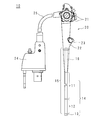
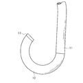
- FIG. 1 is an external view of the endoscope 10.
- the endoscope 10 of the present embodiment is a flexible endoscope for the digestive tract.
- the endoscope 10 has an insertion section 14, an operation section 20, a universal cord 25, and a connector section 24.
- the operation unit 20 has a bending knob 21 and a channel inlet 22.
- a forceps plug 23 having an insertion opening for inserting a treatment tool or the like is fixed to the channel entrance 22.
- the insertion portion 14 is long, and one end of the insertion portion 14 is connected to the operation portion 20 via the folding portion 16.
- the insertion portion 14 has a flexible portion 11, a bending portion 12, and a tip portion 13 in this order from the operation portion 20 side.
- the bending portion 12 bends according to the operation of the bending knob 21.
- the longitudinal direction of the insertion part 14 will be referred to as the insertion direction.
- the side closer to the operation unit 20 along the insertion direction is referred to as the operation unit side, and the side farther from the operation unit 20 is referred to as the distal end side.
- the universal cord 25 is long and has a first end connected to the operation unit 20 and a second end connected to the connector unit 24.
- the universal cord 25 is flexible.
- the connector section 24 is connected to an endoscope processor, a light source device, a display device, an air / water supply device, and the like, which are not shown.
- FIG. 2 is an external view of the end surface of the tip portion 13.
- An observation window 132, two illumination windows 133, an air supply nozzle 134, a water supply nozzle 135, a channel outlet 18, an auxiliary water supply channel outlet 19 and the like are provided on the end surface of the tip portion 13.
- Four wire lids 137, which are arranged substantially evenly, are provided on the peripheral portion of the end surface of the tip portion 13.
- the end face of the tip portion 13 is substantially circular.
- the observation window 132 is provided on the upper right side of the center of the end face in FIG.
- Illumination windows 133 are provided on the upper right and lower right of the observation window 132.
- An air supply nozzle 134 is provided on the upper left of the observation window 132, and a water supply nozzle 135 is provided on the left of the observation window 132, with their emission ports facing the observation window 132.
- the channel outlet 18 is provided at the lower left of the observation window 132.
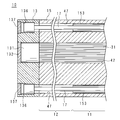
- FIG. 3 is a partial cross-sectional view of the endoscope 10 taken along the line III-III in FIG.
- the flexible tube 15 is connected to the surface of the disc-shaped tip portion 13 on the side of the operation portion.
- the flexible tube 15 is a so-called multi-lumen tube in which a plurality of through holes such as the cable hole 42 and the curved wire hole 47 penetrate in the longitudinal direction.
- the flexible tube 11 and the bending section 12 are covered with a flexible tube 15. As shown by a broken line in FIG. 1, the operation portion side of the flexible tube 15 is arranged inside the operation portion 20.
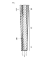
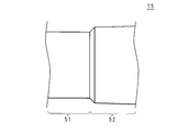
- FIG. 4 is a front view of the flexible tube 15.
- the flexible tube 15 has a first region 51 having a uniform thickness, a tapered second region 52 on the side of the first region 51, and a third region 53 continuous with the second region 52.
- the first area 51 is the exterior of the bending portion 12
- the second area 52 is the exterior of the flexible portion 11
- the third area 53 is the exterior of the folding portion 16 and the operating portion 20. It is placed inside.
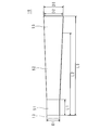
- FIG. 5 is a side view of the flexible tube 15.
- the flexible tube 15 has an illumination hole 43, an air supply hole 44, a water supply hole 45, a channel hole 48, and a sub water supply channel hole 49 in addition to the above-described cable hole 42 and four curved wire holes 47.
- the lighting hole 43 communicates with the lighting window 133, and the fiber bundle is arranged inside.
- the air supply hole 44 communicates with the air supply nozzle 134.
- the water supply hole 45 communicates with the water supply nozzle 135.
- the channel hole 48 communicates with the channel outlet 18.
- the sub water supply channel hole 49 communicates with the sub water supply channel outlet 19.
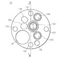
- FIG. 6 is a sectional view of the flexible tube 15 taken along the line VI-VI in FIG.
- the outer shape of the flexible tube 15 is tapered, but the through holes such as the curved wire hole 47 and the cable hole 42 have uniform inner diameters and are arranged in parallel with each other. ing.
- FIG. 7 is an enlarged cross-sectional view of part A in FIG.
- the portion A is a boundary portion between the first area 51 and the second area 52.
- the surface of the tube body 151 is exposed in the first region 51, and the surface of the tube body 151 is covered with the flexible tube outer layer 152 in the second region 52.
- the tube body 151 is a resin multi-lumen tube manufactured by extrusion molding or the like.
- the tube body 151 is made of, for example, PTFE (PolyTetraFluoroEtylene), ePTFE (expanded Poly Tetra FluoroEtylene), PE (Polyethylene), HDPTFE (High Density Poly Tetra FluoroEtylene), PP (Polypropylene), PU (Polyurethane) or PA (Polyurethane). It is made of any resin material such as Polyamide).
- the tube body 151 may be made of a copolymer in which any resin material is combined.
- the tube body 151 may be manufactured by multi-layer molding in which arbitrary resin materials are combined.
- the outer flexible tube layer 152 is made of a material harder than the tube body 151.
- the flexible tube 15 is manufactured by covering the tube body 151 with a flexible tube outer layer 152 made of a heat-shrinkable tube, and curing and shrinking the outer layer 152.
- the flexible tube 15 may be manufactured by covering the tube body 151 with the flexible tube outer layer 152 made of an elastic tube having an inner diameter slightly smaller than the small diameter portion of the tube body 151.
- the tube body 151 can be inserted into the elastic tube by temporarily expanding the outer diameter of the elastic tube using a jig.
- the outer flexible tube layer 152 may be manufactured by spirally winding a resin tape having high hardness such as hard polyethylene around the surface of the tube body 151.
- the flexible tube outer layer 152 may be a resin layer manufactured by applying a resin material having high hardness to the surface of the tube body 151.
- the flexible outer layer 152 may be a film such as a DLC (Diamond-like Carbon) film formed on the surface of the tube body 151.
- FIG. 8 is an explanatory diagram illustrating the flexibility of the flexible tube 15.
- the third region 53 side of the flexible tube 15 is placed and fixed on a flat desk 61, and the length of the first region 51 and the second region 52 is about twice that of the second region 52.
- It is a schematic diagram which shows the state which made the part hang down from the edge of the desk 61 by its own weight.
- the second area 52 hangs slightly due to its own weight. Since the first region 51 is more flexible than the second region 52, it bends downward due to its own weight and hangs down.
- the flexible tube outer layer 152 provided in the second region 52 functions as a rigidity imparting portion that imparts rigidity to the flexible portion 11.
- the diameter of the flexible tube 15 on the first region 51 side is D1
- the diameter of the boundary between the second region 52 and the third region 53 is D2
- the diameter on the third region 53 side is D3.
- the length of the first region 51 is L1
- the length from the end face on the first region 51 side to the boundary between the second region 52 and the third region 53 is L2
- the total length is L3.
- L3 is a value about 50 mm to 200 mm larger than L2.
- FIG. 9 is a graph illustrating the dimensions of the flexible tube 15.
- the horizontal axis represents the length X measured from the end on the tip side.
- the vertical axis represents the diameter Y of the flexible tube 15.
- the diameter Y is D1.
- the relationship between the length X and the diameter Y is a linear function indicated by a straight line on the graph.
- the graph showing the relationship between the length X and the diameter Y in the second region 52 may be a polygonal line in which the inclination becomes large on the way.
- the relationship between the length X and the diameter Y in the second region 52 and the third region 53 may be a quadratic or higher function.
- the relationship between the length X and the diameter Y may be any function different from that of the second region 52.
- the diameter Y may be a constant value such as D2 or D1.
- the tip side may be thinner than the operating portion side.
- Table 1 shows dimension examples of L1, L2, D1 and D2. For L3 and D3, dimensional examples are omitted. The unit is millimeter. The dimensions shown in Table 1 are examples, and the dimensions are not limited thereto.
- No. No. 1 is a colonoscope
- No. 2 is an upper gastrointestinal endoscope
- Reference numeral 3 denotes the size of the flexible tube 15 which is suitable for the duodenoscope.
- an imaging unit 131 including a lens, an imaging element, a driver circuit, and the like is arranged on the operation unit side of the observation window 132.
- the cable bundle 31 connected to the imaging unit 131 extends into the cable hole 42.
- the wire lid 137 is attached to the stepped hole 136 provided in the tip portion 13.
- the stepped hole 136 has two steps on the inner surface thereof, has a small diameter on the operation portion side, and communicates with the bending wire hole 47. That is, the tip end side of the curved wire hole 47 is closed by the stepped hole 136 and the wire lid 137.
- the bending wire 17 having a stopper at the first end is arranged inside the bending wire hole 47.
- the bending wire 17 is prevented from coming off by a thickness that does not pass through the small-diameter portion of the stepped hole 136, and the bending wire 17 does not come off to the operation portion side.
- a lens and a fiber bundle are arranged on the side of the operation portion of the illumination window 133.
- the fiber bundle extends into the illumination hole 43.
- a cable bundle 31, a fiber bundle, etc. are inserted inside the connector portion 24, the universal cord 25, the operation portion 20, and the insertion portion 14.
- the illumination light emitted from the light source device is emitted from the illumination window 133 via the fiber bundle.
- the range illuminated by the illumination light is imaged by the imaging unit 131 through the observation window 132.
- a video signal is transmitted from the imaging unit 131 to the endoscope processor via the cable bundle 31.
- the tubes inserted inside the universal cord 25 are connected to the air supply hole 44, the water supply hole 45, and the sub water supply channel hole 49 inside the operation unit 20, respectively.
- the air supplied from the air / water supply device is discharged toward the observation window 132 from the air supply nozzle 134 via the tube in the universal cord 25 and the air supply hole 44.
- the water supplied from the air / water supply device is discharged from the water supply nozzle 135 toward the observation window 132 via the tube in the universal cord 25 and the water supply hole 45.
- the water supplied from the air / water supply device is discharged from the auxiliary water supply channel outlet 19 toward the observation target site through the tube in the universal cord 25 and the auxiliary water supply channel hole 49.
- the air supply nozzle 134 and the water supply nozzle 135 are used, for example, for cleaning the observation window 132 during an endoscopic examination.
- the water supply from the sub-water supply channel outlet 19 is used for washing away the residue, mucus, blood and the like from the observation target site.
- the channel inlet 22 and the channel hole 48 are connected by a tube (not shown).
- a treatment tool (not shown) from the channel inlet 22
- the distal end of the treatment tool can be projected from the channel outlet 18 to perform a procedure such as excision of a large intestine polyp.
- the second end of the bending wire 17 described using FIG. 3 is connected to the bending knob 21 inside the operation unit 20.
- the bending knob 21 is an example of a pulling mechanism that pulls the bending wire 17 toward the operation unit side.
- FIG. 10 is an explanatory diagram illustrating the curved shape of the insertion portion 14.
- the thickness and hardness of the built-in components such as the cable bundle 31, the fiber bundle, and the bending wire 17 are uniform.
- the first region 51 of the flexible tube 15 is flexible enough to hang down due to its own weight, and the second region 52 is harder than the first region 51.
- the flexible tube 15 bends toward the pulled bending wire 17.
- the portion corresponding to the first region 51 functions as the bending portion 12
- the portion corresponding to the second region 52 functions as the flexible portion 11.
- the layout of the end face of the tip portion 13 described with reference to FIG. 2 is an example, and the layout is not limited to this.
- the number of the illumination windows 133 may be one or three or more.
- the number of bending wires 17 may be two.
- a so-called two-direction curved endoscope 10 can be provided.
- the endoscope 10 does not have to include the auxiliary water supply channel hole 49 and the auxiliary water supply channel outlet 19.
- the endoscope 10 may be a side-view type or a perspective type.
- the endoscope 10 may have a forceps raising mechanism.
- the endoscope 10 having a small number of parts. Since the cable bundle 31 and the fiber bundle are inserted into the cable hole 42 and the illumination hole 43, which are independent through holes, respectively, and a plurality of tubes are not used in the insertion portion 14, the internal components are arranged inside the insertion portion 14. It is possible to prevent the failure due to the disturbance. Further, since there is no fear that the arrangement of the built-in objects is disturbed during the assembly, it is possible to provide the endoscope 10 which can be easily assembled.
- the surface of the flexible portion 11 and the surface of the bending portion 12 are configured by the flexible tube 15 which is integrated, the surface of the boundary portion between the flexible portion 11 and the bending portion 12 is smooth, and the endoscope 10 that is easy to insert. Can be provided.
- parts other than the cable bundle 31 and the fiber bundle in the flexible portion 11 and the bending portion 12 are made of resin, it is possible to provide the endoscope 10 that is light in weight and does not tire the doctor who uses it.
- the doctor can twist the insertion part 14 with a light force, so-called twisting operation. Since the flexible tube 15 has an integral structure, the twisting operation performed on the operating portion side is directly transmitted to the bending portion 12. Therefore, it is possible to provide the endoscope 10 in which a doctor who is used is less tired and is easy to perform an endoscopic examination.
- the insertion portion 14 and the flexible tube 15 may have a uniform thickness as a whole. Since the material of the tube body 151 that is made long by extrusion molding can be cut to a desired length and used, the material of the tube body 151 can be reduced.
- the present embodiment relates to an endoscope 10 in which a light emitting element such as an LED (Light Emitting Diode) is provided on a tip portion 13. Descriptions of portions common to the first embodiment will be omitted.
- a light emitting element such as an LED (Light Emitting Diode)
- the tip portion 13 of the present embodiment has a light emitting element on the operation portion side of the illumination window 133.
- the light emitted from the light emitting element is emitted from the illumination window 133.
- the illumination window 133 and the light emitting element may be integrated.
- FIG. 11 is a side view of the flexible tube 15 according to the second embodiment.
- the flexible tube 15 of this embodiment does not include the illumination hole 43.
- a part of the cable included in the cable bundle 31 inserted through the cable hole 42 is connected to the light emitting element to supply electric power.
- the endoscope 10 having the light emitting element at the tip. Since the fiber bundle and the light source device are unnecessary, an inexpensive endoscopic inspection device can be provided. Since the fiber bundle is not used, it is possible to provide the endoscope 10 in which the insertion portion 14 has a reduced diameter.
- the present embodiment relates to the endoscope 10 in which a cable for a light emitting element is inserted into the illumination hole 43. Descriptions of parts common to the second embodiment will be omitted.
- FIG. 12 is a side view of the flexible tube 15 according to the third embodiment.
- the flexible tube 15 of the present embodiment includes one illumination hole 43.
- a cable for the light emitting element is inserted into the illumination hole 43.
- the endoscope 10 since it is not necessary to divide the cable bundle 31 into the image pickup unit 131 and the light emitting element, it is possible to provide the endoscope 10 that can be easily assembled.
- the present embodiment relates to the endoscope 10 using a tube body 151 having a uniform thickness. Descriptions of portions common to the first embodiment will be omitted.
- FIG. 13 is a sectional view of the flexible tube 15 according to the fourth embodiment.
- the tube main body 151 of the present embodiment has a uniform thickness, and the flexible tube outer layer 152 is thicker on the operating portion side.
- the material of the tube body 151 which is formed in a long length by extrusion molding, can be cut into a desired length and used, so that the waste of the material of the tube body 151 can be reduced.
- the material of the tube body 151 can be commonly used even in the endoscope 10 in which there are variations in the length of the insertion portion 14 such as a colonoscope.
- the present embodiment relates to the endoscope 10 using a flexible material for the first region 51. Descriptions of portions common to the first embodiment will be omitted.
- FIG. 14 is a sectional view of the flexible tube 15 according to the fifth embodiment.
- the 1st field 51 of this embodiment is constituted by the 1st tube body 1511, and the 2nd field 52 and the 3rd field 53 are constituted by the 2nd tube body 1512.
- the flexible tube 15 does not have the flexible tube outer layer 152.
- the first tube body 1511 is made of a resin that is more flexible than the second tube body 1512, and both are integrally molded. Since the first tube body 1511 is flexible, when the bending wire 17 is pulled, the bending portion 12 bends similarly to FIG. 10.
- the second tube body 1512 functions as a rigidity imparting portion.
- the flexible tube 15 of the present embodiment may have the flexible tube outer layer 152.
- the flexible tube 15 may have a uniform thickness as a whole.
- the present embodiment relates to the endoscope 10 including the inner sheath 153 on the inner surface of the curved wire hole 47. Descriptions of portions common to the first embodiment will be omitted.
- FIG. 15 is a partial cross-sectional view of the endoscope 10 according to the sixth embodiment.
- an inner sheath 153 is provided inside the bending wire hole 47, and the bending wire 17 is arranged in the inner sheath 153.
- the inner sheath 153 is an elastic body having higher rigidity than the flexible tube 15, such as a hollow coil or a resin tube.
- the bending portion 12 is more flexible than the flexible portion 11 in which the inner sheath 153 is present, when the bending wire 17 is pulled, the bending portion 12 bends as in FIG. 10.
- the inner sheath 153 functions as a rigidity imparting portion.
- the flexible tube 15 of the present embodiment may or may not have the flexible tube outer layer 152.
- the flexible tube 15 may have a uniform thickness as a whole.
- the present embodiment relates to the endoscope 10 having a distal end hole 154 on the distal end side of the flexible tube 15. Descriptions of portions common to the first embodiment will be omitted.
- FIG. 16 is a partial cross-sectional view of the endoscope 10 according to the seventh embodiment.
- the flexible tube 15 is provided with a plurality of tip holes 154 from the tip side by, for example, laser processing or thermal processing.
- the tip hole 154 is provided to increase the inner diameter of a through hole such as the curved wire hole 47.
- the tip hole 154 may be provided in a place where the through hole does not exist so as not to interfere with the through hole.
- the tip hole 154 may be a non-circular hole such as an oval shape or an elliptical shape.
- the flexible tube 15 has a small cross-sectional area, so it is easily bent. Since the curved portion having the tip hole 154 is softer than the flexible portion 11 having no tip hole 154, when the bending wire 17 is pulled, the bending portion 12 bends as in FIG. 10. That is, the portion of the flexible tube 15 where the tip hole 154 is not provided functions as a rigidity imparting portion.
- the flexible tube 15 of the present embodiment may or may not have the flexible tube outer layer 152.
- the flexible tube 15 may have a uniform thickness as a whole.
- the present embodiment relates to the endoscope 10 in which a flexible tube 15 is further provided with a through hole. Descriptions of portions common to the first embodiment will be omitted.
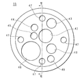
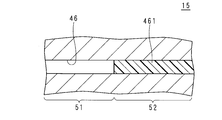
- FIG. 17 is a side view of the flexible tube 15 according to the eighth embodiment.
- 18 is a cross-sectional view of the flexible tube 15 taken along the line XVIII-XVIII in FIG.
- the flexible tube 15 of the present embodiment has adjustment holes 46 on the upper side and the lower side of the bending wire hole 47 on the right side in FIG. 17 and on the upper right side of the bending wire hole 47 on the left side.
- the adjustment hole 46 is a through hole that penetrates the flexible tube 15 in the longitudinal direction.
- the reinforcing body 461 is arranged in the adjustment hole 46.
- the reinforcing body 461 is, for example, a resin that is injected into the adjustment hole 46 and cured.
- the reinforcing body 461 may be any elastic body having a higher rigidity than the flexible tube 15, such as a metal or resin wire or tube fixed by being inserted into the adjustment hole 46 from the operation portion side.
- the reinforcement body 461 may be attached to the flexible tube 15 in advance or may be attached in the assembly process of the endoscope 10.
- the reinforcement body 461 functions as a rigidity imparting portion.
- the flexible tube 15 of the present embodiment may or may not have the flexible tube outer layer 152.
- the flexible tube 15 may have a uniform thickness as a whole.
- the present embodiment relates to the endoscope 10 in which the flexible portion 11 is thicker than the bending portion 12 at the boundary between the bending portion 12 and the flexible portion 11. Descriptions of portions common to the first embodiment will be omitted.
- FIG. 19 is a front view of the flexible tube 15 according to the ninth embodiment.
- FIG. 20 is an enlarged view of part B in FIG.
- the flexible tube 15 has a first region 51 having a uniform thickness, a tapered second region 52 on the side of the first region 51, and a third region 53 continuous with the second region 52.
- the second region 52 is thicker than the first region 51 at the boundary between the first region 51 and the second region 52.
- the step between the two is tapered by chamfering.
- the first region 51 is the exterior of the bending portion 12
- the second region 52 is the exterior of the flexible portion 11. That is, the flexible portion 11 is thicker than the bending portion 12 at the boundary between the bending portion 12 and the flexible portion 11 of the endoscope 10.
- the second area 52 functions as a rigidity imparting portion.
- the present embodiment there is a clear difference in flexibility of the flexible tube 15 at the boundary between the first region 51 and the second region 52. Therefore, it is possible to provide the endoscope 10 in which the operation portion side of the bending portion 12 bends with a small radius of curvature.
- FIG. 21 is a partially enlarged view of a modified example of the flexible tube 15 of the ninth embodiment.
- the step at the boundary between the first region 51 and the second region 52 is not chamfered.
Landscapes
- Health & Medical Sciences (AREA)
- Life Sciences & Earth Sciences (AREA)
- Physics & Mathematics (AREA)
- Surgery (AREA)
- Optics & Photonics (AREA)
- Biomedical Technology (AREA)
- Animal Behavior & Ethology (AREA)
- Radiology & Medical Imaging (AREA)
- Nuclear Medicine, Radiotherapy & Molecular Imaging (AREA)
- Engineering & Computer Science (AREA)
- Biophysics (AREA)
- Heart & Thoracic Surgery (AREA)
- Medical Informatics (AREA)
- Molecular Biology (AREA)
- Pathology (AREA)
- General Health & Medical Sciences (AREA)
- Public Health (AREA)
- Veterinary Medicine (AREA)
- Astronomy & Astrophysics (AREA)
- General Physics & Mathematics (AREA)
- Endoscopes (AREA)
- Instruments For Viewing The Inside Of Hollow Bodies (AREA)
Abstract
L'invention concerne un endoscope comportant moins d'éléments. Un endoscope (10) est pourvu d'une unité d'actionnement (20) et d'une unité d'insertion (14) à laquelle est reliée une extrémité de l'unité d'actionnement (20). L'unité d'insertion (14) comprend : une partie d'extrémité distale (13) située à l'extrémité distale de l'unité d'insertion (14) ; un tube à plusieurs lumières qui relie la partie d'extrémité distale (13) et l'unité d'actionnement (20) et est pourvu d'une pluralité de trous traversants qui comprennent un trou de fil fléchisseur (47) et s'étendent dans la direction longitudinale ; un fil fléchisseur (17) qui passe à travers le trou de fil fléchisseur (47) et a une première extrémité fixée à la partie d'extrémité distale (13) et une seconde extrémité reliée à un mécanisme de traction (21) disposé sur l'unité d'actionnement (20) ; et une partie conférant une rigidité qui est disposée en continu à partir d'une position espacée d'une distance prédéterminée de l'extrémité du tube à plusieurs lumières du côté partie distale (13) à l'extrémité du côté unité d'actionnement (20). Le côté unité d'actionnement est plus épais que le côté partie d'extrémité distale.
Applications Claiming Priority (2)
| Application Number | Priority Date | Filing Date | Title |
|---|---|---|---|
| JP2018211675A JP2020075043A (ja) | 2018-11-09 | 2018-11-09 | 内視鏡 |
| JP2018-211675 | 2018-11-09 |
Publications (1)
| Publication Number | Publication Date |
|---|---|
| WO2020096035A1 true WO2020096035A1 (fr) | 2020-05-14 |
Family
ID=70611278
Family Applications (1)
| Application Number | Title | Priority Date | Filing Date |
|---|---|---|---|
| PCT/JP2019/043825 WO2020096035A1 (fr) | 2018-11-09 | 2019-11-08 | Endoscope |
Country Status (2)
| Country | Link |
|---|---|
| JP (1) | JP2020075043A (fr) |
| WO (1) | WO2020096035A1 (fr) |
Citations (5)
| Publication number | Priority date | Publication date | Assignee | Title |
|---|---|---|---|---|
| JPH0894941A (ja) * | 1994-09-27 | 1996-04-12 | Asahi Optical Co Ltd | 内視鏡の湾曲部 |
| JPH09285441A (ja) * | 1996-04-24 | 1997-11-04 | Olympus Optical Co Ltd | 内視鏡 |
| JP2005081100A (ja) * | 2003-09-11 | 2005-03-31 | Olympus Corp | 内視鏡の可撓管 |
| JP2007082743A (ja) * | 2005-09-22 | 2007-04-05 | Pentax Corp | 内視鏡の可撓性挿入管及びその製造方法 |
| WO2019044186A1 (fr) * | 2017-08-31 | 2019-03-07 | オリンパス株式会社 | Partie d'insertion d'endoscope |
-
2018
- 2018-11-09 JP JP2018211675A patent/JP2020075043A/ja active Pending
-
2019
- 2019-11-08 WO PCT/JP2019/043825 patent/WO2020096035A1/fr active Application Filing
Patent Citations (5)
| Publication number | Priority date | Publication date | Assignee | Title |
|---|---|---|---|---|
| JPH0894941A (ja) * | 1994-09-27 | 1996-04-12 | Asahi Optical Co Ltd | 内視鏡の湾曲部 |
| JPH09285441A (ja) * | 1996-04-24 | 1997-11-04 | Olympus Optical Co Ltd | 内視鏡 |
| JP2005081100A (ja) * | 2003-09-11 | 2005-03-31 | Olympus Corp | 内視鏡の可撓管 |
| JP2007082743A (ja) * | 2005-09-22 | 2007-04-05 | Pentax Corp | 内視鏡の可撓性挿入管及びその製造方法 |
| WO2019044186A1 (fr) * | 2017-08-31 | 2019-03-07 | オリンパス株式会社 | Partie d'insertion d'endoscope |
Also Published As
| Publication number | Publication date |
|---|---|
| JP2020075043A (ja) | 2020-05-21 |
Similar Documents
| Publication | Publication Date | Title |
|---|---|---|
| US6623424B2 (en) | Flexible tube for an endoscope and electronic endoscope equipped with the flexible tube | |
| EP1554972B1 (fr) | Dispositif endoscopique | |
| US20060200000A1 (en) | Endoscope | |
| AU2006213225A1 (en) | Flexible tube for endoscope, and endoscope device | |
| US20130046144A1 (en) | Flexible tube unit of endoscope and endoscope having this flexible tube unit | |
| US8221312B2 (en) | Endoscope | |
| WO2020008900A1 (fr) | Endoscope | |
| JP2006280602A (ja) | 内視鏡 | |
| EP2517615A1 (fr) | Tube à disposer dans des endoscopes, et endoscope | |
| EP2870909A1 (fr) | Endoscope | |
| EP3135182A1 (fr) | Section de courbure d'endoscope et endoscope | |
| JPWO2013172089A1 (ja) | 内視鏡システム | |
| CN110545708B (zh) | 内窥镜弯曲部和内窥镜 | |
| US4336794A (en) | Guide tube | |
| JP4801434B2 (ja) | 内視鏡用可撓管 | |
| US20100063357A1 (en) | Endoscope insertion aid, endoscope apparatus and endoscope apparatus insertion method | |
| WO2020096035A1 (fr) | Endoscope | |
| JP2009066299A (ja) | 内視鏡 | |
| JP4017925B2 (ja) | 超音波内視鏡 | |
| JP5810037B2 (ja) | 内視鏡システム | |
| JP5331424B2 (ja) | 内視鏡 | |
| JP5283463B2 (ja) | 内視鏡 | |
| WO2019044186A1 (fr) | Partie d'insertion d'endoscope | |
| JP2002058637A (ja) | 内視鏡用可撓管 | |
| JP7122848B2 (ja) | 内視鏡 |
Legal Events
| Date | Code | Title | Description |
|---|---|---|---|
| 121 | Ep: the epo has been informed by wipo that ep was designated in this application |
Ref document number: 19882003 Country of ref document: EP Kind code of ref document: A1 |
|
| NENP | Non-entry into the national phase |
Ref country code: DE |
|
| 122 | Ep: pct application non-entry in european phase |
Ref document number: 19882003 Country of ref document: EP Kind code of ref document: A1 |