WO2020090314A1 - 血圧測定装置 - Google Patents
血圧測定装置 Download PDFInfo
- Publication number
- WO2020090314A1 WO2020090314A1 PCT/JP2019/038388 JP2019038388W WO2020090314A1 WO 2020090314 A1 WO2020090314 A1 WO 2020090314A1 JP 2019038388 W JP2019038388 W JP 2019038388W WO 2020090314 A1 WO2020090314 A1 WO 2020090314A1
- Authority
- WO
- WIPO (PCT)
- Prior art keywords
- cuff
- blood pressure
- curler
- sheet member
- measurement device
- Prior art date
- Legal status (The legal status is an assumption and is not a legal conclusion. Google has not performed a legal analysis and makes no representation as to the accuracy of the status listed.)
- Ceased
Links
Images


Classifications
-
- A—HUMAN NECESSITIES
- A61—MEDICAL OR VETERINARY SCIENCE; HYGIENE
- A61B—DIAGNOSIS; SURGERY; IDENTIFICATION
- A61B5/00—Measuring for diagnostic purposes; Identification of persons
- A61B5/02—Detecting, measuring or recording for evaluating the cardiovascular system, e.g. pulse, heart rate, blood pressure or blood flow
- A61B5/021—Measuring pressure in heart or blood vessels
- A61B5/022—Measuring pressure in heart or blood vessels by applying pressure to close blood vessels, e.g. against the skin; Ophthalmodynamometers
- A61B5/02233—Occluders specially adapted therefor
-
- A—HUMAN NECESSITIES
- A61—MEDICAL OR VETERINARY SCIENCE; HYGIENE
- A61B—DIAGNOSIS; SURGERY; IDENTIFICATION
- A61B5/00—Measuring for diagnostic purposes; Identification of persons
- A61B5/68—Arrangements of detecting, measuring or recording means, e.g. sensors, in relation to patient
- A61B5/6801—Arrangements of detecting, measuring or recording means, e.g. sensors, in relation to patient specially adapted to be attached to or worn on the body surface
- A61B5/6802—Sensor mounted on worn items
- A61B5/681—Wristwatch-type devices
-
- A—HUMAN NECESSITIES
- A61—MEDICAL OR VETERINARY SCIENCE; HYGIENE
- A61B—DIAGNOSIS; SURGERY; IDENTIFICATION
- A61B5/00—Measuring for diagnostic purposes; Identification of persons
- A61B5/02—Detecting, measuring or recording for evaluating the cardiovascular system, e.g. pulse, heart rate, blood pressure or blood flow
- A61B5/021—Measuring pressure in heart or blood vessels
- A61B5/02141—Details of apparatus construction, e.g. pump units or housings therefor, cuff pressurising systems, arrangements of fluid conduits or circuits
-
- A—HUMAN NECESSITIES
- A61—MEDICAL OR VETERINARY SCIENCE; HYGIENE
- A61B—DIAGNOSIS; SURGERY; IDENTIFICATION
- A61B5/00—Measuring for diagnostic purposes; Identification of persons
- A61B5/02—Detecting, measuring or recording for evaluating the cardiovascular system, e.g. pulse, heart rate, blood pressure or blood flow
- A61B5/021—Measuring pressure in heart or blood vessels
- A61B5/022—Measuring pressure in heart or blood vessels by applying pressure to close blood vessels, e.g. against the skin; Ophthalmodynamometers
- A61B5/02233—Occluders specially adapted therefor
- A61B5/02241—Occluders specially adapted therefor of small dimensions, e.g. adapted to fingers
-
- A—HUMAN NECESSITIES
- A61—MEDICAL OR VETERINARY SCIENCE; HYGIENE
- A61B—DIAGNOSIS; SURGERY; IDENTIFICATION
- A61B5/00—Measuring for diagnostic purposes; Identification of persons
- A61B5/68—Arrangements of detecting, measuring or recording means, e.g. sensors, in relation to patient
- A61B5/6801—Arrangements of detecting, measuring or recording means, e.g. sensors, in relation to patient specially adapted to be attached to or worn on the body surface
- A61B5/6813—Specially adapted to be attached to a specific body part
- A61B5/6824—Arm or wrist
-
- A—HUMAN NECESSITIES
- A61—MEDICAL OR VETERINARY SCIENCE; HYGIENE
- A61B—DIAGNOSIS; SURGERY; IDENTIFICATION
- A61B5/00—Measuring for diagnostic purposes; Identification of persons
- A61B5/68—Arrangements of detecting, measuring or recording means, e.g. sensors, in relation to patient
- A61B5/6801—Arrangements of detecting, measuring or recording means, e.g. sensors, in relation to patient specially adapted to be attached to or worn on the body surface
- A61B5/6844—Monitoring or controlling distance between sensor and tissue
-
- A—HUMAN NECESSITIES
- A61—MEDICAL OR VETERINARY SCIENCE; HYGIENE
- A61B—DIAGNOSIS; SURGERY; IDENTIFICATION
- A61B2560/00—Constructional details of operational features of apparatus; Accessories for medical measuring apparatus
- A61B2560/02—Operational features
- A61B2560/0204—Operational features of power management
- A61B2560/0214—Operational features of power management of power generation or supply
-
- A—HUMAN NECESSITIES
- A61—MEDICAL OR VETERINARY SCIENCE; HYGIENE
- A61B—DIAGNOSIS; SURGERY; IDENTIFICATION
- A61B2562/00—Details of sensors; Constructional details of sensor housings or probes; Accessories for sensors
- A61B2562/02—Details of sensors specially adapted for in-vivo measurements
- A61B2562/0247—Pressure sensors
-
- A—HUMAN NECESSITIES
- A61—MEDICAL OR VETERINARY SCIENCE; HYGIENE
- A61B—DIAGNOSIS; SURGERY; IDENTIFICATION
- A61B2562/00—Details of sensors; Constructional details of sensor housings or probes; Accessories for sensors
- A61B2562/16—Details of sensor housings or probes; Details of structural supports for sensors
- A61B2562/164—Details of sensor housings or probes; Details of structural supports for sensors the sensor is mounted in or on a conformable substrate or carrier
-
- A—HUMAN NECESSITIES
- A61—MEDICAL OR VETERINARY SCIENCE; HYGIENE
- A61B—DIAGNOSIS; SURGERY; IDENTIFICATION
- A61B5/00—Measuring for diagnostic purposes; Identification of persons
- A61B5/02—Detecting, measuring or recording for evaluating the cardiovascular system, e.g. pulse, heart rate, blood pressure or blood flow
- A61B5/021—Measuring pressure in heart or blood vessels
- A61B5/022—Measuring pressure in heart or blood vessels by applying pressure to close blood vessels, e.g. against the skin; Ophthalmodynamometers
- A61B5/0235—Valves specially adapted therefor
Definitions
- the blood pressure measuring device described above a wearable device worn on the wrist has been considered recently. For this reason, it is not preferable that the blood pressure measuring device be increased in size by increasing the joining margin provided on the cuff or curler.
- the joint margin is increased, so that the joint strength of the cuff and the curler can be improved.
- the blood pressure measurement device in which the front first facing portion is configured to have a shape wider in the width direction than other portions of the curler. According to this aspect, by increasing the joint area, the blood pressure measuring device is increased in size by making the first facing portion, which increases the joint area in the curler, a region facing the end of the outer case in the thickness direction. It can be prevented.
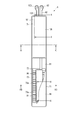
- the case 11 includes an outer case 31, a windshield 32 that covers an upper opening of the outer case 31, a base portion 33 provided below the inside of the outer case 31, and a lower side of the outer case 31. And a back cover 35 that covers the.
- the base 33 holds the display unit 12, the operation unit 13, the pump 14, the opening / closing valve 16, the pressure sensor 17, the power supply unit 18, the vibration motor 19, and the control board 20. Further, the base portion 33 constitutes, for example, a part of the flow passage portion 15 that fluidly connects the pump 14 and the cuff structure body 6.
- the back cover 35 covers the living body side end of the outer case 31.
- the back cover 35 is fixed to the living body side end of the outer case 31 or the base 33 by, for example, four screws 35a.
- the surface shape of the back surface 35b of the back cover 35 is circular because the outer case 31 is formed in a cylindrical shape.
- the diameter of the back cover 35 is smaller than the diameter of the outer case 31. In other words, the length of the back cover 35 along the width direction of the curler 5 is shorter than the length of the outer case 31 along the width direction of the curler 5.
- the operation unit 13 is configured to be able to input a command from the user.
- the operation unit 13 includes a plurality of buttons 41 provided on the case 11, a sensor 42 that detects an operation of the buttons 41, and a touch panel 43 provided on the display unit 12 or the windshield 32. , Is provided.
- the operation unit 13 is operated by a user to convert a command into an electric signal.
- the sensor 42 and the touch panel 43 are electrically connected to the control board 20 and output an electric signal to the control board 20.
- the pump 14 is, for example, a piezoelectric pump.
- the pump 14 compresses air and supplies the compressed air to the cuff structure 6 via the flow path portion 15.
- the pump 14 is electrically connected to the control board 20.
- the on-off valve 16 opens and closes a part of the flow path section 15.
- a plurality of on-off valves 16 are provided, for example, as shown in FIG. 5, and a combination of opening and closing of each on-off valve 16 connects the pump 14 to the flat cuff 71 and the instep cuff 74, and connects the pump 14 to the sensing cuff 73.
- the flow path, the flow path from the flat cuff 71 and the instep cuff 74 to the atmosphere, and the flow path from the sensing cuff 73 to the atmosphere are selectively opened and closed.
- two on-off valves 16 are used.
- the pressure sensor 17 detects the pressure of the flat cuff 71, the sensing cuff 73, and the instep cuff 74.
- the pressure sensor 17 is electrically connected to the control board 20.
- the pressure sensor 17 converts the detected pressure into an electric signal and outputs it to the control board 20.
- the pressure sensor 17 is provided in a flow path connecting the pump 14 to the flat cuff 71 and the instep cuff 74 and a flow path connecting the pump 14 to the sensing cuff 73.
- the power supply unit 18 is, for example, a secondary battery such as a lithium ion battery.
- the power supply unit 18 is electrically connected to the control board 20.
- the power supply unit 18 supplies power to the control board 20.
- the acceleration sensor 52 is, for example, a triaxial acceleration sensor.
- the acceleration sensor 52 outputs an acceleration signal representing accelerations of the device body 3 in three directions orthogonal to each other to the control unit 55.
- the acceleration sensor 52 is used to measure the activity amount of the living body wearing the blood pressure measurement device 1 from the detected acceleration.
- the network is, for example, the Internet, but is not limited to this, and may be a network such as a LAN (Local Area Network) provided in a hospital, or a predetermined standard such as USB. It may be a direct communication with an external device using a cable having terminals. Therefore, the communication unit 53 may be configured to include a plurality of wireless antennas and micro USB connectors.
- LAN Local Area Network
- USB Universal Serial Bus
- the control unit 55 has a main CPU (Central Processing Unit) 56 that controls the operation of the entire blood pressure measurement device 1 and a sub CPU 57 that controls the operation of the fluid circuit 7.
- the main CPU 56 obtains a measurement result such as a blood pressure value such as systolic blood pressure and diastolic blood pressure or a heart rate from the electric signal output from the pressure sensor 17, and outputs an image signal corresponding to the measurement result to the display unit 12. .
- a measurement result such as a blood pressure value such as systolic blood pressure and diastolic blood pressure or a heart rate
- the sub CPU 57 drives the pump 14 and the opening / closing valve 16 to send compressed air to the flat cuff 71 and the sensing cuff 73. Further, the sub CPU 57 controls driving and stopping of the pump 14 and opening / closing of the open / close valve 16 based on the electric signal output from the pressure sensor 17. The sub CPU 57 controls the pump 14 and the opening / closing valve 16 to selectively send compressed air to the flat cuff 71 and the sensing cuff 73, and selectively depressurize the flat cuff 71 and the sensing cuff 73.
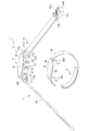
- the first belt 61 is called a so-called parent and is configured in a belt shape.
- the first belt 61 is provided at one end of the first belt 61 and is orthogonal to the longitudinal direction of the first belt 61, and the other end of the first belt 61 is orthogonal to the longitudinal direction of the first belt 61. It has two holes 61b and a buckle 61c provided in the second hole 61b.
- the first hole portion 61a has an inner diameter into which the spring rod 31b can be inserted and the first belt 61 can rotate with respect to the spring rod 31b. That is, the first belt 61 is rotatably held in the outer shell case 31 between the pair of lugs 31a and by disposing the first hole portion 61a in the spring rod 31b.
- the second hole 61b is provided at the tip of the first belt 61.
- the buckle 61c has a rectangular frame-shaped frame 61d and a stick 61e rotatably attached to the frame 61d.
- One side of the frame-shaped body 61d, to which the stick 61e is attached, is inserted into the second hole portion 61b and is rotatably attached with respect to the first belt 61.
- the second belt 62 is a so-called sword tip, and is configured in a belt shape having a width that can be inserted into the frame-shaped body 61d. Further, the second belt 62 has a plurality of small holes 62a into which the sticks 61e are inserted.
- the second belt 62 has a third hole portion 62b provided at one end portion thereof and orthogonal to the longitudinal direction of the second belt 62.
- the third hole 62b has an inner diameter into which the spring rod 31b can be inserted and the second belt 62 can rotate with respect to the spring rod 31b. That is, the second belt 62 is rotatably held in the outer case 31 by being disposed between the pair of lugs 31a and by disposing the third hole portion 62b in the spring rod 31b.
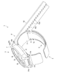
- the curler 5, as shown in FIG. 4, is configured in a band shape that curves along the circumferential direction of the wrist.
- the curler 5 is formed such that one end and the other end are separated from each other.
- the curler 5 has, for example, an outer surface on one end side fixed to the back cover 35 of the apparatus body 3.
- the curler 5 is arranged at a position where one end and the other end of the curler 5 project beyond the case back 35. Further, the curlers 5 are separated by a predetermined distance, and one end and the other end are adjacent to each other.
- the curler 5 has a first facing portion 5a.
- the first facing portion 5 a faces the back cover 35.
- the first facing portion 5a is arranged in the axial direction of the outer case 31 at the end of the outer case.
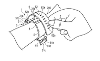
- the curler 5 is, for example, a circumference of the wrist 200 in a side view from a direction orthogonal to the circumferential direction of the wrist, in other words, a longitudinal direction of the wrist 200. It has a shape that curves along a direction.
- the curler 5 extends from the device body 3 to the palm side of the wrist 200 through the back side of the wrist 200 and one side side of the wrist 200, and extends to the other side side of the wrist 200, for example. That is, the curler 5 is arranged along most of the circumferential direction of the wrist 200 by being curved along the circumferential direction of the wrist 200, and both ends thereof are separated by a predetermined distance.
- the curler 5 has hardness having flexibility and shape retention.
- the flexibility means that the shape is deformed in the radial direction when an external force of the belt 4 is applied to the curler 5.
- flexibility means that when the curler 5 is pressed by the belt 4, the curler 5 approaches the wrist, follows the shape of the wrist, or deforms the shape in a side view so as to follow the shape of the wrist.
- the shape-retaining property means that the curler 5 can maintain a preshaped shape when an external force is not applied.
- the outer shape retaining property means that in the present embodiment, the shape of the curler 5 can be maintained to be curved along the circumferential direction of the wrist.
- the curler 5 has a cuff structure 6 arranged on the inner peripheral surface thereof, and holds the cuff structure 6 along the inner peripheral surface shape of the curler 5.
- the flat cuff 71 and the instep cuff 74 are arranged on the inner peripheral surface, and the flat cuff 71 and the instep cuff 74 are joined by the joining member 8.
- the curler 5 is made of a resin material.
- the curler 5 is formed of, for example, a thermoplastic resin material, specifically, polypropylene.
- the curler 5 is formed to have a thickness of, for example, about 1 mm.
- the cuff structure 6 includes a flat cuff (cuff) 71, a back plate 72, a sensing cuff 73, and an instep cuff (cuff) 74. ing.
- the cuff structure 6 is fixed to the curler 5.
- a flat cuff 71, a back plate 72 and a sensing cuff 73 are stacked and arranged on the curler 5, and an instep cuff 74 is arranged on the curler 5 while being separated from the flat cuff 71, the back plate 72 and the sensing cuff 73. To be done.
- a flat cuff 71, a back plate 72, a sensing cuff 73, and an instep cuff 74 are arranged on the inner surface of the curler 5.
- the cuff structure 6 is fixed on the palm-side inner surface of the wrist 200 of the curler 5 by laminating the flat cuff 71, the back plate 72, and the sensing cuff 73 in this order from the inner surface of the curler 5 toward the living body.
- an instep cuff 74 is arranged on the inner surface of the back side of the wrist 200 of the curler 5.
- Each member of the cuff structure 6 is fixed to a member adjacent in the stacking direction with a double-sided tape or an adhesive.
- the flat cuff 71 is a so-called pressing cuff.
- the flat cuff 71 is fluidly connected to the pump 14 via the flow path portion 15.
- the flat cuff 71 expands to press the back plate 72 and the sensing cuff 73 toward the living body.
- the flat cuff 71 includes a plurality of, for example, two layers of air bags 81, and a plurality of insertion holes 82 provided in the air bag 81 of the two layers of air bags 81 arranged on the curler 5 side.
- the air bag 81 is a bag-shaped structure, and in the present embodiment, since the blood pressure measurement device 1 is configured to use air by the pump 14, it will be described using the air bag, but other than air.
- the bag-shaped structure may be a fluid bag such as a liquid bag.
- the plurality of air bags 81 are stacked and fluidly communicate with each other in the stacking direction.
- the air bag 81 is formed in a rectangular shape that is long in one direction.
- the air bag 81 is configured by, for example, combining two sheet members 86 that are long in one direction and welding the edges by heat. That is, the air bag 81 has a welded portion 81a in which the peripheral portions of the four sides are welded.
- the two-layer air bladder 81 includes a first sheet member 86a and a second sheet bladder 81 that constitutes the first sheet member 86a and the first-layer air bag 81 from the living body side.
- a sheet member 86b, a third sheet member 86c that is integrally bonded to the second sheet member 86b, and a fourth sheet member 86d that constitutes the third sheet member 86c and the second-layer air bag 81 are provided.
- the two-layer air bag 81 is integrally configured by joining the sheet members 86 of the adjacent air bags 81 by double-sided tape, adhesive bonding or welding.
- the first sheet member 86a and the second sheet member 86b form the air bag 81 by welding the peripheral portions of the four sides.
- the second sheet member 86b and the third sheet member 86c are arranged to face each other, and each has a plurality of openings 86b1 and 86c1 that fluidly connect the two air bags 81.
- the third sheet member 86c and the fourth sheet member 86d form the air bag 81 by welding the peripheral portions of the four sides.
- the back plate 72 is attached to the outer surface of the first sheet member 86a of the flat cuff 71 with an adhesive layer, double-sided tape or the like.
- the back plate 72 is formed of a resin material in a plate shape.
- the back plate 72 is made of polypropylene, for example, and is formed into a plate shape having a thickness of about 1 mm.
- the back plate 72 has a shape following property.
- the shape-following property refers to a function of allowing the back plate 72 to be deformed so as to follow the shape of the contacted portion of the wrist 200 to be arranged, and the back plate 72 faces the contacted portion of the wrist 200.
- the area of the wrist 200 is referred to, and the contact here includes both direct contact and indirect contact via the sensing cuff 73.
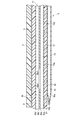
- the back plate 72 has a plurality of grooves 72a extending in a direction orthogonal to the longitudinal direction on both main surfaces of the back plate 72.
- a plurality of grooves 72a are provided on both main surfaces of the back plate 72, respectively.
- the plurality of grooves 72a provided on both main surfaces face each other in the thickness direction of the back plate 72.
- the plurality of grooves 72a are arranged at equal intervals in the longitudinal direction of the back plate 72.
- the back plate 72 is formed to have a length that covers the palm side of the wrist 200.
- the back plate 72 transmits the pressing force from the flat cuff 71 to the main surface of the sensing cuff 73 on the back plate 72 side while conforming to the shape of the wrist 200.
- the sensing cuff 73 is fixed to the main surface of the back plate 72 on the living body side.
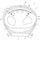
- the sensing cuff 73 is in direct contact with the region of the wrist 200 where the artery 210 is present, as shown in FIGS. 9 and 14.
- the artery 210 is a radial artery and an ulnar artery.
- the sensing cuff 73 is formed in the same shape as the back plate 72 or in a shape smaller than the back plate 72 in the longitudinal direction and the width direction of the back plate 72.
- the sensing cuff 73 When the sensing cuff 73 is inflated, the sensing cuff 73 presses the area where the palm side artery 210 of the wrist 200 is present.
- the sensing cuff 73 is pressed toward the living body by the expanded flat cuff 71 via the back plate 72.
- the sensing cuff 73 includes one air bag 91, a tube 92 that communicates with the air bag 91, and a connecting portion 93 provided at the tip of the tube 92.
- the sensing cuff 73 has one main surface of the air bag 91 fixed to the back plate 72.
- the sensing cuff 73 is attached to the main surface of the back plate 72 on the living body side with a double-sided tape, an adhesive layer, or the like.
- the air bag 91 is a bag-shaped structure, and in the present embodiment, since the blood pressure measurement device 1 is configured to use air by the pump 14, the description will be given using the air bag, but other than air.
- the bag-shaped structure may be a liquid bag or the like.
- the air bag 91 is formed in a rectangular shape that is long in one direction.
- the air bag 91 is configured by, for example, combining two sheet members 96 that are long in one direction and welding the edges by heat.
- the air bag 91 includes a fifth sheet member 96a and a sixth sheet member 96b from the living body side.
- the tube 92 that is fluidly continuous with the internal space of the air bag 91 is arranged on one side of the fifth sheet member 96a and the sixth sheet member 96b, and is welded. Fixed.
- the peripheral portions of the four sides are welded in a state where the tube 92 is arranged between the fifth sheet member 96a and the sixth sheet member 96b to form the air bag 91.
- the tube 92 is integrally welded.
- the tube 92 is provided at one end of the air bag 91 in the longitudinal direction.
- the tube 92 is provided at an end portion of the air bag 91 near the apparatus body 3.
- the tube 92 has a connecting portion 93 at its tip.
- the tube 92 is connected to the flow path portion 15 and constitutes a flow path between the apparatus body 3 and the air bag 91.
- the connection part 93 is connected to the flow path part 15.
- the connecting portion 93 is, for example, a nipple.
- the instep cuff 74 is a so-called pulling cuff.
- the instep cuff 74 is fluidly connected to the pump 14 via the flow path portion 15.
- the instep cuff 74 expands to press the curler 5 so as to separate from the wrist 200, thereby pulling the belt 4 and the curler 5 toward the back side of the wrist 200.
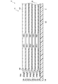
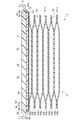
- the instep cuff 74 includes a plurality of, for example, six layers of air bags 101, a tube 102 that communicates with the air bag 101, and a connecting portion 103 provided at the tip of the tube 102.
- the instep cuff 74 is in the inflating direction, in the present embodiment, the direction in which the curler 5 and the wrist 200 are opposed to each other, and the inflated thickness is the inflated thickness in the inflating direction of the flat cuff 71, and the sensing. It is configured to be thicker than the thickness of the cuff 73 in the inflating direction. That is, the air bag 101 of the instep cuff 74 has a layered structure larger than that of the air bag 81 of the flat cuff 71 and the air bag 91 of the sensing cuff 73, and has a thickness when inflated from the curler 5 toward the wrist 200. It is thicker than the flat cuff 71 and the sensing cuff 73.
- the air bag 101 is a bag-shaped structure, and in the present embodiment, since the blood pressure measuring device 1 has a configuration in which air is used by the pump 14, it will be described using an air bag, but other than air.
- the bag-shaped structure may be a fluid bag such as a liquid bag.
- the plurality of air bags 101 are stacked and fluidly communicate with each other in the stacking direction.
- the air bag 101 is formed in a rectangular shape that is long in one direction.
- the air bag 101 is configured by, for example, combining two sheet members 106 that are long in one direction and welding the edges by heat. That is, the air bag 101 has a welded portion 101a in which the peripheral portions of the four sides are welded.
- the six-layer air bag 101 includes a seventh sheet member 106a, an eighth sheet member 106b, a ninth sheet member 106c, and a tenth sheet member 106d from the living body side.
- the six-layered air bag 101 is integrally configured by joining the sheet members 106 of the adjacent air bags 101 by adhering or welding with a double-sided tape, an adhesive or the like.
- the seventh sheet member 106a and the eighth sheet member 106b form the air bag 101 of the first layer by welding the peripheral portions of the four sides.
- the eighth sheet member 106b and the ninth sheet member 106c are arranged facing each other and are integrally bonded.
- the eighth sheet member 106b and the ninth sheet member 106c have a plurality of openings 106b1 and 106c1 that fluidly connect the adjacent air bags 101.
- the ninth sheet member 106c and the tenth sheet member 106d constitute the second-layer air bag 101 by welding the peripheral portions of the four sides.
- the tenth sheet member 106d and the eleventh sheet member 106e are arranged facing each other and are integrally bonded.
- the tenth sheet member 106d and the eleventh sheet member 106e have a plurality of openings 106d1 and 106e1 that fluidly connect the adjacent air bags 101.
- the eleventh sheet member 106e and the twelfth sheet member 106f constitute the third-layer air bag 101 by welding the peripheral portions of the four sides.
- the twelfth sheet member 106f and the thirteenth sheet member 106g are arranged facing each other and are integrally bonded.
- the twelfth sheet member 106f and the thirteenth sheet member 106g have a plurality of openings 106f1 and 106g1 for fluidly connecting the adjacent air bags 101.
- the thirteenth sheet member 106g and the fourteenth sheet member 106h form the fourth-layer air bag 101 by welding the peripheral portions of the four sides.
- the 14th sheet member 106h and the 15th sheet member 106i are arranged to face each other and are integrally bonded.
- the fourteenth sheet member 106h and the fifteenth sheet member 106i have a plurality of openings 106h1 and 106i1 that fluidly connect the adjacent air bags 101.
- the fifteenth sheet member 106i and the sixteenth sheet member 106j form the fifth-layer air bag 101 by welding the peripheral portions of the four sides.
- the 16th sheet member 106j and the 17th sheet member 106k are arranged so as to face each other and are integrally bonded.
- the sixteenth sheet member 106j and the seventeenth sheet member 106k have a plurality of openings 106j1 and 106k1 that fluidly connect the adjacent air bags 101.
- the seventeenth sheet member 106k and the eighteenth sheet member 106l form the sixth-layer air bag 101 by welding the peripheral portions in a rectangular frame shape.
- the eighteenth sheet member 106l is arranged on the curler 5 side.
- the tube 102 that is fluidly continuous with the internal space of the air bag 101 is arranged on one side of the seventeenth sheet member 106k and the eighteenth sheet member 106l, and is fixed by welding.
- the seventeenth sheet member 106k and the eighteenth sheet member 106l are welded at their peripheral portions in a rectangular frame shape while the tube 102 is arranged between the seventeenth sheet member 106k and the eighteenth sheet member 106l to form the air bag 101.
- the tube 102 is integrally welded by molding.
- such a sixth layer air bag 101 is configured integrally with the second layer air bag 81 of the flat cuff 71. That is, the seventeenth sheet member 106k is integrally formed with the third sheet member 86c, and the eighteenth sheet member 106l is integrally formed with the fourth sheet member 86d.
- the third sheet member 86c and the seventeenth sheet member 106k constitute a rectangular sheet member that is long in one direction
- the eighteenth sheet member 106l and the fourth sheet member 86d are rectangular sheets that are long in one direction.
- a shaped sheet member is configured.
- these sheet members are overlapped with each other, and one end portion side is formed into a rectangular frame shape, and a part of one side on the other end portion side is removed and welded.
- the air bag 81 of the second layer of the flat cuff 71 is configured.
- the other end side has a rectangular frame shape, and is welded except for a part of one side of the one end side, thereby forming the sixth-layer air bag 101 of the instep cuff 74. ..
- the second-layer air bag 81 and the sixth-layer air bag 101 are fluidly continuous because part of one side facing each other is not welded.
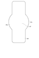
- the eighteenth sheet member 106l has a second facing portion 107 joined to the first facing portion 5a of the curler 5.
- the second facing portion 107 is a portion of the eighteenth sheet member 106l that faces the first facing portion 5a, and is wider in the width direction than a portion of the eighteenth sheet member 106l that does not face the first facing portion 5a. It has a wide shape.
- the surface shape of the second facing portion 107 is configured to be larger than the surface shape of the first facing portion 5a.
- the second facing portion 107 has a second wing portion 107a extending in the width direction as compared with the portions on both sides of the second facing portion 107 in the longitudinal direction of the eighteenth sheet member 106l.
- the second wing 107a is formed on each side of the eighteenth sheet member 106l in the width direction.
- the second wing portion 107a is, for example, configured to have an arc-shaped edge having a larger diameter than the arc-shaped edge of the first wing portion 5b of the first facing portion 5a.
- the second facing portion 107 is joined to the first facing portion 5a by being bonded to the first facing portion 5a with an adhesive layer 108 made of an adhesive material or a double-sided tape. Since the surface shape of the second wing portion 107a is configured to be larger than the surface shape of the first wing portion 5b, the second wing portion 107a is bonded by the adhesive layer 108, and thus the first wing portion 107a is bonded. It is joined to the back surface 5c of 5b, the side surface 5d of the first wing portion 5b, and the back surface 35b of the back cover 35. The region of the second facing portion 107 excluding the second wing portion 107a is bonded to the region of the first facing portion 5a excluding the first wing portion 5b by being bonded with the adhesive layer 108.
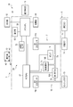
- the fluid circuit 7 includes a case 11, a pump 14, a flow path section 15, an opening / closing valve 16, a pressure sensor 17, a flat cuff 71, a sensing cuff 73, and an instep cuff 74.
- the two on-off valves 16 used in the fluid circuit 7 are a first on-off valve 16A and a second on-off valve 16B, and the two pressure sensors 17 are a first pressure sensor 17A and a second pressure sensor 17B. A specific example will be described.
- FIG. 15 is a flowchart showing an example of blood pressure measurement using the blood pressure measurement device 1, and shows both the user's operation and the operation of the control unit 55.
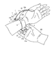
- 16 to 18 show an example in which the user wears the blood pressure measurement device 1 on the wrist 200.
- the user wears the blood pressure measurement device 1 on the wrist 200 (step ST1).
- the user inserts one of the wrists 200 into the curler 5, as shown in FIG.
- the sensing cuff 73 is arranged in the region where the palm side artery 210 of the wrist 200 exists.
- the device body 3 and the back cuff 74 are arranged on the back side of the wrist 200.
- the user passes the second belt 62 through the frame-shaped body 61d of the buckle 61c of the first belt 61 with the hand opposite to the hand on which the blood pressure measurement device 1 is placed.
- the user pulls the second belt 62 to bring the member on the inner peripheral surface side of the curler 5, that is, the cuff structure 6 into close contact with the wrist 200, and inserts the rod 61e attached to the small hole 62a.
- the first belt 61 and the second belt 62 are connected, and the blood pressure measurement device 1 is attached to the wrist 200.
- the user operates the operation unit 13 to input a command corresponding to the start of blood pressure measurement.
- the operation unit 13 that has performed the instruction input operation outputs an electric signal corresponding to the start of measurement to the control unit 55 (step ST2).
- the control unit 55 receives the electric signal, for example, the first opening / closing valve 16A is opened, the second opening / closing valve 16B is closed, the pump 14 is driven, and the first passage 7a and the second passage 7b are passed through.
- the compressed air is supplied to the flat cuff 71, the sensing cuff 73, and the instep cuff 74 (step ST3).
- the flat cuff 71, the sensing cuff 73, and the instep cuff 74 start to inflate.
- the first pressure sensor 17A and the second pressure sensor 17B detect the pressures of the flat cuff 71, the sensing cuff 73, and the instep cuff 74, respectively, and output an electric signal corresponding to this pressure to the control unit 55 (step ST4).
- the control unit 55 determines whether the pressure in the internal space of the flat cuff 71, the sensing cuff 73 and the instep cuff 74 has reached a predetermined pressure for blood pressure measurement based on the received electric signal (step ST5). ).
- the control unit 55 turns on the first opening / closing valve 16A. It is closed and compressed air is supplied through the first flow path 7a.
- the instep cuff 74 presses the curler 5 in the direction away from the wrist 200
- the belt 4, the curler 5 and the device body 3 move in the direction away from the wrist 200, and as a result, the flat cuff 71, The back plate 72, the sensing cuff 73, and the flat plate 75 are pulled toward the wrist 200.
- the belt 4, the curler 5 and the device body 3 move in a direction away from the wrist 200 due to the expansion of the instep cuff 74, the belt 4 and the curler 5 move toward both sides of the wrist 200, and the wrist
- the belt 4, the curler 5, and the apparatus main body 3 move in a state of being closely attached to both sides of 200. Therefore, the belt 4 and the curler 5 that are in close contact with the skin of the wrist 200 pull the skin on both sides of the wrist 200 toward the back side of the hand.
- the sensing cuff 73 is inflated and supplied with a predetermined amount of air so that the internal pressure becomes the pressure required to measure the blood pressure, and the back plate 72 pressed by the flat cuff 71 causes the sensing cuff 73 to reach the wrist 200. It is pressed toward. Therefore, the sensing cuff 73 presses the artery 210 in the wrist 200 and closes the artery 210 as shown in FIG.
- control unit 55 controls the inside of the flat cuff 71 by controlling the second opening / closing valve 16B and repeating opening / closing of the second opening / closing valve 16B, or by adjusting the opening degree of the second opening / closing valve 16B, for example.
- the pressure in the space is increased.
- the control unit 55 obtains measurement results such as blood pressure values such as systolic blood pressure and diastolic blood pressure, heart rate, etc. based on the electric signal output from the second pressure sensor 17B (step ST6).
- the control unit 55 outputs the image signal corresponding to the obtained measurement result to the display unit 12 and displays the measurement result on the display unit 12 (step ST7). Further, the control unit 55 opens the first opening / closing valve 16A and the second opening / closing valve 16B after the blood pressure measurement is completed.
- the first facing portion 5a of the curler 5 has the first wing portion 5b, and the eighteenth portion is disposed on the curler 5 side of the instep cuff 74.
- the second facing portion 107 of the sheet member 106l has a second wing portion 107a. Then, the second wing portion 107a is bonded to the first wing portion 5b by being bonded to the first wing portion 5b by the adhesive layer 108.
- the wing portions 5a1 and 107a increase the joint area for joining the instep cuff 74 and the curler 5. Therefore, the blood pressure measurement device 1 can improve the joint strength between the instep cuff 74 and the curler 5.
- the joining margin is increased only for a part of the curler 5 and the instep cuff 74, so that the blood pressure measurement device 1 can be prevented from being upsized.
- the surface shape of the second facing portion 107 is formed to be wider than the surface shape of the first facing portion 5a, and a part of the second wing portion 107a is also fixed to the back cover 35. Since the instep cuff 74 can be directly joined to the case 11, the fixing strength of the instep cuff 74 to the case 11 can be improved.
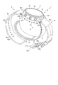
- the blood pressure measurement device 1 according to the second embodiment has a configuration in which the curler 5 and the back cover 35 are integrally formed, and in this respect is different from the blood pressure measurement device 1 according to the first embodiment described above. ..
- a curler having a shape in which the curler 5 and the back cover 35 are integrally formed is referred to as a curler 5A.
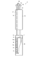
- FIG. 19 is an exploded perspective view showing the configuration of the blood pressure measurement device 1 according to the second embodiment.
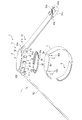
- FIG. 20 is a cross-sectional view showing the configuration of the blood pressure measurement device 1 according to the second embodiment.
- the curler 5A is formed in a band shape that curves along the circumferential direction of the wrist.
- the curler 5A is formed such that one end and the other end are separated from each other.
- the curler 5A has a lid 5e that covers the living body-side end of the outer case 31.
- the curler 5A is arranged at a position where one end and the other end project beyond the lid 5e. Further, the curler 5A is separated by a predetermined distance, and one end and the other end are adjacent to each other.
- the lid 5e is fixed to the living body side end of the outer case 31 or the base 33 using a screw 35a or the like.
- the lid 5e is provided on the curler 5A so that one end and the other end of the curler 5A are located on one side of the wrist 200 when the blood pressure measurement device 1 is attached to the wrist 200. Fixed to.
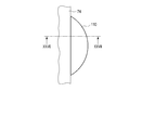
- a notch 5h is formed on the arc-shaped edge of the back surface 5g of the third wing 5f of the lid 5e on the wrist 200 side. Since the notch portion 5h is formed on the back surface 5g, the vicinity of the edge of the back surface 5g is formed as a step.
- the back surface 5g configured in this manner has, for example, the same shape as the surface on the wrist 200 side of the one body of the back cover 35f of the blood pressure measurement device 1 according to the first embodiment and the first facing portion 5a of the curler 5. Composed.
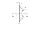
- the surface shape of the third wing portion 5f is not limited to the configuration in which the edge has an arc shape.
- the third blade portion 5f may have a rectangular surface shape, for example.
- the curler 5A has, for example, a shape orthogonal to the circumferential direction of the wrist, that is, curved along the circumferential direction of the wrist 200 in a side view from the longitudinal direction of the wrist 200.
- the curler 5A extends, for example, from the device body 3 to the palm side of the wrist 200 through the back side of the wrist 200 and one side side of the wrist 200, and extends to the other side side of the wrist 200. That is, the curler 5 is arranged along most of the circumferential direction of the wrist 200 by being curved along the circumferential direction of the wrist 200, and both ends thereof are separated by a predetermined distance.
- the curler 5A has hardness having flexibility and shape retention.
- the flexibility means that the shape is deformed in the radial direction when the external force of the belt 4 is applied to the curler 5A.
- “flexibility” means that when the curler 5A is pressed by the belt 4, the curler 5A is close to the wrist, follows the shape of the wrist, or deforms the shape in a side view so as to follow the shape of the wrist.
- the shape-retaining property means that the curler 5A can maintain a preshaped shape when an external force is not applied.
- the outer shape maintaining property means that in the present embodiment, the shape of the curler 5A can be maintained in a shape that curves along the circumferential direction of the wrist.
- the curler 5A has the cuff structure 6 arranged on the inner peripheral surface thereof, and holds the cuff structure 6 along the inner peripheral surface shape of the curler 5.
- the flat cuff 71 and the instep cuff 74 are arranged on the inner peripheral surface, and the flat cuff 71 and the instep cuff 74 are joined by the joining member 8.
- the curler 5A is made of a resin material.
- the curler 5A is formed of, for example, a thermoplastic resin material, specifically, polypropylene.
- the curler 5 is formed to have a thickness of, for example, about 1 mm.
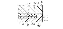
- the curler 5A configured as described above has, for example, a configuration in which the back cover 35 and the facing portion 5a of the blood pressure measurement device 1 according to the first embodiment are integrally formed.
- the surface shape of the second facing portion 107A is, for example, larger than the surface shape of the lid portion 5e.
- the second facing portion 107A has the second wing portion 107a1 extending in the width direction as compared with the portions on both sides of the second facing portion 107A in the longitudinal direction of the eighteenth sheet member 106l.
- the second wing portions 107a are formed one on each side in the width direction of the eighteenth sheet member 106l.
- the second wing portion 107a1 is configured to have a planar shape having an arc-shaped edge having a larger diameter than the arc of the edge of the third wing portion 5f of the lid portion 5e.
- the second opposing portion 107A is joined to the lid portion 5e by being adhered to the lid portion 5e by an adhesive layer 108 made of an adhesive material or a double-sided tape. Since the surface shape of the second facing portion 107A is configured to be larger than the surface shape of the first facing portion 5a, the second wing portion 107a1 is adhered by the adhesive layer 108, so that the lid portion 5e of the lid portion 5e. It is joined to the third wing portion 5f. Further, as an example, the second wing 107a1 is also joined to the cutout portion 5h of the third wing 5f. The region of the second facing portion 107A excluding the second wing portion 107a1 is joined to the region of the lid portion 5e excluding the third wing portion 5f by being adhered by the adhesive layer 108.
- the second wing portion 107a1 has been described as having a configuration in which a part thereof is joined to the cutout portion 5h of the lid portion 5e, but the present invention is not limited to this.
- the second wing portion 107a1 may have a shape that is joined to a region other than the cutout portion 5h on the back surface 5g of the third wing portion 5f on the wrist 200 side.
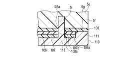
- the blood pressure measurement device 1 according to the second embodiment configured as described above has the same effects as those of the first embodiment. Furthermore, the number of parts that configure the blood pressure measurement device 1 can be reduced. [Third Embodiment] Next, a third embodiment of the blood pressure measurement device 1 will be described with reference to FIGS. 21 and 22. In the blood pressure measurement device 1 according to the third embodiment, the second blade portion 107a1 of the eighteenth sheet member 106l of the instep cuff 74 is sandwiched between the third blade portion 5f of the lid portion 5e of the curler 5A. The configuration is different from that of the blood pressure measurement device 1 according to the second embodiment described above.
- the same configurations as those of the blood pressure measurement device 1 according to the first embodiment described above will be denoted by the same reference numerals, and the description and Illustration is omitted as appropriate.
- FIG. 21 is a bottom view of the vicinity of one of the two second wing portions 107a1 of the instep cuff 74 as seen from the wrist 200 side.
- 22 is a cross-sectional view showing one of the two second wing portions 107a of the instep cuff 74, which is a cross-sectional view taken along the line XXII-XXII shown in FIG.
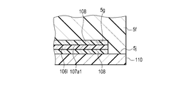
- the blood pressure measurement device 1 further includes two cover members 110 in addition to the configuration of the second embodiment.
- the cover member 110 sandwiches the second wing portion 107a1 with the third wing portion 5f.
- the surface shape of the cover member 110 is configured such that a part of the outer edge is formed in an arc shape and the remaining part is formed in a linear shape.
- the cover member 110 has an arc-shaped edge facing the arc-shaped edge of the lid 5e.
- the diameter of the arc-shaped edge of the cover member 110 is the same as the diameter of the arc-shaped edge of the lid 5e.
- the cover member 110 has an edge portion 111 configured to have an arc-shaped edge.
- the height of the edge portion 111 is higher than that of other portions.
- the edge portion 111 is arranged in the cutout portion 5h of the lid portion 5e. The height mentioned here is the height from the back surface 112 of the cover member 110 on the wrist 200 side.
- the height of the edge portion 111 is such that when the tip of the edge portion 111 is joined to the cutout portion 5h by the adhesive layer 108, the area other than the edge portion 111 of the cover member 110 and the third blade portion of the lid portion 5e.
- the adhesive layer 108 and the second wing portion 107a1 are dimensioned to be sandwiched between the regions other than the cutout portion 5h of 5f.
- the edge portion 111 is bonded to the cutout portion 5h of the lid portion 5e by the adhesive layer 108. Further, on the surface of the cover member 110 on the lid portion 5e side, regions other than the edge portion 111 are bonded to the second wing portion 107a1 by being bonded by the bonding layer 108.
- FIG. 28 is a bottom view of the vicinity of one of the two second wing portions 107a1 of the instep cuff 74 as seen from the wrist 200 side.
- FIG. 29 is a cross-sectional view showing the configuration in the vicinity of one of the two second wing parts 107a1 of the instep cuff 74, and is a cross-sectional view taken along the line XXIV-XXIV shown in FIG.
- the first arc surface portion 5k1 is the largest diameter portion of the side surface 5k.
- the second arc surface portion 5k2 is configured as an arc surface having a curvature center on the same axis as the curvature center of the first arc surface portion 5k1.
- the second arc surface portion 5k2 is configured to have an arc surface having a smaller diameter than the first arc surface portion 5k1.
- the third arc surface portion 5k3 is configured as an arc surface having a curvature center coaxial with the curvature center of the first arc surface portion 5k1.
- the third arc surface portion 5k3 is configured to have an arc surface having a smaller diameter than the second arc surface portion 5k2.
- the cover member 110 is bonded by bonding the edge portion 111 to the region of the second blade portion 107a1 that is bonded to the second back surface portion 5g2 with the bonding layer 108.
- the area other than the edge portion 111 of the cover member 110 is bonded to the area of the second wing portion 107a bonded to the first back surface portion 5b1 by being bonded by the bonding layer 108.
- the outer case 31 has a part of the cover member 110 and the lid 5e fitted therein.
- the fixing strength of the curler 5A and the case 11 and the fixing strength of the cover member 110 and the case 11 are improved. It becomes possible. Furthermore, since the joint between the cover member 110 and the lid 5e is covered by the outer case 31, the sealability at the joint between the cover member 110 and the lid 5e can be improved.
- the joining portion mentioned here is a portion including the line end surface of the edge portion 111, the adhesive layer 108, and the second back surface portion 5g2.
- the second wing portion 107a may be joined to the lid 5e by a joining member.
- the joining member is a member that mechanically joins the two members, and includes, for example, a caulking protrusion, a rivet, and a sewing thread.
- Second on-off valve 17 Pressure sensor 17A ... First pressure sensor 17B ... Second pressure sensor 18 ... Power supply part 19 ... Vibration motor 20 ... Control board 31 ... Outer case 31a ... Lug 31b ... Spring rod 32 ... Windshield 33 ... Base 35 ... Back cover 35a ... Screw 41 ... Button 42 ... Sensor 43 ... Touch panel 51 ... Board 52 ... Acceleration sensor 53 ... Communication section 54 ... Storage section 55 ... Control part 61 ... 1st belt 61a ... 1st hole 61b ... 2nd hole 61c ... Buckle 61d ... Frame-shaped body 61e ... Stick rod 62 ... 2nd belt 62a ... Small hole 62b ...
Landscapes
- Health & Medical Sciences (AREA)
- Life Sciences & Earth Sciences (AREA)
- Cardiology (AREA)
- Surgery (AREA)
- General Health & Medical Sciences (AREA)
- Engineering & Computer Science (AREA)
- Biomedical Technology (AREA)
- Heart & Thoracic Surgery (AREA)
- Medical Informatics (AREA)
- Molecular Biology (AREA)
- Physics & Mathematics (AREA)
- Animal Behavior & Ethology (AREA)
- Pathology (AREA)
- Public Health (AREA)
- Veterinary Medicine (AREA)
- Biophysics (AREA)
- Vascular Medicine (AREA)
- Physiology (AREA)
- Ophthalmology & Optometry (AREA)
- Dentistry (AREA)
- Measuring Pulse, Heart Rate, Blood Pressure Or Blood Flow (AREA)
Priority Applications (3)
| Application Number | Priority Date | Filing Date | Title |
|---|---|---|---|
| CN201980063655.4A CN112788987A (zh) | 2018-10-30 | 2019-09-27 | 血压测定装置 |
| DE112019004833.3T DE112019004833T5 (de) | 2018-10-30 | 2019-09-27 | Blutdruckmessvorrichtung |
| US17/224,427 US20210236012A1 (en) | 2018-10-30 | 2021-04-07 | Blood pressure measurement device |
Applications Claiming Priority (2)
| Application Number | Priority Date | Filing Date | Title |
|---|---|---|---|
| JP2018-204204 | 2018-10-30 | ||
| JP2018204204A JP7154949B2 (ja) | 2018-10-30 | 2018-10-30 | 血圧測定装置 |
Related Child Applications (1)
| Application Number | Title | Priority Date | Filing Date |
|---|---|---|---|
| US17/224,427 Continuation US20210236012A1 (en) | 2018-10-30 | 2021-04-07 | Blood pressure measurement device |
Publications (1)
| Publication Number | Publication Date |
|---|---|
| WO2020090314A1 true WO2020090314A1 (ja) | 2020-05-07 |
Family
ID=70464039
Family Applications (1)
| Application Number | Title | Priority Date | Filing Date |
|---|---|---|---|
| PCT/JP2019/038388 Ceased WO2020090314A1 (ja) | 2018-10-30 | 2019-09-27 | 血圧測定装置 |
Country Status (5)
| Country | Link |
|---|---|
| US (1) | US20210236012A1 (enExample) |
| JP (1) | JP7154949B2 (enExample) |
| CN (1) | CN112788987A (enExample) |
| DE (1) | DE112019004833T5 (enExample) |
| WO (1) | WO2020090314A1 (enExample) |
Families Citing this family (2)
| Publication number | Priority date | Publication date | Assignee | Title |
|---|---|---|---|---|
| US11744476B2 (en) | 2020-08-20 | 2023-09-05 | Apple Inc. | Blood pressure measurement using device with piezoelectric sensor |
| US12251204B2 (en) | 2021-02-03 | 2025-03-18 | Apple Inc. | Blood pressure monitoring system including a liquid filled sensor |
Citations (6)
| Publication number | Priority date | Publication date | Assignee | Title |
|---|---|---|---|---|
| JPS60126138A (ja) * | 1983-12-14 | 1985-07-05 | 松下電工株式会社 | 血圧計の排気弁 |
| WO2004080299A1 (ja) * | 2003-03-11 | 2004-09-23 | Terumo Kabushiki Kaisha | 血圧計用カフ及びそれを備えた血圧計 |
| WO2007074589A1 (ja) * | 2005-12-27 | 2007-07-05 | Omron Healthcare Co., Ltd. | 血圧計用カフおよびこれを備えた血圧計 |
| WO2016101888A1 (zh) * | 2014-12-24 | 2016-06-30 | 深圳瑞光康泰科技有限公司 | 气囊袖带及自动血压测量装置 |
| JP2018102859A (ja) * | 2016-12-28 | 2018-07-05 | オムロン株式会社 | 血圧計および血圧測定方法並びに機器 |
| JP2018521761A (ja) * | 2015-07-08 | 2018-08-09 | セルイージス デバイシィズ インコーポレイテッドCellaegis Devices Inc. | 対象における遠隔虚血コンディショニング(ric)を実行するために設定可能なシステム |
Family Cites Families (4)
| Publication number | Priority date | Publication date | Assignee | Title |
|---|---|---|---|---|
| JP4595526B2 (ja) * | 2004-12-20 | 2010-12-08 | オムロンヘルスケア株式会社 | 血圧計用カフおよび血圧計 |
| JP4595525B2 (ja) * | 2004-12-20 | 2010-12-08 | オムロンヘルスケア株式会社 | 血圧計用カフおよびこれを備えた血圧計 |
| WO2016044459A1 (en) * | 2014-09-16 | 2016-03-24 | St. Luke Medical, Inc. | Blood pressure cuff with tapered bladder |
| JP6830353B2 (ja) * | 2016-12-28 | 2021-02-17 | オムロン株式会社 | 血圧計および血圧測定方法並びに機器 |
-
2018
- 2018-10-30 JP JP2018204204A patent/JP7154949B2/ja active Active
-
2019
- 2019-09-27 DE DE112019004833.3T patent/DE112019004833T5/de active Pending
- 2019-09-27 CN CN201980063655.4A patent/CN112788987A/zh active Pending
- 2019-09-27 WO PCT/JP2019/038388 patent/WO2020090314A1/ja not_active Ceased
-
2021
- 2021-04-07 US US17/224,427 patent/US20210236012A1/en active Pending
Patent Citations (6)
| Publication number | Priority date | Publication date | Assignee | Title |
|---|---|---|---|---|
| JPS60126138A (ja) * | 1983-12-14 | 1985-07-05 | 松下電工株式会社 | 血圧計の排気弁 |
| WO2004080299A1 (ja) * | 2003-03-11 | 2004-09-23 | Terumo Kabushiki Kaisha | 血圧計用カフ及びそれを備えた血圧計 |
| WO2007074589A1 (ja) * | 2005-12-27 | 2007-07-05 | Omron Healthcare Co., Ltd. | 血圧計用カフおよびこれを備えた血圧計 |
| WO2016101888A1 (zh) * | 2014-12-24 | 2016-06-30 | 深圳瑞光康泰科技有限公司 | 气囊袖带及自动血压测量装置 |
| JP2018521761A (ja) * | 2015-07-08 | 2018-08-09 | セルイージス デバイシィズ インコーポレイテッドCellaegis Devices Inc. | 対象における遠隔虚血コンディショニング(ric)を実行するために設定可能なシステム |
| JP2018102859A (ja) * | 2016-12-28 | 2018-07-05 | オムロン株式会社 | 血圧計および血圧測定方法並びに機器 |
Also Published As
| Publication number | Publication date |
|---|---|
| JP2020068993A (ja) | 2020-05-07 |
| JP7154949B2 (ja) | 2022-10-18 |
| US20210236012A1 (en) | 2021-08-05 |
| CN112788987A (zh) | 2021-05-11 |
| DE112019004833T5 (de) | 2021-06-10 |
Similar Documents
| Publication | Publication Date | Title |
|---|---|---|
| JP7019415B2 (ja) | 血圧測定装置 | |
| WO2020095990A1 (ja) | 血圧測定装置 | |
| JP6896610B2 (ja) | 血圧測定装置 | |
| JP6976842B2 (ja) | 血圧測定装置 | |
| WO2020090314A1 (ja) | 血圧測定装置 | |
| US12064221B2 (en) | Blood pressure measurement device | |
| US20210212580A1 (en) | Blood pressure measurement device | |
| US12257036B2 (en) | Blood pressure measurement device | |
| WO2020121883A1 (ja) | 血圧測定装置 | |
| WO2020095991A1 (ja) | 血圧測定装置 | |
| JP2020103631A (ja) | 血圧測定装置 | |
| JP7019416B2 (ja) | 血圧測定装置 | |
| JP7175739B2 (ja) | 血圧測定装置 | |
| WO2020137479A1 (ja) | 血圧測定装置 | |
| JP6896611B2 (ja) | 血圧測定装置 |
Legal Events
| Date | Code | Title | Description |
|---|---|---|---|
| 121 | Ep: the epo has been informed by wipo that ep was designated in this application |
Ref document number: 19879166 Country of ref document: EP Kind code of ref document: A1 |
|
| 122 | Ep: pct application non-entry in european phase |
Ref document number: 19879166 Country of ref document: EP Kind code of ref document: A1 |