WO2020085030A1 - 表面磁石型モータおよびモータモジュール - Google Patents
表面磁石型モータおよびモータモジュール Download PDFInfo
- Publication number
- WO2020085030A1 WO2020085030A1 PCT/JP2019/039094 JP2019039094W WO2020085030A1 WO 2020085030 A1 WO2020085030 A1 WO 2020085030A1 JP 2019039094 W JP2019039094 W JP 2019039094W WO 2020085030 A1 WO2020085030 A1 WO 2020085030A1
- Authority
- WO
- WIPO (PCT)
- Prior art keywords
- grooves
- ridge
- magnet type
- type motor
- rotor
- Prior art date
- Legal status (The legal status is an assumption and is not a legal conclusion. Google has not performed a legal analysis and makes no representation as to the accuracy of the status listed.)
- Ceased
Links
Images







Classifications
-
- H—ELECTRICITY
- H02—GENERATION; CONVERSION OR DISTRIBUTION OF ELECTRIC POWER
- H02K—DYNAMO-ELECTRIC MACHINES
- H02K1/00—Details of the magnetic circuit
- H02K1/06—Details of the magnetic circuit characterised by the shape, form or construction
- H02K1/12—Stationary parts of the magnetic circuit
- H02K1/14—Stator cores with salient poles
-
- H—ELECTRICITY
- H02—GENERATION; CONVERSION OR DISTRIBUTION OF ELECTRIC POWER
- H02K—DYNAMO-ELECTRIC MACHINES
- H02K21/00—Synchronous motors having permanent magnets; Synchronous generators having permanent magnets
- H02K21/12—Synchronous motors having permanent magnets; Synchronous generators having permanent magnets with stationary armatures and rotating magnets
- H02K21/14—Synchronous motors having permanent magnets; Synchronous generators having permanent magnets with stationary armatures and rotating magnets with magnets rotating within the armatures
- H02K21/16—Synchronous motors having permanent magnets; Synchronous generators having permanent magnets with stationary armatures and rotating magnets with magnets rotating within the armatures having annular armature cores with salient poles
Definitions
- the present application relates to a surface magnet type motor and a motor module.
- Japanese Patent Application Laid-Open No. 2001-339921 reduces a harmonic of an induced voltage by providing a plurality of auxiliary grooves on a tip surface of a stator tooth and giving a skew corresponding to an electrical angle of 72 ° between a rotor and a stator.
- the technology to do is disclosed.
- Japanese Unexamined Patent Application Publication No. 2003-61272 discloses a technique in which a plurality of auxiliary grooves are provided on the tip end surface to cause a permeance variation that is substantially equivalent to a permeance variation that occurs in a slot located between two adjacent teeth. .
- Japanese Patent Publication Japanese Patent Laid-Open No. 2001-339921
- Japanese Patent Publication Japanese Patent Laid-Open No. 2003-61272
- the surface magnet type motor of the present disclosure includes an annular stator having M teeth (M is an integer of 3 or more) and a stator defined by tip surfaces of the M teeth.
- M is an integer of 3 or more
- N is an integer of 2 or more
- Each of the tip surfaces has an uneven structure including two grooves arranged at intervals in the circumferential direction of the stator, and a ridge located between the two grooves. And the ridge extends in a direction parallel to the central axis of rotation of the rotor.
- the embodiment of the present disclosure is a novel surface magnet type motor capable of appropriately reducing both the cogging torque and the torque ripple at the time of load while suppressing a decrease in the average torque of the motor, and the surface magnet type motor.
- a motor module comprising:
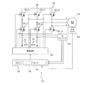
- FIG. 1 is a block diagram schematically showing a hardware block of a motor module 1000 of the present disclosure.
- FIG. 2 is a cross-sectional view of motor 700 taken along a plane perpendicular to the direction in which central axis J1 of rotation of rotor 920 extends.
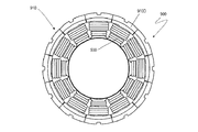
- FIG. 3 is a cross-sectional view of the stacked body 910 taken along a plane perpendicular to the direction in which the central axis J1 extends.
- FIG. 4 is a diagram schematically showing the split core 910D to which the winding wire 930 is attached.
- FIG. 5 is a plan view of a stator 900 having twelve split cores 910D each having a winding 930 attached thereto.
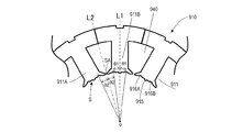
- FIG. 6 is an enlarged view of a part of the cross section of the stacked body 910 taken along a plane perpendicular to the direction in which the central axis J1 extends.
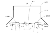
- FIG. 7 is an enlarged view showing the concavo-convex structure of the tip surfaces of the teeth 911 in the cross section of the laminated body 910.
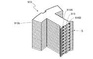
- FIG. 8 is a perspective view of the split core 910D.
- FIG. 9 is a perspective view of a variation of the split core 910D.
- FIG. 10 is a graph showing the analysis result of analyzing the effect of reducing the cogging torque.
- FIG. 11 is a graph showing an analysis result of analyzing the torque ripple reduction effect.
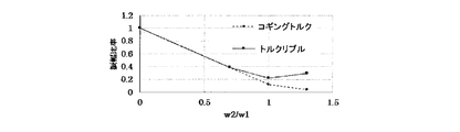
- FIG. 12 is a graph showing the measurement result of the ratio of torque amplitude.
- FIG. 13 is a graph showing the measurement result of the ratio of torque amplitude.
- FIG. 1 is a block diagram schematically showing a hardware block of the motor module 1000 of the present disclosure. ..
- the motor module 1000 is, in a non-limiting and exemplary embodiment, a motor control device 100, a drive circuit 200, an inverter 300, a current sensor 400, an analog-digital conversion circuit (hereinafter referred to as “AD converter”) 500, An angle sensor 600 and a motor 700 are provided.
- the motor module 1000 may be modularized and may be manufactured and sold, for example, as an electromechanical integrated motor including a motor, a sensor, a driver, and a motor controller. ..
- the motor 700 is, for example, a surface magnet type synchronous motor having three-phase windings (not shown) of U-phase, V-phase and W-phase.
- the three-phase winding is electrically connected to the inverter 300.
- the motor connection may be either Y connection or ⁇ connection.
- the structure of the motor 700 will be described in detail later. ..
- Motor controller 100 typically includes a processor 110 and a memory 120.
- the processor 110 can be, for example, an integrated circuit (IC) chip such as a digital signal processor (DSP) or a micro control unit (MCU).
- the processor 110 may be realized by, for example, a field programmable gate array (FPGA) in which a core of a central processing unit (CPU) is incorporated. ..
- the memory 120 includes, for example, a writable memory (for example, PROM), a rewritable memory (for example, flash memory) or a read-only memory, and a RAM (Random Access Memory).
- the memory 120 stores a control program having a command group for causing the motor control device 100 to control the motor 700.
- the control program is once expanded in the RAM (not shown) at the time of booting. ..
- the motor control device 100 controls the switching operation of the switch element included in the inverter 300. For example, the motor control device 100 sets a target current value according to a signal indicating the actual current value and the rotation angle of the rotor, generates a PWM (Pulse Width Modulation) signal, and outputs the PWM (Pulse Width Modulation) signal to the drive circuit 200. ..
- PWM Pulse Width Modulation
- the drive circuit 200 is typically a gate driver (or pre-driver).
- the drive circuit 200 generates a control signal for controlling the switching operation of the switch element included in the inverter 300 according to the PWM signal, and outputs the control signal to the inverter 300.
- the switch element of the inverter 300 is a MOS type field effect transistor (MOSFET).
- the control signal generated by the drive circuit 200 is a gate control signal given to the gate of the MOSFET. ..
- the inverter 300 is, for example, a half-bridge circuit, and has three low-side switch elements SW_L1, SW_L2, SW_L3, and three high-side switch elements SW_H1, SW_H2, and SW_H3.
- the switch element for example, a semiconductor switch element such as a MOSFET or an insulated gate bipolar transistor (IGBT) can be used.
- the inverter 300 converts, for example, DC power supplied from an external DC power supply (not shown) into AC power. Inverter 300 converts DC power into three-phase AC power that is a pseudo sine wave of U phase, V phase, and W phase. ..
- the current sensor 400 has at least two current sensors that detect at least two phase currents flowing in the U-phase, V-phase, and W-phase windings of the motor 700.
- FIG. 1 illustrates two current sensors 400A and 400B that detect currents flowing in the U phase and the V phase.
- Each of the current sensors 400A and 400B has, for example, a shunt resistor Rs and a current detection circuit (not shown) that detects a current flowing through the shunt resistor Rs. ..
- the AD converter 500 samples the analog signal output from the current sensor 400, converts it into a digital signal, and outputs the converted digital signal to the motor control device 100. ..
- the angle sensor 600 is, for example, a resolver or a Hall IC. Alternatively, the angle sensor 600 is also realized by a combination of an MR sensor having a magnetoresistive (MR) element and a sensor magnet. The angle sensor 600 detects the rotation angle of the rotor (referred to as “rotor angle”) and outputs it to the motor control device 100. ..
- the outer peripheral surface of the rotor faces the inner peripheral surface of the stator defined by the tip surfaces of the stator teeth via an air gap.
- the magnetic flux passing through the air gap mainly flows in the radial direction and the circumferential direction.
- a circumferential force (torque) and a radial force (radial force) are generated between the stator and the rotor. These forces are called "electromagnetic forces".
- the interlinking magnetic flux that generates the electromagnetic force includes the interlinking magnetic flux generated by the permanent magnet of the rotor and the interlinking magnetic flux formed by energizing the winding of the stator.
- Spatial harmonics The number of interlinkage magnetic fluxes formed by the magnetic poles of the rotor on the stator winding changes periodically according to the rotational position of the rotor.
- the rotation angle (or angular position) of the rotor will be represented by the angle ⁇ from the reference direction in the fixed coordinate system.
- the number of interlinkage magnetic fluxes formed in each stator winding when a current is passed through the stator winding also depends on the inductance that can periodically change according to the rotation angle ⁇ of the rotor.
- Each of the rotor magnetic poles and the inductance may include a non-negligible harmonic component (spatial harmonic component) other than the fundamental wave component having the rotor rotation angle ⁇ as a variable.
- Such spatial harmonic components cause ripples in the torque generated when a current is flowing through the stator winding. ..
- the cogging torque does not depend on the presence or absence of a current (driving current) in the stator winding. Therefore, when a current is passed through the stator winding to operate the motor (in a load state), a torque ripple in which a component due to a spatial harmonic and a component due to a cogging phenomenon overlap each other is generated. ..
- the present inventor has arrived at a surface magnet type motor capable of appropriately reducing the cogging torque and the torque ripple at the time of load while suppressing the decrease of the average torque of the motor. It was Hereinafter, the structure of the surface magnet type motor will be described in more detail. ..
- FIG. 2 is a cross-sectional view of the motor 700 taken along a plane perpendicular to the direction in which the central axis J1 of rotation of the rotor 920 extends.
- FIG. 3 is a sectional view of the laminated annular core 910 taken along a plane perpendicular to the direction in which the central axis J1 extends.
- FIG. 4 is a diagram schematically showing the split core 910D to which the winding wire 930 is attached.
- FIG. 5 is a plan view of a stator 900 having twelve split cores 910D each having a winding 930 attached thereto. ..
- the motor 700 includes a stator 900 and a rotor 920.
- the motor 700 is, in a non-limiting, exemplary embodiment, an 8 pole 12 slot surface magnet motor (SPM).
- the annular stator 900 has an annular laminate (sometimes referred to as “laminated annular core”) 910 and windings (sometimes referred to as “coils”) 930.
- FIG. 2 shows a winding 930 attached to only one split core 910D in order to avoid making the drawing complicated.
- the stator 900 generates magnetic flux according to the drive current.
- the laminated body 910 is formed of a laminated steel sheet in which a plurality of steel sheets (hereinafter referred to as “annular core sheets”) are laminated along a direction parallel to the central axis J1 of rotation of the rotor 920.
- the laminated body 910 may include an annular laminated core back 912 and M (M is an integer of 3 or more) laminated teeth (hereinafter, referred to as “teeth”) 911.
- FIG. 2 illustrates a laminated body 910 having twelve teeth 911. A slot 940 exists between two adjacent teeth 911. That is, the stack 910 has twelve slots 940.
- the laminated core back 912 is fixed to the inner wall of the motor housing (not shown). ..
- the tip surfaces of the twelve teeth 911 define the inner peripheral surface S of the stator 900 shown in FIG.
- the inner peripheral surface may be referred to as a front end surface and may be referred to as a front end surface S. ..
- the rotor 920 has a rotor core 921 and N (N is an integer of 2 or more) permanent magnets 922.
- the rotor 920 has an outer peripheral surface that faces the inner peripheral surface S of the stator 900 via an air gap 950.
- the N permanent magnets 922 are evenly arranged on the outer peripheral surface thereof.
- the permanent magnet 922 is fixed to the outer peripheral surface of the rotor core 921 while being supported by a magnet holder (not shown).
- FIG. 2 illustrates a rotor 920 having eight permanent magnets 922.
- the size of the air gap 950 is about 0.5 mm. ..
- the motor 700 is an 8-pole 12-slot SPM. ..
- the winding 930 is formed of a conductive wire (generally a copper wire), and is typically attached to each of the 12 teeth 911 included in the stack 910.
- the winding method of the stator winding may be concentrated winding or distributed winding. ..
- the stacked body 910 may be divided into 12 split cores 910D.
- the stacked body 910 is divided so that each split core 910D has one tooth 911.
- the winding 930 is attached to each of the 12 divided cores 910D.
- the annular stator 900 shown in FIG. 5 is obtained by returning the twelve split cores 910D, each having the winding 930 attached thereto, to the annular shape using a jig. ..
- the rotor core 921 and the magnet holder are integrated by insert molding.
- the eight permanent magnets 922 are fixed to the outer peripheral surface of the rotor 920.
- the rotor 920 is obtained. ..
- FIG. 6 is an enlarged view of a part of the cross section of the stacked body 910 taken along a plane perpendicular to the direction in which the central axis J1 extends.
- FIG. 7 is an enlarged view showing the concavo-convex structure of the tip surfaces of the teeth 911 in the cross section of the laminated body 910.
- FIG. 8 is a perspective view of the split core 910D. ..
- the tip surfaces of the teeth 911 have an uneven structure.
- the concavo-convex structure includes two grooves 916A and 916B arranged at intervals in the circumferential direction of the stator 900 or the inner peripheral surface S, and a ridge 915 located between the two grooves 916A and 916B.
- reference numerals 916A and 916B are given to the two grooves located on the tip surface S along the circumferential direction in the clockwise order.
- two teeth adjacent to each other in the laminated body 910 are denoted by reference numerals 911A and 911B in a clockwise order, respectively. ..
- a reference line (one-dot chain line in the figure) L1 and a reference plane R are defined.
- the reference line L1 is a straight line that passes through the center point o on the center axis J1 and divides the tooth 911 into two substantially equal parts in a plan view.
- the reference plane R means a plane including the openings A of the two grooves 916A and 916B.
- the reference surface R is a part of the inner peripheral surface S and includes a surface located between the ridge 915 and the groove 916A and a surface located between the ridge 915 and the groove 916B. ..
- the ridge 915 is a portion that projects relatively to the reference surface R
- each of the two grooves 916A and 916B is a portion that is recessed relative to the reference surface R. is there. ..
- the ridge 915 projects from the reference plane R toward the outer peripheral surface of the rotor 920.
- the ridge 915 extends in the direction parallel to the central axis J1 of the rotation of the rotor 920 on the tip surface S of the tooth 911.
- the ridge 915 divides the tip end surface S of the tooth 911 into two equal parts, and is located between the two grooves 916A and 916B.
- the ridge 915 is located on the reference line L1 in the cross section (hereinafter, referred to as “cross section C”) of the stacked body 910 taken along the plane perpendicular to the direction in which the central axis J1 extends.
- the height h1 of the ridge 915 from the reference plane R see FIG.
- the ridge 915 may be a column such as a square pole or a convex portion having a semi-cylindrical shape.
- the corner may have a minute roundness R. ..
- Each of the two grooves 916A and 916B is a recess dug in the tip surface S of the tooth 911.
- the two grooves 916A and 916B extend in a direction parallel to the central axis J1 together with the ridge 915.
- the two grooves 916A and 916B are located on the tip surface S in a substantially line symmetrical manner with respect to the ridge 915.
- the two grooves 916A and 916B typically have substantially the same shape.
- the corner of the groove may have a minute roundness R.
- the depth h2 (see FIG. 7) of each of the two grooves 916A and 916B from the reference plane R is, for example, about 0.1 mm. ..
- the distance between the groove 916A and the ridge 915 is equal to the distance between the groove 916B and the ridge 915. More specifically with reference to FIG. 6, in section C, the angle (that is, the center angle) formed by the line segment connecting the center of the groove 916A and the center point o and the reference line L1 is the center of the groove 916B. It is equal to the angle formed by the line segment connecting the point o and the reference line L1. The angle is ⁇ 1. ..
- the width w1 of the ridge in the circumferential direction of the inner peripheral surface S and the width w2 of each of the two grooves 916A and 916B satisfy the relationship of 0.5 ⁇ (w2 / w1) ⁇ 1.5. . The reason will be described later. ..
- the twelve teeth 911 included in the stacked body 910 include adjacent teeth 911A and teeth 911B. Slot openings SA are formed between the tip surfaces of the teeth 911A and the teeth 911B. The positions where the two grooves 916A and 916B are arranged on the inner peripheral surface S further satisfy the following conditions between the adjacent teeth 911A and teeth 911B. ..
- a line segment that connects the center of the slot opening SA and the center point o is called a first line segment.
- the first line segment corresponds to the reference line L2 (two-dot chain line shown in FIG. 6) that passes through the center of the slot opening SA and the center point o.
- a line segment that connects the center of the groove 916B on the slot opening SA side of the two grooves 916A and 916B arranged on the tip end surface of the tooth 911A and the center point o is called a second line segment. Similar to the second line segment, a line segment that connects the center of the groove 916A on the slot opening SA side of the two grooves 916A and 916B arranged on the tip end surface of the tooth 911B and the center point o is the third line segment. Call it a line segment. ..
- the angle (center angle) formed by the first line segment (or the reference line L2) and the second line segment is equal to the angle formed by the first line segment and the third line segment.
- the angle is ⁇ 2.
- the distance from the center of the slot opening SA to the center of the groove 916A is equal to the distance from the center of the slot opening SA to the center of the groove 916B.
- the angle ⁇ 2 preferably satisfies the relationship of 5.0 ° ⁇ 2 ⁇ 6.5 °. The reason will be described later. ..
- FIG. 9 is a perspective view of a variation of the split core 910D. ..
- the laminated body 910 is formed by laminating a plurality of annular core sheets. 8 and 9 illustrate one split core 910D included in the laminated body 910 in which 19 annular core sheets 910s are laminated.
- the number of stacked layers is not limited to this, and is appropriately determined depending on, for example, the required characteristics required for the motor. ..
- ridges and grooves in the present specification refers to not only ridges and grooves formed by continuously providing an uneven structure on all the laminated annular core sheets, but also some of the laminated annular core sheets. It also includes a ridge and a groove formed by discontinuously providing an uneven structure on the annular core sheet.
- FIG. 8 shows a concavo-convex structure including a ridge 915 and grooves 916A and 916B formed continuously on the tip surface S of the split core 910D.
- FIG. 9 shows a concavo-convex structure including a ridge 915 and grooves 916A and 916B formed discontinuously on the tip surface of the split core 910D.
- the laminated body 910 is obtained by alternately laminating the annular core sheet 910s having the convex portions forming the ridge 915 and the concave portions forming the grooves 916A and 916B and the annular core sheet 910s having no convex portion and the concave portion. Can be formed. ..
- the discontinuous concavo-convex structure shown on the tip surface S of the split core 910D shown in FIG. 9 is in the category of the concavo-convex structure including the ridge and the groove of the present disclosure. Further, for example, a concavo-convex structure having a ridge continuously formed on the tip surface S of the split core 910D and a groove formed discontinuously, a ridge discontinuously formed on the tip surface of the split core 910D, and a groove formed continuously. Concavo-convex structures with or other irregular concavo-convex structures are also within the scope of the present disclosure. ..
- the uneven ridge 915 is used to generate the antiphase cogging torque
- the two grooves 916A and 916B of the uneven structure are used to generate the antiphase torque ripple.
- the width w1 of the ridge 915 is set to an optimum value for the cogging torque
- the width w2 of each of the two grooves 916A and 916B is set to the optimum value for the torque ripple.
- the result of examining the optimum range (range of the angle ⁇ 2) of the positions where the grooves 916A and 916B are arranged will be described. ..
- the resultant electromagnetic force of the cogging torque and the torque ripple in the circumferential direction is obtained by angularly integrating the square of the magnetic flux density B g ( ⁇ , ⁇ t) in the air gap, and is represented by the following formula 1. .
- the magnetic flux density B g ( ⁇ , ⁇ t) is represented by the product of the magnetomotive force F ( ⁇ , ⁇ t) and the permeance ⁇ ( ⁇ ) shown in the following formula (2).
- the magnetomotive force F ( ⁇ , ⁇ t) is assumed to have a magnetomotive force component Fr_rt ( ⁇ , ⁇ t) on the rotor side and a magnetomotive force component Fr_st ( ⁇ , ⁇ t) on the stator side.
- the magnetomotive force F ( ⁇ , ⁇ t) is the resultant force of those components and is represented by the following formula (3).
- the stator-side magnetomotive force Fr_st ( ⁇ , ⁇ t) in the equation (3) is the combined magnetomotive force of the U, V, and W phases.
- Permeance ⁇ ( ⁇ ) represents a combined permeance through the air gap between the rotor and the stator, and is represented by the following formula (4).
- the number m of concavities and convexities is m ⁇ 0.
- the number m of the unevenness means the number of one of the groove and the ridge included in the uneven structure.
- the main component of the cogging torque T cog is the torque ripple of the harmonic component of the order determined by the least common multiple of the number of poles (2 * Pn) and the number of slots s per one rotation of the rotor. From the equation (5), the 24th harmonic component having a frequency that is 24 times the fundamental wave component of the torque becomes the main component of the cogging torque T cog .
- Equations 5 and 6 are compared.
- the cogging torque T cog can be regarded as approximately 0.
- the cogging torque T cog can be made approximately zero by providing irregularities (specifically, ridges) having an appropriate size and an integral multiple of the number of slots s at appropriate positions on the tip surface. In that case, the permeance condition according to the value of m is satisfied as in the equations (6) and (7).
- Equations 9 and 10 are compared.
- the torque ripple converges to the value shown in the following formula (11).
- the textured structure according to embodiments of the present disclosure includes a ridge and two grooves. By providing the ridge and the two grooves on the tip end surface, it is possible to obtain a combined effect of reducing both the cogging torque and the torque ripple under load.
- the concavo-convex structure of the present disclosure not only the cogging torque but also the torque ripple can be obtained by providing the concavities and convexities having the appropriate size and including the ridges and the grooves, which are the integral multiples of the number of slots s, at the appropriate positions on the tip surface. Can be reduced at the same time. In that case, the condition of permeance according to the value of m is satisfied as in the equations (6), (7) or (10). This holds when the main vibration orders of the cogging torque and the torque ripple are equal, as in the case of a motor with 8 poles and 12 slots. ..
- An 8-pole 12-slot SPM700 according to an embodiment of the present disclosure having a concavo-convex structure including a ridge 915 and two grooves 916A and 916B on the tooth tip surface S is subjected to finite element simulation analysis of cogging torque and torque ripple. Method was used.
- the ridge 915 included in the concavo-convex structure on the tip surface generates antiphase cogging torque
- the two grooves 916A and 916B included in the concavo-convex structure generate antiphase torque ripple.
- the effect of reducing cogging torque and torque ripple was measured. ..
- FIG. 10 is a graph showing a simulation analysis result in which the effect of reducing the cogging torque is analyzed.
- FIG. 11 is a graph showing a simulation analysis result in which the effect of reducing the torque ripple is analyzed.
- the horizontal axis represents the motor mechanical angle ⁇ t [deg] and the vertical axis represents the torque amplitude ratio.
- 10 and 11 show the results of simulation analysis of torque in the case where the concavo-convex structure is not provided on the tip surface as a comparative example. From the measurement results, it is found that the cogging torque and the torque ripple can be effectively reduced by providing the concavo-convex structure on the tip surface. ..
- the widths of the ridge and the groove required by the uneven structure according to the present disclosure were specifically examined. ..
- the tip end surface S of the tooth 911 has an uneven structure including a ridge 915 and two grooves 916A and 916B.
- the depth h2 of each of the two grooves 916A and 916B is deeply related to the average torque. If the groove is deep, the average torque decreases. Therefore, the depth h2 of the groove is set to 0.1 [mm].
- the ridge 915 it is possible to reduce the relative groove depth h2 from the reference plane R. As a result, a decrease in average torque can be suppressed. ..
- the height h1 of the ridge 915 is set to 0.1 [mm] in consideration of contact with the rotor 920.
- the optimum value of the width w2 of each of the two grooves 916A and 916B was measured with respect to the width w1 of the ridge 915.
- FIG. 12 is a graph showing the measurement result of the ratio of torque amplitude.
- the horizontal axis represents the ratio w2 / w1 of the width w2 to the width w1
- the vertical axis represents the torque amplitude ratio.
- the graph shows the measurement results of the amplitude ratio of cogging torque and torque ripple.
- the range of the groove width w2 in which both the amplitude ratios of both the cogging torque and the torque ripple are 0.5 or less is 0.5 * w1 ⁇ w2 ⁇ 1.5 * w1. Therefore, as compared with the case where no groove is provided, both the cogging torque and the torque ripple can be reduced to half or less by setting the width w2 of the two grooves to an appropriate value within the range. ..
- the width w2 of each of the two grooves 916A and 916B was fixed, and the optimum position for arranging the grooves on the tip surface S was measured.
- the change in the amplitude ratio of the torque when the angle ⁇ 2 was swung with respect to the reference value was measured. ..
- FIG. 13 is a graph showing the measurement result of the ratio of torque amplitude.
- the horizontal axis in the graph represents the value of the groove angle ⁇ 2 shown in FIG. 6, and the vertical axis represents the torque amplitude ratio.
- the graph shows the measurement results of the amplitude ratio of cogging torque and torque ripple.
- the range of the angle ⁇ 2 where the amplitude ratios of both the cogging torque and the torque ripple are 0.5 or less is 5.0 ° ⁇ 2 ⁇ 6.5 °. Therefore, by arranging the two grooves within the range, both the cogging torque and the torque ripple can be reduced to half or less.
- the embodiments of the present disclosure can be widely used in various motors used in vacuum cleaners, dryers, ceiling fans, washing machines, refrigerators, electric power steering devices, and the like.
- stator 910: laminated body, 911: teeth, 915: ridge, 916A, 916B: groove, 920: rotor, 930: winding, 940: slot
Landscapes
- Engineering & Computer Science (AREA)
- Power Engineering (AREA)
- Iron Core Of Rotating Electric Machines (AREA)
- Permanent Magnet Type Synchronous Machine (AREA)
Abstract
本開示の表面磁石型モータは、M個(Mは3以上の整数)のティース(911)を有する環状のステータ(900)と、M個のティースの先端面が規定するステータの内周面(S)にエアギャップ(950)を介して対向する外周面を有するロータ(920)であって、N個(Nは2以上の整数)の永久磁石(922)を外周面に有するロータと、を備える。M個のティースの先端面のそれぞれは、ステータの周方向に間隔を空けて配置された2本の溝(916A、916B)、および、2本の溝の間に位置するリッジ(915)を含む凹凸構造を有する。2本の溝およびリッジは、ロータ(920)の回転の中心軸(J1)に平行な方向に延びている。
Description
本願は、表面磁石型モータおよびモータモジュールに関している。
モータ構造を工夫してコギングトルクおよび負荷時のトルクリップルの両方を低減するための手法が提案されている。特開2001-339921号公報は、複数の補助溝をステータティースの先端面に設け、かつ、ロータとステータの間に電気角72°に相当するスキューを与えることにより、誘起電圧の高調波を低減する技術を開示している。特開2003-61272号公報は、隣接する2つのティースの間に位置するスロットにおいて生じるパーミアンスの変動と略等価なパーミアンスの変動を生じさせる複数の補助溝を先端面に設ける技術を開示している。
コギングトルクおよび負荷時のトルクリップルを一層低減することが求められている。
本開示の表面磁石型モータは、例示的な実施形態において、M個(Mは3以上の整数)のティースを有する環状のステータと、前記M個のティースの先端面が規定する前記ステータの内周面にエアギャップを介して対向する外周面を有するロータであって、N個(Nは2以上の整数)の永久磁石を前記外周面に有するロータと、を備え、前記M個のティースの先端面のそれぞれは、前記ステータの周方向に間隔を空けて配置された2本の溝、および、前記2本の溝の間に位置するリッジを含む凹凸構造を有し、前記2本の溝および前記リッジは、前記ロータの回転の中心軸に平行な方向に延びている。
本開示の実施形態は、モータの平均トルクの低下を抑制しつつ、コギングトルクおよび負荷時のトルクリップルの両方を適切に低減することが可能となる新規な表面磁石型モータおよび当該表面磁石型モータを備えるモータモジュールを提供する。
以下、添付の図面を参照しながら、本開示の表面磁石型モータおよびモータモジュールの実施形態を詳細に説明する。但し、必要以上に詳細な説明は省略する場合がある。例えば、既によく知られた事項の詳細説明や実質的に同一の構成に対する重複説明を省略する場合がある。これは、以下の説明が不必要に冗長になるのを避け、当業者の理解を容易にするためである。
〔1.モータモジュール1000〕 図1は、本開示のモータモジュール1000のハードウェアブロックを模式的に示すブロック図である。
モータモジュール1000は、非限定的で例示的な実施形態において、モータ制御装置100、駆動回路200、インバータ300、電流センサ400、アナログデジタル変換回路(以下、「ADコンバータ」と表記する。)500、角度センサ600およびモータ700を備える。モータモジュール1000は、モジュール化され得て、例えば、モータ、センサ、ドライバおよびモータ制御装置を備える機電一体型モータとして製造および販売され得る。
モータ700は、例えばU相、V相およびW相の三相の巻線(不図示)を有する表面磁石型同期モータである。三相の巻線は、インバータ300に電気的に接続される。モータの結線は、Y結線およびΔ結線のいずれであって構わない。モータ700の構造は、後で詳しく説明する。
モータ制御装置100は、典型的にはプロセッサ110およびメモリ120を有する。プロセッサ110は、例えば、デジタル信号処理プロセッサ(DSP)またはマイクロコントロールユニット(MCU)などの集積回路(IC)チップであり得る。または、プロセッサ110は、例えば、中央演算処理装置(CPU)のコアが組み込まれたフィールドプログラマブルゲートアレイ(FPGA)によっても実現され得る。
メモリ120は、例えば書き込み可能なメモリ(例えばPROM)、書き換え可能なメモリ(例えばフラッシュメモリ)または読み出し専用のメモリ、およびRAM(Random Access Memory)を含む。メモリ120は、モータ制御装置100にモータ700を制御させるための命令群を有する制御プログラムを格納する。例えば、制御プログラムはブート時にRAM(不図示)に一旦展開される。
モータ制御装置100は、インバータ300が有するスイッチ素子のスイッチング動作を制御する。例えば、モータ制御装置100は、実電流値およびロータの回転角を示す信号などに従って目標電流値を設定してPWM(Pulse Width Modulation)信号を生成し、駆動回路200に出力する。
駆動回路200は、典型的にはゲートドライバ(またはプリドライバ)である。駆動回路200は、インバータ300が有するスイッチ素子のスイッチング動作を制御する制御信号をPWM信号に従って生成し、インバータ300に出力する。後述するとおり、例えば、インバータ300のスイッチ素子は、MOS型の電界効果トランジスタ(MOSFET)である。駆動回路200が生成する制御信号は、MOSFETのゲートに与えるゲート制御信号である。
インバータ300は、例えばハーフブリッジ回路であり、3個のローサイドスイッチ素子SW_L1、SW_L2、SW_L3、3個のハイサイドスイッチ素子SW_H1、SW_H2およびSW_H3を有する。スイッチ素子に、例えば、MOSFETまたは絶縁ゲートバイポーラトランジスタ(IGBT)などの半導体スイッチ素子を用いることができる。インバータ300は、例えば、外部の直流電源(不図示)から供給される直流電力を交流電力に変換する。インバータ300は、直流電力を、U相、V相およびW相の擬似正弦波である三相交流電力に変換する。
電流センサ400は、モータ700のU相、V相およびW相の巻線に流れる少なくとも2つの相電流を検出する少なくとも2つの電流センサを有する。図1に、U相およびV相に流れる電流を検出する2つの電流センサ400A、400Bを例示する。電流センサ400A、400Bのそれぞれは、例えば、シャント抵抗Rs、およびシャント抵抗Rsに流れる電流を検出する電流検出回路(不図示)を有する。
ADコンバータ500は、電流センサ400から出力されるアナログ信号をサンプリングしてデジタル信号に変換し、その変換したデジタル信号をモータ制御装置100に出力する。
角度センサ600は、例えばレゾルバまたはホールICである。または、角度センサ600は、磁気抵抗(MR)素子を有するMRセンサとセンサマグネットとの組み合わせによっても実現される。角度センサ600は、ロータの回転角(「ロータ角」と呼ばれる。)を検出してモータ制御装置100に出力する。
ロータおよびステータを備える表面磁石型モータ内において、ロータの外周面は、ステータティースの先端面が規定するステータ内周面にエアギャップを介して対向している。エアギャップを通る磁束は、主にラジアル方向と周方向に流れる。その結果、ステータとロータとの間には、周方向の力(トルク)とラジアル方向の力(ラジアル力)とが発生する。これらの力は「電磁力」と称されている。電磁力を生成する鎖交磁束は、ロータの永久磁石による鎖交磁束と、ステータの巻線に通電して形成される鎖交磁束とを含む。各ティースを貫通する磁束成分(鎖交磁束)の大きさは、空間的および時間的に変化するため、電磁力も空間的および時間的に変化する。これがトルクリップルの原因になる。一般に、トルクリップルの原因は大きく以下の2種類に分けられる。
(1)空間高調波 ロータの磁極がステータ巻線に形成する鎖交磁束数は、ロータの回転位置に応じて周期的に変化する。以下、ロータの回転角(または角度位置)を、固定座標系における基準方向からの角度θによって表す。ステータ巻線に電流を流したときに各ステータ巻線に形成される鎖交磁束数も、ロータの回転角θに応じて周期的に変化し得るインダクタンスに依存する。ロータの磁極およびインダクタンスのそれぞれは、ロータの回転角θを変数とする基本波成分以外に無視できない高調波成分(空間高調波成分)を含む場合がある。このような空間高調波成分は、ステータ巻線に電流を流しているときに生じるトルクにリプルを引き起こす。
(2)コギングトルク ステータ巻線に電流を流していない状態(無負荷状態)でも、ロータとステータの間にあるエアギャップには、ロータの磁極による磁束が存在し、磁気エネルギが蓄積される。このエアギャップは、ステータが有する複数のスロットの存在により、ロータの回転角θに応じて周期的に変化するため、磁気エネルギはロータの回転角θの関数である。ステータ巻線に電流が流れていない状態でエアギャップに蓄積される磁気エネルギをW(θ)とするとき、δW(θ)/δθで表される大きさのトルクが発生する。これを「コギングトルク」と称する。コギングトルクは、ステータ巻線の電流(駆動電流)の有無に依存しない。このため、ステータ巻線に電流を流してモータを動作(負荷状態)させると、空間高調波に起因する成分とコギング現象に起因する成分とが重なったトルクリップルが発生する。
本発明者の検討によると、ステータティースの先端面に溝を設けた場合、通常、モータの平均トルクが低下する。溝の本数が増えるほど、モータ通電時の負荷状態において磁束の空間高調波は高周波化する。そのため、低い時間周波数の振動を打ち消すパーミアンスの変動を生じさせることが困難となる。
本発明者は、上記の知見に基づいて、モータの平均トルクの低下を抑制しつつ、コギングトルクおよび負荷時のトルクリップルを適切に低減することが可能となる表面磁石型モータに想到するに至った。以下、表面磁石型モータの構造をより詳しく説明する。
〔2.モータ700の構造〕 図2は、ロータ920の回転の中心軸J1が延びる方向に垂直な面に沿って切断したモータ700の断面図である。図3は、中心軸J1が延びる方向に垂直な面に沿って切断した積層環状コア910の断面図である。図4は、巻線930を取り付けた分割コア910Dを模式的に示す図である。図5は、それぞれに巻線930を取り付けた12個の分割コア910Dを有するステータ900の平面図である。
モータ700は、ステータ900およ
びロータ920を備える。モータ700は、非限定的で例示的な実施形態において、8極12スロットの表面磁石型モータ(SPM)である。
びロータ920を備える。モータ700は、非限定的で例示的な実施形態において、8極12スロットの表面磁石型モータ(SPM)である。
環状のステータ900は、環状の積層体(「積層環状コア」と表記する場合がある。)910および巻線(「コイル」と称される場合がある。)930を有する。図2には、図面が煩雑になることを避けるため、1個の分割コア910Dだけに取り付けた巻線930を図示している。ステータ900は、駆動電流に応じて磁束を発生させる。積層体910は、ロータ920の回転の中心軸J1に平行な方向に沿って複数の鋼板(「環状コアシート」と呼ぶこととする。)を積層した積層鋼板から形成される。積層体910は、環状の積層コアバック912およびM個(Mは3以上の整数)の積層歯(以降、「ティース」と表記する。)911を含み得る。図2に、12個のティース911を有する積層体910を例示する。隣接する2つのティース911の間にスロット940が存在する。つまり、積層体910は、12個のスロット940を有する。積層コアバック912は、モータのハウジング(不図示)の内壁に固定される。
12個のティース911の個々の先端面によって、図3に示すステータ900の内周面Sを規定する。以降、内周面を先端面と呼び、先端面Sと表記する場合がある。
ロータ920は、ロータコア921およびN個(Nは2以上の整数)の永久磁石922を有する。ロータ920は、ステータ900の内周面Sにエアギャップ950を介して対向する外周面を有する。N個の永久磁石922は、その外周面に均等に配置されている。例えば、永久磁石922はマグネットホルダ(不図示)に支持された状態でロータコア921の外周面に固定される。図2に、8個の永久磁石922を有するロータ920を例示する。例えば、エアギャップ950の大きさは、0.5mm程度である。
表面磁石型モータであるモータ700における永久磁石922の数Nと、ティース911(またはスロット940)の数Mとの比は、N:M=2:3であり得る。本開示の実施形態では、モータ700は8極12スロットのSPMである。
巻線930は、導線(一般的には銅線)によって形成され、典型的には、積層体910が有する12個のティース911のそれぞれに取り付けられる。ステータ巻線の巻き方は、集中巻であってもよく、分布巻であってもよい。
ステータ900およびロータ920の製造方法の一例を簡単に説明する。例えば、製造時において、積層体910は、12個の分割コア910Dに分割され得る。集中巻の場合、原則、それぞれの分割コア910Dが1個のティース911を有するように積層体910を分割する。積層体910を分割した後、図4に示すように、12個の分割コア910Dのそれぞれに巻線930を取り付ける。各々に巻線930を取り付けた12個の分割コア910Dを、治具を用いて環状に戻すことにより、図5に示す環状のステータ900が得られる。
例えば、インサート成形によってロータコア921とマグネットホルダ(不図示)とを一体化する。一体化したロータコア921およびマグネットホルダに永久磁石922を挿入することにより、8個の永久磁石922をロータ920の外周面に固定する。これによりロータ920が得られる。
図6は、中心軸J1が延びる方向に垂直な面に沿って切断した積層体910の断面の一部を拡大した図である。図7は、積層体910の断面におけるティース911の先端面の凹凸構造を拡大して示す図である。図8は、分割コア910Dの斜視図である。
ティース911の先端面は、凹凸構造を有している。凹凸構造は、ステータ900または内周面Sの周方向に間隔を空けて配置された2本の溝916A、916B、および、2本の溝916A、916Bの間に位置するリッジ915を含む。図面において、周方向に沿って先端面Sに位置する2本の溝に、時計回りの順番で参照符号916A、916Bを付している。これと同様に、積層体910において隣接する2個のティースに、時計回りの順番で参照符号911A、911Bをそれぞれ付している。
基準線(図中の一点鎖線)L1および基準面Rを定義する。基準線L1は、中心軸J1上の中心点oを通り、かつ、平面視においてティース911を略二等分する直線である。基準面Rは、2本の溝916A、916Bのそれぞれの開口Aを含む面を意味する。基準面Rは、内周面Sの一部であり、リッジ915と溝916Aの間に位置する面およびリッジ915と溝916Bの間に位置する面を含む。
先端面Sが有する凹凸構造において、リッジ915は、基準面Rに対し相対的に突出した部分であり、2本の溝916A、916Bのそれぞれは、基準面Rに対し相対的に窪んだ部分である。
リッジ915は、基準面Rからロータ920の外周面に向けて突出している。リッジ915は、ティース911の先端面Sにおいて、ロータ920の回転の中心軸J1に平行な方向に延びている。リッジ915は、ティース911の先端面Sを二等分し、かつ、2本の溝916A、916Bの間に位置する。中心軸J1が延びる方向に垂直な面に沿って切断した積層体910の断面(以下、「断面C」と表記する。)において、リッジ915は基準線L1上に位置している。基準面Rからのリッジ915の高さh1(図7を参照)は、例えば0.1mm程度である。例えば、リッジ915は、四角柱などの柱体または半円柱状の形状を有する凸部であり得る。リッジ915の形状が柱体である場合において、角は微小の丸みRを有していてもよい。
2本の溝916A、916Bのそれぞれは、ティース911の先端面Sに掘られた凹部である。2本の溝916A、916Bは、リッジ915と共に、中心軸J1に平行な方向に延びている。2本の溝916A、916Bは、先端面Sにおいてリッジ915を基準に略線対称に位置している。2本の溝916A、916Bは、典型的には略同一の形状を有する。溝の隅は、微小の丸みRを有していてもよい。2本の溝916A、916Bのそれぞれの、基準面Rからの深さh2(図7を参照)は、例えば0.1mm程度である。
内周面Sの周方向において、溝916Aとリッジ915の間の距離は、溝916Bとリッジ915の間の距離に等しい。図6を参照してより詳しく説明すると、断面Cにおいて、溝916Aの中心と中心点oとを結ぶ線分と、基準線L1とがなす角度(つまり中心角)は、溝916Bの中心と中心点oとを結ぶ線分と、基準線L1とがなす角度に等しい。その角度はθ1である。
内周面Sの周方向におけるリッジの幅w1と、2本の溝916A、916Bの各々の幅w2とは、0.5<(w2/w1)<1.5の関係を満足することが好ましい。理由は後述する。
積層体910が有する12個のティース911は、隣接するティース911Aおよびティース911Bを含む。ティース911Aおよびティース911Bの先端面の間にスロット開口SAが形成される。内周面Sにおいて2本の溝916A、916Bが配置される位置は、隣接するティース911Aおよびティース911Bの間で以下の条件をさらに満足する。
スロット開口SAの中心と中心点oとを結ぶ線分を第1の線分と呼ぶ。第1の線分は、スロット開口SAの中心および中心点oを貫く基準線L2(図6に示す2点鎖線)に相当する。ティース911Aの先端面に配置された2本の溝916A、916Bのうちのスロット開口SA側の溝916Bの中心と中心点oとを結ぶ線分を第2の線分と呼ぶ。第2の線分と同様に、ティース911Bの先端面に配置された2本の溝916A、916Bのうちのスロット開口SA側の溝916Aの中心と中心点oとを結ぶ線分を第3の線分と呼ぶ。
第1の線分(または基準線L2)と第2の線分とがなす角度(中心角)は、第1の線分と第3の線分とがなす角度に等しい。その角度はθ2である。換言すると、内周面Sの周方向において、スロット開口SAの中心から溝916Aの中心までの距離は、スロット開口SAの中心から溝916Bの中心までの距離に等しい。角度θ2は、5.0°<θ2<6.5°の関係を満足することが好ましい。理由は後述する。
図9は、分割コア910Dのバリエーションの斜視図である。
既に説明したとおり、複数の環状コアシートを積層することにより、積層体910は形成される。図8および図9には、19枚の環状コアシート910sを積層した積層体910が有する1個の分割コア910Dを例示する。ただし、積層枚数はこれに限定されず、例えばモータに要求される必要特性に応じて適宜決定される。
本明細書中のリッジおよび溝という用語は、積層した全ての環状コアシートに凹凸構造を連続的に設けることにより形成されるリッジおよび溝のみならず、積層した環状コアシートのうちの幾つかの環状コアシートに凹凸構造を不連続に設けることにより形成されるリッジおよび溝も含む。図8には、分割コア910Dの先端面Sに連続的に形成したリッジ915、溝916Aおよび916Bを含む凹凸構造を示す。図9には、分割コア910Dの先端面に不連続に形成したリッジ915、溝916Aおよび916Bを含む凹凸構造を示す。例えば、リッジ915を形成する凸部および溝916A、916Bを形成する凹部を有する環状コアシート910sと、凸部および凹部を有しない環状コアシート910sと、を交互に積層することにより積層体910は形成され得る。
図9に示す分割コア910Dの先端面Sに表す不連続な凹凸構造は、本開示のリッジおよび溝を含む凹凸構造の範疇である。さらに、例えば、分割コア910Dの先端面Sに連続的に形成したリッジおよび不連続に形成した溝を有する凹凸構造、分割コア910Dの先端面に不連続に形成したリッジおよび連続的に形成した溝を有する凹凸構造または他の不規則な凹凸構造もまた、本開示の範疇である。
本開示の実施形態では、逆位相のコギングトルクを生じさせるために、凹凸構造のリッジ915を用い、逆位相のトルクリップルを生じさせるために、凹凸構造の2本の溝916A、916Bを用いる。リッジ915の幅w1をコギングトルクに対し最適な値に設定し、2本の溝916A、916Bのぞれぞれの幅w2をトルクリップルに対し最適な値に設定する。凹凸構造における幅w1、w2を調整することにより、モータの平均トルクの低下を抑制しつつ、コギングトルクおよび負荷時のトルクリップルの両方を適切に低減させることが可能となる コギングトルクおよび負荷時のトルクリップルの低減効果を説明するために、コギングトルクの近似式を導出する。その近似式を用いて、リッジ915の幅w1に対する2本の溝916A、916Bのぞれぞれの幅w2の比率(w2/w1)の最適な範囲、およびティース911の先端面Sにおいて2本の溝916A、916Bを配置する位置の最適な範囲(角度θ2の範囲)を検討した結果を説明する。
コギングトルクの近似式を導出する前に、その近似式に用いる各記号を定義しておく。機械角:θ〔rad〕、機械角速度:ω〔rad/s〕、時間:t[s]、ロータ側の起磁力k次成分の振幅:Frt_k、ステータ側の起磁力l次成分の振幅:Fst_l、極対数:Pn、相電流振幅:I、電流進角:β、パーミアンス平均値:Λ0、パーミアンスs,m次成分の振幅:Λs,Λm、パーミアンスs,m次成分の位相:θs,θm、スロット数:s、凹凸の数:m。
コギングトルクおよびトルクリップルの周方向の電磁力の合力は、エアギャップ中の磁束密度Bg(θ,ωt)の2乗を角度積分することによって得られ、以下の数1の式で表される。磁束密度Bg(θ,ωt)を、以下の数2の式に示す起磁力F(θ,ωt)とパーミアンス
Λ(θ)との積で表す。


Λ(θ)との積で表す。
起磁力F(θ,ωt)は、ロータ側の起磁力の成分Fr_rt(θ,ωt)およびステータ側の起磁力の成分Fr_st(θ,ωt)を有しているとする。起磁力F(θ,ωt)は、それらの成分の合力であり、以下の数3の式で表される。数3の式におけるステータ側の起磁力Fr_st(θ,ωt)は、U、VおよびW相の合成起磁力である。パーミアンスΛ(θ)は、ロータとステータの間のエアギャップを介した合成パーミアンスを示し、以下の数4の式で表される。


ティースの先端面に凹凸構造を設けた場合、凹凸の数mはm≠0である。凹凸の数mは、凹凸構造が含む溝およびリッジの一方の数を意味する。例えば、8極12スロットのモータの場合、m=12は、凹凸構造のリッジだけの数を指し、m=24は、凹凸構造が有する溝だけの数を指す。
〔3.無負荷状態におけるコギングトルクの近似式〕 ティースの先端面が凹凸構造を有しない場合における8極12スロットの集中巻モータについてのコギングトルクTcogの近似式を導出する。Pn(極対数)=4、s(スロット数)=12、m=0(凹凸の数m)を数3の式に代入する。無負荷時は、相電流振幅をI=0として扱うため、コギングトルクTcogの近似式として以下の数5の式が得られる。コギングトルクTcogの主成分は、ロータ一回転あたりにおける極数(2*Pn)およびスロット数sの最小公倍数よって決定される次数の高調波成分のトルクリップルである。数5の式から、トルクの基本波成分の24倍の振動数を有する24次高調波成分がコギングトルクTcogの主成分となる。

次に、ティースの先端面に凹凸構造を設けることにより、コギングトルクTcogを最小にすることを考える。m=12である場合、コギングトルクTcogの近似式として以下の数6が得られる。m=12は、1本のリッジを含む凹凸構造を意味する。

数5と数6の式を比較する。数6の式においてΛs=Λmおよびθs=θm+πの条件を満たす場合、コギングトルクTcogは、数5の式においてΛs=0とした場合と等しくなる。その結果、コギングトルクTcogは、近似的に0と見做せる。
m=24である場合、コギングトルクTcogの近似式として以下の数7の式が得られる。m=24は、2本のリッジを含む凹凸構造を意味する。数7の式において4Λs=Λ0Λmおよび2θs+π/2=θmの条件を満たす場合、コギングトルクTcogは、数5の式においてΛs=0とした場合と等しくなる。その結果、数7の式に示すコギングトルクTcogは、近似的に0と見做せる。

m=36、48、・・・と拡張した場合においても、m=12、24の場合と同様に、コギングトルクTcogは、近似的に0となることが推測される。適切なサイズを有する、スロット数sの整数倍の数の凹凸(具体的にはリッジ)を先端面の適切な位置に設けることによって、コギングトルクTcogを近似的に0にすることができる。その場合において、数6、数7の式のようにmの値に応じたパーミアンスの条件が満足される。
〔4.負荷状態におけるトルクの近似式〕 無負荷時と同様に、8極12スロットの集中巻モータの場合を考える。ステータ側の起磁力の成分Fr_st(θ,ωt)である数2の式における第2項は、以下の数8の式によって表される。さらに、負荷時のトルクの近似式は、数8の式に基づいて、相電流振幅Iを含む以下の数9の式によって表される。コギングトルクTcogと同様に、数9の式から、トルクの基本波成分の24倍の振動数を有する24次高調波成分がトルクの主成分となる。


次に、ステータティースの先端面に凹凸構造を設けることにより、トルクリップルを最小にすることを考える。m=12である場合、トルクの近似式として以下の数10の式が得られる。m=12は、1本の溝を含む凹凸構造を意味する。

数9と数10の式を比較する。数10の式においてΛs=Λmおよびθs=θm+πを満たす場合、トルクは、数9の式においてΛs=0とした場合と等しくなる。その結果、トルクリップルは以下の数11の式に示す値に収束する。

m=24の場合におけるトルクの近似式の説明は省略するが、m=12の場合と同様に、トルクリプルは、数11の式に示す値に収束することが推測される。
1本のリッジを先端面に設けることにより、コギングトルクTcogを近似的に0にすることができる(m=12に相当)。その結果、コギングトルクは効果的に低減される。また、2本の溝を先端面に設けることにより、トルクリプルは、数11の式に示す値に収束する(m=24に相当)。その結果、トルクリップルは効果的に低減される。本開示の実施形態による凹凸構造は、リッジおよび2本の溝を含む。リッジおよび2本の溝を先端面に設けることにより、コギングトルクおよび負荷時のトルクリップルの両方を低減できるという複合的な効果が得られる。
本開示の凹凸構造によれば、適切なサイズを有する、スロット数sの整数倍の数のリッジおよび溝を含む凹凸を先端面の適切な位置に設けることによって、コギングトルクのみならず、トルクリップルも同時に低減できる。その場合において、数6、数7または数10の式のようにmの値に応じたパーミアンスの条件が満足される。これは、8極12スロットのモータように、コギングトルクとトルクリップルとの主要な振動次数が等しくなる場合に成立する。
〔5.実施例〕 リッジ915および2本の溝916A,916Bを含む凹凸構造をティース先端面Sに有する、本開示の実施形態による8極12スロットのSPM700について、コギングトルクおよびトルクリップルのシミュレーション解析を有限要素法を用いて行った。先端面の凹凸構造が含むリッジ915によって逆位相のコギングトルクを発生させ、かつ、凹凸構造が含む2本の溝916A,916Bによって逆位相のトルクリップルを発生させる。これにより、コギングトルクおよびトルクリップルの低減効果を測定した。
図10は、コギングトルクの低減効果を解析したシミュレーション解析結果を示すグラフである。図11は、トルクリップルの低減効果を解析したシミュレーション解析結果を示すグラフである。図10、11において、横軸はモータ機械角ωt〔deg〕を示し、縦軸はトルクの振幅比を示す。図10、11に、凹凸構造を先端面に設けない場合のトルクのシミュレーション解析結果を比較例として示す。測定結果から、凹凸構造を先端面に設けることにより、コギングトルクおよびトルクリップルを効果的に低減できていることが分かる。
さらに、コギングトルクおよびトルクリップルを適切に低減するために、本開示による凹凸構造が必要とするリッジおよび溝の幅を具体的に検討した。
再び、図7を参照する。ティース911の先端面Sは、リッジ915、2本の溝916Aおよび916Bを含む凹凸構造を有する。2本の溝916A、916Bのそれぞれの深さh2は、平均トルクに深く関係する。溝が深いと、平均トルクは減少する。そのため、溝の深さh2を0.1〔mm〕とした。このように、リッジ915を設けることにより、基準面Rからの相対的な溝の深さh2を小さくすることが可能となる。その結果、平均トルクの低下を抑制することができる。
リッジ915の高さh1は、ロータ920との接触を懸念して、0.1〔mm〕とした。リッジ915の幅w1に対して2本の溝916A、916Bのぞれぞれの幅w2の最適な値を測定した。先端面Sにおける2本の溝916A、916Bの位置は固定し、2本の溝を設けない場合、つまり、w2=0の場合のトルクの振幅を基準値としてトルクの振幅の比率を測定した。
図12は、トルクの振幅の比率の測定結果を示すグラフである。図12のグラフにおける横軸は幅w1に対する幅w2の比率w2/w1を示し、縦軸はトルクの振幅比率を示す。グラフに、コギングトルクおよびトルクリップルの振幅比率の測定結果を示す。w2=0のとき、つまりW2/w1=0のときの振幅比率は1である。コギングトルクおよびトルクリップルの両方の振幅比率が共に0.5以下となる溝の幅w2の範囲は、0.5*w1<w2<1.5*w1である。従って、溝を設けない場合と比べ、2本の溝の幅w2をその範囲内の適切な値に設定することによって、コギングトルクおよびトルクリップルの両方を半分以下に低減することが可能となる。
次に、2本の溝916A、916Bのそれぞれの幅w2は固定し、先端面Sにおけるそれらの溝を配置する最適な位置を測定した。比率w2/w1を1に固定した状態で、幅w2=0の場合におけるトルクの振幅を基準値とした。その基準値に対する角度θ2を振ったときのトルクの振幅比率の変化を測定した。
図13は、トルクの振幅の比率の測定結果を示すグラフである。グラフにおける横軸は図6に示す溝の角度θ2の値を示し、縦軸はトルクの振幅比率を示す。グラフに、コギングトルクおよびトルクリップルの振幅比率の測定結果を示す。θ2=0のときの振幅比率は1である。コギングトルクおよびトルクリップルの両方の振幅比率が0.5以下となる角度θ2の範囲は、5.0°<θ2<6.5°である。従って、2本の溝をその範囲内に配置することによって、コギングトルクおよびトルクリップルの両方を半分以下に低減することが可能となる。
本開示の実施形態は、掃除機、ドライヤ、シーリングファン、洗濯機、冷蔵庫および電動パワーステアリング装置などに用いられる各種モータに幅広く利用され得る。
900:ステータ、910:積層体、911:ティース、915:リッジ、916A、916B:溝、920:ロータ、930:巻線、940:スロット
Claims (10)
- M個(Mは3以上の整数)のティースを有する環状のステータと、 前記M個のティースの先端面が規定する前記ステータの内周面にエアギャップを介して対向する外周面を有するロータであって、N個(Nは2以上の整数)の永久磁石を前記外周面に有するロータと、を備え、 前記M個のティースの先端面のそれぞれは、前記ステータの周方向に間隔を空けて配置された2本の溝、および、前記2本の溝の間に位置するリッジを含む凹凸構造を有し、前記2本の溝および前記リッジは、前記ロータの回転の中心軸に平行な方向に延びている、表面磁石型モータ。
- トルクリップルの主要な振動次数は、コギングトルクの主要な振動次数に等しい、請求項1に記載の表面磁石型モータ。
- N:M=2:3である、請求項1または2に記載の表面磁石型モータ。
- Nは8であり、Mは12である、請求項3に記載の表面磁石型モータ。
- 前記リッ
ジは、各ティースの前記先端面を二等分する位置にある、請求項4に記載の表面磁石型モータ。 - 前記2本の溝の一方と前記リッジの間の距離は、前記2本の溝の他方と前記リッジの間の距離に等しい、請求項5に記載の表面磁石型モータ。
- w1が前記周方向における前記リッジの幅であり、w2が、前記周方向における前記2本の溝の各々の幅であるとしたとき、0.5<(w2/w1)<1.5の関係を満足する、請求項6に記載の表面磁石型モータ。
- 前記M個のティースは、隣接する第1のティースおよび第2のティースを含み、前記第1のティースおよび前記第2のティースは、先端面の間にスロット開口を形成し、 前記中心軸が延びる方向に垂直な断面において、前記スロット開口の中心と前記中心軸上の中心点とを結ぶ第1の線分と、前記第1のティースの先端面に配置された2本の溝のうちの前記スロット開口側の溝の中心と前記中心点とを結ぶ第2の線分とがなす第1の角度は、前記第2のティースの先端面に配置された2本の溝のうちの前記スロット開口側の溝の中心と前記中心点とを結ぶ第3の線分と、前記第1の線分とがなす第2の角度に等しい、請求項6または7に記載の表面磁石型モータ。
- 前記第1および第2の角度をθ1とするとき、5.0°<θ1<6.5°の関係を満足する、請求項8に記載の表面磁石型モータ。
- 請求項1から9のいずれかに記載の表面磁石型モータと、 外部電源からの電力を前記表面磁石型モータに供給する電力に変換するインバータと、 前記インバータを制御するモータ制御装置と、を備えるモータモジュール。
Priority Applications (2)
| Application Number | Priority Date | Filing Date | Title |
|---|---|---|---|
| JP2020553047A JP7415938B2 (ja) | 2018-10-26 | 2019-10-03 | 表面磁石型モータおよびモータモジュール |
| CN201980070542.7A CN112913114B (zh) | 2018-10-26 | 2019-10-03 | 表面磁铁型马达和马达模块 |
Applications Claiming Priority (2)
| Application Number | Priority Date | Filing Date | Title |
|---|---|---|---|
| JP2018-201684 | 2018-10-26 | ||
| JP2018201684 | 2018-10-26 |
Publications (1)
| Publication Number | Publication Date |
|---|---|
| WO2020085030A1 true WO2020085030A1 (ja) | 2020-04-30 |
Family
ID=70331122
Family Applications (1)
| Application Number | Title | Priority Date | Filing Date |
|---|---|---|---|
| PCT/JP2019/039094 Ceased WO2020085030A1 (ja) | 2018-10-26 | 2019-10-03 | 表面磁石型モータおよびモータモジュール |
Country Status (3)
| Country | Link |
|---|---|
| JP (1) | JP7415938B2 (ja) |
| CN (1) | CN112913114B (ja) |
| WO (1) | WO2020085030A1 (ja) |
Cited By (1)
| Publication number | Priority date | Publication date | Assignee | Title |
|---|---|---|---|---|
| US20240364168A1 (en) * | 2021-08-09 | 2024-10-31 | Lg Innotek Co., Ltd. | Motor |
Citations (5)
| Publication number | Priority date | Publication date | Assignee | Title |
|---|---|---|---|---|
| JP2012210105A (ja) * | 2011-03-30 | 2012-10-25 | Nippon Densan Corp | 3相ブラシレスモータ |
| JP2014075965A (ja) * | 2012-09-14 | 2014-04-24 | Mitsubishi Electric Corp | 回転電機 |
| JP2015096024A (ja) * | 2013-11-14 | 2015-05-18 | アスモ株式会社 | コア及びモータ |
| JP2016063728A (ja) * | 2014-09-22 | 2016-04-25 | 株式会社ミツバ | ブラシレスモータ |
| WO2018185879A1 (ja) * | 2017-04-05 | 2018-10-11 | 三菱電機株式会社 | 固定子コア片及び回転電機 |
Family Cites Families (2)
| Publication number | Priority date | Publication date | Assignee | Title |
|---|---|---|---|---|
| JP2015130724A (ja) * | 2014-01-06 | 2015-07-16 | 日本精工株式会社 | モータ用コア及びモータ |
| JP2015204732A (ja) * | 2014-04-16 | 2015-11-16 | 日本電産サンキョー株式会社 | モータ |
-
2019
- 2019-10-03 WO PCT/JP2019/039094 patent/WO2020085030A1/ja not_active Ceased
- 2019-10-03 CN CN201980070542.7A patent/CN112913114B/zh active Active
- 2019-10-03 JP JP2020553047A patent/JP7415938B2/ja active Active
Patent Citations (5)
| Publication number | Priority date | Publication date | Assignee | Title |
|---|---|---|---|---|
| JP2012210105A (ja) * | 2011-03-30 | 2012-10-25 | Nippon Densan Corp | 3相ブラシレスモータ |
| JP2014075965A (ja) * | 2012-09-14 | 2014-04-24 | Mitsubishi Electric Corp | 回転電機 |
| JP2015096024A (ja) * | 2013-11-14 | 2015-05-18 | アスモ株式会社 | コア及びモータ |
| JP2016063728A (ja) * | 2014-09-22 | 2016-04-25 | 株式会社ミツバ | ブラシレスモータ |
| WO2018185879A1 (ja) * | 2017-04-05 | 2018-10-11 | 三菱電機株式会社 | 固定子コア片及び回転電機 |
Cited By (1)
| Publication number | Priority date | Publication date | Assignee | Title |
|---|---|---|---|---|
| US20240364168A1 (en) * | 2021-08-09 | 2024-10-31 | Lg Innotek Co., Ltd. | Motor |
Also Published As
| Publication number | Publication date |
|---|---|
| JP7415938B2 (ja) | 2024-01-17 |
| JPWO2020085030A1 (ja) | 2021-09-09 |
| CN112913114B (zh) | 2024-05-17 |
| CN112913114A (zh) | 2021-06-04 |
Similar Documents
| Publication | Publication Date | Title |
|---|---|---|
| US20200336058A1 (en) | Rotating electric machine | |
| CN100380788C (zh) | 旋转电机 | |
| US8653771B2 (en) | Controller for motor | |
| JP2010011637A (ja) | 永久磁石回転電機及びそれを用いたエレベータ用巻上機 | |
| JP7090758B2 (ja) | 多群多相回転電機の制御装置および多群多相回転電機の駆動装置 | |
| EP3128658B1 (en) | Double-stator switched reluctance dynamo | |
| US10340780B2 (en) | Transverse flux machine | |
| JP7205104B2 (ja) | 制御装置及び車両駆動システム | |
| JP7095550B2 (ja) | 回転電機の制御装置及び回転電機の制御方法 | |
| JP4432396B2 (ja) | 9相モータ駆動装置 | |
| JP5538984B2 (ja) | 永久磁石式電動機 | |
| CN102422510A (zh) | 同步电机 | |
| US20200127589A1 (en) | Motor and control device thereof | |
| CN109075633B (zh) | 马达和电动助力转向装置 | |
| JP6188639B2 (ja) | 電動機 | |
| JPH04289759A (ja) | ブラシレスモータ | |
| KR20200110443A (ko) | 슬롯리스 동기식 영구 자석 모터 | |
| JP6626973B2 (ja) | 6線3相モータおよびモータシステム | |
| JP7227938B2 (ja) | 回転電機 | |
| JP7415938B2 (ja) | 表面磁石型モータおよびモータモジュール | |
| KR20150021541A (ko) | 회전전기기계제어시스템 및 회전전기기계제어방법 | |
| Sun et al. | Asymmetrical design in electrical machines | |
| JP7321385B2 (ja) | 回転機の制御装置 | |
| WO2019155918A1 (ja) | 電力変換装置、モータおよび電動パワーステアリング装置 | |
| CN114384296A (zh) | 电流检测装置 |
Legal Events
| Date | Code | Title | Description |
|---|---|---|---|
| 121 | Ep: the epo has been informed by wipo that ep was designated in this application |
Ref document number: 19874969 Country of ref document: EP Kind code of ref document: A1 |
|
| ENP | Entry into the national phase |
Ref document number: 2020553047 Country of ref document: JP Kind code of ref document: A |
|
| NENP | Non-entry into the national phase |
Ref country code: DE |
|
| 122 | Ep: pct application non-entry in european phase |
Ref document number: 19874969 Country of ref document: EP Kind code of ref document: A1 |