WO2020084960A1 - エンドミルの製造方法 - Google Patents
エンドミルの製造方法 Download PDFInfo
- Publication number
- WO2020084960A1 WO2020084960A1 PCT/JP2019/036356 JP2019036356W WO2020084960A1 WO 2020084960 A1 WO2020084960 A1 WO 2020084960A1 JP 2019036356 W JP2019036356 W JP 2019036356W WO 2020084960 A1 WO2020084960 A1 WO 2020084960A1
- Authority
- WO
- WIPO (PCT)
- Prior art keywords
- cutting blade
- cutting
- end mill
- base
- manufacturing
- Prior art date
- Legal status (The legal status is an assumption and is not a legal conclusion. Google has not performed a legal analysis and makes no representation as to the accuracy of the status listed.)
- Ceased
Links
Images


Classifications
-
- B—PERFORMING OPERATIONS; TRANSPORTING
- B23—MACHINE TOOLS; METAL-WORKING NOT OTHERWISE PROVIDED FOR
- B23B—TURNING; BORING
- B23B27/00—Tools for turning or boring machines; Tools of a similar kind in general; Accessories therefor
- B23B27/14—Cutting tools of which the bits or tips or cutting inserts are of special material
- B23B27/18—Cutting tools of which the bits or tips or cutting inserts are of special material with cutting bits or tips or cutting inserts rigidly mounted, e.g. by brazing
- B23B27/20—Cutting tools of which the bits or tips or cutting inserts are of special material with cutting bits or tips or cutting inserts rigidly mounted, e.g. by brazing with diamond bits or cutting inserts
-
- B—PERFORMING OPERATIONS; TRANSPORTING
- B23—MACHINE TOOLS; METAL-WORKING NOT OTHERWISE PROVIDED FOR
- B23C—MILLING
- B23C5/00—Milling-cutters
- B23C5/02—Milling-cutters characterised by the shape of the cutter
- B23C5/10—Shank-type cutters, i.e. with an integral shaft
-
- B—PERFORMING OPERATIONS; TRANSPORTING
- B23—MACHINE TOOLS; METAL-WORKING NOT OTHERWISE PROVIDED FOR
- B23C—MILLING
- B23C5/00—Milling-cutters
- B23C5/02—Milling-cutters characterised by the shape of the cutter
- B23C5/10—Shank-type cutters, i.e. with an integral shaft
- B23C5/1009—Ball nose end mills
-
- B—PERFORMING OPERATIONS; TRANSPORTING
- B23—MACHINE TOOLS; METAL-WORKING NOT OTHERWISE PROVIDED FOR
- B23P—METAL-WORKING NOT OTHERWISE PROVIDED FOR; COMBINED OPERATIONS; UNIVERSAL MACHINE TOOLS
- B23P15/00—Making specific metal objects by operations not covered by a single other subclass or a group in this subclass
- B23P15/28—Making specific metal objects by operations not covered by a single other subclass or a group in this subclass cutting tools
- B23P15/34—Making specific metal objects by operations not covered by a single other subclass or a group in this subclass cutting tools milling cutters
Definitions
- the present invention relates to a method for manufacturing an end mill.
- the end mill is widely known as one of the cutting tools.
- An end mill typically has a main body that rotates about a rotation axis and a cutting blade attached to the surface of the main body.
- the present invention has been made to solve the above-mentioned conventional problems, and its main object is to provide a method for manufacturing an end mill that suppresses warping of a cutting blade and can favorably attach the cutting blade to a main body. Especially.
- the present inventors have found that the heat shrinkage due to the laminated structure is different between the base side made of a superhard material and the sintered diamond layer side, so that the heat generated when cutting the base material causes warpage. I got to know. Then, the base material made of a superhard material is cut out of the base material thicker than usual, and by cutting the base after that, it is possible to produce a cutting blade that suppresses the warping of the cutting blade that occurs during cutting out, The present invention has been completed.
- the manufacturing method of the end mill of the present invention is a cutting blade having a predetermined shape by electric discharge machining or laser machining from a base material having a base made of a superhard material and a sintered diamond layer provided on one surface of the base.
- the cutting blade forming piece has a thickness of 1.6 mm to 3.2 mm, and the cutting blade has a thickness of 0.7 mm to 1.6 mm.
- the base of the cutting blade forming piece has a thickness of 1.1 mm to 2.8 mm, and the base of the cutting blade has a thickness of 0.2 mm to 1.3 mm.
- the manufacturing method attaches the cutting blade to the main body by pasting. In another embodiment, the manufacturing method attaches the cutting blade to the main body by embedding the cutting blade in an embedded portion provided in the main body. Further, in such a manufacturing method, the cutting blade is fixed to the embedding portion by vacuum brazing while the cutting blade is embedded in the embedding portion.
- cutting the base of the cutting blade forming piece includes polishing.
- a cutting blade forming piece is cut out from a base material having a thick base portion, and the base portion of the cutting blade forming piece is cut. Then, by reducing the thickness of the base portion to obtain the cutting blade, it is possible to realize an end mill manufacturing method capable of suppressing the warp of the cutting blade and favorably attaching the cutting blade to the main body. As a result, an end mill excellent in cutting ability, strength and durability can be manufactured.
- the material cost is increased by cutting the thick base portion to make it thin, but considering the attachability to the main body of the cutting blade and the resulting strength and durability, the overall manufacturing efficiency is excellent. It becomes a thing. That is, the present invention solves the problem by means that is never adopted in the technical common sense of the industry.
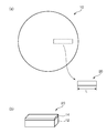
- FIG. 1A is a schematic sectional view illustrating an example of a base material of a cutting blade used in a manufacturing method according to an embodiment of the present invention
- FIG. 1B is a schematic view of the base material of FIG. 1A.
- FIG. 2A is a schematic plan view for explaining the cutting out of the cutting blade forming piece from the base material in the manufacturing method according to the embodiment of the present invention
- FIG. 2B is the cutting out of FIG. 1A.
- It is a schematic perspective view of a cutting blade formation piece.
- FIG. 6 is a schematic cross-sectional view explaining the production of the cutting blade in the manufacturing method according to the embodiment of the present invention.
- FIG. 1A is a schematic sectional view illustrating an example of a base material of a cutting blade used in a manufacturing method according to an embodiment of the present invention
- FIG. 1B is a schematic view of the base material of FIG. 1A.
- FIG. 2A is a schematic plan view for explaining the cutting out of the cutting blade forming piece from
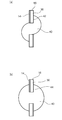
- FIG. 4A is a schematic plan view illustrating an example of attaching the cutting blade to the main body in the manufacturing method according to the embodiment of the present invention
- FIG. 4B is a schematic plan view illustrating another example. is there.
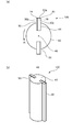
- FIG. 5A is a schematic plan view illustrating an example of the end mill obtained by the embodiment of FIG. 4B
- FIG. 5B is a schematic perspective view of the end mill of FIG. 5A.
- It is a schematic plan view which shows an example of the shape of the non-linearly processed optical film which can be obtained by the manufacturing method of the optical film using the end mill obtained by the manufacturing method of this invention.
- It is a schematic perspective view for demonstrating the cutting process of the optical film using the end mill obtained by the manufacturing method of this invention.
- 8 (a) to 8 (e) are schematic plan views illustrating a series of procedures of non-linear cutting processing which is an example of cutting processing of an optical film using an end mill obtained by the manufacturing method of the present invention. Is.
- the method of manufacturing the end mill of the present invention comprises a base material having a base made of a superhard material and a sintered diamond layer provided on one surface of the base, and electric discharge machining or laser machining. Cutting out a cutting blade forming piece having a predetermined shape by: cutting the base of the cutting blade forming piece to reduce the thickness of the base to obtain a cutting blade; and attaching the cutting blade to the main body. .
- each step will be described in order.
- the base material is prepared.
- 1A is a schematic sectional view illustrating an example of a base material of a cutting blade used in a manufacturing method according to an embodiment of the present invention
- FIG. 1B is a schematic view of the base material of FIG. 1A. It is a perspective view.
- the base material 10 has the base 12 made of a superhard material and the sintered diamond layer 14 provided on one surface of the base 12.
- the matrix 10 can have any suitable shape.
- the base material 10 may have a disk shape (circular shape in plan view) as illustrated.
- a typical example of the cemented carbide material forming the base 12 is cemented carbide.
- the cemented carbide is typically a composite material in which carbides of IVa, Va, and VIa group metals of the periodic table are sintered with an iron-based metal such as Fe, Co, or Ni.
- Specific examples of the cemented carbide include WC-Co alloys, WC-TiC-Co alloys, WC-TaC-Co alloys, WC-TiC-TaC-Co alloys, WC-Ni alloys, WC-Ni alloys. -Cr-based alloys are included.
- the sintered diamond constituting the sintered diamond layer 14 is typically a polycrystalline diamond obtained by baking small particles of diamond together with a binder (for example, metal powder or ceramic powder) at high temperature and high pressure.
- a binder for example, metal powder or ceramic powder
- the characteristics of the sintered diamond can be adjusted by changing the type and blending ratio of the binder.
- the base material 10 has a thickness of, for example, 1.6 mm to 3.2 mm, preferably 1.6 mm to 2.4 mm. If the thickness of the base material is in such a range, it is possible to suppress the warp of the cutting blade forming piece when the cutting blade forming piece is cut out from the base material, and thus, the warp of the obtained cutting blade is suppressed. Can be suppressed. As a result, the cutting blade can be well attached to the end mill body.
- the thickness of the base 12 is, for example, 1.1 mm to 2.8 mm. If the thickness of the base portion is in such a range, similarly to the above, it is possible to suppress the warp of the cutting blade forming piece when the cutting blade forming piece is cut out from the base material, and thereby, the obtained cutting The warp of the blade can be suppressed. As a result, the cutting blade can be well attached to the end mill body.
- the thickness of the sintered diamond layer 14 is, for example, 0.2 mm to 2.8 mm, preferably 0.2 mm to 1.0 mm, and more preferably 0.3 mm to 0.8 mm.
- the base material 10 can be produced by a method well known and used in the industry.
- the cutting blade forming piece 20 is cut out from the base material 10.
- the cutting of the cutting blade forming piece is performed by electric discharge machining or laser machining.
- the electric discharge machining is not particularly limited, and for example, wire cut electric discharge machining or die-sinking electric discharge machining can be used.
- the wire-cut electric discharge machining is performed by melting and removing the base material by using a metal wire as an electrode and immersing the base material in a working liquid to generate an electric discharge phenomenon between the base material and the electrode.
- the die-sinking electric discharge machining is performed, for example, by bringing a graphite electrode or a copper electrode formed in a shape corresponding to a shape to be formed on the base material close to the base material.
- Laser processing is performed by cutting out a base material with a laser beam.
- the cut cutting blade forming piece 20 has a base portion 12 and a sintered diamond layer 14 similar to the base material.
- the thickness of the cutting blade forming piece, the thickness of the base portion, and the thickness of the sintered diamond layer are as described in the section A for the base material.
- the cutting blade forming piece 20 typically has a rectangular plan view shape, as shown in FIG. With such a shape, a cutting blade having a desired shape can be produced by cutting the base portion as described later.
- the length L of the cutting blade forming piece 20 may correspond to the length of the obtained cutting blade.
- the cutting blade forming piece (finally, the cutting blade) can be formed as a seamless one-piece along the length direction.
- the length L of the cutting blade forming piece 20 is preferably 15 mm or more, more preferably 20 mm to 50 mm. With such a length, when the optical film is cut using the obtained end mill, it is possible to cut a work in which a desired number of optical films are laminated, thus improving the cutting efficiency. be able to.
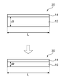
- the cutting blade 30 is obtained by cutting the base portion 12 of the cutting blade forming piece 20 to reduce its thickness. That is, the thickness of the cutting blade 30 is smaller than the thickness of the base material 10 (the thickness of the cutting blade forming piece 20).
- Cutting can typically be done by polishing.
- the polishing is performed by polishing the surface of the base 12 with a flat polishing machine.
- the cutting is not limited to polishing and may be another method. For example, it may be milling, lathing, or wire cutting.
- the obtained cutting blade 30 has a base 16 that has been cut (hereinafter, simply referred to as the base 16 or the base 16 of the cutting blade) and the sintered diamond layer 14.
- the thickness of the cutting blade 30 is, for example, 0.7 mm to 1.6 mm, preferably 0.75 mm to 1.2 mm.
- the base 16 of the cutting blade 30 has a thickness of, for example, 0.2 mm to 1.3 mm, preferably 0.4 mm to 0.9 mm.
- the thickness of the base portion 16 of the cutting blade 30 is smaller than the thickness of the base portion 12 of the base material 10 (the thickness of the base portion 12 of the cutting blade forming piece 20).
- the ratio d 14 / d 16 of the thickness of the sintered diamond layer 14 and the base 16 of the cutting blade 30 is preferably 70% to 400%, more preferably from 100% to 300%.
- the ratio d 14 / d 16 is in such a range, it is possible to obtain the advantage that the strength as a blade can be secured while suppressing the warpage during brazing.
- the main body 40 can be manufactured, for example, by processing a sintered body obtained by a powder metallurgy method known in the art into a predetermined shape (for example, a cylindrical shape) by a method known in the art.
- the cutting blade 30 is attached to the main body 40 by pasting.
- a mounting surface 42 is formed on the body 40.
- the mounting surface 42 may be formed on the body 40 by any suitable method (eg, cutting).
- the bonding is typically performed by brazing (for example, vacuum brazing or high frequency brazing).
- the cutting blade 30 is embedded in the embedding portion 44 provided in the main body 40 (typically, the cutting blade 30 is inserted into the embedding portion 44). It is attached to the main body 40 by.
- the embedded portion 44 can be formed by any suitable method. Specific examples of the forming method include laser processing and cutting processing.
- the depth of the embedding portion 44 is preferably 0.30 mm to 1.50 mm, more preferably 0.30 mm to 1.00 mm, and further preferably 0.30 mm to 0.70 mm.
- the cutting blade 30 is fixed to the embedding portion 44 by vacuum brazing while being embedded in the embedding portion 44.
- the vacuum brazing can satisfactorily adhere to the main body (embedded portion) even with a cutting blade including a sintered diamond layer. This is because residual oxygen and moisture during brazing can be removed, and thus the oxide film on the body surface can be destroyed and the oxide film can be prevented from being regenerated, so that the wettability of the body surface can be increased.
- the number of cutting blades may be one, or may be three or more (for example, three or four).
- the number of cutting blades is preferably 2 to 3. With such a configuration, since the interval between the cutting blades is appropriately secured, cutting scraps can be satisfactorily discharged. More preferably, the number of cutting blades is two. With such a configuration, the rigidity of the cutting blade is ensured, and the pocket is secured, so that cutting scraps can be satisfactorily discharged.
- the cutting edge of the cutting edge is flat has been described, but the cutting edge may be sharp (for example, in FIGS. 4A and 4B, an apex of an acute angle in plan view). You may have).
- the cutting edge can be sharpened by any appropriate cutting process.
- An end mill can be produced as described above.
- FIG. 5 (a) is a schematic plan view illustrating an example of an end mill obtained by the embodiment of FIG. 4 (b), and FIG. 5 (b) is a schematic perspective view of the end mill of FIG. 5 (a).
- the end mill 100 of the illustrated example has a main body 40 that rotates about a rotary shaft 46 that extends in the vertical direction (the stacking direction of the works, the work is a cutting target in which optical films are stacked, details will be described later), and the main body 40.
- a cutting blade 30 protruding from the outermost diameter.
- the end mill is typically a straight end mill.
- the main body 40 is provided with an embedded portion 44, and the cutting blade 30 is embedded in the embedded portion 44 and fixed to the main body 40.
- the cutting blade can be satisfactorily attached to the main body even if the end mill has a small diameter and it is difficult to sufficiently secure the attachment surface of the cutting blade on the main body surface. Therefore, a small-diameter end mill having a practically acceptable cutting ability can be actually manufactured. Furthermore, an end mill excellent in strength and durability can be realized.
- the embedded portions are preferably provided at symmetrical positions with respect to the rotation axis 46. With such a configuration, good cutting can be realized and the strength and durability of the end mill can be further improved.
- the helix angle of the cutting blade 30 is typically 0 °. With such a configuration, it is possible to satisfactorily cut the optical film described below. More specifically, when cutting with a cutting blade having a helix angle (for example, deformed machining or non-linear machining), the cutting surface may have a taper shape when viewed from the lateral direction, but the helix angle is 0 °. By using the cutting blade, it is possible to prevent the cutting surface from being tapered.
- the irregular processing means processing the optical film into a shape other than a rectangle, for example. In particular, a remarkable effect can be obtained when fine non-linear processing (deformation) is performed on the optical film using a small-diameter end mill.
- twist angle is 0 °
- 0 ° means that the cutting blade 30 extends in a direction substantially parallel to the rotary shaft 46, in other words, the blade is not twisted with respect to the rotary shaft.
- 0 ° means substantially 0 °, and also includes a case where a slight angle twist is caused by a processing error or the like.
- the outer diameter of the illustrated end mill is typically less than 10 mm, preferably 3 mm to 9 mm, and more preferably 4 mm to 7 mm. According to the embodiment of the present invention, it is possible to actually manufacture an end mill having such a small outer diameter and practically acceptable cutting ability. As a result, for example, in fine non-linear processing (deformed processing) of an optical film using such a small-diameter end mill, cracks and yellow bands of the optical film can be favorably suppressed, and further, the optical film has an adhesive layer. When it has, it is possible to satisfactorily suppress the lack of glue.
- the “outer diameter of the end mill” refers to a value obtained by doubling the distance from the rotary shaft 46 to the cutting edge 30a.
- the cutting blade 30 typically includes a cutting edge 30a, a rake surface 30b, and a relief surface 30c.
- the rake face 30b is located on the downstream side in the rotation direction R, and the pocket 50 can be defined by the rake face 30b and the main body 40.
- the relief surface 30c (base portion 16) in which the surface of the sintered diamond layer 14 corresponds to the rake surface 30b and the surface of the base portion 16 corresponds to the relief surface 30c is preferably roughened. Any appropriate treatment can be adopted as the surface-roughening treatment. A typical example is blasting.
- blocking refers to a phenomenon in which the optical films in the work adhere to each other with an adhesive or a pressure-sensitive adhesive when the optical film includes an adhesive layer, and a scraping of the adhesive or the pressure-sensitive adhesive attached to the end surface. The dust will contribute to the adhesion between the optical films.
- the end mill obtained by the production method of the present invention can typically be suitably used in the production method of an optical film.
- the manufacturing method preferably includes cutting the end surface of the optical film.
- the optical film examples include a polarizer, a retardation film, a polarizing plate (typically, a laminate of a polarizer and a protective film), a conductive film for a touch panel, a surface-treated film, and for these purposes.
- a laminate for example, a circularly polarizing plate for antireflection, a polarizing plate with a conductive layer for a touch panel
- the optical film includes an adhesive layer (eg, an adhesive layer, a pressure-sensitive adhesive layer).
- the manufacturing method when a polarizing plate with an adhesive layer is adopted as an example of an optical film Specifically, each step in the method of manufacturing a planar polarizing plate with a pressure-sensitive adhesive layer as shown in FIG. 6 will be described. It is obvious to those skilled in the art that the optical film is not limited to the polarizing plate with the pressure-sensitive adhesive layer, and that the planar shape of the polarizing plate with the pressure-sensitive adhesive layer is not limited to the planar shape of FIG. 6. That is, the end mill obtained by the manufacturing method of the present invention can be applied to the manufacturing method of any optical film having any shape.
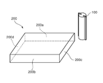
- FIG. 7 is a schematic perspective view for explaining the cutting process of the optical film, and the work piece 200 is shown in this figure.
- a work 200 is formed by stacking a plurality of optical films (polarizing plates with adhesive layers).
- the pressure-sensitive adhesive layer-attached polarizing plate can be manufactured by a method well known and commonly used in the art, and thus a detailed description of the manufacturing method is omitted.
- the polarizing plate with the pressure-sensitive adhesive layer is typically cut into any appropriate shape when forming a work.
- the pressure-sensitive adhesive layer-attached polarizing plate may be cut into a rectangular shape, may be cut into a shape similar to the rectangular shape, or may be cut into an appropriate shape (for example, a circle) according to the purpose. It may have been done.
- the pressure-sensitive adhesive layer-attached polarizing plate is cut into a rectangular shape, and the work 200 has outer peripheral surfaces (cutting surfaces) 200a and 200b facing each other and outer peripheral surfaces (cutting surfaces) 200c and 200d orthogonal thereto.
- the work 200 is preferably clamped from above and below by a clamp means (not shown).
- the total thickness of the work is preferably 10 mm to 50 mm, more preferably 15 mm to 25 mm, and further preferably about 20 mm. With such a thickness, it is possible to prevent damage due to the pressing by the clamp means or the impact during cutting.
- the polarizing plates with the pressure-sensitive adhesive layer are stacked so that the works have such a total thickness.
- the number of pressure-sensitive adhesive layer-attached polarizing plates constituting the work may be, for example, 20 to 100.
- the clamp means eg, jig
- the clamp means may be made of a soft material or a hard material. When it is made of a soft material, its hardness (JIS A) is preferably 60 ° to 80 °. If the hardness is too high, the pressing trace by the clamp means may remain. If the hardness is too low, the jig may be deformed to cause positional deviation, resulting in insufficient cutting accuracy.
- a predetermined position on the outer peripheral surface of the work 200 is cut by the end mill 100.
- the end mill 100 is typically held by a machine tool (not shown), is rotated at a high speed around the rotation axis of the end mill, and is fed in a direction intersecting with the rotation axis while the cutting blade is placed on the outer peripheral surface of the workpiece 200. Used by abutting and cutting. That is, the cutting is typically performed by bringing the cutting blade of the end mill into contact with the outer peripheral surface of the work 200 to make a cut.
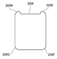
- a pressure-sensitive adhesive layer-attached polarizing plate having a shape in plan view as shown in FIG.
- chamfered portions 200E, 200F, 200G, and 200H are formed at four corners of the outer periphery of the work 200, and chamfered portions 200E and A recess 200I is formed at the center of the outer peripheral surface connecting with 200H.
- FIG. 8A the portion where the chamfered portion 200E of FIG. 6 is formed is chamfered, and then, as shown in FIGS. 8B to 8D, the chamfered portion 200F, The portions where 200G and 200H are formed are sequentially chamfered. Finally, as shown in FIG. 8E, the recess 200I is cut and formed.
- the chamfered portions 200E, 200F, 200G and 200H, and the recess 200I are formed in this order, but they may be formed in any appropriate order.
- the cutting conditions can be appropriately set according to the configuration of the polarizing plate with the pressure-sensitive adhesive layer, the desired shape, and the like.
- the rotation speed (rotation speed) of the end mill is preferably less than 25000 rpm, more preferably 22000 rpm or less, and further preferably 20000 rpm or less.
- the lower limit of the rotation speed of the end mill can be, for example, 10,000 rpm.
- the feed speed of the end mill is preferably 500 mm / min to 10000 mm / min, more preferably 500 mm / min to 2500 mm / min, and further preferably 800 mm / min to 1500 mm / min.
- the cut amount of the end mill is preferably 0.8 mm or less, more preferably 0.3 mm or less.
- the number of cuts at the cutting location by the end mill may be one cut, two cuts, three cuts or more.
- a polarizing plate with a pressure-sensitive adhesive layer that has been machined can be obtained using the end mill obtained by the production method of the present invention.
- a polarizing plate with a pressure-sensitive adhesive layer including a non-linearly processed portion can be obtained.
- the end mill obtained by the manufacturing method of the present invention can be suitably used for cutting an optical film.
- the optical film machined by the end mill of the present invention can be used for, for example, an instrument panel of a car or a deformed image display section represented by a smart watch.
Landscapes
- Engineering & Computer Science (AREA)
- Mechanical Engineering (AREA)
- Milling Processes (AREA)
Priority Applications (2)
| Application Number | Priority Date | Filing Date | Title |
|---|---|---|---|
| CN201980070272.XA CN112930245B (zh) | 2018-10-24 | 2019-09-17 | 立铣刀的制造方法 |
| KR1020217012119A KR102837255B1 (ko) | 2018-10-24 | 2019-09-17 | 엔드 밀의 제조 방법 |
Applications Claiming Priority (2)
| Application Number | Priority Date | Filing Date | Title |
|---|---|---|---|
| JP2018199730A JP7378716B2 (ja) | 2018-10-24 | 2018-10-24 | エンドミルの製造方法 |
| JP2018-199730 | 2018-10-24 |
Publications (1)
| Publication Number | Publication Date |
|---|---|
| WO2020084960A1 true WO2020084960A1 (ja) | 2020-04-30 |
Family
ID=70331345
Family Applications (1)
| Application Number | Title | Priority Date | Filing Date |
|---|---|---|---|
| PCT/JP2019/036356 Ceased WO2020084960A1 (ja) | 2018-10-24 | 2019-09-17 | エンドミルの製造方法 |
Country Status (5)
| Country | Link |
|---|---|
| JP (1) | JP7378716B2 (enExample) |
| KR (1) | KR102837255B1 (enExample) |
| CN (1) | CN112930245B (enExample) |
| TW (1) | TWI794542B (enExample) |
| WO (1) | WO2020084960A1 (enExample) |
Families Citing this family (1)
| Publication number | Priority date | Publication date | Assignee | Title |
|---|---|---|---|---|
| JP7366510B2 (ja) * | 2022-03-14 | 2023-10-23 | 日東電工株式会社 | 複合切削工具およびそれを用いた樹脂シートの製造方法 |
Citations (6)
| Publication number | Priority date | Publication date | Assignee | Title |
|---|---|---|---|---|
| JPH04240004A (ja) * | 1991-01-16 | 1992-08-27 | Sumitomo Electric Ind Ltd | 多結晶ダイヤモンド切削工具およびその製造方法 |
| JPH0623615A (ja) * | 1992-03-09 | 1994-02-01 | Norton Co | ダイアモンドフィルムを用いた切削工具 |
| EP0628369A1 (en) * | 1993-05-13 | 1994-12-14 | Herramientas Preziss, S.L. | Methods for obtaining cutting tools, and cutting tools obtained by these methods |
| JPH09314406A (ja) * | 1996-05-27 | 1997-12-09 | Osaka Diamond Ind Co Ltd | 超硬質切削用チップ及びその製造方法 |
| JP2001030107A (ja) * | 1999-07-23 | 2001-02-06 | Hoei Kogyo:Kk | 軸状回転切削工具 |
| JP2008272863A (ja) * | 2007-04-27 | 2008-11-13 | Allied Material Corp | 気相合成ダイヤモンドチップおよびダイヤモンド工具 |
Family Cites Families (11)
| Publication number | Priority date | Publication date | Assignee | Title |
|---|---|---|---|---|
| JPH08206902A (ja) * | 1994-12-01 | 1996-08-13 | Sumitomo Electric Ind Ltd | 切削用焼結体チップおよびその製造方法 |
| JP2002036008A (ja) * | 2000-07-24 | 2002-02-05 | Ngk Spark Plug Co Ltd | スローアウェイチップ及び切削工具 |
| US20020170407A1 (en) * | 2001-02-20 | 2002-11-21 | Sheffield Saw And Tool Co., Inc. | Polycrystalline cubic baron nitride (PCBN) woodworking tools and methods |
| JP2004026514A (ja) * | 2002-06-21 | 2004-01-29 | Showa Denko Kk | 立方晶窒化ホウ素焼結体及びその製造方法 |
| KR20140002809A (ko) * | 2005-12-12 | 2014-01-08 | 엘리먼트 씩스 (프로덕션) (피티와이) 리미티드 | 절삭 방법 |
| WO2011011771A2 (en) * | 2009-07-24 | 2011-01-27 | Diamond Innovations, Inc. | Metal-free supported polycrystalline diamond (pcd) and method to form |
| CN102658605B (zh) * | 2012-05-02 | 2015-05-20 | 厦门钨业股份有限公司 | 一种超硬材料高耐磨精密支撑架/块的制作方法 |
| DE102014109390A1 (de) * | 2014-07-04 | 2016-01-07 | Jakob Lach Gmbh & Co. Kg | Zerspanungswerkzeug, insbesondere Reib-, Fräs- oder Bohrwerkzeug |
| JP6614491B2 (ja) * | 2014-12-25 | 2019-12-04 | 三菱マテリアル株式会社 | 複合焼結体切削工具および表面被覆複合焼結体切削工具 |
| JP6277150B2 (ja) | 2015-03-26 | 2018-02-07 | ナカオテクニカ株式会社 | 加工装置 |
| WO2017163972A1 (ja) * | 2016-03-25 | 2017-09-28 | 株式会社神戸製鋼所 | 硬質皮膜、硬質皮膜被覆部材及び硬質皮膜の製造方法 |
-
2018
- 2018-10-24 JP JP2018199730A patent/JP7378716B2/ja active Active
-
2019
- 2019-09-17 KR KR1020217012119A patent/KR102837255B1/ko active Active
- 2019-09-17 CN CN201980070272.XA patent/CN112930245B/zh active Active
- 2019-09-17 WO PCT/JP2019/036356 patent/WO2020084960A1/ja not_active Ceased
- 2019-09-23 TW TW108134246A patent/TWI794542B/zh active
Patent Citations (6)
| Publication number | Priority date | Publication date | Assignee | Title |
|---|---|---|---|---|
| JPH04240004A (ja) * | 1991-01-16 | 1992-08-27 | Sumitomo Electric Ind Ltd | 多結晶ダイヤモンド切削工具およびその製造方法 |
| JPH0623615A (ja) * | 1992-03-09 | 1994-02-01 | Norton Co | ダイアモンドフィルムを用いた切削工具 |
| EP0628369A1 (en) * | 1993-05-13 | 1994-12-14 | Herramientas Preziss, S.L. | Methods for obtaining cutting tools, and cutting tools obtained by these methods |
| JPH09314406A (ja) * | 1996-05-27 | 1997-12-09 | Osaka Diamond Ind Co Ltd | 超硬質切削用チップ及びその製造方法 |
| JP2001030107A (ja) * | 1999-07-23 | 2001-02-06 | Hoei Kogyo:Kk | 軸状回転切削工具 |
| JP2008272863A (ja) * | 2007-04-27 | 2008-11-13 | Allied Material Corp | 気相合成ダイヤモンドチップおよびダイヤモンド工具 |
Also Published As
| Publication number | Publication date |
|---|---|
| JP2020066087A (ja) | 2020-04-30 |
| CN112930245A (zh) | 2021-06-08 |
| KR20210076017A (ko) | 2021-06-23 |
| KR102837255B1 (ko) | 2025-07-21 |
| TWI794542B (zh) | 2023-03-01 |
| TW202019591A (zh) | 2020-06-01 |
| JP7378716B2 (ja) | 2023-11-14 |
| CN112930245B (zh) | 2024-07-05 |
Similar Documents
| Publication | Publication Date | Title |
|---|---|---|
| WO2020084960A1 (ja) | エンドミルの製造方法 | |
| JP2012171028A (ja) | スクエアエンドミル | |
| JP2020066087A5 (enExample) | ||
| JP7744116B2 (ja) | 光学フィルム切削用エンドミルおよび該エンドミルを用いた光学フィルムの製造方法 | |
| CN116748577B (zh) | 复合切削工具及使用它的树脂片的制造方法 | |
| JP7345808B2 (ja) | エンドミルおよびその製造方法 | |
| WO2020084958A1 (ja) | エンドミルおよびその製造方法 | |
| TWI902673B (zh) | 含接著層光學薄膜加工用端銑刀及其製造方法 | |
| JP7758570B2 (ja) | 光学フィルム切削用エンドミルおよび該エンドミルを用いた光学フィルムの製造方法 | |
| JP5929144B2 (ja) | 硬質焼結体ボールエンドミル | |
| KR20200095498A (ko) | 경질 코팅층 및 초경 코팅층을 갖는 절삭공구 및 그 제조 방법 | |
| WO2023176342A1 (ja) | 樹脂シートの製造方法 | |
| JPH0379265A (ja) | 被加工物の切断方法 | |
| JP2013136135A (ja) | ボールエンドミル用インサート及び刃先交換式ボールエンドミル |
Legal Events
| Date | Code | Title | Description |
|---|---|---|---|
| 121 | Ep: the epo has been informed by wipo that ep was designated in this application |
Ref document number: 19876241 Country of ref document: EP Kind code of ref document: A1 |
|
| NENP | Non-entry into the national phase |
Ref country code: DE |
|
| 122 | Ep: pct application non-entry in european phase |
Ref document number: 19876241 Country of ref document: EP Kind code of ref document: A1 |