WO2020084944A1 - 基板処理装置および基板処理方法 - Google Patents
基板処理装置および基板処理方法 Download PDFInfo
- Publication number
- WO2020084944A1 WO2020084944A1 PCT/JP2019/035767 JP2019035767W WO2020084944A1 WO 2020084944 A1 WO2020084944 A1 WO 2020084944A1 JP 2019035767 W JP2019035767 W JP 2019035767W WO 2020084944 A1 WO2020084944 A1 WO 2020084944A1
- Authority
- WO
- WIPO (PCT)
- Prior art keywords
- substrate
- etching
- processing apparatus
- substrate processing
- unit
- Prior art date
- Legal status (The legal status is an assumption and is not a legal conclusion. Google has not performed a legal analysis and makes no representation as to the accuracy of the status listed.)
- Ceased
Links
Images




Classifications
-
- H—ELECTRICITY
- H10—SEMICONDUCTOR DEVICES; ELECTRIC SOLID-STATE DEVICES NOT OTHERWISE PROVIDED FOR
- H10P—GENERIC PROCESSES OR APPARATUS FOR THE MANUFACTURE OR TREATMENT OF DEVICES COVERED BY CLASS H10
- H10P72/00—Handling or holding of wafers, substrates or devices during manufacture or treatment thereof
- H10P72/04—Apparatus for manufacture or treatment
- H10P72/0402—Apparatus for fluid treatment
- H10P72/0418—Apparatus for fluid treatment for etching
- H10P72/0422—Apparatus for fluid treatment for etching for wet etching
- H10P72/0424—Apparatus for fluid treatment for etching for wet etching using mainly spraying means, e.g. nozzles
-
- B—PERFORMING OPERATIONS; TRANSPORTING
- B08—CLEANING
- B08B—CLEANING IN GENERAL; PREVENTION OF FOULING IN GENERAL
- B08B3/00—Cleaning by methods involving the use or presence of liquid or steam
-
- G—PHYSICS
- G01—MEASURING; TESTING
- G01J—MEASUREMENT OF INTENSITY, VELOCITY, SPECTRAL CONTENT, POLARISATION, PHASE OR PULSE CHARACTERISTICS OF INFRARED, VISIBLE OR ULTRAVIOLET LIGHT; COLORIMETRY; RADIATION PYROMETRY
- G01J5/00—Radiation pyrometry, e.g. infrared or optical thermometry
- G01J5/48—Thermography; Techniques using wholly visual means
-
- H—ELECTRICITY
- H10—SEMICONDUCTOR DEVICES; ELECTRIC SOLID-STATE DEVICES NOT OTHERWISE PROVIDED FOR
- H10P—GENERIC PROCESSES OR APPARATUS FOR THE MANUFACTURE OR TREATMENT OF DEVICES COVERED BY CLASS H10
- H10P50/00—Etching of wafers, substrates or parts of devices
-
- H—ELECTRICITY
- H10—SEMICONDUCTOR DEVICES; ELECTRIC SOLID-STATE DEVICES NOT OTHERWISE PROVIDED FOR
- H10P—GENERIC PROCESSES OR APPARATUS FOR THE MANUFACTURE OR TREATMENT OF DEVICES COVERED BY CLASS H10
- H10P50/00—Etching of wafers, substrates or parts of devices
- H10P50/60—Wet etching
- H10P50/64—Wet etching of semiconductor materials
- H10P50/642—Chemical etching
-
- H—ELECTRICITY
- H10—SEMICONDUCTOR DEVICES; ELECTRIC SOLID-STATE DEVICES NOT OTHERWISE PROVIDED FOR
- H10P—GENERIC PROCESSES OR APPARATUS FOR THE MANUFACTURE OR TREATMENT OF DEVICES COVERED BY CLASS H10
- H10P52/00—Grinding, lapping or polishing of wafers, substrates or parts of devices
-
- H—ELECTRICITY
- H10—SEMICONDUCTOR DEVICES; ELECTRIC SOLID-STATE DEVICES NOT OTHERWISE PROVIDED FOR
- H10P—GENERIC PROCESSES OR APPARATUS FOR THE MANUFACTURE OR TREATMENT OF DEVICES COVERED BY CLASS H10
- H10P72/00—Handling or holding of wafers, substrates or devices during manufacture or treatment thereof
- H10P72/06—Apparatus for monitoring, sorting, marking, testing or measuring
- H10P72/0602—Temperature monitoring
-
- H—ELECTRICITY
- H10—SEMICONDUCTOR DEVICES; ELECTRIC SOLID-STATE DEVICES NOT OTHERWISE PROVIDED FOR
- H10P—GENERIC PROCESSES OR APPARATUS FOR THE MANUFACTURE OR TREATMENT OF DEVICES COVERED BY CLASS H10
- H10P72/00—Handling or holding of wafers, substrates or devices during manufacture or treatment thereof
- H10P72/06—Apparatus for monitoring, sorting, marking, testing or measuring
- H10P72/0604—Process monitoring, e.g. flow or thickness monitoring
-
- H—ELECTRICITY
- H10—SEMICONDUCTOR DEVICES; ELECTRIC SOLID-STATE DEVICES NOT OTHERWISE PROVIDED FOR
- H10P—GENERIC PROCESSES OR APPARATUS FOR THE MANUFACTURE OR TREATMENT OF DEVICES COVERED BY CLASS H10
- H10P72/00—Handling or holding of wafers, substrates or devices during manufacture or treatment thereof
- H10P72/10—Handling or holding of wafers, substrates or devices during manufacture or treatment thereof using carriers specially adapted therefor, e.g. front opening unified pods [FOUP]
-
- H—ELECTRICITY
- H10—SEMICONDUCTOR DEVICES; ELECTRIC SOLID-STATE DEVICES NOT OTHERWISE PROVIDED FOR
- H10P—GENERIC PROCESSES OR APPARATUS FOR THE MANUFACTURE OR TREATMENT OF DEVICES COVERED BY CLASS H10
- H10P72/00—Handling or holding of wafers, substrates or devices during manufacture or treatment thereof
- H10P72/70—Handling or holding of wafers, substrates or devices during manufacture or treatment thereof for supporting or gripping
- H10P72/76—Handling or holding of wafers, substrates or devices during manufacture or treatment thereof for supporting or gripping using mechanical means, e.g. clamps or pinches
- H10P72/7604—Handling or holding of wafers, substrates or devices during manufacture or treatment thereof for supporting or gripping using mechanical means, e.g. clamps or pinches the wafers being placed on a susceptor, stage or support
- H10P72/7618—Handling or holding of wafers, substrates or devices during manufacture or treatment thereof for supporting or gripping using mechanical means, e.g. clamps or pinches the wafers being placed on a susceptor, stage or support characterised by a movable susceptor, stage or support, others than those only rotating on their own vertical axis, e.g. susceptors on a rotating carrousel
-
- G—PHYSICS
- G01—MEASURING; TESTING
- G01J—MEASUREMENT OF INTENSITY, VELOCITY, SPECTRAL CONTENT, POLARISATION, PHASE OR PULSE CHARACTERISTICS OF INFRARED, VISIBLE OR ULTRAVIOLET LIGHT; COLORIMETRY; RADIATION PYROMETRY
- G01J5/00—Radiation pyrometry, e.g. infrared or optical thermometry
- G01J2005/0077—Imaging
-
- G—PHYSICS
- G01—MEASURING; TESTING
- G01J—MEASUREMENT OF INTENSITY, VELOCITY, SPECTRAL CONTENT, POLARISATION, PHASE OR PULSE CHARACTERISTICS OF INFRARED, VISIBLE OR ULTRAVIOLET LIGHT; COLORIMETRY; RADIATION PYROMETRY
- G01J5/00—Radiation pyrometry, e.g. infrared or optical thermometry
- G01J5/0003—Radiation pyrometry, e.g. infrared or optical thermometry for sensing the radiant heat transfer of samples, e.g. emittance meter
- G01J5/0007—Radiation pyrometry, e.g. infrared or optical thermometry for sensing the radiant heat transfer of samples, e.g. emittance meter of wafers or semiconductor substrates, e.g. using Rapid Thermal Processing
Definitions
- the present invention relates to a technique for etching a substrate.
- the substrate to be processed includes, for example, semiconductor substrates, FPD (Flat Panel Display) substrates such as liquid crystal display devices and organic EL (Electroluminescence) display devices, optical disk substrates, magnetic disk substrates, magneto-optical disk substrates, It includes a photomask substrate, a ceramic substrate, a solar cell substrate, a printed circuit board, and the like.
- etching is performed by supplying an etching liquid to the surface of the substrate.
- Prior arts related to the present invention include those described in Patent Documents 1 and 2, for example.
- Patent Documents 1 and 2 perform etching treatment in a state where the substrate is at an appropriate temperature by monitoring the temperature of the substrate surface and stopping the supply of the etching treatment liquid when the temperature of the substrate reaches a target temperature. Is disclosed.
- the etching process could be affected not only by the temperature of the substrate, but also by the temperature around the substrate.
- the prior art monitors only the temperature of the substrate surface, and does not consider the influence of the ambient temperature around the substrate on etching. Therefore, there is a possibility that the etching process may be defective due to radiant heat from the members around the substrate.
- An object of the present invention is to provide a technique for suitably performing a substrate etching process.
- a first aspect is a substrate processing apparatus for etching a substrate, comprising a chamber having a processing space therein, a substrate holding unit for holding the substrate at a predetermined position in the chamber, An etching liquid supply unit that supplies an etching liquid to the substrate held by the substrate holding unit, a rotating unit that rotates the substrate holding unit around a predetermined rotation axis, and the chamber is disposed at the predetermined position in the chamber. If the temperature distribution acquisition unit that acquires the temperature distribution in the peripheral region around the substrate region occupied by the substrate, and the temperature distribution, the characteristic value related to the etching amount of the substrate by the etching process using the etching solution, And a feature value calculator for calculating.
- the second aspect is the substrate processing apparatus of the first aspect, further including an etching determination unit that determines the quality of the etching processing on the substrate based on a comparison between the characteristic value and a predetermined threshold value.
- a third aspect is the substrate processing apparatus according to the first aspect or the second aspect, wherein the characteristic value calculation unit calculates the characteristic value from a relational expression indicating a relationship between the temperature distribution and the etching amount.
- a fourth aspect is the substrate processing apparatus of the third aspect, wherein the relational expression is generated based on the temperature distribution at a specified timing in the etching process and an etching amount of the substrate on which the etching process is performed. It further comprises a relational expression generator.
- a fifth aspect is the substrate processing apparatus according to the fourth aspect, wherein the characteristic value calculation unit substitutes the temperature distribution at a timing corresponding to the specified timing in the etching process into the relational expression. Calculate the value.
- a sixth aspect is the substrate processing apparatus according to any one of the third to fifth aspects, wherein the etching amount is an etching amount on each circumference having different radii about the rotation axis.
- a seventh aspect is the substrate processing apparatus according to any one of the first to sixth aspects, wherein the temperature distribution acquisition unit includes an area in which a substrate held by the substrate holding unit is arranged in an imaging area. It has a thermography camera and the temperature distribution is thermography.
- An eighth aspect is the substrate processing apparatus of the seventh aspect, wherein the relational expression uses the temperature indicated by each pixel value forming the thermography as an independent variable, and the etching amount on each circumference of the different radius is dependent. It is a regression function that is a variable.
- a ninth aspect is the substrate processing apparatus according to any one of the first to eighth aspects, wherein the characteristic value calculation unit acquires the temperature in a state in which the substrate holding unit does not hold the substrate. The feature value is calculated from the distribution.
- a tenth aspect is the substrate processing apparatus of the ninth aspect, further comprising a temperature changing unit that changes the temperatures of the substrate arranged at the predetermined position and the peripheral region according to the characteristic value.
- An eleventh aspect is the substrate processing apparatus according to the ninth aspect or the tenth aspect, further comprising a schedule changing unit that changes a schedule defining a time for loading the substrate into the chamber according to the characteristic value.
- a twelfth aspect is the substrate processing apparatus according to any one of the first to eighth aspects, in which the characteristic value calculation unit acquires the temperature in a state in which the substrate holding unit holds the substrate. The feature value is calculated from the distribution.
- a thirteenth aspect is the substrate processing apparatus according to the twelfth aspect, further including a temperature changing unit that changes the temperatures of the substrate arranged at the predetermined position and the peripheral region according to the characteristic value.
- a fourteenth aspect is the substrate processing apparatus according to the twelfth aspect or the thirteenth aspect, further comprising a schedule changing unit that changes a schedule that defines a time for loading the substrate into the chamber according to the characteristic value.
- a fifteenth aspect is a substrate processing method, comprising: a) holding a substrate at a predetermined position in a chamber; and b) rotating the substrate at the predetermined position around a rotation axis in step a). c) supplying an etchant to the surface of the substrate rotating by step b), and d) in the chamber in a peripheral region around the substrate region occupied by the substrate when placed in the predetermined position. Obtaining a temperature distribution, and e) calculating a feature value for evaluating an etching process using the etching solution for the substrate from the temperature distribution obtained in step d).
- the characteristic value regarding the etching amount of the substrate is calculated from the temperature distribution around the region where the substrate is arranged. Therefore, based on this characteristic value, it is possible to appropriately evaluate whether or not the etching failure occurs due to the ambient temperature of the substrate.
- the operator can appropriately determine whether or not the etching processing can be performed on the substrate from the temperature distribution of the peripheral region by appropriately setting the threshold value.
- the predicted value of the etching amount can be calculated by substituting the temperature distribution in the relational expression.
- the substrate processing apparatus of the fourth aspect it is possible to obtain the relational expression for predicting the etching amount from the temperature distribution at the specified timing.
- the acquisition timing of the temperature distribution that is substituted into the relational expression for calculating the characteristic value is adjusted to the specified timing of the temperature distribution used to generate the relational expression. Therefore, the characteristic value can be appropriately acquired from the relational expression and the temperature distribution.
- the etching amount on the same circumference on the substrate is almost uniform. Therefore, by obtaining the etching amount on each circumference having different radii, it is possible to efficiently obtain the distribution of the etching amount on the substrate.
- the substrate processing apparatus of the seventh aspect it is possible to easily obtain the temperature distribution around the area where the substrate is arranged by capturing an image with the thermography camera.
- the etching amount is substantially the same on each circumference having different radii. Therefore, the dependent variable can be reduced by setting the etching amounts on the circumferences of different radii as the dependent variables. Thereby, the relational expression for obtaining the etching amount at each point on the substrate can be appropriately and efficiently generated.
- the substrate processing apparatus of the ninth aspect it is possible to inspect whether or not the temperature distribution around the area where the substrate is arranged is suitable for etching before the substrate is held by the substrate holder.
- the substrate processing apparatus of the tenth aspect it is possible to change the temperature distribution around the area where the substrate is arranged so as to be suitable for the etching processing, and therefore it is possible to perform a suitable etching processing.
- the substrate processing apparatus of the eleventh aspect it is possible to delay the loading of the substrate so that the temperature distribution around the area where the substrate is placed has an appropriate temperature. This makes it possible to suppress defects in the etching process on the substrate.
- the substrate processing apparatus of the twelfth aspect after the substrate is held by the substrate holder, it is possible to inspect whether or not the temperature distribution around the region where the substrate is arranged is suitable for etching based on the characteristic value.
- the temperature distribution around the substrate can be changed so as to be suitable for the etching process, so that the etching process can be preferably performed.
- the substrate processing apparatus of the fourteenth aspect it is possible to delay the loading of the substrate until the temperature distribution around the substrate reaches a temperature suitable for the etching process. As a result, defects in the etching process can be suppressed.
- the characteristic value regarding the etching amount of the substrate is calculated from the temperature distribution around the region where the substrate is arranged. Therefore, based on this characteristic value, it is possible to appropriately evaluate whether or not the etching failure occurs due to the ambient temperature of the substrate.
- thermography TH1 notionally. It is a figure which shows the upper surface W1 of the board
- expressions indicating a shape not only represent the shape in a strict geometrical sense, but also within a range in which the same effect can be obtained, for example. A shape having irregularities or chamfers is also shown.
- the expressions “comprising,” “comprising,” “including,” “including,” or “having” one element are not exclusive expressions that exclude the presence of other elements.
- the expression “B on A” includes the case where the two elements A and B are in contact with each other and the case where the two elements A and B are separated from each other.
- FIG. 1 is a diagram showing an overall configuration of a substrate processing apparatus 100 according to the first embodiment.
- the substrate processing apparatus 100 is a single-wafer processing apparatus that processes the substrates W to be processed one by one.
- the substrate processing apparatus 100 performs a cleaning process on a substrate W, which is a circular thin plate-shaped silicon substrate, using an etching solution and a rinse liquid such as pure water, and then performs a drying process.
- a substrate W which is a circular thin plate-shaped silicon substrate
- a rinse liquid such as pure water
- the rinse liquid various liquids such as pure water and ultrapure water may be adopted.
- the etching liquid and the rinsing liquid may be collectively referred to as a “treatment liquid”.
- the substrate processing apparatus 100 includes a plurality of cleaning processing units 1, an indexer 102, and a main transfer robot 103.
- the indexer 102 carries the substrate W to be processed, which is received from the outside of the apparatus, into the apparatus, and carries out the processed substrate W, which has been cleaned, from the apparatus.
- the indexer 102 mounts a plurality of carriers (not shown) and includes a transfer robot (not shown).
- a transfer robot As the carrier, a FOUP (Front Opening Unified Pod) or SMIF (Standard Mechanical InterFace) pod that stores the substrate W in a closed space, or an OC (Open Cassette) that exposes the substrate W to the outside air may be adopted.
- the transfer robot transfers the substrate W between the carrier and the main transfer robot 103.
- the cleaning processing unit 1 performs liquid processing and drying processing on one substrate W. Twelve cleaning processing units 1 are arranged in the substrate processing apparatus 100. Specifically, four towers each including three cleaning processing units 1 stacked vertically are arranged so as to surround the main transfer robot 103. In FIG. 1, one of the cleaning processing units 1 stacked in three stages is schematically shown. The number of cleaning processing units 1 in the substrate processing apparatus 100 is not limited to 12 and may be changed as appropriate.
- the main transfer robot 103 is installed in the center of the four towers in which the cleaning processing units 1 are stacked.
- the main transfer robot 103 carries the substrate W to be processed, which is received from the indexer 102, into each cleaning processing unit 1. Further, the main transfer robot 103 carries out the processed substrate W from each cleaning processing unit 1 and transfers it to the indexer 102.
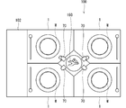
- FIG. 2 is a schematic plan view of the cleaning processing unit 1 of the first embodiment.
- FIG. 3 is a diagram showing the cleaning processing unit 1 and the control unit 9 of the first embodiment. 2 shows a state where the substrate W is not held on the substrate holding stage 20, and FIG. 3 shows a state where the substrate W is held on the substrate holding stage 20.
- the cleaning processing unit 1 includes a substrate holding stage 20 that holds the substrate W in a horizontal posture (a posture in which the normal line of the surface of the substrate W is along the vertical direction) in the chamber 10, and the substrate W held by the substrate holding stage 20.
- the chamber 10 has a processing space TS1 for processing a substrate therein. It is provided with side walls that surround four sides along the vertical direction, a ceiling wall that closes the upper side of the side wall, and a floor wall 13 that closes the lower side of the side wall 11. The space surrounded by the side wall 11, the ceiling wall 12, and the floor wall 13 forms the processing space TS1. A part of the side wall 11 of the chamber 10 is provided with a loading / unloading port for the main transfer robot 103 to load / unload the substrate W and a shutter for opening / closing the loading / unloading port (both not shown). .
- the substrate holding stage 20 is fixed to the upper end of a rotary shaft 24 extending along the vertical direction.
- the central portion of the lower end of the substrate holding stage 20 is connected to the rotating shaft 24.
- the spin motor 22 is connected to the rotary shaft 24.
- the spin motor 22 rotates the rotation shaft 24 around the rotation axis Ax1 according to a control command from the control unit 9.
- the spin motor 22 rotates the rotation shaft 24 to rotate the substrate holding stage 20 in a horizontal plane.
- the substrate holding stage 20 is an example of a substrate holding unit that holds the substrate W at a predetermined position in the chamber 10.
- the spin motor 22 and the rotation shaft 24 are an example of a rotation unit that rotates the substrate holding stage 20 that is a substrate holding unit around a predetermined rotation axis Ax1.
- the periphery of the substrate holding stage 20, the spin motor 22, and the rotating shaft 24 is surrounded by a cover member 23.
- the substrate holding stage 20 has a disc shape.
- the outer diameter of the substrate holding stage 20 is smaller than the diameter of the circular substrate W held by the substrate holding stage 20.
- the substrate holding stage 20 has an upper surface 21 that faces a part of the lower surface of the substrate W to be held.
- a plurality of suction holes are dispersedly provided on the upper surface 21.
- Each suction hole is connected to suction means such as a vacuum pump.
- suction means such as a vacuum pump.
- the substrate holding unit includes the substrate holding stage 20 that sucks the substrate W.
- the substrate holding unit may include a plurality of chuck pins that sandwich the substrate W by supporting different positions on the outer edge of the substrate W.
- the spin motor 22 rotates the rotation shaft 24 while the substrate holding stage 20 holds the substrate W, the substrate W rotates around the rotation axis Ax1 along the vertical direction passing through the center of the substrate W.
- the drive of the spin motor 22 is controlled by the control unit 9.
- the horizontal direction orthogonal to the rotation axis Ax1 is referred to as “radial direction”.
- a direction toward the rotation axis Ax1 in the radial direction is referred to as “radial direction inward”
- a direction away from the rotation axis Ax1 in the radial direction is referred to as “radial direction outward”.
- the nozzle 30 includes ejection heads 31 a and 31 b and a nozzle arm 32.
- the ejection heads 31a and 31b are attached to the tip of the nozzle arm 32.
- the base end side of the nozzle arm 32 is fixedly connected to the nozzle base 33.
- a motor 332 nozzle moving unit, see FIG. 2 provided on the nozzle base 33 is rotatable about an axis along the vertical direction.
- the nozzle 30 moves in the horizontal direction between the position above the substrate holding stage 20 and the standby position outside the processing cup 40, as indicated by the arrow AR34 in FIG. Move in an arc along.
- the nozzle base 33 that is, the nozzle 30 swings above the upper surface 21 of the substrate holding stage 20.
- TP1 a predetermined processing position extending in the horizontal direction. Note that moving the nozzle 30 to the processing position TP1 is synonymous with moving the ejection heads 31a and 31b at the tip of the nozzle 30 to the processing position TP1.
- a processing liquid supply unit 36 is connected to the nozzle 30.
- the processing liquid supply unit 36 includes an etching liquid supply unit 37 and a rinse liquid supply unit 38.
- the etching liquid supply unit 37 is connected to the ejection head 31a and supplies the etching liquid to the ejection head 31a.
- the ejection head 31a ejects the etching liquid toward the upper surface of the rotating substrate W.
- the rinse liquid supply unit 38 is connected to the ejection head 31b and supplies the rinse liquid to the ejection head 31b.
- the ejection head 31b ejects the rinse liquid toward the upper surface of the rotating substrate W.
- the etching liquid supply unit 37 includes a pipe 371 that connects the supply source of the etching liquid and the ejection head 31a, and a valve 372 provided in the pipe 371.
- the rinse liquid supply unit 38 includes a pipe 381 connecting the supply source of the rinse liquid and the ejection head 31b, and a valve 382 provided in the pipe 381.
- the supply valves 372 and 382 open and close each of the pipes 371 and 381 according to a control signal from the control unit 9. As a result, the supply of the processing liquid to the ejection heads 31a and 31b is controlled to be on / off, and at the same time, the ejection of the processing liquid from the ejection heads 31a and 31b is controlled to be turned on / off.
- the number of ejection heads provided in the nozzle 30 is not limited to two, and may be one or three or more. Further, an ejection head may be provided for each type of treatment liquid, or two or more types of treatment liquid may be ejected from the same ejection head. In addition to the nozzle 30, a nozzle that supplies the processing liquid to the substrate W may be provided.
- the nozzle 30 (specifically, the ejection heads 31a and 31b) stops at the processing position TP1 and ejects the processing liquid.
- the processing liquid ejected from the nozzle 30 reaches the upper surface of the substrate W held at the predetermined position on the substrate holding stage 20.
- a heat source 25 is built in the substrate holding stage 20.
- the heat source 25 generates heat according to the control signal from the control unit 9. As a result, the temperatures of the substrate holding stage 20 and the elements arranged around the substrate holding stage 20 are changed. As a result, the substrate W held by the substrate holding stage 20 can be heated.
- the heat source 25 can configure a temperature changing unit that changes the temperature of the substrate W arranged at a predetermined position and the peripheral area PA1 thereof.
- the temperature changing unit that changes the temperature of the substrate W is not limited to the heat source 25 built in the substrate holding stage 20.
- a heat source that is provided outside the substrate holding stage 20 and inside the processing space TS1 of the chamber 10 and applies radiant heat to the substrate W may be adopted.
- a cooling mechanism for cooling the substrate holding stage 20 or its periphery may be provided as the temperature changing unit.
- the processing cup 40 has a cylindrical shape that can surround the outer circumference of the substrate holding stage 20.
- the upper portion of the processing cup 40 has a shape that is inclined vertically upward and radially inward. When the substrate W is held by the substrate holding stage 20, the upper portion of the processing cup 40 surrounds the periphery of the substrate W.
- the processing liquid When the processing liquid is supplied to the upper surface of the substrate W held by the substrate holding stage 20, the processing liquid is shaken off radially outward by the rotation of the substrate W.
- the processing cup 40 receives the processing liquid shaken off from the substrate W on the inner peripheral surface of the upper portion.
- the processing liquid received on the inner peripheral surface falls and is appropriately discharged from the chamber 10.
- the substrate W may be surrounded by a portion of the processing cup 40 that is below the upper portion.
- a mechanism for vertically moving the upper end of the processing cup 40 may be provided.
- the substrate W is loaded onto the substrate holding stage 20, by lowering the upper end of the processing cup 40 below the upper surface 21, it is possible to prevent the substrate W from interfering with the processing cup 40.
- the thermography camera 70 is equipped with an optical system such as a semiconductor lens for detecting heat such as an infrared sensor and a condenser lens.
- the imaging direction of the thermography camera 70 (that is, the optical axis direction of the imaging optical system) is toward the rotation center of the upper surface of the substrate W (or the vicinity thereof) in order to image the upper surface of the substrate W held by the substrate holding stage 20. It is set diagonally downward. In the horizontal direction, the imaging area PA surrounded by a broken line in FIG. 2 is included in the visual field of the thermography camera 70.
- the imaging area PA of the thermography camera 70 includes the peripheral area PA1 around the substrate area occupied by the substrate W when the substrate W is held by the substrate holding stage 20 in the processing space TS1 in the chamber 10. It is set.
- thermography generation unit 901 of the control unit 9 generates a thermography according to the input electric signal.
- the thermography is an example of information indicating the temperature distribution in the imaging area PA (including the peripheral area PA1) of the thermography camera 70.
- the upper end of the processing cup 40 in the peripheral area PA1, the upper end of the processing cup 40, the upper surface W1 of the substrate W (the upper surface 21 of the substrate holding stage 20 when the substrate W is not present), and the nozzle at the processing position TP1.
- Members disposed around the substrate W such as the tip portions of the ejection heads 31a and 31b of 30, are included.
- the peripheral region PA1 may include a part of each element such as the sidewall 11 of the chamber 10 and the nozzle arm 32.
- the acquired thermography includes the temperature distribution on the upper surface 21 of the substrate holding stage 20.
- the upper surface 21 of the substrate holding stage 20 is placed on the back side of the substrate W. Therefore, the acquired thermography does not include the temperature distribution on the upper surface 21.
- the nozzle 30 is arranged at the processing position TP1, part of the nozzle 30 (for example, the ejection heads 31a and 31b) and the like are included in the thermography. As described above, the elements included in the imaging area PA of the thermography camera 70 change according to the situation, so that the elements included in the thermography also change.
- the control unit 9 controls the operation of each element of the substrate processing apparatus 100.
- the hardware configuration of the control unit 9 is similar to that of a general computer. That is, the control unit 9 stores a CPU that performs various arithmetic processes, a ROM that is a read-only memory that stores a basic program, a RAM that is a readable / writable memory that stores various information, and a control application or data.
- the storage unit 91 is provided.
- the display unit 92, the operation unit 93, and the notification unit 94 are connected to the control unit 9.
- the display unit 92 is a display device that displays various images according to an image display signal from the control unit 9.
- the operation unit 93 is an input device such as a mouse and a keyboard that receives an input operation of an operator.
- the notification unit 94 has a function of notifying an abnormality in each cleaning processing unit 1 when the abnormality should be notified to the operator.
- an alarm device such as a lamp or a buzzer may be adopted.
- the notification unit 94 notifies the outside to that effect.
- the display unit 92 may display a default image such as a warning screen. In this way, the display unit 92 may function as the notification unit.
- control unit 9 When the CPU operates according to the control application program stored in the storage unit 91 or the like, the control unit 9 functions as the thermography generation unit 901, the characteristic value calculation unit 902, the prescribed process execution unit 903, and the relational expression generation unit 904. . Note that some or all of these functions may be implemented by hardware by a dedicated circuit.
- the thermography generation unit 901 generates thermography based on the output signal of the thermography camera 70.
- the thermography is an image showing the temperature distribution in the imaging region of the thermography camera 70.
- the characteristic value calculation unit 902 calculates a characteristic value from the temperature distribution indicated by the thermography generation unit 901.
- the feature value is a value related to the etching amount of the substrate W by the etching process using the etching solution executed in the cleaning processing unit 1.
- the prescribed process execution unit 903 executes the prescribed process according to the characteristic value calculated by the characteristic value calculation unit 902.
- the prescribed process execution unit 903 includes an etching determination unit 9031, a temperature control unit 9032, a schedule changing unit 9033, and an output control unit 9034.
- the relational expression generating unit 904 generates a relational expression 912 indicating a correspondence relationship between the temperature distribution (thermography) in the peripheral area PA1 and the etching amount of the substrate W after the predetermined etching process is performed.
- the relational expression 912 may be acquired by experimentally performing the etching process in each cleaning processing unit 1. Further, the relational expression 912 may be acquired by simulation.
- the etching determination unit 9031 determines the quality of the etching process on the substrate W based on the comparison between the determination threshold value 914 that is appropriately determined and the feature value calculated by the feature value calculation unit 902.
- the temperature control unit 9032 controls the heat source 25 according to the thermography acquired by the thermography camera 70.
- the schedule changing unit 9033 changes the schedule that defines the time of each processing executed in each cleaning processing unit 1.
- the schedule defines, for example, a processing schedule for loading the substrate W into each chamber 10 and a discharge time of the processing liquid discharged from the nozzle 30 to the substrate W.
- the output control unit 9034 controls the operations of the display unit 92 and the notification unit 94, which are output devices. For example, the output control unit 9034 causes the display unit 92 to display various images or causes the notification unit 94 to notify according to the result of the determination made by the etching determination unit 9031.
- the relational expression 912 is a mathematical expression for obtaining a predicted value of the etching amount when the etching process is performed under the temperature distribution condition from the temperature distribution of the peripheral area PA1 around the substrate W.
- the relational expression 912 is obtained by multiple regression analysis using the etching amount as an objective variable (dependent variable) and the temperature distribution indicated by the thermography as an explanatory variable (independent variable).
- etching processing is performed under different conditions, and a thermography obtained at that time and a data set of the etching amount of the substrate W are prepared in advance.
- the different conditions may be that the processing conditions are the same and the production lots are different, or that the heating temperature of the substrate W and the temperature conditions of at least one of the peripheral area PA1 are different.
- the thermography corresponding to the independent variable (explanatory variable) of the relational expression 912 is acquired at the specified timing in the etching process.
- the etching process includes a loading stage in which the main transfer robot 103 loads the chamber 10, an etching liquid supply stage in which an etching liquid is supplied to the substrate W held by the substrate holding stage 20 for processing, and a rinse liquid is supplied in the substrate W. It includes a rinse solution supply stage for processing.
- the loading stage is a state in which the substrate W is not held by the substrate holding stage 20. Therefore, when the specified timing is the loading stage, the acquired thermography does not include the temperature distribution information of the upper surface W1 of the substrate W, but includes the temperature distribution information of the upper surface 21 of the substrate holding stage 20.
- the stage after the loading stage is a state where the substrate W is held by the substrate holding stage 20.
- the acquired thermography includes the temperature distribution information of the upper surface W1 of the substrate W.
- FIG. 4 is a diagram conceptually showing the thermography TH1.
- the thermography TH1 is composed of, for example, 640 horizontal pixels and 480 vertical pixels.
- the pixel value X j of each pixel P j (j is a natural number from 1 to N) indicates the temperature of the actual position corresponding to each pixel.
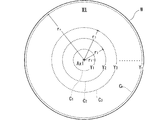
- FIG. 5 is a diagram showing the upper surface W1 of the substrate W.
- the etching amount is measured after each etching process performed under different conditions.
- the etching amount may be measured at only one specific point on the upper surface W1 of the substrate W, or may be measured at different points on the upper surface W1.
- the etching amount Y i may be obtained for each of the circumferences C i of different radii r i (i is a natural number from 1 to n) with the rotation axis Ax1 as the center.
- the average value of the etching amounts measured at a plurality of points on one circumference C i may be set as the etching amount Y i on the circumference C i .
- the etching amount measured at only one point on one circumference C i may be set as the etching amount Y i of the circumference C i .
- the reason for obtaining the etching amount for each circumference C i is to be considered that the amount of etching is liable to be uniform on the same circumference C i.
- the etching liquid supplied near the center of the substrate W (rotation axis Ax1) is concentric with the center of the substrate W. spread. For this reason, the thickness of the etching solution during the etching process tends to be almost the same for each circumference. Further, since the substrate W rotates, it is considered that the influence of the temperature distribution in the peripheral area PA1 around the substrate W on the etching is uniform over one round in each circumference.
- the etching amount on the substrate W does not become uniform on the same circumference C i . Therefore, the etching condition on the upper surface W1 of the substrate W can be appropriately grasped by obtaining the etching amount for each circumference having different radii.
- the relational expression generation unit 904 obtains the relational expression 912 which is a regression function by multiple regression analysis.
- the etching amount Y i is used as an objective variable (dependent variable)
- the pixel value X j of the thermography is used as an explanatory variable (independent variable)
- the following equation (1) is given for each circumference C i (radial distance r i ).
- ⁇ i (i is a natural number from 1 to N)
- various machine learning methods such as L1 normalization (Lasso) regression, L2 normalization (Ridge) regression, and L1 + L2 (Elastic Net) normalization regression may be adopted.
- the specified timing is not limited to one.
- a plurality of specified timings may be set. In this case, it is advisable to generate the regression function at each specified timing.
- the predicted value of the etching amount can be calculated at each timing corresponding to each specified timing, it is possible to inspect whether or not etching is possible at each timing.
- a plurality of prescribed timings may be set for each of the stages before the substrate is loaded and after the substrate is loaded.
- the feature value calculation unit 902 When performing the etching process in the cleaning processing unit 1, the feature value calculation unit 902 obtains the thermographic data obtained at the timing corresponding to the specified timing (the time at which the thermography used to generate the relational expression 912 is acquired). , To the relational expression 912. When the relational expression 912 is generated by using the thermographs having a plurality of specified timings, the feature value calculation unit 902 substitutes the thermographic data of each timing corresponding to each specified timing into the relational expression 912. This value calculated by indicates the predicted value of the etching amount of each circumferential C i expected to be obtained by the circumference C i for each etching process. As described above, by using the relational expression 912, the etching amount of the substrate W can be predicted from the thermography obtained by imaging including the peripheral area PA1 around the substrate W.
- the determination threshold value 914 is set for the etching determination unit 9031 to determine whether or not the predicted value of the etching amount indicated by the feature value is appropriate in advance.
- the determination threshold value 914 is, for example, the in-plane average value Y Ave of the etching amounts calculated by the following equation (2) (the average value of the etching amounts Y 1 to Y n of the circumferences C 1 to C n of the substrate W). May be included in the pass / fail reference value (maximum value ST1 max and minimum value ST1 min ).
- the characteristic value calculation unit 902 may calculate the in-plane average value Y Ave as the characteristic value from the etching amounts Y 1 to Y n (predicted value) obtained from the relational expression 912 (regression function).
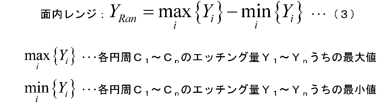
- the determination threshold value 914 is the maximum value in the in-plane range Y Ran (the etching amount Y 1 to Y n of each circumference C 1 to C n of the substrate W) calculated by the following equation (3).
- a pass / fail reference value (maximum value ST2 max ) for the minimum value difference) may be included.
- the feature value calculation unit 902 may calculate the in-plane range Y Ran as a feature value from the etching amounts Y 1 to Y n (predicted value) obtained from the relational expression 912 (regression function).
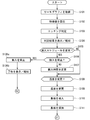
- FIG. 6 is a diagram showing the first half of the etching process sequence.
- FIG. 7 is a diagram showing the latter half of the etching process sequence.
- Each process shown in FIGS. 6 and 7 is performed under the control of the control unit 9 unless otherwise specified.
- the sequence shown in FIGS. 6 and 7 is from the stage before the substrate W to be etched is loaded into the single cleaning processing unit 1 to the stage after the substrate W is processed by the etching liquid and then unloaded. Shows a series of processing of. It is not essential that the processes shown in FIGS. 6 and 7 be executed, and some of them may be omitted. In addition, each process may be executed in a different order as long as no contradiction occurs.
- thermography is acquired (FIG. 6: step S101). Specifically, the thermography camera 70 images the imaging area PA, and the thermography generation unit 901 generates thermography based on the output signal thereof. Since the substrate W is not held by the substrate holding stage 20, the generated thermography includes information on the temperature distribution in the upper surface 21 of the substrate holding stage 20 and the peripheral area PA1.
- the characteristic value calculation unit 902 substitutes the thermography into the relational expression 912 to calculate the characteristic value (FIG. 6: step S102).
- the relational expression 912 used here is a regression function generated from the data set of the thermography and the etching amount before the substrate loading. By substituting the thermography into this relational expression 912, the predicted value of the etching amount before the substrate is loaded can be obtained. Further, the characteristic value calculation unit 902 calculates the characteristic value for the etching determination of the next step from the predicted value obtained from the relational expression 912.
- the characteristic value is, for example, the in-plane average value Y Ave of the etching amount (predicted value) or the in-plane range Y Ran .
- the etching determination unit 9031 makes an etching determination (FIG. 6: step S103). That is, the etching determination unit 9031 determines the quality of the etching process based on the comparison between the feature value obtained in step S102 and the determination threshold value 914.
- the pass / fail reference value (maximum value ST1 max and minimum value ST1 min ) of the in-plane average value Y Ave of the etching amount is set as the determination threshold value 914, the circumferences C 1 to C calculated as the characteristic values are set. It may be determined whether or not the in-plane average value of n is between the minimum value ST1 min and the maximum value ST1 max , which are the quality reference values. If the in-plane average value Y Ave is within the range of the quality standard value, a positive evaluation is given, and if it is in the range image, a negative evaluation is given.
- the etching amount (maximum value ST2 max) is set as the determination threshold value 914, whether the calculated plane range Y Ran as a characteristic value less than the quality reference value not It is good to judge whether or not. If the in-plane range Y Ran is equal to or less than the pass / fail reference value, a positive evaluation is given, and if it exceeds the pass / fail reference value, a negative evaluation is given.
- Step S104 the output control unit 9034 of the prescribed process execution unit 903 executes the process of displaying the positive / negative evaluation according to the result of the etching determination on the display unit 92 or the process of informing the notification unit 94.
- the process of step S104 is an example of the regulation process.
- the schedule changing unit 9033 determines whether to change the processing schedule of the substrate W (FIG. 6: step S105). Specifically, when the etching determination result of step S103 is affirmative, the temperature distribution of the upper surface 21 of the substrate holding stage 20 and the peripheral area PA1 is in a preferable state. Therefore, the schedule changing unit 9033 may determine in step S105 that the process schedule need not be changed. In this case, the following steps S106 and 107 are skipped.
- step S103 If the etching determination result in step S103 is negative, it is considered that the temperature distribution of the upper surface 21 of the substrate holding stage 20 and the peripheral region PA1 is not suitable for the etching process. Therefore, the schedule changing unit 9033 may determine in step S105 that the processing schedule needs to be changed. In this case, the next step S106 is performed.
- Step S106 is a step in which the schedule changing unit 9033 determines whether or not the carry-in to the chamber 10 is prohibited. For example, when the feature value acquired in step S102 deviates from the determination threshold value 914 by more than a predetermined size, it is determined that the loading of the substrate W into the corresponding chamber 10 is prohibited. When carrying-in is prohibited (YES in step S106), the processing schedule is changed so as not to be carried-in (FIG. 6: step S106a). Further, the schedule changing unit 9033 causes the display unit 92 to display a warning indicating that the carry-in is prohibited, and causes the notification unit 94 to notify (FIG. 6: step S106b). Then, the control unit 9 ends the sequence of the etching process.
- step S106 if the carry-in of the substrate W is not prohibited (NO in step S106), the schedule changing unit 9033 changes the process schedule so as to delay the carry-in time (FIG. 6: step S107).
- Each process of changing the transfer schedule such as steps S106a and 107, is an example of a specified process that is performed according to the result of the etching determination.
- the schedule changing unit 9033 may change the processing schedule so as to uniformly prohibit the loading of the substrate W into the corresponding chamber 10.
- the temperature control unit 9032 of the prescribed process execution unit 903 determines whether to change the temperature of the peripheral area PA1 (FIG. 6: step S108). This determination may be performed based on, for example, a comparison (for example, comparison of average values) between the thermography obtained in step S101 and the standard thermography prepared before the substrate loading.
- the temperature control unit 9032 determines to change the temperature (YES in step S108)
- the temperature control unit 9032 changes the temperature according to the state of the thermography (FIG. 6: step S109). For example, when the thermography shows a temperature higher than the standard, the heat source 25 reduces the amount of heat applied to the substrate holding stage 20, and in the opposite case, the heat source 25 increases the amount of heat applied to the substrate holding stage 20. In this way, the temperature controller 9032 changes the temperatures of the peripheral area PA1 and the upper surface 21 of the substrate holding stage 20.
- the process of changing the temperature of the peripheral area PA1 is an example of the defining process performed according to the result of the etching determination.
- step S109 is skipped.
- the main transfer robot 103 carries in the substrate W to be etched into the chamber 10 (FIG. 6: step S110).
- the substrate W carried into the chamber 10 is held by the substrate holding stage 20 (FIG. 6: step S111).
- the control unit 9 moves the nozzle 30 to the processing position TP1 so that the processing liquid can be supplied to the upper surface W1 of the substrate W.
- the spin motor 22 starts rotating the substrate W (FIG. 7: step S112).
- the rotation speed of the substrate W reaches a predetermined rotation speed (for example, 300 rpm)
- the etching liquid supply unit 37 of the processing liquid supply unit 36 supplies the etching liquid to the nozzle 30.
- the etching liquid is supplied from the nozzle 30 to the upper surface W1 of the substrate W (FIG. 7: step S113).
- the etching liquid supplied to the substrate W spreads over the entire upper surface W1 of the substrate W by the rotation of the substrate W to form a liquid film. As a result, the etching reaction proceeds on the entire upper surface W1.
- thermography generation unit 901 generates a thermography from the imaged data of the thermography camera 70.
- the thermography obtained at this stage includes information on the temperature distribution in the upper surface W1 of the substrate W and the peripheral area PA1.
- the characteristic value calculation unit 902 substitutes the thermography into the relational expression 912 to calculate the characteristic value (FIG. 7: step S115).
- the relational expression 912 used here is a regression function generated from the data set of the thermography and the etching amount in the etching liquid supply stage after the substrate is loaded. By substituting the thermography into this relational expression 912, the predicted value of the etching amount at the etching solution supply stage can be obtained. Further, the feature value calculation unit 902 calculates the feature value from the predicted value obtained from the relational expression 912 for the etching determination of the next step.
- the characteristic value is, for example, the in-plane average value Y Ave of the etching amount (predicted value) or the in-plane range Y Ran .
- the etching determination unit 9031 makes an etching determination (FIG. 7: step S116). That is, the etching determination unit 9031 determines the quality of the etching process based on the comparison between the feature value obtained in step S102 and the determination threshold value 914. This determination process is similar to step S103 shown in FIG.
- Step S117 The process of step S117 is an example of the regulation process.
- the schedule changing unit 9033 determines whether to change the processing schedule according to the etching determination result (FIG. 7: step S118).
- the etching determination result of step S103 is a positive evaluation
- the temperature distribution of the upper surface W1 of the substrate W and the peripheral region PA1 is in a preferable state.
- the schedule changing unit 9033 may determine in step S118 that the processing schedule need not be changed. In this case, the next step S119 is skipped.
- the schedule changing unit 9033 may determine in step S118 that the processing schedule needs to be changed. In this case, the schedule changing unit 9033 changes the processing schedule so that the supply time of the etching liquid is changed (FIG. 7: step S119).
- the temperature control unit 9032 of the prescribed process execution unit 903 determines whether to change the temperature of the peripheral area PA1 (FIG. 7: step S120). This determination may be performed based on, for example, comparison (for example, comparison of average values) between the thermography obtained in step S114 and the standard thermography prepared in advance in the etching solution supply stage.
- the temperature control unit 9032 determines to change the temperature (YES in step S120)
- the temperature control unit 9032 changes the temperature according to the state of the thermography (FIG. 7: step S121). For example, when the thermography shows a temperature higher than the standard, the heat source 25 reduces the amount of heat applied to the substrate holding stage 20, and in the opposite case, the heat source 25 increases the amount of heat applied to the substrate holding stage 20. In this way, the temperature controller 9032 changes the temperatures of the peripheral region PA1 and the upper surface W1 of the substrate W.
- the process of changing the temperature of the peripheral area PA1 is an example of the defining process performed according to the result of the etching determination.
- step S121 is skipped.
- step S121 the control unit 9 controls the processing liquid supply unit 36 to stop the supply of the etching liquid to the nozzle 30 and start the supply of the rinse liquid.
- the rinse liquid is supplied from the nozzle 30 to the upper surface W1 of the substrate W (FIG. 7: step S122).
- the control unit 9 stops the supply of the rinse liquid to the nozzle 30.
- Step S123 the control unit 9 controls the spin motor 22 to increase the rotation speed.
- the rinse liquid remaining on the upper surface W1 of the substrate W is scattered radially outward. Thereby, the upper surface W1 of the substrate W is dried.
- the control unit 9 stops the rotation of the substrate W.
- the substrate holding stage 20 releases the substrate W by releasing the suction of the substrate W.
- the main transfer robot 103 carries out the substrate W from the chamber 10 (FIG. 7: step S124).
- ⁇ Effect> According to the substrate processing apparatus 100, not only the temperature distribution of the occupied area occupied by the substrate W but also the temperature distribution of the surrounding area PA1 around it is acquired. By substituting the temperature distribution of the peripheral area PA1 into the relational expression 912, the feature value regarding the estimated blood of the etching amount is calculated. Therefore, the predicted etching amount can be calculated accurately.
- FIG. 7 is a diagram showing the cleaning processing unit 1 and the control section 9A of the second embodiment.
- the control unit 9A of the second embodiment includes a feature value calculation unit 902A and a default process execution unit 903A.
- the default process execution unit 903A includes an etching determination unit 9031A.
- the feature value calculation unit 902A calculates a feature vector, which is an array of a plurality of types of feature amounts, as a feature value from the thermography generated by the thermography generation unit 901.
- a feature amount for example, the sum of pixel values of the thermographic image or the standard deviation of pixel values can be adopted. Further, the pixel value of each pixel of the thermography may be directly used as the feature vector.
- the etching determination unit 9031A performs the etching determination using the classifier K2 that classifies between the good etching class and the poor etching class based on the feature vector calculated from the thermography.
- the good etching class is a class showing that the etching process is good
- the poor etching class is a class showing that the etching process is bad.
- the etching determination unit 9031A gives a positive evaluation.
- the etching determination unit 9031A gives a negative evaluation.
- the classifier K2 performs the etching process under different conditions in the cleaning processing unit 1, and obtains the thermography (temperature distribution) obtained at that time and the etching of the substrate W. Generated by machine learning using a quantity data set. Specifically, teacher data in which a class is taught based on the etching amount result is prepared for each thermography. When teaching a class for thermography, it is advisable to teach a good etching class if the actual etching amount is good, and teach a poor etching class for the opposite. As a result, thermography (specifically, a feature vector) and teacher data composed of a plurality of taught classes are prepared in advance. Then, the classifier K2 is generated by performing machine learning using the teacher data. As the machine learning, a known method such as a neural network, a decision tree, a support vector machine (SVM), or discriminant analysis may be adopted.
- SVM support vector machine
- the generation unit that generates the classifier K2 by machine learning may be included in the substrate processing apparatus 100, or may be included in an apparatus (server or the like) outside the substrate processing apparatus 100. In the latter case, the classifier K2 may be provided to the substrate processing apparatus 100 via a network or various portable media.
- a feature vector is calculated as a feature value from thermography of a region including the peripheral region PA1, and good etching or poor etching is determined based on the feature vector. Therefore, the quality of the etching can be accurately determined at each stage of the etching process. Further, it is possible to perform a prescribed process suitable for the etching process according to the result of the etching determination.
Landscapes
- Physics & Mathematics (AREA)
- General Physics & Mathematics (AREA)
- Spectroscopy & Molecular Physics (AREA)
- Cleaning Or Drying Semiconductors (AREA)
- Chemical & Material Sciences (AREA)
- Chemical Kinetics & Catalysis (AREA)
- General Chemical & Material Sciences (AREA)
- Weting (AREA)
Abstract
Description
図1は、第1実施形態の基板処理装置100の全体構成を示す図である。基板処理装置100は、処理対象である基板Wを1枚ずつ処理する枚葉式の処理装置である。基板処理装置100は、円形薄板状であるシリコン基板である基板Wに対して、エッチング液および純水などのリンス液を用いて洗浄処理を行った後、乾燥処理を行う。エッチング液としては、フッ酸や硝酸などを含む各種の薬液を採用してもよい。リンス液としては、純水や超純水などの各種の液体を採用してもよい。以下の説明では、エッチング液とリンス液を総称して「処理液」と称する場合がある。
以下、基板処理装置100に搭載された12個の洗浄処理ユニット1のうちの1つに説明するが、他の洗浄処理ユニット1についても、ノズル30の配置関係が異なる点以外は、同一の構成を有する。
関係式912は、基板W周辺の周辺領域PA1の温度分布から、その温度分布状況下でエッチング処理を行った場合のエッチング量の予測値を求めるための数式である。関係式912は、エッチング量を目的変数(従属変数)、サーモグラフィが示す温度分布を説明変数(独立変数)とする重回帰分析によって求められる。

判定用閾値914は、特徴値が示すエッチング量の予測値が予め適正かどうかをエッチング判定部9031が判定するために設定される。判定用閾値914は、例えば、次式(2)で算出されるエッチング量の面内平均値YAve(基板Wの各円周C1~Cnのエッチング量Y1~Ynの平均値)について良否基準値(最大値ST1maxおよび最小値ST1min)を含めてもよい。この場合、特徴値演算部902は、関係式912(回帰関数)から求められるエッチング量Y1~Yn(予測値)から、面内平均値YAveを特徴値として算出するとよい。

次に、基板処理装置100において実施されるエッチング処理のシーケンスについて説明する。図6は、エッチング処理のシーケンスの前半部を示す図である。図7は、エッチング処理のシーケンスの後半部を示す図である。図6および図7に示す各処理は、特に断らない限り、制御部9の制御下で行われるものとする。図6および図7に示すシーケンスは、1つの洗浄処理ユニット1に対して、エッチング処理対象の基板Wが搬入される前の段階から、基板Wがエッチング液で処理された後搬出される段階までの一連の処理を示している。図6および図7に示す各処理が実行されることは必須ではなく、一部を省略してもよい。また、各処理は、矛盾が生じない限りにおいて、異なる順番で実行されてもよい。
基板処理装置100によれば、基板Wが占有する占有領域の温度分布だけではなく、そのまわりの周辺領域PA1の温度分布も取得される。この周辺領域PA1の温度分布を関係式912に代入することによって、エッチング量の予測血に関する特徴値が算出される。このため、予測されるエッチング量を精度良く算出できる。
次に、第2実施形態について説明する。なお、以降の説明において、既に説明した要素と同様の機能を有する要素については、同じ符号又はアルファベット文字を追加した符号を付して、詳細な説明を省略する場合がある。
10 チャンバ
11 側壁
20 基板保持ステージ
21 上面
22 スピンモータ
25 熱源
30 ノズル
36 処理液供給部
37 エッチング液供給部
40 処理カップ
70 サーモグラフィカメラ
9,9A 制御部
91 記憶部
92 表示部
93 操作部
94 報知部
901 サーモグラフィ生成部
902,902A 特徴値演算部
903,903A 規定処理実行部
9031,9031A エッチング判定部
9032 温度制御部
9033 スケジュール変更部
9034 出力制御部
904 関係式生成部
912 関係式(回帰関数)
914 判定用閾値
100 基板処理装置
103 主搬送ロボット
Ax1 回転軸線
K2 分類器
PA 撮像領域
PA1 周辺領域
TH1 サーモグラフィ
TS1 処理空間
W 基板
W1 上面
YAve 面内平均値(特徴値)
YRan 面内レンジ(特徴値)
Yi エッチング量
ri 半径距離
Claims (15)
- 基板をエッチング処理する基板処理装置であって、
内部に処理空間を有するチャンバと、
前記チャンバ内における既定位置に基板を保持する基板保持部と、
前記基板保持部に保持された前記基板にエッチング液を供給するエッチング液供給部と、
前記基板保持部を既定の回転軸線まわりに回転させる回転部と、
前記チャンバ内のうち、前記既定位置に配された場合に前記基板が占有する基板領域の周りの周辺領域における温度分布を取得する温度分布取得部と、
前記温度分布から、前記エッチング液を用いたエッチング処理による前記基板のエッチング量に関する特徴値を算出する特徴値演算部と、
を備える、基板処理装置。 - 請求項1の基板処理装置であって、
前記特徴値と予め定められた閾値との比較に基づいて、前記基板に対するエッチング処理の良否を判定するエッチング判定部、をさらに含む、基板処理装置。 - 請求項1または請求項2の基板処理装置であって、
前記特徴値演算部は、前記温度分布と前記エッチング量との関係を示す関係式とから前記特徴値を算出する、基板処理装置。 - 請求項3の基板処理装置であって、
前記エッチング処理における規定タイミングでの前記温度分布、および当該エッチング処理が行われた前記基板のエッチング量に基づいて、前記関係式を生成する関係式生成部、
をさらに備える、基板処理装置。 - 請求項4の基板処理装置であって、
前記特徴値演算部は、前記エッチング処理における前記規定タイミングに対応するタイミングの前記温度分布を前記関係式に代入することによって、前記特徴値を算出する、基板処理装置。 - 請求項3から請求項5のいずれか1項の基板処理装置であって、
前記エッチング量は、前記回転軸線を中心とする、異なる半径の各円周上におけるエッチング量である、基板処理装置。 - 請求項1から請求項6のいずれか1項の基板処理装置であって、
前記温度分布取得部は、前記基板保持部によって保持される基板が配置される領域を撮像領域に含むサーモグラフィカメラを有し、
前記温度分布は、サーモグラフィである、基板処理装置。 - 請求項7の基板処理装置であって、
前記関係式は、前記サーモグラフィを構成する各画素値が示す温度を独立変数とし、前記異なる半径の各円周上のエッチング量を従属変数とする回帰関数である、基板処理装置。 - 請求項1から請求項8のいずれか1項の基板処理装置であって、
前記特徴値演算部は、前記基板保持部が前記基板を保持していない状態で取得される前記温度分布から前記特徴値を算出する、基板処理装置。 - 請求項9の基板処理装置であって、
前記特徴値に応じて、前記既定位置に配された基板及び前記周辺領域の温度を変更する温度変更部、
をさらに備える、基板処理装置。 - 請求項9または請求項10の基板処理装置であって、
前記特徴値に応じて、前記チャンバに前記基板が搬入される時間を規定したスケジュールを変更するスケジュール変更部、
をさらに備える、基板処理装置。 - 請求項1から請求項8のいずれか1項の基板処理装置であって、
前記特徴値演算部は、前記基板保持部が前記基板を保持している状態で取得される前記温度分布から前記特徴値を算出する、基板処理装置。 - 請求項12の基板処理装置であって、
前記特徴値に応じて、前記既定位置に配された基板及び前記周辺領域の温度を変更する温度変更部、
をさらに備える、基板処理装置。 - 請求項12または請求項13の基板処理装置であって、
前記特徴値に応じて、前記チャンバに前記基板が搬入される時間を規定したスケジュールを変更するスケジュール変更部、
をさらに備える、基板処理装置。 - 基板処理方法であって、
a) チャンバ内における既定位置に基板を保持することと、
b) 工程a)によって前記既定位置にある前記基板を回転軸線まわりに回転させることと、
c) 工程b)によって回転する前記基板の表面にエッチング液を供給することと、
d) 前記チャンバ内において、前記既定位置に配された場合に前記基板が占有する基板領域の周りの周辺領域における温度分布を取得することと、
e) 工程d)によって取得された前記温度分布から、前記基板に対する前記エッチング液を用いたエッチング処理を評価するための特徴値を算出することと、
を含む、基板処理方法。
Priority Applications (3)
| Application Number | Priority Date | Filing Date | Title |
|---|---|---|---|
| US17/279,626 US12183599B2 (en) | 2018-10-22 | 2019-09-11 | Substrate treatment device and substrate treatment method |
| CN201980067612.3A CN112840439B (zh) | 2018-10-22 | 2019-09-11 | 基板处理装置以及基板处理方法 |
| KR1020217011699A KR102499048B1 (ko) | 2018-10-22 | 2019-09-11 | 기판 처리 장치 및 기판 처리 방법 |
Applications Claiming Priority (2)
| Application Number | Priority Date | Filing Date | Title |
|---|---|---|---|
| JP2018198452A JP7202138B2 (ja) | 2018-10-22 | 2018-10-22 | 基板処理装置および基板処理方法 |
| JP2018-198452 | 2018-10-22 |
Publications (1)
| Publication Number | Publication Date |
|---|---|
| WO2020084944A1 true WO2020084944A1 (ja) | 2020-04-30 |
Family
ID=70330973
Family Applications (1)
| Application Number | Title | Priority Date | Filing Date |
|---|---|---|---|
| PCT/JP2019/035767 Ceased WO2020084944A1 (ja) | 2018-10-22 | 2019-09-11 | 基板処理装置および基板処理方法 |
Country Status (6)
| Country | Link |
|---|---|
| US (1) | US12183599B2 (ja) |
| JP (1) | JP7202138B2 (ja) |
| KR (1) | KR102499048B1 (ja) |
| CN (1) | CN112840439B (ja) |
| TW (1) | TWI714290B (ja) |
| WO (1) | WO2020084944A1 (ja) |
Families Citing this family (10)
| Publication number | Priority date | Publication date | Assignee | Title |
|---|---|---|---|---|
| GB201901637D0 (en) * | 2019-02-06 | 2019-03-27 | Lam Res Ag | Apparatus for processing a wafer, and method of controlling such an apparatus |
| JP7412990B2 (ja) * | 2019-12-04 | 2024-01-15 | 東京エレクトロン株式会社 | 基板処理装置、および基板処理方法 |
| JP7546418B2 (ja) * | 2020-09-09 | 2024-09-06 | 東京エレクトロン株式会社 | 基板処理方法および基板処理装置 |
| TWI773187B (zh) * | 2021-03-12 | 2022-08-01 | 旭東機械工業股份有限公司 | 用於檢測一晶圓盒的方法及系統 |
| JP7540075B2 (ja) * | 2021-04-30 | 2024-08-26 | アプライド マテリアルズ インコーポレイテッド | 機械学習に基づく熱画像処理を使用した化学機械研磨プロセスの監視 |
| CN117897795A (zh) * | 2021-07-02 | 2024-04-16 | 朗姆研究公司 | 等离子体状态的图像分析 |
| JP7703390B2 (ja) * | 2021-07-30 | 2025-07-07 | 株式会社Screenホールディングス | スケジュール作成方法、スケジュール作成装置、基板処理装置、基板処理システム、記録媒体、及びスケジュール作成プログラム |
| JP2024137177A (ja) * | 2023-03-24 | 2024-10-07 | 株式会社Screenホールディングス | 予測モデル生成装置、情報処理装置、基板処理装置、予測モデル生成方法および処理条件決定方法 |
| JP2024137178A (ja) * | 2023-03-24 | 2024-10-07 | 株式会社Screenホールディングス | 予測アルゴリズム生成装置、情報処理装置、基板処理装置、予測アルゴリズム生成方法および処理条件決定方法 |
| CN118053795B (zh) * | 2024-04-16 | 2024-07-12 | 香港科技大学(广州) | 一种科研型湿法刻蚀全自动化系统及机台 |
Citations (6)
| Publication number | Priority date | Publication date | Assignee | Title |
|---|---|---|---|---|
| JPH04348513A (ja) * | 1991-05-27 | 1992-12-03 | Nec Yamagata Ltd | 半導体製造用回転塗布装置 |
| JP2007335709A (ja) * | 2006-06-16 | 2007-12-27 | Dainippon Screen Mfg Co Ltd | 基板処理装置 |
| JP2009231732A (ja) * | 2008-03-25 | 2009-10-08 | Dainippon Screen Mfg Co Ltd | 基板処理装置および基板処理方法 |
| WO2015037035A1 (ja) * | 2013-09-12 | 2015-03-19 | 国立大学法人東北大学 | エッチング方法 |
| JP2016015395A (ja) * | 2014-07-02 | 2016-01-28 | 株式会社Screenホールディングス | 基板処理装置および基板処理方法 |
| WO2018110301A1 (ja) * | 2016-12-12 | 2018-06-21 | 東京エレクトロン株式会社 | 基板処理装置、基板処理方法および記憶媒体 |
Family Cites Families (15)
| Publication number | Priority date | Publication date | Assignee | Title |
|---|---|---|---|---|
| CN1153056C (zh) | 2001-04-10 | 2004-06-09 | 华邦电子股份有限公司 | 以光学方法测量温度并监控蚀刻率的方法 |
| JP3708031B2 (ja) * | 2001-06-29 | 2005-10-19 | 株式会社日立製作所 | プラズマ処理装置および処理方法 |
| JP2005311012A (ja) | 2004-04-21 | 2005-11-04 | Sony Corp | ウェットエッチング装置及び基板のウェットエッチング方法 |
| US20060096951A1 (en) * | 2004-10-29 | 2006-05-11 | International Business Machines Corporation | Apparatus and method for controlling process non-uniformity |
| WO2006103773A1 (ja) | 2005-03-30 | 2006-10-05 | Mimasu Semiconductor Industry Co., Ltd. | スピン処理方法及び装置 |
| JP4828503B2 (ja) * | 2007-10-16 | 2011-11-30 | 東京エレクトロン株式会社 | 基板処理装置、基板搬送方法、コンピュータプログラムおよび記憶媒体 |
| JP2013016534A (ja) | 2011-06-30 | 2013-01-24 | Tokyo Electron Ltd | プラズマエッチング方法及びプラズマエッチング装置 |
| JP6183705B2 (ja) | 2013-01-15 | 2017-08-23 | 株式会社Screenホールディングス | 基板処理方法および基板処理装置 |
| JP6289961B2 (ja) | 2014-03-27 | 2018-03-07 | 芝浦メカトロニクス株式会社 | 基板処理装置及び基板処理方法 |
| KR20150122902A (ko) | 2014-04-23 | 2015-11-03 | 주식회사 제우스 | 기판 처리온도 모니터링장치와 기판 처리온도 모니터링방법 |
| US9460944B2 (en) * | 2014-07-02 | 2016-10-04 | SCREEN Holdings Co., Ltd. | Substrate treating apparatus and method of treating substrate |
| JP6808423B2 (ja) | 2016-09-28 | 2021-01-06 | 東京エレクトロン株式会社 | 基板処理装置および処理液供給方法 |
| CN108010838B (zh) | 2016-10-27 | 2020-09-04 | 中微半导体设备(上海)股份有限公司 | 等离子体处理装置及硅片温度测量方法 |
| US11031252B2 (en) | 2016-11-30 | 2021-06-08 | Taiwan Semiconductor Manufacturing Compant, Ltd. | Heat shield for chamber door and devices manufactured using same |
| JP6470802B2 (ja) | 2017-08-07 | 2019-02-13 | 芝浦メカトロニクス株式会社 | 基板処理装置及び基板処理方法 |
-
2018
- 2018-10-22 JP JP2018198452A patent/JP7202138B2/ja active Active
-
2019
- 2019-09-11 KR KR1020217011699A patent/KR102499048B1/ko active Active
- 2019-09-11 WO PCT/JP2019/035767 patent/WO2020084944A1/ja not_active Ceased
- 2019-09-11 US US17/279,626 patent/US12183599B2/en active Active
- 2019-09-11 CN CN201980067612.3A patent/CN112840439B/zh active Active
- 2019-10-02 TW TW108135676A patent/TWI714290B/zh active
Patent Citations (6)
| Publication number | Priority date | Publication date | Assignee | Title |
|---|---|---|---|---|
| JPH04348513A (ja) * | 1991-05-27 | 1992-12-03 | Nec Yamagata Ltd | 半導体製造用回転塗布装置 |
| JP2007335709A (ja) * | 2006-06-16 | 2007-12-27 | Dainippon Screen Mfg Co Ltd | 基板処理装置 |
| JP2009231732A (ja) * | 2008-03-25 | 2009-10-08 | Dainippon Screen Mfg Co Ltd | 基板処理装置および基板処理方法 |
| WO2015037035A1 (ja) * | 2013-09-12 | 2015-03-19 | 国立大学法人東北大学 | エッチング方法 |
| JP2016015395A (ja) * | 2014-07-02 | 2016-01-28 | 株式会社Screenホールディングス | 基板処理装置および基板処理方法 |
| WO2018110301A1 (ja) * | 2016-12-12 | 2018-06-21 | 東京エレクトロン株式会社 | 基板処理装置、基板処理方法および記憶媒体 |
Also Published As
| Publication number | Publication date |
|---|---|
| JP2020068228A (ja) | 2020-04-30 |
| TWI714290B (zh) | 2020-12-21 |
| KR102499048B1 (ko) | 2023-02-13 |
| US20210391188A1 (en) | 2021-12-16 |
| KR20210057181A (ko) | 2021-05-20 |
| US12183599B2 (en) | 2024-12-31 |
| CN112840439A (zh) | 2021-05-25 |
| CN112840439B (zh) | 2025-01-28 |
| TW202038358A (zh) | 2020-10-16 |
| JP7202138B2 (ja) | 2023-01-11 |
Similar Documents
| Publication | Publication Date | Title |
|---|---|---|
| JP7202138B2 (ja) | 基板処理装置および基板処理方法 | |
| TWI741380B (zh) | 基板處理裝置以及基板處理方法 | |
| TWI702649B (zh) | 基板處理方法、基板處理裝置以及基板處理系統 | |
| US10985038B2 (en) | Determination method and substrate processing equipment | |
| US8326559B2 (en) | Substrate processing system, system inspecting method, system inspecting program and recording medium storing the program recorded therein | |
| TWI702477B (zh) | 基板處理裝置、基板處理方法及記憶媒體 | |
| JP2012151216A (ja) | 処理装置の異常判定システム及びその異常判定方法 | |
| JP4494332B2 (ja) | リンス処理方法、現像処理装置、および制御プログラム | |
| CN106206369A (zh) | 教学方法和使用教学方法的基板处理装置 | |
| JP2020034344A (ja) | 可動部位置検出方法、基板処理方法、基板処理装置および基板処理システム | |
| TW201929112A (zh) | 基板處理裝置以及基板處理方法 | |
| WO2019171846A1 (ja) | 基板処理装置および基板処理方法 | |
| US20160054719A1 (en) | Substrate processing apparatus and substrate processing method | |
| JP7202106B2 (ja) | 基板処理方法および基板処理装置 | |
| JP6506153B2 (ja) | 変位検出装置および変位検出方法ならびに基板処理装置 | |
| US12591181B2 (en) | Contamination handling for semiconductor apparatus | |
| US9766543B2 (en) | Liquid treatment method, substrate processing apparatus and non-transitory storage medium | |
| WO2020071212A1 (ja) | 基板処理方法および基板処理装置 | |
| JPH11260718A (ja) | 現像処理方法および現像処理装置 | |
| US7128481B2 (en) | Substrate processing apparatus for inspecting processing history data | |
| JP2003203965A (ja) | 基板支持ピンの支持位置検知方法、その傾き検知方法及びそれらの教示装置並びに教示用治具 | |
| JP5002380B2 (ja) | 処理装置の異常検出方法、処理装置及びコンピュータ読み取り可能な記憶媒体 | |
| JP2021197449A (ja) | 基板処理装置、基板処理方法及び記憶媒体 | |
| US20250329005A1 (en) | State detection method and state detection device | |
| WO2019021585A1 (ja) | 基板処理装置、及び基板処理装置の部品検査方法 |
Legal Events
| Date | Code | Title | Description |
|---|---|---|---|
| 121 | Ep: the epo has been informed by wipo that ep was designated in this application |
Ref document number: 19875144 Country of ref document: EP Kind code of ref document: A1 |
|
| ENP | Entry into the national phase |
Ref document number: 20217011699 Country of ref document: KR Kind code of ref document: A |
|
| NENP | Non-entry into the national phase |
Ref country code: DE |
|
| 122 | Ep: pct application non-entry in european phase |
Ref document number: 19875144 Country of ref document: EP Kind code of ref document: A1 |
|
| WWG | Wipo information: grant in national office |
Ref document number: 201980067612.3 Country of ref document: CN |