WO2020084901A1 - キャップ付きコネクタ、キャップ、及びキャップ付きコネクタの使用方法 - Google Patents
キャップ付きコネクタ、キャップ、及びキャップ付きコネクタの使用方法 Download PDFInfo
- Publication number
- WO2020084901A1 WO2020084901A1 PCT/JP2019/033997 JP2019033997W WO2020084901A1 WO 2020084901 A1 WO2020084901 A1 WO 2020084901A1 JP 2019033997 W JP2019033997 W JP 2019033997W WO 2020084901 A1 WO2020084901 A1 WO 2020084901A1
- Authority
- WO
- WIPO (PCT)
- Prior art keywords
- connector
- cap
- connection
- state
- housing
- Prior art date
- Legal status (The legal status is an assumption and is not a legal conclusion. Google has not performed a legal analysis and makes no representation as to the accuracy of the status listed.)
- Ceased
Links
Images






Classifications
-
- A—HUMAN NECESSITIES
- A61—MEDICAL OR VETERINARY SCIENCE; HYGIENE
- A61M—DEVICES FOR INTRODUCING MEDIA INTO, OR ONTO, THE BODY; DEVICES FOR TRANSDUCING BODY MEDIA OR FOR TAKING MEDIA FROM THE BODY; DEVICES FOR PRODUCING OR ENDING SLEEP OR STUPOR
- A61M39/00—Tubes, tube connectors, tube couplings, valves, access sites or the like, specially adapted for medical use
- A61M39/20—Closure caps or plugs for connectors or open ends of tubes
Definitions
- the present disclosure relates to a connector with a cap, a cap, and a method of using the connector with a cap.
- another infusion line was connected to an infusion line that was designed to send a liquid such as a drug solution into the body through a medical tube, and another liquid such as an anti-cancer agent was co-injected into the liquid flowing through the main infusion line Is being done.
- a connector having a connection part is provided at the distal end of the other infusion line, and the other infusion line is connected to the main part by connecting this connection part to the mixed injection part provided in the middle of the main infusion line. Connected to the infusion line.
- the air in the tube Before connecting the other infusion line to the main infusion line, in order to prevent the air in the tube of the other infusion line from being sent to the patient's body, the air in the tube should be The priming is carried out.
- a cap for priming is connected to the connector provided at the distal end of another infusion line, and only the air in the liquid channel is discharged to the outside through this cap.
- a technique has been developed in which the inside is filled with a liquid.
- a housing that forms a flow path that connects from a connection port that can be connected to a connection portion of a connector to an exhaust port through an inner cavity, and a gas that is provided in the flow path and that has a gas And a filter that is permeable and impermeable to liquid.
- An annular step portion is provided on the outer peripheral surface of the housing of the cap, and the connector has an engagement piece engageable with the step portion so as to maintain the attachment state in which the cap is attached to the connector. Is provided.
- connection port of the housing of the cap is connected to the connection portion of the connector along with the attachment, and the connection state is maintained. .
- this air can be discharged to the outside through the filter. Then, the priming is completed by discharging all the air in the tube.
- the present disclosure aims to provide a connector with a cap, a cap, and a method of using the connector with a cap, which enables priming by a simple operation.
- the connector with a cap is A connector having a connection portion provided in the liquid flow path, A cap for priming the liquid flow path,
- the cap is A housing that forms a flow path that connects from the connection port connectable to the connection portion to the discharge port through the inner cavity;
- a filter that is provided in the flow path and is permeable to gas and impermeable to liquid,
- the housing has a first engaging portion that can be engaged with the connector so that the cap maintains the attached state attached to the connector when the connection port and the connecting portion are not connected.
- the housing has a second engagement portion that can be engaged with the connector so as to maintain the attached state in the connection state between the connection port and the connection portion.
- the connector has an engagement piece that is swingably connected to the connection portion,
- the engagement piece has an engagement portion that is engageable with the second engagement portion so as to maintain the mounted state in the connected state, and swings with respect to the connection portion to cause the engagement portion and the first engagement portion to move. The engagement with the two engaging portions can be released.
- the engagement piece has an operation portion that receives an operation for releasing the engagement between the engagement portion and the second engagement portion.
- the engaging portion of the engaging piece is engageable with the first engaging portion so as to maintain the attached state in the unconnected state.
- the housing has a surrounding cylinder that surrounds the connecting portion in the attached state in the non-connected state.
- the first engaging portion is provided on the surrounding cylinder.
- the first engaging portion is provided on the outer peripheral surface of the surrounding cylinder.
- the first engaging portion is composed of a convex portion.
- the housing is engageable with the connector so as to prevent rotation of the housing with respect to the connector about the axis of the envelope in the attached state in the unconnected state. It has a simple rotation blocker.
- connection portion has a connection tube
- the housing includes the connection port and an insertion tube that can be inserted into the connection tube to connect the connection port to the connection portion.
- the cap according to one embodiment of the present invention is A cap attached to a connector having a connecting portion provided in the liquid channel for priming the liquid channel, A housing that forms a flow path that connects from the connection port connectable to the connection portion to the discharge port through the inner cavity; A filter that is provided in the flow path and is permeable to gas and impermeable to liquid,
- the housing is A first engaging portion engageable with the connector so that the cap holds the attached state attached to the connector in a non-connected state of the connection port and the connecting portion; A second engaging portion engageable with the connector so as to maintain the attached state in a connected state between the connection port and the connecting portion.
- the housing has an envelope that surrounds the connecting portion in the attached state in the unconnected state,
- the first engaging portion and the second engaging portion are arranged side by side in the axial direction of the surrounding cylinder.
- the first engaging portion and the second engaging portion are respectively provided on the outer peripheral surface of the surrounding cylinder.
- each of the first engaging portion and the second engaging portion is formed by a convex portion.
- the housing is engageable with the connector so as to prevent rotation of the housing with respect to the connector about the axis of the envelope in the attached state in the unconnected state. It has a simple rotation blocker.
- the method of using the connector with a cap is A connector having a connection portion provided in the liquid flow path, A cap for priming the liquid flow path,
- the cap is A housing that forms a flow path that connects from the connection port connectable to the connection portion to the discharge port through the inner cavity;
- a filter that is provided in the flow path and is permeable to gas and impermeable to liquid,
- the housing has a first engaging portion that is engageable with the connector so that the cap maintains the attached state attached to the connector when the connection port and the connecting portion are not connected.
- connection step of bringing the connection port and the connection portion into a connection state from a first engagement state in which the first engagement portion engages with the connector so as to maintain the attached state in the non-connection state;
- priming step of maintaining the connection state until the priming of the liquid channel is completed,
- a connector with a cap which can perform priming with a simple operation, a cap, and a method of using the connector with a cap.
- FIG. 3 is a perspective sectional view of the connector shown in FIG. 2.
- FIG. 4 is a perspective cross-sectional view showing a state in which the connection portion is opened from the state shown in FIG. 3.
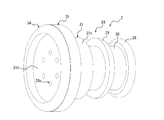
- FIG. 6 is an exploded perspective view of the cap shown in FIG. 5.
- FIG. 8 is an exploded perspective view of the cap viewed from an angle different from FIG. 7. It is a side view of the connector with a cap shown in FIG.
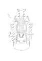
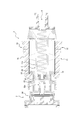
- FIG. 9 It is sectional drawing of the connector with a cap shown in FIG. It is a side view which shows the state when it changes from the 1st engagement state shown in FIG. 9 to a 2nd engagement state. It is sectional drawing of the connector with a cap shown in FIG. It is sectional drawing which shows the state when priming is complete
- the connector with a cap 1 includes a connector 2 and a cap 3 (that is, a cap according to this embodiment).
- the connector 2 has a connecting portion 5 (see FIG. 3 etc.) provided in the liquid flow path 4.
- the cap 3 is used for priming the liquid flow path 4.
- the liquid flow path 4 is for supplying a liquid to a human body in the present embodiment as described later.
- the liquid flow path 4 may be for supplying the liquid to a living body other than the human body.
- the connector 1 with a cap is provided in the infusion line 6. Therefore, the liquid flow path 4 is configured as the liquid flow path 4 in the infusion line 6.
- the connector 1 with a cap is not limited to the one provided in the infusion line 6, and may be provided, for example, in the spout of a syringe.
- the liquid channel 4 is configured as the liquid channel 4 in the syringe.
- the infusion line 6 shown in FIG. 1 is connected to a main infusion line (not shown) that administers a liquid such as a drug solution to a patient, and is used to co-inject an anticancer agent into the main infusion line.
- the infusion line 6 is provided at an infusion bag 7 containing a prepared anticancer drug, a medical tube 9 connected to the infusion bag 7 via an infusion bag connector 8, and a distal end of the tube 9. It has a connector 1 with a cap.
- a mixed injection part is provided in the middle of the main infusion line, and by connecting the connection part 5 of the connector 2 of the infusion line 6 to this mixed injection part, the anticancer drug is mixedly injected into the main infusion line from the infusion line 6. be able to.
- the liquid flow path 4 of the infusion line 6 is composed of the flow path in the infusion bag connector 8, the flow path in the tube 9, and the flow path in the connector 2.
- Reference numeral 10 indicates a fixed clamp that opens the fluid channel 4 when the anticancer drug is administered from the infusion line 6.
- the air in the liquid passage 4 of the infusion line 6 is prevented. Is replaced with an anti-cancer drug. Priming can be performed easily and safely by using the connector with a cap 1 located at the distal end of the liquid flow path 4 of the infusion line 6.
- the connector 2 has a cylindrical base portion 11 that forms a flow passage therein.
- the base 11 has an axis extending from the proximal end toward the distal end.
- the base portion 11 is a tubular tube connecting portion 11a connected to the distal end of the tube 9 (see FIG. 1) by an appropriate means, and is integrally connected to the distal end of the tube connecting portion 11a and is connected to the tube connecting portion 11a. It is composed of a hollow disk-shaped base body 11b having an expanded outer diameter, and a connecting cylinder 11c which is integrally connected to the distal end of the base body 11b and has an outer diameter reduced from the base body 11b. .
- connection cylinder 11c has a cylindrical shape with a reduced inner diameter at the distal end. That is, a ring-shaped reduced diameter portion 11d that protrudes inward in the radial direction is provided at the distal end of the connection cylinder 11c.
- the connecting cylinder 11c is closed by the valve body 12.
- the valve body 12 includes a valve body head portion 13 and an elastic portion 14 that biases the valve body head portion 13 toward the distal end side.
- the valve head 13 has a cylindrical peripheral wall 13a, a ceiling wall 13b that closes the distal end of the peripheral wall 13a, and a flange 13c that projects radially outward from the proximal end of the peripheral wall 13a. .
- the peripheral wall 13a is provided with a through hole 13d through which the liquid can pass.
- the through hole 13d is composed of two through holes. The number of through holes forming the through hole 13d can be appropriately increased or decreased.
- the through hole 13d is closed by the inner peripheral surface of the reduced diameter portion 11d provided at the distal end of the connection cylinder 11c.
- the flange 13c is in contact with the proximal end surface of the reduced diameter portion 11d.
- the elastic portion 14 is composed of a coil spring.
- the elastic portion 14 has its proximal end abutting on the distal end of the tube connecting portion 11 a, and its distal end abutting on the proximal end of the valve head 13.
- the valve body 12 can open the connecting cylinder 11c by pushing the valve body head 13 toward the proximal end side against the biasing force of the elastic portion 14.
- the elastic portion 14 is not limited to a coil spring and may be, for example, a bellows-like portion integrally connected to the valve head 13.
- the connection portion 5 of the connector 2 is composed of the connection cylinder 11c and the valve body 12.
- the connector 2 is configured as a closed connector in which the connecting portion 5 can be opened and closed.
- the outer peripheral wall 16 includes a pair of engagement pieces 15, an outer peripheral wall body 16a, and hinges 17 that swingably connect the pair of engagement pieces 15 to the outer peripheral wall body 16a.
- the hinges 17 each include a first portion 17a extending from the engagement piece 15 to one end side in the circumferential direction of the outer peripheral wall 16 and a second portion 17a extending from the engagement piece 15 to the other end side in the circumferential direction of the outer peripheral wall 16. 17b and.
- the outer peripheral wall 16 is provided concentrically with the connecting cylinder 11c.
- the pair of engagement pieces 15 are opposed to each other with the connection tube 11c interposed therebetween.
- the number of engaging pieces 15 can be increased or decreased as appropriate.
- the pair of engaging pieces 15 are connected to the connecting portion 5 via the hinge 17, the outer peripheral wall body 16a, and the base body 11b, respectively.
- Each of the pair of engagement pieces 15 can swing around the hinge 17. In this way, the pair of engaging pieces 15 are swingably connected to the connecting portion 5, respectively.
- the pair of engaging pieces 15 each have an engaging portion 18 formed of a convex portion on the inner peripheral surface at the distal end thereof. Further, each of the pair of engagement pieces 15 has an operation portion 19 on the outer peripheral surface of the portion on the proximal end side of the hinge 17.
- the operation portions 19 of the pair of engagement pieces 15 are each configured by a convex portion provided on the outer peripheral surface of the engagement piece 15. More specifically, each of the pair of operating portions 19 is composed of three ribs extending in the circumferential direction of the outer peripheral wall 16. On the outer peripheral surfaces of the pair of engaging pieces 15, one reinforcing rib 20 extending in the radial direction of the outer peripheral wall 16 is provided. Each of the pair of reinforcing ribs 20 extends from the distal end of the engagement piece 15 to the distal end of the operating portion 19.
- the pair of engaging pieces 15 are configured such that the engaging portions 18 move radially outward of the outer peripheral wall 16 around the hinge 17 when the operating portion 19 receives a pressing operation directed radially inward of the outer peripheral wall 16. Can be rocked to.
- the housing of the connector 2 (a portion excluding the valve body 12) is provided at three members integrated by appropriate fixing means, that is, at the distal end of the connecting cylinder 11c.
- the first member 21 composed of the reduced diameter portion 11d
- the second member 22 composed of a part of the base body 11b and the tube connecting part 11a
- the third member 23 composed of the other parts. It is configured.
- the number of members forming the housing of the connector 2 can be changed appropriately.
- the first member 21, the second member 22, and the third member 23 may be made of synthetic resin, for example.
- the first member 21 may be made of rubber or elastomer.
- the valve body head 13 may be made of synthetic resin, for example.
- the elastic portion 14 of the valve body 12 may be made of metal or synthetic resin, for example.
- the cap 3 has a housing 24 and a filter 25.
- the housing 24 has a connection port 26a, a lumen 26b, and a discharge port 26c.
- the housing 24 is formed with a fluid flow path 26 that extends from the connection port 26a to the discharge port 26c via the inner cavity 26b.
- the connection port 26a is composed of two through holes.
- the discharge port 26c is composed of six through holes. The number of through holes forming the connection port 26a and the discharge port 26c can be appropriately increased or decreased.
- the connection port 26a and the discharge port 26c are not limited to those configured by through holes.
- the filter 25 is made of a material having a function of allowing gas to pass therethrough and not allowing liquid to pass therethrough, and is provided in the channel 26 so as to cover the cross section of the channel 26. Therefore, when a fluid composed of a liquid and a gas flows into the flow path 26, the liquid in the fluid is blocked by the filter 25, while the gas in the fluid passes through the filter 25 and is discharged to the outside from the discharge port 26c. To be done.
- the filter 25 is arranged in the inner cavity 26b in the present embodiment, if the filter 25 is provided in the flow path 26, for example, in the discharge port 26c (that is, so as to cover the discharge port 26c from the outside of the housing 24). It may be arranged.
- the filter 25 may be a film whose surface is hydrophobized or a hydrophobic film (hydrophobic film).
- hydrophobic film examples include polytetrafluoroethylene (PTFE), a copolymer of tetrafluoroethylene and hexafluoropropylene (FEP), and a copolymer of tetrafluoroethylene and perfluoroalkyl vinyl ether ( PFA), polyvinylidene fluoride (PVDF), or the like can be used.
- PTFE polytetrafluoroethylene
- FEP hexafluoropropylene
- PFA perfluoroalkyl vinyl ether
- PVDF polyvinylidene fluoride
- the filter 25 those obtained by making these materials porous by a drawing method, a micro phase separation method, an electron beam etching method, a sintering method, an argon plasma particle or the like are preferably used.
- the method of hydrophobizing treatment is not particularly limited, and for example, a method of coating the surface of the filter 25 with a hydrophobic constituent material or the like can be used.
- the filter 25 is not limited to the one having the above-described configuration as long as it has a function of allowing gas to pass and not allowing liquid to pass, and, for example, a material such as a hydrophilic film may be used.
- the housing 24 has a connection port 26a and an insertion tube 27 that can be inserted into the connection tube 11c to connect the connection port 26a to the connection portion 5 of the connector 2.
- the connection port 26a is connected to the connection part 5 so that the fluid (liquid and gas) can flow into the connection port 26a from the connection part 5.
- the insertion tube 27 has a cylindrical shape with a closed proximal end, and has a connection port 26a on its outer peripheral surface. The outer peripheral surface of the insertion cylinder 27 can be in close contact with the inner peripheral surface of the reduced diameter portion 11d of the connection cylinder 11c.
- connection port 26a is reduced in diameter. It can be made to enter to a position beyond 11d and communicate with the flow path inside the connecting cylinder 11c. By this communication, the fluid located at the proximal end of the connection cylinder 11c can flow into the connection port 26a through the through hole 13d of the valve body head 13.
- the housing 24 has a connector so that the cap 3 is attached to the connector 2 when the connection port 26 a of the cap 3 and the connection portion 5 of the connector 2 are not connected.
- the first engagement portion 28 is engageable with the second engagement portion 18 of the engagement piece 15 in the present embodiment.
- the housing 24 holds the attachment state in which the cap 3 is attached to the connector 2 in the connection state between the connection port 26a of the cap 3 and the connection portion 5 of the connector 2. It has the 2nd engaging part 29 which can be engaged with connector 2 (engaging part 18 of engaging piece 15 in this embodiment).
- the housing 24 surrounds the connection portion 5 in the attached state in which the cap 3 is attached to the connector 2 in a non-connected state between the connection port 26 a of the cap 3 and the connection portion 5 of the connector 2. It has a tube 30.
- the first engaging portion 28 and the second engaging portion 29 are arranged side by side in the axial direction of the surrounding cylinder 30.
- the first engaging portion 28 and the second engaging portion 29 are provided on the outer peripheral surface of the surrounding cylinder 30, respectively.
- the first engaging portion 28 and the second engaging portion 29 are each configured by a convex portion.
- the surrounding cylinder 30 has a cylindrical shape that is concentric with the insertion cylinder 27.
- the first engaging portion 28 and the second engaging portion 29 are each configured by an annular convex portion provided over the entire circumference of the surrounding cylinder 30.
- the housing 24 has a hollow disk-shaped housing body 31.
- the housing body 31 has an axis extending from the proximal end to the distal end. Further, the housing body 31 is provided concentrically with the insertion cylinder 27 and the surrounding cylinder 30.
- the distal end of the insertion cylinder 27 and the distal end of the surrounding cylinder 30 are respectively provided in the disk-shaped first end wall 31a located at the proximal end of the housing body 31 and having a through hole in the center thereof. They are connected together. Further, the hollow portion of the insertion cylinder 27 communicates with the hollow portion of the housing body 31 via a through hole at the center of the first end wall 31a.
- the hollow portion of the insertion cylinder 27, the through hole at the center of the first end wall 31a, and the hollow portion of the housing body 31 form the inner cavity 26b.
- the disk-shaped second end wall 31b located at the distal end of the housing body 31 has six through holes that form the discharge port 26c at equal intervals in the circumferential direction around the axis of the housing body 31. It is provided.
- the outer peripheral edge of the first end wall 31a and the outer peripheral edge of the second end wall 31b are integrally connected by a cylindrical wall 31c.
- an enlarged diameter portion 31d is provided at an axially intermediate portion thereof.
- the outer peripheral edge of the proximal end surface of the filter 25 is fixed to an annular end surface located at the proximal end of the expanded diameter portion 31d by an appropriate means.
- the filter 25 may be fixed to the annular end surface located at the distal end of the expanded diameter portion 31d.
- the filter 25 may be sandwiched between an annular end surface located at the proximal end of the expanded diameter portion 31d and an annular end surface located on the distal side of the first end wall 31a.
- the inner surface of the first end wall 31a is provided with six first end ribs 31e extending radially from the axis of the housing body 31.
- Each of the six first end ribs 31e has a distal end surface capable of supporting the filter 25 when the filter 25 is bent toward the proximal end side.
- the inner surface of the second end wall 31b is provided with six second end ribs 31f extending radially from the axial center of the housing body 31.
- Each of the six second end ribs 31f has a proximal end surface capable of supporting the filter 25 when the filter 25 is bent toward the distal end side.
- the six second end ribs 31f are integrally connected to each other at the shaft center of the housing body 31.
- one through hole that configures the discharge port 26c is arranged between the second end ribs 31f adjacent to each other in the circumferential direction.
- the six second end ribs 31f and the six first end ribs 31e are arranged side by side in the axial direction of the housing body 31.
- Six first end ribs 31e and two second end ribs 31f are provided in accordance with the number of through holes that configure the discharge port 26c, but these numbers are the same as the number of through holes that configure the discharge port 26c. It can be increased or decreased as appropriate.
- the first end rib 31e and the second end rib 31f may not be provided.
- a flange wall 32 extending outward in the radial direction is integrally connected to the outer peripheral edge at the distal end of the housing body 31.
- the flange wall 32 has an annular shape, and a cylindrical outer wall 33 extending to the distal end side is integrally connected to the outer peripheral edge of the flange wall 32.
- the flange wall 32 has an outer diameter larger than the inner peripheral surface of the distal end of the outer peripheral wall body 16a having a cylindrical shape.
- the cylindrical wall 31c of the housing body 31 is configured to be surrounded by the distal end of the outer peripheral wall body 16a in the connected state of the connection port 26a of the cap 3 and the connection portion 5 of the connector 2.
- the housing 24 is made up of two members integrated by appropriate fixing means, that is, a part of the cylindrical wall 31c, a part of the flange wall 32 and the outer wall 33.
- first member 34 and a second member 35 of the other parts are changed as appropriate.
- the number of members forming the housing 24 can be changed as appropriate.
- Each of the first member 34 and the second member 35 can be formed by injection molding of synthetic resin.
- the materials and molding methods of the first member 34 and the second member 35 can be changed as appropriate.
- the connector with a cap 1 has the cap 3 in the housing 24 of the cap 3 when the connection port 26 a of the cap 3 and the connection portion 5 of the connector 2 are not connected.
- a first engaging portion 28 engageable with the connector 2 is provided so as to maintain the attached state of the connector attached to the connector 2. Therefore, since the attachment state of the cap 3 to the connector 2 can be maintained via the first engaging portion 28 before the priming of the liquid flow path 4 is performed, the cap 3 is performed when the priming of the liquid flow path 4 is performed. Since it is not necessary to attach the connector to the connector 2, priming can be performed by a simple operation.
- the connector 1 with a cap has the cap 3 in the housing 24 of the cap 3 when the connection port 26 a of the cap 3 and the connection portion 5 of the connector 2 are connected. It has the 2nd engaging part 29 which can be engaged with connector 2 so that the attachment state attached to connector 2 may be maintained. Therefore, when the liquid channel 4 is being primed, the state of attachment of the cap 3 to the connector 2 can be maintained via the second engaging portion 29, and thus the priming can be performed by a simple operation. it can.
- the connector 2 is provided with the engagement piece 15, the engagement piece 15 is provided with the engagement portion 18, and the engagement portion 15 is rocked with respect to the connection portion 5 to thereby engage the engagement portion 15.
- the engagement between 18 and the second engaging portion 29 can be released. Therefore, after the priming of the liquid flow path 4 is completed, the engagement between the engagement portion 18 and the second engagement portion 29 is released, and the cap 3 is detached from the connector 2 as shown in FIG. Can be connected to a desired flow path.
- the connector 1 with a cap according to the present embodiment has an operating portion 19 on the engaging piece 15. Therefore, after the priming of the liquid flow path 4 is completed, the engagement between the engagement portion 18 and the second engagement portion 29 can be easily released by operating the operation portion 19.
- the engaging portion 18 of the engaging piece 15 can engage with the first engaging portion 28. Therefore, it is possible to realize a simple configuration in which the engaging portion 18 that can be engaged with the second engaging portion 29 is also used for engaging with the first engaging portion 28.
- the housing 24 of the cap 3 is provided with the envelope 30. Therefore, when the cap 3 is attached to the connector 2 when the connection port 26a of the cap 3 and the connection portion 5 of the connector 2 are not connected, the connection portion 5 is surrounded by the enclosing tube 30 and the connection portion 5 is formed. It is possible to suppress adhesion of contaminants and the like to the.
- the connector 1 with a cap according to the present embodiment is provided with the first engaging portion 28 and the second engaging portion 29 in the surrounding cylinder 30 of the cap 3, a simple configuration can be realized.
- the connector 1 with a cap according to the present embodiment is provided with the first engaging portion 28 and the second engaging portion 29 on the outer peripheral surface of the enclosing cylinder 30 of the cap 3, a simple configuration can be realized. .
- the connector 1 with a cap according to the present embodiment can realize a simple configuration because the first engaging portion 28 of the cap 3 is formed by the convex portion.
- the connector 1 with a cap according to the present embodiment is provided with the connection tube 11c at the connection portion 5 of the connector 2, and the housing 24 of the cap 3 is provided with the insertion tube 27 having the connection port 26a. Therefore, it is possible to realize a simple configuration in which the connection port 26a of the cap 3 can be stably connected to the connection portion 5 of the connector 2.
- the cap 3 may have a structure in which the rotation blocking portion 36 is provided in the housing 24 as shown in FIG.
- FIG. 14 is a perspective view showing a modified example of the connector with cap 1.
- the rotation blocking portion 36 has the axis of the surrounding cylinder 30 in the attached state in which the cap 3 is attached to the connector 2 when the connection port 26a of the cap 3 and the connection portion 5 of the connector 2 are not connected. It can be engaged with the connector 2 so as to prevent rotation of the housing 24 (more specifically, the first engaging portion 28) with respect to the connector 2 that is the center. With such a configuration, it is not necessary to provide the first engaging portion 28 around the entire circumference of the housing 24.
- the rotation blocking portion 36 is provided on the outer peripheral surface of the envelope cylinder 30.
- the rotation blocking portion 36 is composed of a step portion that can come into contact with both ends in the circumferential direction of the engaging portions 18 of the pair of engaging pieces 15 provided in the connector 2.
- the housing 24 is provided with another rotation blocking portion 37.
- the rotation blocking portion 37 is attached to the connector 2 around the shaft center of the surrounding cylinder 30 when the cap 3 is attached to the connector 2 in the connected state of the connection port 26a of the cap 3 and the connection portion 5 of the connector 2. It can be engaged with the connector 2 so as to prevent the rotation of the housing 24 (more specifically, the second engaging portion 29). With such a configuration, it is not necessary to provide the second engaging portion 29 over the entire circumference of the housing 24.
- the rotation blocking portion 37 is provided on the outer peripheral surface of the surrounding cylinder 30.
- the rotation blocking portion 37 is composed of a step portion that can come into contact with both ends in the circumferential direction of the engaging portions 18 of the pair of engaging pieces 15 provided in the connector 2.
- the method of using the connector with a cap has a connecting step S1, a priming step S2, and a removing step S3.
- connection step S1 is performed.
- the connecting step S1 is performed by the first operation so that the cap 3 is attached to the connector 2 in the unconnected state between the connection port 26a of the cap 3 and the connecting portion 5 of the connector 2 as shown in FIG. From the first engaged state in which the mating portion 28 is engaged with the connector 2 (the engaging portion 18 of the engaging piece 15 in the present embodiment), the connection port 26a of the cap 3 is connected to the connector 2 as shown in FIG. This is the step of bringing the unit 5 into the connected state. More specifically, in the connecting step S1, the cap 3 is attached to the connector 2 in the connected state in which the connection port 26a of the cap 3 is connected to the connecting portion 5 of the connector 2 from the first engagement state. The second engagement portion 29 is brought into a second engagement state in which the second engagement portion 29 is engaged with the connector 2 (the engagement portion 18 of the engagement piece 15 in the present embodiment) so as to hold.
- the cap 3 in the connecting step S1, the cap 3 is brought into the second engagement state from the first engagement state by pressing the cap 3 straight toward the connector 2 without twisting.
- the engagement portions 18 of the pair of engagement pieces 15 are pressed against the second engagement portions 29 from the proximal end side toward the distal end side along the axial direction of the enclosing tube 30, respectively.
- the pair of engaging pieces 15 can be swung so that the joining portion 18 moves outward in the radial direction, and the second engaging portion 29 can be overcome.
- the distal end surfaces of the engaging portions 18 of the pair of engaging pieces 15 are provided with inclined surfaces for causing such overcoming.
- an inclined surface may be provided on the proximal end faces of the second engaging portions 29 instead of or in addition to the distal end faces of the engaging portions 18 of the pair of engaging pieces 15. .
- the engagement portions 18 of the pair of engagement pieces 15 are pushed.
- the second engaging portion 29 can be engaged to bring the second engaging state.
- a priming step S2 is performed after the connection step S1.
- the connection state in which the connection port 26a of the cap 3 is connected to the connection portion 5 of the connector 2 (in the present embodiment, until the priming of the liquid flow path 4 is completed). (2 engaged state) is held.
- the gas flowing into the inner cavity 26b from the connection port 26a passes through the filter 25 and is discharged to the outside from the discharge port 26c.
- gas is discharged from the liquid flow path 4 and reaches the connection port 26a and flows into the inner cavity 26b, the liquid cannot pass through the filter 25 and is blocked by the filter 25. In this way, the priming of the liquid flow path 4 is completed.
- the removing step S3 is performed after the priming step S2.
- the cap 3 is removed from the connector 2 from the connection state where the connection port 26a of the cap 3 is connected to the connection portion 5 of the connector 2. More specifically, in the detaching step S3, the engagement between the second engagement portion 29 and the connector 2 (the engagement portion 18 of the engagement piece 15 in this embodiment) is released from the second engagement state. Then, the cap 3 is removed from the connector 2. At this time, the operation of pressing the operation portion 19 of the engagement piece 15 inward in the radial direction moves the engagement portion 18 of the engagement piece 15 outward in the radial direction, and the engagement portion 18 and the second engagement portion 29. The engagement with can be easily released.
- the connecting step S1 is performed from the first engagement state. Therefore, when priming the liquid flow path 4, the cap 3 is newly attached to the connector 2. Since the labor for mounting can be saved, priming can be performed by a simple operation.
Landscapes
- Health & Medical Sciences (AREA)
- Heart & Thoracic Surgery (AREA)
- Pulmonology (AREA)
- Engineering & Computer Science (AREA)
- Anesthesiology (AREA)
- Biomedical Technology (AREA)
- Hematology (AREA)
- Life Sciences & Earth Sciences (AREA)
- Animal Behavior & Ethology (AREA)
- General Health & Medical Sciences (AREA)
- Public Health (AREA)
- Veterinary Medicine (AREA)
- Infusion, Injection, And Reservoir Apparatuses (AREA)
Abstract
キャップ付きコネクタは、液体流路に設けられた接続部を備えるコネクタと、前記液体流路のプライミングのためのキャップと、を有し、前記キャップは、前記接続部に接続可能な接続口から内腔を介して排出口まで連なる流路を形成するハウジングと、前記流路に設けられるとともに気体を透過させ且つ液体を透過させないフィルタと、を有し、前記ハウジングは、前記接続口と前記接続部との非接続状態において前記キャップが前記コネクタに取付けられた取付け状態を保持するように前記コネクタと係合可能な第1係合部を有する。
Description
本開示は、キャップ付きコネクタ、キャップ、及びキャップ付きコネクタの使用方法に関する。
従来から、薬液等の液体を医療用のチューブを通して体内へ送るようにした輸液ラインに他の輸液ラインを接続して、メインの輸液ラインを流れる液体に抗がん剤等の他の液体を混注することが行われている。この場合、他の輸液ラインの遠位端には接続部を有するコネクタが設けられ、この接続部をメインの輸液ラインの途中に設けられた混注部に接続することで、他の輸液ラインはメインの輸液ラインに接続される。
メインの輸液ラインに他の輸液ラインを接続する際には、他の輸液ラインのチューブ内の空気が患者の体内へ送られることを防止するために、当該接続の前にチューブ内の空気を液体に置換するプライミングが行われる。プライミングには種々の方法があるが、他の輸液ラインの遠位端に設けられるコネクタにプライミング用のキャップを接続し、このキャップを通じて液体流路内の空気のみを外部に排出し、液体流路内を液体で満たすようにした技術が開発されている。
このようなキャップとして、例えば特許文献1には、コネクタの接続部に接続可能な接続口から内腔を介して排出口まで連なる流路を形成するハウジングと、上記流路に設けられるとともに気体を透過させ且つ液体を透過させないフィルタと、を有するものが記載されている。このキャップのハウジングの外周面には、円環状の段部が設けられており、コネクタには、キャップがコネクタに取付けられた取付け状態を保持するように上記段部と係合可能な係合片が設けられている。コネクタの係合片がキャップの段部と係合するようにキャップをコネクタに取付けると、その取付けに伴ってキャップのハウジングの接続口がコネクタの接続部に接続され、その接続状態が保持される。この状態でチューブ内の空気が接続口を介してキャップの流路に流入すると、フィルタを通してこの空気を外部に排出することができる。そして、チューブ内の空気が全て排出されることによりプライミングが完了する。
特許文献1に記載されるようなキャップでは、プライミングを行う際にキャップを新たにコネクタに取付ける必要がある。しかし、より簡易な操作でプライミングを行うことができれば都合が良い。
本開示は、このような点に鑑み、簡易な操作でプライミングを行うことができる、キャップ付きコネクタ、キャップ、及びキャップ付きコネクタの使用方法を提供することを目的とする。
本発明の一態様としてのキャップ付きコネクタは、
液体流路に設けられた接続部を備えるコネクタと、
前記液体流路のプライミングのためのキャップと、を有し、
前記キャップは、
前記接続部に接続可能な接続口から内腔を介して排出口まで連なる流路を形成するハウジングと、
前記流路に設けられるとともに気体を透過させ且つ液体を透過させないフィルタと、を有し、
前記ハウジングは、前記接続口と前記接続部との非接続状態において前記キャップが前記コネクタに取付けられた取付け状態を保持するように前記コネクタと係合可能な第1係合部を有する。
液体流路に設けられた接続部を備えるコネクタと、
前記液体流路のプライミングのためのキャップと、を有し、
前記キャップは、
前記接続部に接続可能な接続口から内腔を介して排出口まで連なる流路を形成するハウジングと、
前記流路に設けられるとともに気体を透過させ且つ液体を透過させないフィルタと、を有し、
前記ハウジングは、前記接続口と前記接続部との非接続状態において前記キャップが前記コネクタに取付けられた取付け状態を保持するように前記コネクタと係合可能な第1係合部を有する。
本発明の1つの実施形態として、前記ハウジングは、前記接続口と前記接続部との接続状態において前記取付け状態を保持するように前記コネクタと係合可能な第2係合部を有する。
本発明の1つの実施形態として、
前記コネクタは、前記接続部に揺動可能に連結する係合片を有し、
前記係合片は、前記接続状態において前記取付け状態を保持するように前記第2係合部と係合可能な係合部を有するとともに、前記接続部に対する揺動によって前記係合部と前記第2係合部との係合を解除可能である。
前記コネクタは、前記接続部に揺動可能に連結する係合片を有し、
前記係合片は、前記接続状態において前記取付け状態を保持するように前記第2係合部と係合可能な係合部を有するとともに、前記接続部に対する揺動によって前記係合部と前記第2係合部との係合を解除可能である。
本発明の1つの実施形態として、前記係合片は、前記係合部と前記第2係合部との係合を解除するための操作を受ける操作部を有する。
本発明の1つの実施形態として、前記係合片の前記係合部は、前記非接続状態において前記取付け状態を保持するように前記第1係合部と係合可能である。
本発明の1つの実施形態として、前記ハウジングは、前記非接続状態における前記取付け状態において前記接続部を包囲する包囲筒を有する。
本発明の1つの実施形態として、前記第1係合部は、前記包囲筒に設けられている。
本発明の1つの実施形態として、前記第1係合部は、前記包囲筒の外周面に設けられている。
本発明の1つの実施形態として、前記第1係合部は、凸部で構成されている。
本発明の1つの実施形態として、前記ハウジングは、前記非接続状態における前記取付け状態において前記包囲筒の軸心を中心とする前記コネクタに対する前記ハウジングの回転を阻止するように前記コネクタと係合可能な回転阻止部を有する。
本発明の1つの実施形態として、
前記接続部は、接続筒を有し、
前記ハウジングは、前記接続口を備えるとともに前記接続口を前記接続部に接続するために前記接続筒に挿入可能な挿入筒を有する。
前記接続部は、接続筒を有し、
前記ハウジングは、前記接続口を備えるとともに前記接続口を前記接続部に接続するために前記接続筒に挿入可能な挿入筒を有する。
本発明の一態様としてのキャップは、
液体流路のプライミングのために、前記液体流路に設けられた接続部を備えるコネクタに取付けられるキャップであって、
前記接続部に接続可能な接続口から内腔を介して排出口まで連なる流路を形成するハウジングと、
前記流路に設けられるとともに気体を透過させ且つ液体を透過させないフィルタと、を有し、
前記ハウジングは、
前記接続口と前記接続部との非接続状態において前記キャップが前記コネクタに取付けられた取付け状態を保持するように前記コネクタと係合可能な第1係合部と、
前記接続口と前記接続部との接続状態において前記取付け状態を保持するように前記コネクタと係合可能な第2係合部と、を有する。
液体流路のプライミングのために、前記液体流路に設けられた接続部を備えるコネクタに取付けられるキャップであって、
前記接続部に接続可能な接続口から内腔を介して排出口まで連なる流路を形成するハウジングと、
前記流路に設けられるとともに気体を透過させ且つ液体を透過させないフィルタと、を有し、
前記ハウジングは、
前記接続口と前記接続部との非接続状態において前記キャップが前記コネクタに取付けられた取付け状態を保持するように前記コネクタと係合可能な第1係合部と、
前記接続口と前記接続部との接続状態において前記取付け状態を保持するように前記コネクタと係合可能な第2係合部と、を有する。
本発明の1つの実施形態として、
前記ハウジングは、前記非接続状態における前記取付け状態において前記接続部を包囲する包囲筒を有し、
前記第1係合部及び前記第2係合部は、前記包囲筒の軸方向に並べて配置されている。
前記ハウジングは、前記非接続状態における前記取付け状態において前記接続部を包囲する包囲筒を有し、
前記第1係合部及び前記第2係合部は、前記包囲筒の軸方向に並べて配置されている。
本発明の1つの実施形態として、前記第1係合部及び前記第2係合部は、それぞれ、前記包囲筒の外周面に設けられている。
本発明の1つの実施形態として、前記第1係合部及び前記第2係合部は、それぞれ、凸部で構成されている。
本発明の1つの実施形態として、前記ハウジングは、前記非接続状態における前記取付け状態において前記包囲筒の軸心を中心とする前記コネクタに対する前記ハウジングの回転を阻止するように前記コネクタと係合可能な回転阻止部を有する。
本発明の一態様としてのキャップ付きコネクタの使用方法は、
液体流路に設けられた接続部を備えるコネクタと、
前記液体流路のプライミングのためのキャップと、を有し、
前記キャップは、
前記接続部に接続可能な接続口から内腔を介して排出口まで連なる流路を形成するハウジングと、
前記流路に設けられるとともに気体を透過させ且つ液体を透過させないフィルタと、を有し、
前記ハウジングは、前記接続口と前記接続部との非接続状態において前記キャップが前記コネクタに取付けられた取付け状態を保持するように前記コネクタと係合可能な第1係合部を有する、
キャップ付きコネクタの使用方法であって、
前記非接続状態において前記取付け状態を保持するように前記第1係合部が前記コネクタと係合した第1係合状態から、前記接続口と前記接続部との接続状態にする接続ステップと、
前記液体流路のプライミングが終了するまで前記接続状態を保持するプライミングステップと、
前記接続状態から前記キャップを前記コネクタから取外す取外しステップと、を有する。
液体流路に設けられた接続部を備えるコネクタと、
前記液体流路のプライミングのためのキャップと、を有し、
前記キャップは、
前記接続部に接続可能な接続口から内腔を介して排出口まで連なる流路を形成するハウジングと、
前記流路に設けられるとともに気体を透過させ且つ液体を透過させないフィルタと、を有し、
前記ハウジングは、前記接続口と前記接続部との非接続状態において前記キャップが前記コネクタに取付けられた取付け状態を保持するように前記コネクタと係合可能な第1係合部を有する、
キャップ付きコネクタの使用方法であって、
前記非接続状態において前記取付け状態を保持するように前記第1係合部が前記コネクタと係合した第1係合状態から、前記接続口と前記接続部との接続状態にする接続ステップと、
前記液体流路のプライミングが終了するまで前記接続状態を保持するプライミングステップと、
前記接続状態から前記キャップを前記コネクタから取外す取外しステップと、を有する。
本開示によれば、簡易な操作でプライミングを行うことができる、キャップ付きコネクタ、キャップ、及びキャップ付きコネクタの使用方法を提供することができる。
以下、図面を参照して、本発明の一実施形態に係るキャップ付きコネクタ、キャップ、及びキャップ付きコネクタの使用方法について、詳細に例示説明する。
まず、本発明の一実施形態に係るキャップ付きコネクタ及びキャップについて、詳細に例示説明する。
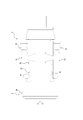
図1に示すように、本実施形態に係るキャップ付きコネクタ1は、コネクタ2とキャップ3(すなわち、本実施形態に係るキャップ)とを有している。コネクタ2は、液体流路4に設けられた接続部5(図3等参照)を有している。キャップ3は、液体流路4のプライミングのために用いられる。液体流路4は、本実施形態では後述するように人体に液体を供給するためのものである。しかし、液体流路4は、人体以外の生体に液体を供給するためのものであってもよい。
図1に示すように、本実施形態では、キャップ付きコネクタ1は、輸液ライン6に設けられている。したがって、液体流路4は、輸液ライン6における液体流路4として構成されている。しかし、キャップ付きコネクタ1は、輸液ライン6に設けられるものに限らず、例えば、シリンジの注出口に設けられてもよい。この場合、液体流路4は、シリンジにおける液体流路4として構成される。
図1に示す輸液ライン6は、患者に薬液等の液体を投与するメインの輸液ライン(不図示)に接続されて、メインの輸液ラインに抗がん剤を混注するためのものである。輸液ライン6は、調剤済みの抗がん剤を収容する輸液バッグ7、輸液バッグ7に輸液バッグ用コネクタ8を介して接続される医療用のチューブ9、及びチューブ9の遠位端に設けられたキャップ付きコネクタ1を有している。メインの輸液ラインの途中には混注部が設けられ、この混注部に輸液ライン6のコネクタ2の接続部5を接続することにより、輸液ライン6から抗がん剤をメインの輸液ラインに混注することができる。このように、輸液ライン6の液体流路4は、輸液バッグ用コネクタ8内の流路と、チューブ9内の流路と、コネクタ2内の流路と、で構成されている。なお、符号10は、輸液ライン6から抗がん剤を投与するときに流体流路4を開放する固定式のクレンメを示している。
輸液ライン6をメインの輸液ラインに接続する前に、輸液ライン6の液体流路4内の空気が患者の体内へ送られることを防止するために、輸液ライン6の液体流路4内の空気を抗がん剤に置換するプライミングが行われる。プライミングは輸液ライン6の液体流路4の遠位端に位置するキャップ付きコネクタ1を用いることにより、容易かつ安全に行うことができる。
図2、図3に示すように、コネクタ2は、内部に流路を形成する筒状の基部11を有している。基部11は、近位端から遠位端に向かう軸心を有している。基部11は、チューブ9(図1参照)の遠位端に適宜の手段で接続された筒状のチューブ接続部11aと、チューブ接続部11aの遠位端に一体に連なるとともにチューブ接続部11aより拡径した外径を有する中空円板状の基部本体11bと、基部本体11bの遠位端に一体に連なるとともに基部本体11bより縮径した外径を有する接続筒11cと、で構成されている。接続筒11cは、遠位端において内径が縮径した円筒状をなしている。すなわち、接続筒11cの遠位端には、径方向内側に突出する円環状の縮径部11dが設けられている。
図3に示すように、接続筒11cは、弁体12によって閉塞されている。弁体12は、弁体頭部13と、弁体頭部13を遠位端側に付勢する弾性部14と、で構成されている。弁体頭部13は、筒状の周壁13aと、周壁13aの遠位端を閉塞する天壁13bと、周壁13aの近位端から径方向外側に突出するフランジ13cと、を有している。周壁13aには、液体が通過可能な貫通口13dが設けられている。貫通口13dは、2つの貫通孔で構成されている。貫通口13dを構成する貫通孔の数は適宜増減が可能である。貫通口13dは、接続筒11cの遠位端に設けられた縮径部11dの内周面によって閉塞されている。フランジ13cは、縮径部11dの近位端面に当接している。
弾性部14は、コイルばねで構成されている。弾性部14は、その近位端がチューブ接続部11aの遠位端に当接する一方、その遠位端が弁体頭部13の近位端に当接している。弁体12は、弁体頭部13が弾性部14の付勢力に抗して近位端側に押し込まれることで、図4に示すように、接続筒11cを開放することができる。弾性部14は、コイルばねで構成されるものに限らず、例えば、弁体頭部13に一体に連なる蛇腹状部で構成されてもよい。このように本実施形態では、コネクタ2の接続部5は、接続筒11cと弁体12とで構成されている。コネクタ2は、接続部5が開閉可能な閉鎖式コネクタとして構成されている。
図2、図3に示すように、コネクタ2の基部本体11bの遠位端における外周縁には、切り欠きによって一対の係合片15が形成された筒状の外周壁16の軸方向一端部が一体に連なっている。外周壁16は、一対の係合片15と、外周壁本体16aと、一対の係合片15をそれぞれ外周壁本体16aに揺動可能に連結するヒンジ17と、で構成されている。ヒンジ17は、それぞれ、係合片15から外周壁16の周方向一端側に延在する第1部分17aと、係合片15から外周壁16の周方向他端側に延在する第2部分17bと、で構成されている。外周壁16は接続筒11cと同心に設けられている。一対の係合片15は、接続筒11cを挟んで互いに対向している。しかし、係合片15の数は適宜増減が可能である。一対の係合片15は、それぞれ、ヒンジ17、外周壁本体16a及び基部本体11bを介して接続部5に連結されている。一対の係合片15は、それぞれ、ヒンジ17を中心として揺動可能である。このように、一対の係合片15は、それぞれ、接続部5に揺動可能に連結されている。
一対の係合片15は、それぞれ、その遠位端における内周面に凸部で構成された係合部18を有している。また、一対の係合片15は、それぞれ、ヒンジ17より近位端側の部分における外周面に操作部19を有している。一対の係合片15の操作部19は、それぞれ、係合片15の外周面に設けられた凸部で構成されている。より具体的に、一対の操作部19は、それぞれ、外周壁16の周方向に延在する3本のリブで構成されている。一対の係合片15の外周面には、それぞれ、外周壁16の径方向に延在する1本の補強用リブ20が設けられている。一対の補強用リブ20は、それぞれ、係合片15の遠位端から操作部19の遠位端まで延在している。
一対の係合片15は、操作部19が外周壁16の径方向内側に向かう押圧操作を受けることにより、ヒンジ17を中心に、係合部18が外周壁16の径方向外側に移動するように揺動することができる。
図3に示すように、本実施形態では、コネクタ2のハウジング(弁体12を除く部分)は、適宜の固着手段で一体化された3つの部材、すなわち、接続筒11cの遠位端に設けられた縮径部11dで構成される第1部材21と、基部本体11bの一部及びチューブ接続部11aで構成される第2部材22と、その他の部分で構成される第3部材23とで構成されている。しかし、コネクタ2のハウジングを構成する部材の数は、適宜変更が可能である。
第1部材21、第2部材22及び第3部材23は、例えば、合成樹脂製であってよい。第1部材21は、ゴム又はエラストマー製であってもよい。弁体頭部13は、例えば、合成樹脂製であってよい。弁体12の弾性部14は、例えば、金属又は合成樹脂製であってよい。
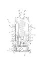
図5、図6に示すように、キャップ3は、ハウジング24とフィルタ25とを有している。ハウジング24は、接続口26aと、内腔26bと、排出口26cと、を有している。ハウジング24には、接続口26aから内腔26bを介して排出口26cまで連なる流体の流路26が形成されている。接続口26aは、本実施形態では、2つの貫通孔で構成されている。排出口26cは、本実施形態では、6つの貫通孔で構成されている。接続口26a及び排出口26cを構成する貫通孔の数は、適宜増減が可能である。接続口26a及び排出口26cは、貫通孔で構成されるものに限られない。
フィルタ25は、気体を透過させ且つ液体を透過させない機能を有する材質で形成され、流路26の断面を覆うように流路26に設けられている。したがって、液体と気体とで構成される流体が流路26に流入すると、流体中の液体はフィルタ25で堰き止められる一方、流体中の気体はフィルタ25を透過して排出口26cから外部に排出される。フィルタ25は、本実施形態では内腔26bに配置されているが、流路26に設けられていれば、例えば、排出口26cに(すなわち、排出口26cをハウジング24の外側から覆うように)配置されてもよい。
フィルタ25は、その表面が疎水化処理された膜、又は疎水性膜(疎水膜)であってよい。このような疎水性膜の構成材料としては、例えば、ポリテトラフルオロエチレン(PTFE)、テトラフルオロエチレンとヘキサフルオロプロピレンの共重合体(FEP)、テトラフルオロエチレンとパーフルオロアルキルビニルエーテルの共重合体(PFA)、ポリフッ化ビニリデン(PVDF)等を用いることができる。フィルタ25は、これらの材料を、延伸法、ミクロ相分離法、電子線エッチング法、焼結法、アルゴンプラズマ粒子等の方法で多孔質としたものが好適に用いられる。また、疎水化処理の方法は、特に限定されず、例えば、フィルタ25の表面に疎水性を有する構成材料をコーティングする方法等を用いることもできる。さらに、フィルタ25としては、気体を透過させ且つ液体を透過させない機能を有していれば上記構成のものに限らず、例えば親水性膜など他の材質のものを用いることもできる。
図6に示すように、ハウジング24は、接続口26aを備えるとともに接続口26aをコネクタ2の接続部5に接続するために接続筒11cに挿入可能な挿入筒27を有している。図12に示すように、挿入筒27を接続筒11cに挿入することにより、接続部5から流体(液体及び気体)が接続口26aに流入できるように接続口26aを接続部5に接続することができる。挿入筒27は、近位端が閉塞した円筒状をなしており、その外周面に接続口26aを有している。また、挿入筒27の外周面は、接続筒11cの縮径部11dの内周面に密接することができる。挿入筒27を接続筒11cに挿入することにより、挿入筒27の近位端で弁体頭部13を接続筒11cの遠位端から近位端側に押し込み、接続口26aを、縮径部11dを越える位置まで進入させて接続筒11cの内部の流路に連通させることができる。この連通により、接続筒11cの近位端に位置する流体は、弁体頭部13の貫通口13dを介して接続口26aに流入することができる。
図9、図10に示すように、ハウジング24は、キャップ3の接続口26aとコネクタ2の接続部5との非接続状態においてキャップ3がコネクタ2に取付けられた取付け状態を保持するようにコネクタ2(本実施形態では、係合片15の係合部18)と係合可能な第1係合部28を有している。また、ハウジング24は、図11、図12に示すように、キャップ3の接続口26aとコネクタ2の接続部5との接続状態においてキャップ3がコネクタ2に取付けられた取付け状態を保持するようにコネクタ2(本実施形態では、係合片15の係合部18)と係合可能な第2係合部29を有している。
図10に示すように、ハウジング24は、キャップ3の接続口26aとコネクタ2の接続部5との非接続状態における、キャップ3がコネクタ2に取付けられた取付け状態において接続部5を包囲する包囲筒30を有している。図5、図6に示すように、第1係合部28及び第2係合部29は、包囲筒30の軸方向に並べて配置されている。第1係合部28及び第2係合部29は、それぞれ、包囲筒30の外周面に設けられている。第1係合部28及び第2係合部29は、それぞれ、凸部で構成されている。本実施形態では、包囲筒30は挿入筒27と同心の円筒状をなしている。第1係合部28及び第2係合部29は、それぞれ、包囲筒30の全周に亘って設けられた円環状の凸部で構成されている。
図5、図6に示すように、ハウジング24は、中空円板状のハウジング本体31を有している。ハウジング本体31は、近位端から遠位端まで延在する軸心を有している。また、ハウジング本体31は、挿入筒27及び包囲筒30と同心に設けられている。ハウジング本体31の近位端に位置するとともに中央に貫通孔を有する円板状の第1端壁31aには、挿入筒27の遠位端と、包囲筒30の遠位端とが、それぞれ、一体に連結している。また、挿入筒27の中空部は、第1端壁31aの中央の貫通孔を介してハウジング本体31の中空部と連通している。したがって、挿入筒27の中空部と、第1端壁31aの中央の貫通孔と、ハウジング本体31の中空部とで内腔26bが構成されている。ハウジング本体31の遠位端に位置する円板状の第2端壁31bには、排出口26cを構成する6つの貫通孔が、ハウジング本体31の軸心を中心とする周方向に等間隔で設けられている。第1端壁31aの外周縁と第2端壁31bの外周縁とは、円筒状の筒壁31cによって一体に連結されている。筒壁31cの内周面には、その軸方向中間部に拡径部31dが設けられている。
拡径部31dの近位端に位置する円環状の端面には、フィルタ25の近位端面における外周縁が適宜の手段によって固着されている。しかし、フィルタ25は、拡径部31dの遠位端に位置する円環状の端面に固着されてもよい。フィルタ25を、拡径部31dの近位端に位置する円環状の端面と第1端壁31aよりも遠位側に位置する円環状の端面とで挟持する構成としてもよい。
図7に示すように、第1端壁31aの内面には、ハウジング本体31の軸心から放射状に延在する6つの第1端リブ31eが設けられている。6つの第1端リブ31eは、それぞれ、フィルタ25が近位端側に撓んだ際にフィルタ25を支持可能な遠位端面を有している。図8に示すように、第2端壁31bの内面には、ハウジング本体31の軸心から放射状に延在する6つの第2端リブ31fが設けられている。6つの第2端リブ31fは、それぞれ、フィルタ25が遠位端側に撓んだ際にフィルタ25を支持可能な近位端面を有している。6つの第2端リブ31fは、ハウジング本体31の軸心において互いに一体に連結している。図6に示すように、周方向に隣接する第2端リブ31fの間には、それぞれ、排出口26cを構成する1つの貫通孔が配置されている。6つの第2端リブ31fと6つの第1端リブ31eとは、ハウジング本体31の軸方向に並ぶように配置されている。第1端リブ31e及び第2端リブ31fは、排出口26cを構成する貫通孔の数に合わせて6つずつ設けられているが、これらの数は、排出口26cを構成する貫通孔の数に合わせて適宜増減が可能である。第1端リブ31e及び第2端リブ31fを設けない構成としてもよい。
図5、図6に示すように、ハウジング本体31の遠位端における外周縁には、径方向外側に延在するフランジ壁32が一体に連結している。フランジ壁32は円環状をなしており、その外周縁には、遠位端側に延在する円筒状の外壁33が一体に連結している。図12に示すように、フランジ壁32は、円筒状をなす外周壁本体16aの遠位端の内周面より大きい外径を有している。ハウジング本体31の筒壁31cは、キャップ3の接続口26aとコネクタ2の接続部5との接続状態において外周壁本体16aの遠位端に包囲されるように構成されている。
図6~図8に示すように、本実施形態では、ハウジング24は、適宜の固着手段で一体化された2つの部材、すなわち、筒壁31cの一部、フランジ壁32の一部及び外壁33の一部で構成される第1部材34と、その他の部分で構成される第2部材35とで構成されている。しかし、ハウジング24を構成する部材の数は、適宜変更が可能である。第1部材34及び第2部材35は、それぞれ、合成樹脂の射出成形によって形成することができる。しかし、第1部材34及び第2部材35の材料及び成形方法は適宜変更が可能である。
本実施形態に係るキャップ付きコネクタ1は、図9、図10に示されるように、キャップ3のハウジング24に、キャップ3の接続口26aとコネクタ2の接続部5との非接続状態においてキャップ3がコネクタ2に取付けられた取付け状態を保持するようにコネクタ2と係合可能な第1係合部28が設けられている。したがって、液体流路4のプライミングを行う前から第1係合部28を介してコネクタ2へのキャップ3の取付け状態を保持することができるので、液体流路4のプライミングを行う際にキャップ3をコネクタ2に取付ける手間を省けるため、簡易な操作でプライミングを行うことができる。
本実施形態に係るキャップ付きコネクタ1は、図11、図12に示されるように、キャップ3のハウジング24に、キャップ3の接続口26aとコネクタ2の接続部5との接続状態においてキャップ3がコネクタ2に取付けられた取付け状態を保持するようにコネクタ2と係合可能な第2係合部29を有している。したがって、液体流路4のプライミングを行っているときに、第2係合部29を介してコネクタ2へのキャップ3の取付け状態を保持することができるので、簡易な操作でプライミングを行うことができる。
本実施形態に係るキャップ付きコネクタ1は、コネクタ2に係合片15が設けられ、係合片15に係合部18が設けれ、接続部5に対する係合片15の揺動によって係合部18と第2係合部29との係合を解除可能である。したがって、液体流路4のプライミングが完了した後に、係合部18と第2係合部29との係合を解除して、図13に示すように、キャップ3をコネクタ2から取外し、コネクタ2を所望の流路に接続可能な状態にすることができる。
本実施形態に係るキャップ付きコネクタ1は、係合片15に操作部19を有している。したがって、液体流路4のプライミングが完了した後に、操作部19を操作することで容易に、係合部18と第2係合部29との係合を解除することができる。
本実施形態に係るキャップ付きコネクタ1は、係合片15の係合部18が第1係合部28と係合可能である。したがって、第2係合部29と係合可能な係合部18を第1係合部28との係合にも兼用した簡素な構成を実現することができる。
本実施形態に係るキャップ付きコネクタ1は、キャップ3のハウジング24に包囲筒30を設けている。したがって、キャップ3の接続口26aとコネクタ2の接続部5との非接続状態における、キャップ3がコネクタ2に取付けられた取付け状態において、包囲筒30で接続部5を包囲して、接続部5への汚染物質等の付着を抑制することができる。
本実施形態に係るキャップ付きコネクタ1は、キャップ3の包囲筒30に第1係合部28及び第2係合部29が設けられているので、簡素な構成を実現することができる。
本実施形態に係るキャップ付きコネクタ1は、キャップ3の包囲筒30の外周面に第1係合部28及び第2係合部29が設けられているので、簡素な構成を実現することができる。
本実施形態に係るキャップ付きコネクタ1は、キャップ3の第1係合部28が凸部で構成されているので、簡素な構成を実現することができる。
本実施形態に係るキャップ付きコネクタ1は、コネクタ2の接続部5に接続筒11cが設けられ、キャップ3のハウジング24に、接続口26aを備える挿入筒27が設けられている。したがって、キャップ3の接続口26aをコネクタ2の接続部5に安定して接続できる簡素な構成を実現することができる。
本実施形態に係るキャップ3は、図14に示すように、ハウジング24に回転阻止部36が設けられた構成としてもよい。図14は、キャップ付きコネクタ1の変形例を示す斜視図である。本変形例において、回転阻止部36は、キャップ3の接続口26aとコネクタ2の接続部5との非接続状態における、キャップ3がコネクタ2に取付けられた取付け状態において包囲筒30の軸心を中心とするコネクタ2に対するハウジング24(より具体的には第1係合部28)の回転を阻止するようにコネクタ2と係合可能である。このような構成によれば、第1係合部28をハウジング24の全周に亘って設ける必要がなくなる。本変形例では、回転阻止部36は、包囲筒30の外周面に設けられている。回転阻止部36は、コネクタ2に設けられた一対の係合片15の係合部18の周方向両端にそれぞれ当接可能な段部で構成されている。
本変形例では、ハウジング24には、他の回転阻止部37が設けられている。回転阻止部37は、キャップ3の接続口26aとコネクタ2の接続部5との接続状態における、キャップ3がコネクタ2に取付けられた取付け状態において包囲筒30の軸心を中心とするコネクタ2に対するハウジング24(より具体的には第2係合部29)の回転を阻止するようにコネクタ2と係合可能である。このような構成によれば、第2係合部29をハウジング24の全周に亘って設ける必要がなくなる。本変形例では、回転阻止部37は、包囲筒30の外周面に設けられている。回転阻止部37は、コネクタ2に設けられた一対の係合片15の係合部18の周方向両端にそれぞれ当接可能な段部で構成されている。
次に、本発明の一実施形態に係るキャップ付きコネクタの使用方法について、詳細に例示説明する。
本実施形態では、図1~図13を用いて説明したキャップ付きコネクタ1を用いる場合について説明する。しかし、本実施形態で用いるキャップ付きコネクタ1には、前述した変更を含めた種々の変更が可能である。
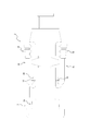
本実施形態に係るキャップ付きコネクタの使用方法は、図15に示すように、接続ステップS1と、プライミングステップS2と、取外しステップS3と、を有している。
本実施形態では、まず、接続ステップS1が行われる。接続ステップS1は、図10に示すような、キャップ3の接続口26aとコネクタ2の接続部5との非接続状態においてキャップ3がコネクタ2に取付けられた取付け状態を保持するように第1係合部28がコネクタ2(本実施形態では係合片15の係合部18)と係合した第1係合状態から、図12に示すような、キャップ3の接続口26aがコネクタ2の接続部5に接続された接続状態にするステップである。より具体的には、接続ステップS1においては、第1係合状態から、キャップ3の接続口26aがコネクタ2の接続部5に接続された接続状態においてキャップ3がコネクタ2に取付けられた取付け状態を保持するように第2係合部29がコネクタ2(本実施形態では係合片15の係合部18)と係合した第2係合状態にされる。
本実施形態では、接続ステップS1においては、第1係合状態から、キャップ3をコネクタ2に向けて捩らずに真っ直ぐ押し付ける操作により、第2係合状態にされる。一対の係合片15の係合部18は、それぞれ、包囲筒30の軸方向に沿って、近位端側から遠位端側に向けて第2係合部29に押し付けられることで、係合部18が径方向外側に移動するように一対の係合片15を揺動させて、第2係合部29を乗り越えることができる。一対の係合片15の係合部18の遠位端面には、このような乗り越えを生じるための傾斜面が設けられている。このような乗り越えを生じるために、一対の係合片15の係合部18の遠位端面に替えて、又は加えて、第2係合部29の近位端面に傾斜面を設けてもよい。本実施形態では、第1係合状態から、キャップ3のフランジ壁32が外周壁本体16aの遠位端面に当接するまでキャップ3を押し込むことにより、一対の係合片15の係合部18を第2係合部29に係合させて、第2係合状態にすることができる。
本実施形態では、接続ステップS1に次いで、プライミングステップS2が行われる。プライミングステップS2においては、図12に示されるように、液体流路4のプライミングが終了するまで、キャップ3の接続口26aがコネクタ2の接続部5に接続された接続状態(本実施形態では第2係合状態)が保持される。このとき、接続口26aから内腔26bに流入した気体は、フィルタ25を透過して排出口26cから外部へ排出される。液体流路4からの気体の排出が進み、液体が接続口26aに到達して内腔26bに流入すると、この液体は、フィルタ25を透過できずにフィルタ25によって堰き止められる。このようにして液体流路4のプライミングが終了する。
本実施形態では、プライミングステップS2に次いで、取外しステップS3が行われる。取外しステップS3においては、キャップ3の接続口26aがコネクタ2の接続部5に接続された接続状態から、図13に示すように、キャップ3がコネクタ2から取外される。より具体的には、取外しステップS3においては、第2係合状態から、第2係合部29とコネクタ2(本実施形態では係合片15の係合部18)との係合が解除されて、キャップ3がコネクタ2から取外される。このとき、係合片15の操作部19を径方向内側に押圧する操作により、係合片15の係合部18を径方向外側に移動させて、係合部18と第2係合部29との係合を容易に解除することができる。
本実施形態に係るキャップ付きコネクタの使用方法によれば、接続ステップS1を第1係合状態から行うようにしているので、液体流路4のプライミングを行う際にキャップ3を新たにコネクタ2に取付ける手間を省けるため、簡易な操作でプライミングを行うことができる。
前述した本実施形態は、本発明の実施形態の一例にすぎず、発明の要旨を逸脱しない範囲で種々変更可能であることはいうまでもない。
1 キャップ付きコネクタ
2 コネクタ
3 キャップ
4 液体流路
5 接続部
6 輸液ライン
7 輸液バッグ
8 輸液バッグ用コネクタ
9 チューブ
10 クレンメ
11 基部
11a チューブ接続部
11b 基部本体
11c 接続筒
11d 縮径部
12 弁体
13 弁体頭部
13a 周壁
13b 天壁
13c フランジ
13d 貫通口
14 弾性部
15 係合片
16 外周壁
16a 外周壁本体
17 ヒンジ
17a 第1部分
17b 第2部分
18 係合部
19 操作部
20 補強用リブ
21 第1部材
22 第2部材
23 第3部材
24 ハウジング
25 フィルタ
26 流路
26a 接続口
26b 内腔
26c 排出口
27 挿入筒
28 第1係合部
29 第2係合部
30 包囲筒
31 ハウジング本体
31a 第1端壁
31b 第2端壁
31c 筒壁
31d 拡径部
31e 第1端リブ
31f 第2端リブ
32 フランジ壁
33 外壁
34 第1部材
35 第2部材
36 回転阻止部
37 他の回転阻止部
2 コネクタ
3 キャップ
4 液体流路
5 接続部
6 輸液ライン
7 輸液バッグ
8 輸液バッグ用コネクタ
9 チューブ
10 クレンメ
11 基部
11a チューブ接続部
11b 基部本体
11c 接続筒
11d 縮径部
12 弁体
13 弁体頭部
13a 周壁
13b 天壁
13c フランジ
13d 貫通口
14 弾性部
15 係合片
16 外周壁
16a 外周壁本体
17 ヒンジ
17a 第1部分
17b 第2部分
18 係合部
19 操作部
20 補強用リブ
21 第1部材
22 第2部材
23 第3部材
24 ハウジング
25 フィルタ
26 流路
26a 接続口
26b 内腔
26c 排出口
27 挿入筒
28 第1係合部
29 第2係合部
30 包囲筒
31 ハウジング本体
31a 第1端壁
31b 第2端壁
31c 筒壁
31d 拡径部
31e 第1端リブ
31f 第2端リブ
32 フランジ壁
33 外壁
34 第1部材
35 第2部材
36 回転阻止部
37 他の回転阻止部
Claims (12)
- 液体流路に設けられた接続部を備えるコネクタと、
前記液体流路のプライミングのためのキャップと、を有し、
前記キャップは、
前記接続部に接続可能な接続口から内腔を介して排出口まで連なる流路を形成するハウジングと、
前記流路に設けられるとともに気体を透過させ且つ液体を透過させないフィルタと、を有し、
前記ハウジングは、前記接続口と前記接続部との非接続状態において前記キャップが前記コネクタに取付けられた取付け状態を保持するように前記コネクタと係合可能な第1係合部を有する、
キャップ付きコネクタ。 - 前記ハウジングは、前記接続口と前記接続部との接続状態において前記取付け状態を保持するように前記コネクタと係合可能な第2係合部を有する、請求項1に記載のキャップ付きコネクタ。
- 前記コネクタは、前記接続部に揺動可能に連結する係合片を有し、
前記係合片は、前記接続状態において前記取付け状態を保持するように前記第2係合部と係合可能な係合部を有するとともに、前記接続部に対する揺動によって前記係合部と前記第2係合部との係合を解除可能である、請求項2に記載のキャップ付きコネクタ。 - 前記ハウジングは、前記非接続状態における前記取付け状態において前記接続部を包囲する包囲筒を有する、請求項1~3のいずれか一項に記載のキャップ付きコネクタ。
- 前記第1係合部は、前記包囲筒に設けられている、請求項4に記載のキャップ付きコネクタ。
- 前記ハウジングは、前記非接続状態における前記取付け状態において前記包囲筒の軸心を中心とする前記コネクタに対する前記ハウジングの回転を阻止するように前記コネクタと係合可能な回転阻止部を有する、請求項4又は5に記載のキャップ付きコネクタ。
- 前記接続部は、接続筒を有し、
前記ハウジングは、前記接続口を備えるとともに前記接続口を前記接続部に接続するために前記接続筒に挿入可能な挿入筒を有する、
請求項1~6のいずれか一項に記載のキャップ付き医療用コネクタ。 - 液体流路のプライミングのために、前記液体流路に設けられた接続部を備えるコネクタに取付けられるキャップであって、
前記接続部に接続可能な接続口から内腔を介して排出口まで連なる流路を形成するハウジングと、
前記流路に設けられるとともに気体を透過させ且つ液体を透過させないフィルタと、を有し、
前記ハウジングは、
前記接続口と前記接続部との非接続状態において前記キャップが前記コネクタに取付けられた取付け状態を保持するように前記コネクタと係合可能な第1係合部と、
前記接続口と前記接続部との接続状態において前記取付け状態を保持するように前記コネクタと係合可能な第2係合部と、を有する、
キャップ。 - 前記ハウジングは、前記非接続状態における前記取付け状態において前記接続部を包囲する包囲筒を有し、
前記第1係合部及び前記第2係合部は、前記包囲筒の軸方向に並べて配置されている、請求項8に記載のキャップ。 - 前記第1係合部及び前記第2係合部は、それぞれ、前記包囲筒の外周面に設けられている、請求項9に記載のキャップ。
- 前記ハウジングは、前記非接続状態における前記取付け状態において前記包囲筒の軸心を中心とする前記コネクタに対する前記ハウジングの回転を阻止するように前記コネクタと係合可能な回転阻止部を有する、請求項9又は10に記載のキャップ。
- 液体流路に設けられた接続部を備えるコネクタと、
前記液体流路のプライミングのためのキャップと、を有し、
前記キャップは、
前記接続部に接続可能な接続口から内腔を介して排出口まで連なる流路を形成するハウジングと、
前記流路に設けられるとともに気体を透過させ且つ液体を透過させないフィルタと、を有し、
前記ハウジングは、前記接続口と前記接続部との非接続状態において前記キャップが前記コネクタに取付けられた取付け状態を保持するように前記コネクタと係合可能な第1係合部を有する、
キャップ付きコネクタの使用方法であって、
前記非接続状態において前記取付け状態を保持するように前記第1係合部が前記コネクタと係合した第1係合状態から、前記接続口と前記接続部との接続状態にする接続ステップと、
前記液体流路のプライミングが終了するまで前記接続状態を保持するプライミングステップと、
前記接続状態から前記キャップを前記コネクタから取外す取外しステップと、を有する、
キャップ付きコネクタの使用方法。
Priority Applications (1)
| Application Number | Priority Date | Filing Date | Title |
|---|---|---|---|
| JP2020552570A JP7356444B2 (ja) | 2018-10-23 | 2019-08-29 | キャップ付きコネクタ、キャップ、及びキャップ付きコネクタの使用方法 |
Applications Claiming Priority (2)
| Application Number | Priority Date | Filing Date | Title |
|---|---|---|---|
| JP2018199508 | 2018-10-23 | ||
| JP2018-199508 | 2018-10-23 |
Publications (1)
| Publication Number | Publication Date |
|---|---|
| WO2020084901A1 true WO2020084901A1 (ja) | 2020-04-30 |
Family
ID=70330416
Family Applications (1)
| Application Number | Title | Priority Date | Filing Date |
|---|---|---|---|
| PCT/JP2019/033997 Ceased WO2020084901A1 (ja) | 2018-10-23 | 2019-08-29 | キャップ付きコネクタ、キャップ、及びキャップ付きコネクタの使用方法 |
Country Status (2)
| Country | Link |
|---|---|
| JP (1) | JP7356444B2 (ja) |
| WO (1) | WO2020084901A1 (ja) |
Citations (5)
| Publication number | Priority date | Publication date | Assignee | Title |
|---|---|---|---|---|
| JP2009101093A (ja) * | 2007-10-25 | 2009-05-14 | Terumo Corp | コネクタおよび輸液チューブセット |
| JP2015503990A (ja) * | 2012-01-20 | 2015-02-05 | ケアフュージョン 303 インコーポレイテッド | 無針弁システム用ピストン |
| JP2017504441A (ja) * | 2014-01-31 | 2017-02-09 | インドゥストリー・ボルラ・ソシエタ・ペル・アチオニIndustrie Borla S.p.A. | 医用ラインのためのバルブ内蔵コネクタ |
| JP2017200534A (ja) * | 2016-05-06 | 2017-11-09 | 株式会社ジェイ・エム・エス | プライミング用キャップ |
| JP2018527128A (ja) * | 2015-09-21 | 2018-09-20 | ケアフュージョン 303、インコーポレイテッド | プライミング装置 |
-
2019
- 2019-08-29 WO PCT/JP2019/033997 patent/WO2020084901A1/ja not_active Ceased
- 2019-08-29 JP JP2020552570A patent/JP7356444B2/ja active Active
Patent Citations (5)
| Publication number | Priority date | Publication date | Assignee | Title |
|---|---|---|---|---|
| JP2009101093A (ja) * | 2007-10-25 | 2009-05-14 | Terumo Corp | コネクタおよび輸液チューブセット |
| JP2015503990A (ja) * | 2012-01-20 | 2015-02-05 | ケアフュージョン 303 インコーポレイテッド | 無針弁システム用ピストン |
| JP2017504441A (ja) * | 2014-01-31 | 2017-02-09 | インドゥストリー・ボルラ・ソシエタ・ペル・アチオニIndustrie Borla S.p.A. | 医用ラインのためのバルブ内蔵コネクタ |
| JP2018527128A (ja) * | 2015-09-21 | 2018-09-20 | ケアフュージョン 303、インコーポレイテッド | プライミング装置 |
| JP2017200534A (ja) * | 2016-05-06 | 2017-11-09 | 株式会社ジェイ・エム・エス | プライミング用キャップ |
Also Published As
| Publication number | Publication date |
|---|---|
| JP7356444B2 (ja) | 2023-10-04 |
| JPWO2020084901A1 (ja) | 2021-09-09 |
Similar Documents
| Publication | Publication Date | Title |
|---|---|---|
| JP6163198B2 (ja) | キャップ | |
| JP5161457B2 (ja) | 雄ルアーコネクター | |
| JP5215632B2 (ja) | コネクタのプライミング方法 | |
| JP6396347B2 (ja) | 無針アクセスコネクタおよび製造方法 | |
| JP5265680B2 (ja) | コネクタおよび輸液チューブセット | |
| EP2842540A1 (en) | Medical connector | |
| KR20020072281A (ko) | 커넥터 | |
| CN107073254B (zh) | 医疗用连接器 | |
| JP6450502B2 (ja) | 注射器用のフィルタ注射針組立体 | |
| JPH07328118A (ja) | 針を使用しない液体注入部材 | |
| JP2018515264A (ja) | 注射器用フィルター構造体およびこれを具備した注射器 | |
| WO2014162339A1 (ja) | コネクタ | |
| JP2018527128A (ja) | プライミング装置 | |
| WO2015145998A1 (ja) | 医療用コネクタ | |
| JP2016526950A (ja) | 接続デバイス | |
| JP3203662U (ja) | コネクタ | |
| WO2001043814A1 (en) | Connector | |
| JP6709777B2 (ja) | オスコネクタ及び輸液セット | |
| KR101749534B1 (ko) | 연장 가능한 수액세트용 멀티웨이 조립체 | |
| JP6638066B2 (ja) | 注射器 | |
| JP2010181028A (ja) | 逆止弁 | |
| JP7356444B2 (ja) | キャップ付きコネクタ、キャップ、及びキャップ付きコネクタの使用方法 | |
| JP2019517319A (ja) | 薬液注射用機器の外キャップ | |
| JP5523527B2 (ja) | 雄ルアーコネクター | |
| WO2021261500A1 (ja) | 外針組立体 |
Legal Events
| Date | Code | Title | Description |
|---|---|---|---|
| 121 | Ep: the epo has been informed by wipo that ep was designated in this application |
Ref document number: 19875787 Country of ref document: EP Kind code of ref document: A1 |
|
| ENP | Entry into the national phase |
Ref document number: 2020552570 Country of ref document: JP Kind code of ref document: A |
|
| NENP | Non-entry into the national phase |
Ref country code: DE |
|
| 122 | Ep: pct application non-entry in european phase |
Ref document number: 19875787 Country of ref document: EP Kind code of ref document: A1 |