WO2020084730A1 - 圧迫筒着脱ユニット - Google Patents
圧迫筒着脱ユニット Download PDFInfo
- Publication number
- WO2020084730A1 WO2020084730A1 PCT/JP2018/039635 JP2018039635W WO2020084730A1 WO 2020084730 A1 WO2020084730 A1 WO 2020084730A1 JP 2018039635 W JP2018039635 W JP 2018039635W WO 2020084730 A1 WO2020084730 A1 WO 2020084730A1
- Authority
- WO
- WIPO (PCT)
- Prior art keywords
- attachment
- main body
- connecting pin
- attaching
- compression cylinder
- Prior art date
- Legal status (The legal status is an assumption and is not a legal conclusion. Google has not performed a legal analysis and makes no representation as to the accuracy of the status listed.)
- Ceased
Links
Images








Classifications
-
- A—HUMAN NECESSITIES
- A61—MEDICAL OR VETERINARY SCIENCE; HYGIENE
- A61B—DIAGNOSIS; SURGERY; IDENTIFICATION
- A61B6/00—Apparatus or devices for radiation diagnosis; Apparatus or devices for radiation diagnosis combined with radiation therapy equipment
- A61B6/44—Constructional features of apparatus for radiation diagnosis
- A61B6/4429—Constructional features of apparatus for radiation diagnosis related to the mounting of source units and detector units
- A61B6/4458—Constructional features of apparatus for radiation diagnosis related to the mounting of source units and detector units the source unit or the detector unit being attached to robotic arms
-
- A—HUMAN NECESSITIES
- A61—MEDICAL OR VETERINARY SCIENCE; HYGIENE
- A61B—DIAGNOSIS; SURGERY; IDENTIFICATION
- A61B6/00—Apparatus or devices for radiation diagnosis; Apparatus or devices for radiation diagnosis combined with radiation therapy equipment
- A61B6/44—Constructional features of apparatus for radiation diagnosis
- A61B6/4476—Constructional features of apparatus for radiation diagnosis related to motor-assisted motion of the source unit
- A61B6/4482—Constructional features of apparatus for radiation diagnosis related to motor-assisted motion of the source unit involving power assist circuits
-
- A—HUMAN NECESSITIES
- A61—MEDICAL OR VETERINARY SCIENCE; HYGIENE
- A61B—DIAGNOSIS; SURGERY; IDENTIFICATION
- A61B6/00—Apparatus or devices for radiation diagnosis; Apparatus or devices for radiation diagnosis combined with radiation therapy equipment
- A61B6/48—Diagnostic techniques
- A61B6/486—Diagnostic techniques involving generating temporal series of image data
- A61B6/487—Diagnostic techniques involving generating temporal series of image data involving fluoroscopy
Definitions
- the present invention relates to a compression cylinder attachment / detachment unit.
- Patent Document 1 JP-A-2000-166915
- the compression mechanism of the radiographic imaging apparatus described in Patent Document 1 includes a guide, a tubular metal member, a support rod, an operating grip, and a compression tube.
- the guide is provided in the X-ray image system.
- the tubular fitting slides up and down on the guide.
- the support rod is vertically attached to the tubular fitting.
- the operation grip is provided at the tip of the support rod.
- the compression cylinder is provided in the middle of the support rod.
- the compression tube When the compression tube is not used, the compression tube may be removed from the fluoroscopic imaging device.
- the work for attaching and detaching the compression tube is complicated.
- the present invention has been made in view of the above problems, and an object of the present invention is to provide a compression tube attaching / detaching unit capable of easily attaching / detaching the compression tube.
- the compression tube attachment / detachment unit includes an arm, a connecting pin, and an attachment / detachment mechanism section.
- the arm supports the compression cylinder.
- the attachment / detachment mechanism portion is detachably connected to the connection pin to attach the arm to the radiographic imaging apparatus.
- the connecting pin has a shaft portion and a flange portion located at the tip of the shaft portion.
- the attachment / detachment mechanism section includes a main body section, a lid section, a lock section, and an unlock section.
- the main body portion has a groove portion into which the flange portion is slidably inserted.
- the lid portion has a notch portion into which the shaft portion is slidably inserted, and is fixed to the main body portion so that the flange portion can be housed between the lid portion and the main body portion.
- the lock part is attached to the main body part so as to be positioned on the slide insertion path of the flange part, is provided so as to be able to come into contact with and separate from the lid part, and receives a biasing force in a direction approaching the lid part.
- the unlock part is attached to the main body part and separates the lock part from the lid part against the biasing force.
- An inclined surface that is in sliding contact with the slide-inserted flange portion is provided at the tip of the lid portion side of the lock portion. The inclined surface is inclined so as to be positioned in the slide insertion direction of the flange portion toward the tip of the lock portion.
- the connecting pin can be easily attached to and detached from the attachment / detachment mechanism, and the compression cylinder can be attached / detached easily.
- each of the shaft portion and the flange portion has a cylindrical outer shape.
- the connecting pin can be slid and connected in a direction relatively approaching the attachment / detachment mechanism portion to be connected.
- the arm can rotate about the connecting pin as the rotation axis via the attachment / detachment mechanism section.
- the compression tube can be easily moved between the inside and outside of the X-ray field of view of the image system.
- an operation grip for manually rotating the compression cylinder is provided at the end of the arm opposite to the attachment / detachment mechanism side.
- the attachment / detachment mechanism section further includes an elastic body.
- the elastic body is attached to the main body so as to be located in the groove, and urges the flange portion housed between the main body and the lid toward the lid.
- the connecting pin can be stably connected to the attachment / detachment mechanism. As a result, it is possible to stably support the compression cylinder.
- the compression cylinder can be easily attached and detached.
- FIG. 5 is a side view of the housing and the connecting pin of FIG. 4 viewed from the arrow V direction.
- FIG. 9 is a rear view of the attachment / detachment mechanism portion of FIG. 8 viewed from the direction of arrow XI.
- FIG. 10 is a cross-sectional view of the attachment / detachment mechanism portion of FIG. 9 viewed from a direction of an arrow XII-XII.
- FIG. 10 is a cross-sectional view of the attachment / detachment mechanism portion of FIG. 9 viewed from a direction of an arrow XIII-XIII.
- FIG. 6 is a side view showing a state in which the connecting pin is brought close to the attachment / detachment mechanism portion in the compression tube attachment / detachment unit according to the embodiment of the present invention.
- FIG. 10 is a cross-sectional view of the attachment / detachment mechanism portion of FIG. 9 viewed from a direction of an arrow XII-XII.
- FIG. 10 is a cross-sectional view of the attachment / detachment mechanism portion of FIG. 9 viewed from a direction of an arrow XIII-XIII.
- FIG. 6 is a side view showing a state in which the connecting
- FIG. 6 is a side view showing a state in which the flange portion of the connecting pin is in contact with the inclined surface of the lock portion and pushes down the lock portion in the compression tube attaching / detaching unit according to the embodiment of the present invention.
- FIG. 6 is a side view showing a state in which the connecting pin is connected to the attaching / detaching mechanism portion in the compression tube attaching / detaching unit according to the embodiment of the present invention.
- FIG. 6 is a side view showing a state in which the unlocking portion is rotated downward to remove the connecting pin from the attaching / detaching mechanism portion in the compression tube attaching / detaching unit according to the embodiment of the present invention.
- FIG. 6 is a side view showing a state in which the connecting pin is removed from the attaching / detaching mechanism portion in the compression tube attaching / detaching unit according to the embodiment of the present invention.
- FIG. 6 is a perspective view illustrating the slide insertion direction of the connecting pin with respect to the attachment / detachment mechanism portion in the compression tube attachment / detachment unit according to the embodiment of the present invention.
- FIG. 1 is a side view showing a configuration of a radiographic imaging apparatus including a compression tube attachment / detachment unit according to an embodiment of the present invention.
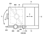
- FIG. 2 is a plan view of the radiographic imaging apparatus of FIG. 1 viewed from the direction of arrow II. 1 and 2, the state in which the crimping cylinder is located outside the X-ray field is shown by a solid line.
- a radiographic imaging apparatus 10 including a compression tube attachment / detachment unit includes a bed 11, a column 12, a frame 13, an image system 14, and an operation. It includes a handle 15 and a compression cylinder attaching / detaching unit.
- the radiographic imaging apparatus 10 irradiates the imaging target S on the bed 11 with radiation to perform fluoroscopic imaging.
- An X-ray tube is arranged inside the bed 11.
- the pillar 12 extends upward from the side of the bed 11.
- the frame 13 is attached to the column 12 so as to be movable in the vertical direction indicated by the arrow 1.
- the image system 14 has an X-ray field of view as indicated by the chain double-dashed line in FIG.
- the operation handle 15 is attached to the side of the video system 14 opposite to the side of the column 12.
- the image system 14 is attached to the frame 13 so as to be movable in the left-right direction indicated by the arrow 2.
- the video system 14 has a function of detecting a force applied to the operation handle 15 and power assisting the vertical movement and the front-back movement of the video system 14 by a motor.
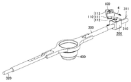
- FIG. 3 is a perspective view showing the configuration of the compression tube attachment / detachment unit according to the embodiment of the present invention.
- the compression cylinder attachment / detachment unit includes an arm 300, a connecting pin 110, and an attachment / detachment mechanism section 200.
- the arm 300 supports the compression cylinder 400.
- the attachment / detachment mechanism portion 200 attaches the arm 300 to the radiographic imaging apparatus 10 by being detachably connected to the connection pin 110.
- the connecting pin 110 is fixed to the housing 100.
- the housing 100 is connected to the lower part on the front side of the video system 14.
- the attachment / detachment mechanism section 200 is attached to the video system 14 via the connecting pin 110 and the housing 100.
- the arm 300 can be horizontally rotated through the attachment / detachment mechanism section 200 with the connecting pin 110 as a rotation axis as indicated by an arrow 3.
- the compression cylinder 400 moves between the inside and outside of the X-ray field of the image system 14.
- connection part 310 connected to the attachment / detachment mechanism part 200 is provided at the end of the arm 300.
- the connection portion 310 is provided with an engagement groove 311 into which a set screw attached to the main body of the attachment / detachment mechanism portion 200 described later is inserted.
- An operation grip 320 for manually rotating the compression cylinder 400 is provided at the end of the arm 300 opposite to the attachment / detachment mechanism 200 side.
- the operation grip 320 is provided with a lock switch (not shown).
- a compression cylinder 400 is attached to the middle part of the arm 300.
- a lock provided on the operation grip 320 in a state where the operation grip 320 is held and the compression tube 400 is manually pressed against the imaging target S.
- the switch By pressing the switch, the compression of the object S by the compression cylinder 400 is maintained.
- the lock switch again after completion of the fluoroscopic imaging, the compression of the imaging target S by the compression tube 400 is released.
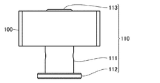
- FIG. 4 is a plan view showing a state in which the connecting pin included in the compression tube attaching / detaching unit according to the embodiment of the present invention is fixed to the housing.
- FIG. 5 is a side view of the housing and the connecting pin of FIG. 4 viewed from the arrow V direction.
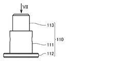
- FIG. 6 is a side view showing the structure of the connecting pin included in the compression tube attaching / detaching unit according to the embodiment of the present invention.
- FIG. 7 is a plan view of the connecting pin of FIG. 6 viewed from the arrow VII direction.
- the connecting pin 110 has a shaft portion 111 and a flange portion 112 located at the tip of the shaft portion 111.
- each of the shaft portion 111 and the flange portion 112 has a cylindrical outer shape.
- the shape of each of the shaft portion 111 and the flange portion 112 is not limited to a columnar shape, and may be a prismatic shape.
- the shaft portion 111 and the flange portion 112 are located coaxially.
- the connecting pin 110 further has a reduced diameter portion 113 having a diameter smaller than that of the shaft portion 111 on the side opposite to the flange portion 112 side of the shaft portion 111.
- the reduced diameter portion 113 has a cylindrical outer shape.
- the shape of the reduced diameter portion 113 is not limited to the cylindrical shape, and may be a prismatic shape.
- the shaft portion 111 and the reduced diameter portion 113 are positioned coaxially.
- the housing 100 has a through hole into which the reduced diameter portion 113 of the connecting pin 110 is inserted.
- the connecting pin 110 is fixed to the housing 100 in a state where the reduced diameter portion 113 is inserted into the through hole of the housing 100.
- each of the shaft portion 111 and the flange portion 112 is located below the housing 100.
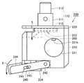
- FIG. 8 is a perspective view showing the external appearance of the attachment / detachment mechanism portion included in the compression tube attachment / detachment unit according to the embodiment of the present invention.
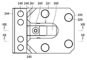
- FIG. 9 is a plan view of the attachment / detachment mechanism portion of FIG. 8 viewed from the direction of arrow IX.
- FIG. 10 is a side view of the attachment / detachment mechanism portion of FIG. 8 viewed from the direction of arrow X.
- FIG. 11 is a rear view of the attachment / detachment mechanism portion of FIG. 8 seen from the arrow XI direction.
- FIG. 12 is a cross-sectional view of the attachment / detachment mechanism portion of FIG. 9 seen from the direction of the arrow XII-XII.
- FIG. 13 is a cross-sectional view of the attachment / detachment mechanism portion of FIG. 9 seen from the direction of the arrow XIII-XIII.
- the attachment / detachment mechanism section 200 includes a main body section 210, a lid section 220, a pair of lock pins 230 as a lock section, and a pair of unlock levers 240 as an unlock section.
- the attachment / detachment mechanism section 200 further includes an elastic body 260.
- the main body 210 has a substantially rectangular parallelepiped outer shape.
- the main body 210 is provided with a through hole 211 into which the connecting portion 310 of the arm 300 is inserted.
- the through hole 211 extends from the right side surface to the left side surface of the main body 210.
- a set screw 211k for fixing the connecting portion 310 of the arm 300 inserted into the through hole 211 is attached to the main body 210. That is, the body 210 is provided with a female screw that is screwed with the set screw 211k. The tip of the set screw 211k projects inside the through hole 211. The tip of the set screw 211k engages with the bottom surface of the engagement groove 311 of the connecting portion 310 of the arm 300 shown in FIG. 3, whereby the arm 300 is fixed to the main body 210.
- a groove portion 212 into which the flange portion 112 of the connecting pin 110 is relatively slid and inserted is provided on the upper surface of the main body portion 210.
- the groove portion 212 has a U-shape in which the front side of the main body 210 is open when viewed from a direction orthogonal to the upper surface of the main body 210.
- the width of the groove portion 212 is slightly larger than the diameter of the flange portion 112.
- a deep groove portion 213 having a bottom surface below the bottom surface of the groove portion 212 is provided in the upper portion on the front side of the main body portion 210.
- the deep groove portion 213 has a U-shape in which the front side of the main body 210 is open when viewed from the direction orthogonal to the upper surface of the main body 210.
- a female screw extending downward is provided on the bottom surface of the deep groove portion 213.
- the main body 210 is provided with two stepped holes 214 into which a pair of lock pins 230 are inserted correspondingly.
- a recess 215 extending in the left-right direction is provided on the lower surface on the front side of the main body 210 so as to be continuous with the lower ends of the two stepped holes 214.
- a U-shaped vertical groove portion 216 having an open lower surface is provided at the center in the left-right direction.
- Two female screws extending in the front-rear direction are provided on the bottom surface of the vertical groove portion 216.
- the body 210 is made of resin such as epoxy resin or metal such as stainless steel.
- the lid 220 is formed of a flat plate having a rectangular outer shape that is substantially the same as the upper surface of the main body 210.
- the lid portion 220 is provided with a cutout portion 221 into which the shaft portion 111 of the connecting pin 110 is relatively slid and inserted.
- the cutout portion 221 has a U-shaped shape in which the front side of the lid portion 220 is open when viewed from a direction orthogonal to the upper surface of the lid portion 220.
- the central axis extending in the front-rear direction of the cutout portion 221 of the lid 220 substantially overlaps the central axis extending in the front-rear direction of the groove 212 of the main body 210.
- the width of the cutout portion 221 is slightly larger than the diameter of the shaft portion 111. At the front end of the cutout portion 221, the width of the cutout portion 221 is widened in order to guide the shaft portion 111 to the inside of the cutout portion 221.
- the lid 220 is made of metal such as stainless steel.
- the lid 220 is fixed on the upper surface of the main body 210 by four screws 229.
- the lid portion 220 and the groove portion 212 of the main body portion 210 form a space capable of accommodating the flange portion 112 of the connecting pin 110.
- each of the pair of lock pins 230 that is the lock portion is a stepped pin having a large diameter portion and a small diameter portion.
- An inclined surface 231 is provided at the end of the large diameter portion.
- a female screw located on the central axis of the small diameter portion is provided at the end of the small diameter portion opposite to the large diameter portion.
- the lock pin 230 is inserted into the corresponding stepped hole 214 of the main body 210 from the small diameter side.
- the lock pin 230 is made of metal such as stainless steel.
- a compression coil spring which is a biasing member 233, is arranged so as to be sandwiched between the step of the stepped hole 214 and the step of the lock pin 230.
- the lock pin 230 receives an upward biasing force from the biasing member 233.
- Each of the pair of lock pins 230 is connected to the connecting block 234 arranged in the recess 215 of the main body 210 by the head screw 239.
- the connecting block 234 is provided with two counter boring holes penetrating in the vertical direction at positions corresponding to the female threads of the small diameter portions of the pair of lock pins 230.
- the head screw 239 inserted into the counterbore hole of the connecting block 234 is screwed into the female screw of the small diameter portion of the lock pin 230, so that the pair of lock pins 230 and the connecting block 234 are connected to each other. .
- each of the pair of lock pins 230 which is the lock portion, is attached to the main body portion 210 so as to be positioned on the slide insertion path of the flange portion 112 of the connecting pin 110. It is provided so as to be able to come into contact with and separate from the lid portion 220, and receives a biasing force in a direction approaching the lid portion 220.
- an inclined surface that is in sliding contact with the flange portion 112 of the connecting pin 110 that is slidably inserted into the tip of each of the pair of lock pins 230, which is the lock portion, on the side of the lid portion 220. 231 is provided.
- the inclined surface 231 is inclined so as to be located in the slide insertion direction of the flange 112 as it approaches the tip of the lock pin 230.
- the slide insertion direction of the flange 112 is the direction indicated by the arrow 4 in FIG. 3, and is substantially parallel to the central axes of the groove 212 of the main body 210 and the cutout 221 of the lid 220.
- the inclined surfaces 231 of the pair of lock pins 230 are opposed to each other in an inclined state. Specifically, when viewed from the axial direction of the lock pin 230, the ridge line of the edge of the inclined surface 231 located at the upper end of the lock pin 230 is inclined so as to be located on the front side as the distance from the central axis of the cutout portion 221 increases. ing.
- each of the inclined surfaces 231 of the pair of lock pins 230 is provided as described above, the center of the flange portion 112 of the connecting pin 110 in contact with each of the inclined surfaces 231 of the pair of lock pins 230.
- the relative positional relationship between the connecting pin 110 and the attachment / detachment mechanism part 200 can be adjusted so that the position is located on the central axis of the groove part 212 of the main body part 210.
- each of the pair of unlock levers 240 which is an unlock part, rotates about a rotary shaft 242 fixed to a side part of the main body part 210. It is movably attached to the main body 210.
- the unlock lever 240 is made of metal such as stainless steel.
- Each of the pair of unlock levers 240 extends in the front-rear direction.
- a grip portion 244 is fixed by four screws 249 to a portion of the pair of unlock levers 240 located in front of the main body portion 210.
- the grip portion 244 has an L-shaped outer shape in a cross section. As shown in FIG. 13, the engaged surface 244b is exposed at the left-right center of the upper surface inside the grip 244.
- a long hole 241 extending in the front-rear direction is provided on each side surface of the pair of unlock levers 240.
- Corresponding connecting shafts 243 fixed to the opposite side surfaces of the connecting block 234 are inserted into the long holes 241 of the pair of unlock levers 240, respectively.
- the connecting shaft 243 extends in the left-right direction.
- the unlocking lever 240 is rotated about the rotating shaft 242 while the connecting shaft 243 is moved in the longitudinal direction within the elongated hole 241.
- a stopper 250 is attached to the vertical groove 216 of the main body 210.
- the stopper 250 has a mounting portion 251 extending in the vertical direction and a bent portion 252 bent forward from the lower end of the mounting portion 251.
- the attachment portion 251 of the stopper 250 is fixed in the vertical groove portion 216 by two screws 259 screwed into a female screw provided on the bottom surface of the vertical groove portion 216.
- the upper surface of the bent portion 252 of the stopper 250 is an engagement surface that engages with the engaged surface 244b of the grip portion 244 when the unlock lever 240 rotates downward.
- the engagement of the engaged surface 244b and the engaging surface restricts the rotation of the unlock lever 240.
- the unlocking part separates the locking part from the lid part 220 against the biasing force of the biasing member 233. Specifically, by pushing down the grip portion 244, the pair of unlock levers 240 both rotate downward, and the connecting shaft 243 moves down inside the elongated hole 243 while moving to the rotating shaft 242 side. As a result, the pair of lock pins 230 both move down against the biasing force of the biasing member 233.
- the distance between the rotary shaft 242 and the grip portion 244 is longer than the distance between the rotary shaft 242 and the connecting shaft 243, and therefore the lever portion can push down the grip portion 244 with a small force.
- the leaf spring which is the elastic body 260, is attached to the main body 210 so as to be located in the groove 212.
- the elastic body 260 is not limited to a leaf spring and may be rubber or the like. Further, the elastic body 260 does not necessarily have to be provided.
- the leaf spring which is the elastic body 260, includes a mounting portion that contacts the bottom surface of the deep groove portion 213 of the main body portion 210, an inclined portion that extends obliquely upward from the edge of the mounting portion, and a groove portion from the tip of the inclined portion. And a pressing portion extending along the bottom surface of 212.
- the leaf spring which is the elastic body 260, is attached to the main body portion 210 by sandwiching the attachment portion between the fixed block 261 and the deep groove portion 213 arranged in the deep groove portion 213 of the main body portion 210.
- each of the fixing block 261 and the elastic body 260 is provided with a through hole penetrating in the vertical direction, and a screw 269 inserted through these through holes is formed with a female screw provided on the bottom surface of the deep groove portion 213.
- the leaf spring is attached to the main body 210.
- the inclined portion of the leaf spring is separated from the bottom surface of the groove 212 and is located on the slide insertion path of the flange 112 of the connecting pin 110.
- the elastic body 260 biases the flange portion 112 of the connecting pin 110 housed between the main body portion 210 and the lid portion 220 toward the lid portion 220.
- FIG. 14 is a side view showing a state in which the connecting pin is brought close to the attachment / detachment mechanism portion in the compression tube attachment / detachment unit according to the embodiment of the present invention.
- the connection pin 110 moves in a direction relatively approaching the attachment / detachment mechanism section 200 as indicated by an arrow 4. Slide to move.
- FIG. 15 is a side view showing a state in which the flange portion of the connecting pin pushes the inclined surface of the lock portion and pushes down the lock portion in the compression tube attaching / detaching unit according to the embodiment of the present invention.
- the flange portion 112 of the connecting pin 110 presses the inclined surface 231 of the lock pin 230, so that the lock pin 230 is pushed down against the urging force of the urging member 233 as indicated by arrow 5. .
- the unlock lever 240 rotates downward as indicated by the arrow 6.
- FIG. 16 is a side view showing a state in which the connecting pin is connected to the attaching / detaching mechanism portion in the compression cylinder attaching / detaching unit according to the embodiment of the present invention.
- the connecting pin 110 when the connecting pin 110 is connected to the attaching / detaching mechanism part 200, the flange part 112 of the connecting pin 110 is housed between the main body part 210 and the lid part 220, and the lock pin As indicated by arrow 7, 230 is moved up by the urging force of the urging member 233 and is in contact with the lid 220.
- the unlock lever 240 rotates upward as indicated by the arrow 8.
- the inclined surface 231 is not located on the flange portion 112 side of the lock pin 230. Therefore, even when the lock pin 230 and the flange 112 are in contact with each other, the force of pushing down the lock pin 230 does not work. Therefore, the connecting pin 110 is maintained in a state of being connected to the attaching / detaching mechanism part 200 by the lock pin 230 which is a lock part.
- FIG. 17 is a side view showing a state in which the unlock portion is rotated downward to remove the connecting pin from the attaching / detaching mechanism portion in the compression tube attaching / detaching unit according to the embodiment of the present invention.
- FIG. 18 is a side view showing a state in which the connecting pin is removed from the attaching / detaching mechanism portion in the compression tube attaching / detaching unit according to the embodiment of the present invention.
- the connecting pin 110 is slid in a direction relatively away from the attaching / detaching mechanism portion 200 as indicated by an arrow 9, and The connection with the attachment / detachment mechanism section 200 is released.
- FIG. 19 is a perspective view illustrating the slide insertion direction of the connecting pin with respect to the attaching / detaching mechanism portion in the compression tube attaching / detaching unit according to the embodiment of the present invention.
- each of the shaft portion 111 and the flange portion 112 of the connecting pin 110 has a cylindrical outer shape, and thus 360 °. In either direction, the connecting pin 110 can be slid in a direction relatively closer to the attachment / detachment mechanism section 200 to be connected.
- the attachment / detachment mechanism section 200 includes the main body section 210, the lid section 220, the lock section, and the unlock section, whereby the attachment / detachment mechanism section is attached.
- 200 can be connected by sliding in a direction relatively close to 200, and the connecting pin 110 can be slid in a direction relatively away from the attaching / detaching mechanism part 200 in a state where the unlock part is rotated. By doing so, the connection can be released. Therefore, the connecting pin 110 can be easily attached to and detached from the attachment / detachment mechanism section 200. As a result, the compression cylinder 400 can be easily attached and detached.
- the arm 300 can rotate about the connecting pin 110 as a rotation axis via the attachment / detachment mechanism section 200.
- the compression cylinder 400 can be easily moved between the inside and outside of the X-ray field of the image system 14.
- an operation grip 320 for manually rotating the compression cylinder 400 is provided at the end of the arm 300 opposite to the attachment / detachment mechanism 200 side. This makes it possible to finely adjust the force with which the compression cylinder 400 is pressed against the object S to be photographed, as compared with the case where the power assist of the motor is used. As a result, it is possible to prevent the pressing force of the compression cylinder 400 from becoming excessive.
- the attachment / detachment mechanism part 200 is attached to the main body part 210 so as to be positioned in the groove part 212, and the flange part 112 housed between the main body part 210 and the cover part 220 is attached to the cover part 220 side.
- a biasing elastic body 260 is further included. Accordingly, the connecting pin 110 can be stably connected to the attachment / detachment mechanism section 200. As a result, the compression cylinder 400 can be stably supported.
- radiographic imaging apparatus 11 bed, 12 support section, 13 frame, 14 image system, 15 operation handle, 100 housing, 110 connecting pin, 111 shaft section, 112 flange section, 113 reduced diameter section, 200 attaching / detaching mechanism section, 210 Body part, 211 through hole, 211k set screw, 212, 213 groove part, 214 stepped hole, 215 recessed part, 216 vertical groove part, 220 lid part, 221 notch part, 229, 249, 259, 269 screw, 230 lock pin, 231 Inclined surface, 233 biasing member, 234 connecting block, 239 head screw, 240 unlock lever, 241, long hole, 242 rotating shaft, 243 connecting shaft, 244 gripping part, 244b engaged surface, 250 stopper, 251 mounting Section, 252 bent section, 260 elasticity , 311 engagement groove 320 operating grip, 400 compression unit, 2000 JP, S shooting target.
Landscapes
- Health & Medical Sciences (AREA)
- Engineering & Computer Science (AREA)
- Life Sciences & Earth Sciences (AREA)
- Medical Informatics (AREA)
- Optics & Photonics (AREA)
- Biomedical Technology (AREA)
- Biophysics (AREA)
- High Energy & Nuclear Physics (AREA)
- Robotics (AREA)
- Nuclear Medicine, Radiotherapy & Molecular Imaging (AREA)
- Automation & Control Theory (AREA)
- Pathology (AREA)
- Radiology & Medical Imaging (AREA)
- Physics & Mathematics (AREA)
- Heart & Thoracic Surgery (AREA)
- Molecular Biology (AREA)
- Surgery (AREA)
- Animal Behavior & Ethology (AREA)
- General Health & Medical Sciences (AREA)
- Public Health (AREA)
- Veterinary Medicine (AREA)
- Apparatus For Radiation Diagnosis (AREA)
Abstract
圧迫筒着脱ユニットは、アーム(300)と連結ピン(110)と着脱機構部(200)とを備える。アーム(300)は、圧迫筒(400)を支持する。着脱機構部(200)は、連結ピン(110)と着脱可能に連結されることにより、アーム(300)を放射線透視撮影装置に対して装着する。連結ピン(110)は、軸部(111)、および、軸部(111)の先端に位置するフランジ部(112)を有する。着脱機構部(200)は、本体部と蓋部とロック部とアンロック部とを含む。
Description
本発明は、圧迫筒着脱ユニットに関する。
圧迫機構を有する放射線透視撮影装置の構成を開示した先行文献として、特開2000-166915号公報(特許文献1)がある。特許文献1に記載された放射線透視撮影装置の圧迫機構は、ガイドと、筒状金具と、支持棒と、操作グリップと、圧迫筒とを含む。ガイドは、X線映像系に設けられている。筒状金具は、ガイド上を上下にスライドする。支持棒は、筒状金具に垂直に取り付けられている。操作グリップは、支持棒の先端に設けられている。圧迫筒は、支持棒の中間に設けられている。
圧迫筒を使用しないときに、圧迫筒を透視撮影装置から取り外す場合がある。従来の透視撮影装置においては、圧迫筒を着脱する際の作業が複雑であった。
本発明は上記の問題点に鑑みてなされたものであって、簡易に圧迫筒を着脱することができる、圧迫筒着脱ユニットを提供することを目的とする。
本発明に基づく圧迫筒着脱ユニットは、アームと連結ピンと着脱機構部とを備える。アームは、圧迫筒を支持する。着脱機構部は、連結ピンと着脱可能に連結されることにより、アームを放射線透視撮影装置に対して装着する。連結ピンは、軸部、および、軸部の先端に位置するフランジ部を有する。着脱機構部は、本体部と蓋部とロック部とアンロック部とを含む。本体部は、フランジ部が相対的にスライド挿入される溝部を有する。蓋部は、軸部が相対的にスライド挿入される切欠部を有し、本体部との間でフランジ部を収容可能に本体部に固定されている。ロック部は、フランジ部のスライド挿入経路上に位置するように本体部に取り付けられており、蓋部に対して接離可能に設けられるとともに蓋部に近づく方向に付勢力を受ける。アンロック部は、本体部に取り付けられており、ロック部を上記付勢力に抗して蓋部から離間させる。ロック部の蓋部側の先端には、スライド挿入されるフランジ部と摺接する傾斜面が設けられている。上記傾斜面は、ロック部の先端に向かうにしたがってフランジ部のスライド挿入方向に位置するように傾斜している。
これにより、連結ピンを着脱機構部に容易に着脱させることができ、圧迫筒を簡易に着脱することができる。
本発明の一形態においては、軸部およびフランジ部の各々は、円柱状の外形を有している。
これにより、360°いずれの方向においても、着脱機構部に対して連結ピンを相対的に近づく方向にスライド移動させて連結させることができる。
本発明の一形態においては、アームは、着脱機構部を介して連結ピンを回動軸として回動可能である。
これにより、圧迫筒を映像系のX線視野内とX線視野外との間で容易に移動させることができる。
本発明の一形態においては、アームの着脱機構部側とは反対側の端部に、圧迫筒を手動で回動させるための操作グリップが設けられている。
これにより、撮影対象に圧迫筒を押し付ける力を、モータのパワーアシストを用いた場合に比較して微調整することができる。その結果、圧迫筒の押し付け力が過度になることを抑制できる。
本発明の一形態においては、着脱機構部は、弾性体をさらに含む。弾性体は、溝部内に位置するように本体部に取り付けられており、本体部と蓋部との間に収容されているフランジ部を蓋部側に付勢する。
これにより、連結ピンを着脱機構部と安定して連結させることができる。その結果、圧迫筒を安定して支持することが可能となる。
本発明によれば、簡易に圧迫筒を着脱することができる。
以下、本発明の一実施形態に係る圧迫筒着脱ユニットを含む放射線透視撮影装置について説明する。以下の実施形態の説明においては、図中の同一または相当部分には同一符号を付して、その説明は繰り返さない。
図1は、本発明の一実施形態に係る圧迫筒着脱ユニットを含む放射線透視撮影装置の構成を示す側面図である。図2は、図1の放射線透視撮影装置を矢印II方向から見た平面図である。図1および図2においては、圧着筒がX線視野の外側に位置している状態を実線で図示している。
図1および図2に示すように、本発明の一実施形態に係る圧迫筒着脱ユニットを含む放射線透視撮影装置10は、寝台11と、支柱部12と、フレーム13と、映像系14と、操作ハンドル15と、圧迫筒着脱ユニットとを含む。
放射線透視撮影装置10は、寝台11上に乗った撮影対象Sに放射線を照射して透視撮影する。寝台11の内部に、X線管が配置されている。支柱部12は、寝台11の側部から上方に向けて延在している。フレーム13は、支柱部12に対して矢印1で示す上下方向に移動可能に取り付けられている。映像系14は、図2の2点鎖線で示すようなX線視野を有している。
映像系14の支柱部12側とは反対側の側部に、操作ハンドル15が取り付けられている。映像系14は、フレーム13に対して矢印2で示す左右方向に移動可能に取り付けられている。映像系14には、操作ハンドル15に加えられる力を検出して、映像系14の上下動および前後動の各々をモータによってパワーアシストする機能が備えられている。
映像系14の前方側の下部に、圧迫筒着脱ユニットが設けられている。図3は、本発明の一実施形態に係る圧迫筒着脱ユニットの構成を示す斜視図である。図1~図3に示すように、圧迫筒着脱ユニットは、アーム300と連結ピン110と着脱機構部200とを備える。
アーム300は、圧迫筒400を支持する。着脱機構部200は、連結ピン110と着脱可能に連結されることにより、アーム300を放射線透視撮影装置10に対して装着する。具体的には、連結ピン110は、ハウジング100に固定されている。ハウジング100は、映像系14の前方側の下部に接続されている。着脱機構部200は、連結ピン110およびハウジング100を介して映像系14に取り付けられる。
アーム300は、着脱機構部200を介して連結ピン110を回動軸として矢印3で示すように水平方向に回動可能である。アーム300が回動することにより、圧迫筒400が映像系14のX線視野内とX線視野外との間を移動する。
アーム300の端部に、着脱機構部200と接続される接続部310が設けられている。接続部310には、後述する着脱機構部200の本体部に取り付けられる止めねじが差し込まれる係合溝311が設けられている。
アーム300の着脱機構部200側とは反対側の端部に、圧迫筒400を手動で回動させるための操作グリップ320が設けられている。操作グリップ320には、図示しないロックスイッチが設けられている。
アーム300の中間部に、圧迫筒400が取り付けられている。圧迫筒400によって撮影対象Sを圧迫しつつ透視撮影する際には、操作グリップ320を把持して圧迫筒400を撮影対象Sに手動で押し当てた状態で、操作グリップ320に設けられているロックスイッチを押すことにより、圧迫筒400による撮影対象Sの圧迫を維持する。透視撮影終了後にロックスイッチを再度押すことにより、圧迫筒400による撮影対象Sの圧迫が解除される。
以下、本発明の一実施形態に係る圧迫筒着脱ユニットの構成について詳細に説明する。
図4は、本発明の一実施形態に係る圧迫筒着脱ユニットに含まれる連結ピンがハウジングに固定されている状態を示す平面図である。図5は、図4のハウジングおよび連結ピンを矢印V方向から見た側面図である。図6は、本発明の一実施形態に係る圧迫筒着脱ユニットに含まれる連結ピンの構造を示す側面図である。図7は、図6の連結ピンを矢印VII方向から見た平面図である。
図4は、本発明の一実施形態に係る圧迫筒着脱ユニットに含まれる連結ピンがハウジングに固定されている状態を示す平面図である。図5は、図4のハウジングおよび連結ピンを矢印V方向から見た側面図である。図6は、本発明の一実施形態に係る圧迫筒着脱ユニットに含まれる連結ピンの構造を示す側面図である。図7は、図6の連結ピンを矢印VII方向から見た平面図である。
図4~図7に示すように、連結ピン110は、軸部111、および、軸部111の先端に位置するフランジ部112を有する。本実施形態においては、軸部111およびフランジ部112の各々は、円柱状の外形を有している。ただし、軸部111およびフランジ部112の各々の形状は、円柱状に限られず、角柱状でもよい。軸部111とフランジ部112とは、同軸状に位置している。
連結ピン110は、軸部111のフランジ部112側とは反対側に、軸部111より径の小さい縮径部113をさらに有する。本実施形態においては、縮径部113は、円柱状の外形を有している。ただし、縮径部113の形状は、円柱状に限られず、角柱状でもよい。軸部111と縮径部113とは、同軸状に位置している。
ハウジング100は、連結ピン110の縮径部113が挿通される貫通孔を有している。ハウジング100の貫通孔に縮径部113が挿通された状態で、連結ピン110がハウジング100に固定されている。連結ピン110がハウジング100に固定された状態において、軸部111およびフランジ部112の各々は、ハウジング100の下方に位置している。
図8は、本発明の一実施形態に係る圧迫筒着脱ユニットに含まれる着脱機構部の外観を示す斜視図である。図9は、図8の着脱機構部を矢印IX方向から見た平面図である。図10は、図8の着脱機構部を矢印X方向から見た側面図である。図11は、図8の着脱機構部を矢印XI方向から見た背面図である。図12は、図9の着脱機構部をXII-XII線矢印方向から見た断面図である。図13は、図9の着脱機構部をXIII-XIII線矢印方向から見た断面図である。
図8~図13に示すように、着脱機構部200は、本体部210と蓋部220とロック部である1対のロックピン230とアンロック部である1対のアンロックレバー240とを含む。本実施形態においては、着脱機構部200は、弾性体260をさらに含む。
本体部210は、略直方体状の外形を有している。本体部210には、アーム300の接続部310が挿入される貫通孔211が設けられている。貫通孔211は、本体部210の右側面から左側面まで延在している。
本体部210には、貫通孔211に挿入されたアーム300の接続部310を固定するための止めねじ211kが取り付けられる。すなわち、本体部210には、止めねじ211kと螺合する雌ねじが設けられている。止めねじ211kの先端部は、貫通孔211の内側に突出している。止めねじ211kの先端部が、図3に示すアーム300の接続部310の係合溝311の底面と係合することにより、アーム300が本体部210に固定される。
図8、図12および図13に示すように、本体部210の上面には、連結ピン110のフランジ部112が相対的にスライド挿入される溝部212が設けられている。溝部212は、本体部210の上面に直交する方向から見て、本体部210の正面側が開放したU字状の形状を有している。溝部212の幅は、フランジ部112の直径より僅かに大きい。
図13に示すように、本体部210の正面側の上部に、溝部212の底面より下方に底面を有する深溝部213が設けられている。深溝部213は、本体部210の上面に直交する方向から見て、本体部210の正面側が開放したU字状の形状を有している。深溝部213の底面に、下方に延在する雌ねじが設けられている。
図12に示すように、本体部210には、1対のロックピン230が1本ずつ対応して挿入される2つの段付き孔214が設けられている。図12および図13に示すように、本体部210の正面側の下面には、2つの段付き孔214の各々の下端と連続するように左右方向に延在する凹部215が設けられている。
図8および図13に示すように、本体部210の正面において、左右方向の中央部に、下面側が開放したU字状の縦溝部216が設けられている。縦溝部216の底面に、前後方向に延在する2つの雌ねじが設けられている。
本体部210は、エポキシ樹脂などの樹脂またはステンレス鋼などの金属で構成されている。
図8、図9および図13に示すように、蓋部220は、本体部210の上面と略同様の矩形状の外形を有する平板で構成されている。蓋部220には、連結ピン110の軸部111が相対的にスライド挿入される切欠部221が設けられている。切欠部221は、蓋部220の上面に直交する方向から見て、蓋部220の正面側が開放したU字状の形状を有している。蓋部220の切欠部221の前後方向に延びる中心軸は、本体部210の溝部212の前後方向に延びる中心軸と略重なっている。
切欠部221の幅は、軸部111の直径より僅かに大きい。切欠部221の正面側の端部においては、軸部111を切欠部221の内側に案内するために、切欠部221の幅が広がっている。蓋部220は、ステンレス鋼などの金属で構成されている。
図8および図9に示すように、蓋部220は、4つのねじ229によって本体部210の上面上に固定されている。その結果、図12および図13に示すように、蓋部220と本体部210の溝部212とによって、連結ピン110のフランジ部112を収容可能な空間が形成される。
図12に示すように、ロック部である1対のロックピン230の各々は、大径部および小径部を有する段付ピンである。大径部の端部に傾斜面231が設けられている。小径部の大径部側とは反対側の端部に、小径部の中心軸上に位置する雌ねじが設けられている。
ロックピン230は、本体部210の対応する段付き孔214に小径部側から挿入されている。ロックピン230は、ステンレス鋼などの金属で構成されている。
段付き孔214の段部とロックピン230の段部との間に挟まれるように、付勢部材233である圧縮コイルばねが配置されている。ロックピン230は、付勢部材233から上方に向かう付勢力を受ける。
1対のロックピン230の各々は、本体部210の凹部215内に配置された連結ブロック234と、頭付ねじ239によって連結されている。具体的には、連結ブロック234には、1対のロックピン230の各々の小径部の雌ねじに対応する位置に、上下方向に貫通した2つの座繰り孔が設けられている。連結ブロック234の座繰り孔に挿入された頭付ねじ239がロックピン230の小径部の雌ねじと螺合していることにより、1対のロックピン230と連結ブロック234とが互いに連結されている。
上記の構成により、図8に示すように、ロック部である1対のロックピン230の各々は、連結ピン110のフランジ部112のスライド挿入経路上に位置するように本体部210に取り付けられており、蓋部220に対して接離可能に設けられるとともに蓋部220に近づく方向に付勢力を受ける。
図8,図12および図13に示すように、ロック部である1対のロックピン230の各々の蓋部220側の先端に、スライド挿入される連結ピン110のフランジ部112と摺接する傾斜面231が設けられている。傾斜面231は、ロックピン230の先端に向かうにしたがってフランジ部112のスライド挿入方向に位置するように傾斜している。なお、フランジ部112のスライド挿入方向は、図3の矢印4で示す方向であり、本体部210の溝部212および蓋部220の切欠部221の各々の中心軸と略平行である。
1対のロックピン230の各々の傾斜面231は、互いに傾いた状態で対向している。具体的には、ロックピン230の軸方向から見て、ロックピン230の上端に位置する傾斜面231の縁の稜線は、切欠部221の中心軸から離れるにしたがって前方側に位置するように傾いている。
1対のロックピン230の各々の傾斜面231の各々が上記のように設けられていることにより、1対のロックピン230の各々の傾斜面231に接した連結ピン110のフランジ部112の中心が、本体部210の溝部212の中心軸上に位置するように、連結ピン110と着脱機構部200との相対的位置関係を調整することができる。
図8~図10、図12および図13に示すように、アンロック部である1対のアンロックレバー240の各々は、本体部210の側部に固定された回動軸242を中心に回動可能に本体部210に取り付けられている。アンロックレバー240は、ステンレス鋼などの金属で構成されている。
1対のアンロックレバー240の各々は、前後方向に延在している。1対のアンロックレバー240の各々の本体部210より前方に位置している部分に、把持部244が4つのねじ249によって固定されている。把持部244は、横断面においてL字状の外形を有している。図13に示すように、把持部244の内側の上面の左右方向の中央部に、被係合面244bが露出している。
1対のアンロックレバー240の各々の側面には、前後方向に延びる長孔241が設けられている。1対のアンロックレバー240の各々の長孔241には、連結ブロック234の両側面に1つずつ固定された対応する連結軸243が挿入されている。連結軸243は、左右方向に延在している。
1対のロックピン230とともに連結ブロック234が上下方向に移動することにより、連結軸243が長孔241内で前後方向に移動しつつアンロックレバー240を回動軸242を中心に回動させる。
図8および図13に示すように、本体部210の縦溝部216に、ストッパ250が取り付けられている。ストッパ250は、上下方向に延在する取付部251と取付部251の下端から前方に曲折した曲折部252とを有する。ストッパ250の取付部251は、縦溝部216の底面に設けられた雌ねじに螺合した2つのねじ259によって、縦溝部216内に固定されている。
図13に示すように、ストッパ250の曲折部252の上面は、アンロックレバー240が下方に回動した際に、把持部244の被係合面244bと係合する係合面である。被係合面244bと係合面とが係合することにより、アンロックレバー240の回動が規制される。
上記の構成により、アンロック部は、ロック部を付勢部材233の付勢力に抗して蓋部220から離間させる。具体的には、把持部244を押し下げることにより、1対のアンロックレバー240がともに下方に回動するとともに、連結軸243が長孔243内を回動軸242側に移動しつつ下降する。その結果、付勢部材233の付勢力に抗して1対のロックピン230がともに下降する。
左右方向において、回動軸242と連結軸243との距離より、回動軸242と把持部244との距離の方が長いため、てこの原理により、小さい力で把持部244を押し下げることができる。
図8、図9、図12および図13に示すように、本実施形態においては、弾性体260である板ばねが、溝部212内に位置するように本体部210に取り付けられている。なお、弾性体260は、板ばねに限られず、ゴムなどでもよい。また、弾性体260は、必ずしも設けられていなくてもよい。
具体的には、弾性体260である板ばねは、本体部210の深溝部213の底面に接する取付部と、取付部の縁から斜め上方に延在する傾斜部と、傾斜部の先端から溝部212の底面に沿って延在する押圧部とを有する。
弾性体260である板ばねは、本体部210の深溝部213内に配置される固定ブロック261と深溝部213との間で取付部が挟み込まれることにより、本体部210に取り付けられている。具体的には、固定ブロック261および弾性体260の各々に上下方向に貫通する貫通孔が設けられており、これらの貫通孔を挿通したねじ269が深溝部213の底面に設けられた雌ねじと螺合することにより、板ばねが本体部210に取り付けられる。
板ばねが本体部210に取り付けられた状態において、板ばねの傾斜部は、溝部212の底面に対して離間しており、連結ピン110のフランジ部112のスライド挿入経路上に位置している。
連結ピン110のフランジ部112がスライド挿入された際、板ばねの傾斜部がフランジ部112によって押し倒れた状態になるとともに、板ばねの押圧部がフランジ部112の下面に接する状態となる。この状態において、フランジ部112が板ばねによって蓋部220側に付勢される。
上記の構成により、弾性体260は、本体部210と蓋部220との間に収容されている連結ピン110のフランジ部112を蓋部220側に付勢する。
以下、本発明の一実施形態に係る圧迫筒着脱ユニットの着脱動作について説明する。
図14は、本発明の一実施形態に係る圧迫筒着脱ユニットにおいて、連結ピンが着脱機構部に近づけられている状態を示す側面図である。図3および図14に示すように、連結ピン110と着脱機構部200とを連結させる際には、連結ピン110は、矢印4で示すように着脱機構部200に対して相対的に近づく方向にスライド移動させる。
図14は、本発明の一実施形態に係る圧迫筒着脱ユニットにおいて、連結ピンが着脱機構部に近づけられている状態を示す側面図である。図3および図14に示すように、連結ピン110と着脱機構部200とを連結させる際には、連結ピン110は、矢印4で示すように着脱機構部200に対して相対的に近づく方向にスライド移動させる。
図15は、本発明の一実施形態に係る圧迫筒着脱ユニットにおいて、連結ピンのフランジ部がロック部の傾斜面を押圧してロック部を押し下げている状態を示す側面図である。
図15に示すように、連結ピン110のフランジ部112がロックピン230の傾斜面231を押圧することにより、矢印5で示すようにロックピン230を付勢部材233の付勢力に抗して押し下げる。これにより、アンロックレバー240は、矢印6で示すように、下方に回動する。
図16は、本発明の一実施形態に係る圧迫筒着脱ユニットにおいて、連結ピンが着脱機構部と連結された状態を示す側面図である。図16に示すように、連結ピン110が着脱機構部200と連結された状態においては、連結ピン110のフランジ部112は、本体部210と蓋部220との間に収容されており、ロックピン230は、矢印7で示すように、付勢部材233の付勢力によって上昇し、蓋部220に当接している。これにより、アンロックレバー240は、矢印8で示すように、上方に回動する。
この状態において、ロックピン230のフランジ部112側には、傾斜面231が位置していない。よって、ロックピン230とフランジ部112とが接した場合においても、ロックピン230を押し下げる力は働かない。したがって、連結ピン110は、ロック部であるロックピン230によって着脱機構部200と連結された状態に維持される。
また、この状態において、弾性体260が、連結ピン110のフランジ部112を蓋部220に押し付けているため、連結ピン110と着脱機構部200との連結姿勢を安定させることができる。
図17は、本発明の一実施形態に係る圧迫筒着脱ユニットにおいて、着脱機構部から連結ピンを取り外すために、アンロック部を下方に回動させた状態を示す側面図である。
図17に示すように、把持部244を押し下げてアンロックレバー240を矢印6で示すように下方に回動させることにより、ロックピン230を矢印5で示すように付勢部材233の付勢力に抗して下降させる。これにより、ロック部によるロックが解除される。
図18は、本発明の一実施形態に係る圧迫筒着脱ユニットにおいて、連結ピンが着脱機構部から取り外された状態を示す側面図である。図18に示すように、ロック部によるロックを解除した状態で、連結ピン110を矢印9で示すように着脱機構部200に対して相対的に離れる方向にスライド移動させることにより、連結ピン110と着脱機構部200との連結が解除される。
図19は、本発明の一実施形態に係る圧迫筒着脱ユニットにおいて、着脱機構部に対する連結ピンのスライド挿入方向を図示した斜視図である。
図19に示すように、本発明の一実施形態に係る圧迫筒着脱ユニットにおいては、連結ピン110の軸部111およびフランジ部112の各々が、円柱状の外形を有しているため、360°いずれの方向においても、着脱機構部200に対して連結ピン110を相対的に近づく方向にスライド移動させて連結させることができる。
本発明の一実施形態に係る圧迫筒着脱ユニットにおいては、着脱機構部200が、上記の本体部210と蓋部220とロック部とアンロック部とを含むことにより、連結ピン110を着脱機構部200に対して相対的に近づく方向にスライド移動させることで連結させることができ、アンロック部を回動させた状態で連結ピン110を着脱機構部200に対して相対的に離れる方向にスライド移動することで連結を解除することができる。よって、連結ピン110を着脱機構部200に容易に着脱させることができる。ひいては、圧迫筒400を簡易に着脱することができる。
また、アーム300は、着脱機構部200を介して連結ピン110を回動軸として回動可能である。これにより、圧迫筒400を映像系14のX線視野内とX線視野外との間で容易に移動させることができる。
さらに、アーム300の着脱機構部200側とは反対側の端部に、圧迫筒400を手動で回動させるための操作グリップ320が設けられている。これにより、撮影対象Sに圧迫筒400を押し付ける力を、モータのパワーアシストを用いた場合に比較して微調整することができる。その結果、圧迫筒400の押し付け力が過度になることを抑制できる。
また、着脱機構部200は、溝部212内に位置するように本体部210に取り付けられており、本体部210と蓋部220との間に収容されているフランジ部112を蓋部220側に付勢する弾性体260をさらに含む。これにより、連結ピン110を着脱機構部200と安定して連結させることができる。その結果、圧迫筒400を安定して支持することが可能となる。
今回開示された実施形態はすべての点で例示であって制限的なものではないと考えられるべきである。本発明の範囲は上記した説明ではなくて請求の範囲によって示され、請求の範囲と均等の意味および範囲内でのすべての変更が含まれることが意図される。
10 放射線透視撮影装置、11 寝台、12 支柱部、13 フレーム、14 映像系、15 操作ハンドル、100 ハウジング、110 連結ピン、111 軸部、112 フランジ部、113 縮径部、200 着脱機構部、210 本体部、211 貫通孔、211k 止めねじ、212,213 溝部、214 段付き孔、215 凹部、216 縦溝部、220 蓋部、221 切欠部、229,249,259,269 ねじ、230 ロックピン、231 傾斜面、233 付勢部材、234 連結ブロック、239 頭付ねじ、240 アンロックレバー、241 長孔、242 回動軸、243 連結軸、244 把持部、244b 被係合面、250 ストッパ、251 取付部、252 曲折部、260 弾性体、261 固定ブロック、300 アーム、310 接続部、311 係合溝、320 操作グリップ、400 圧迫筒、2000 特開、S 撮影対象。
Claims (5)
- 圧迫筒を支持するアームと、
連結ピンと、
前記連結ピンと着脱可能に連結されることにより、前記アームを放射線透視撮影装置に対して装着する着脱機構部とを備え、
前記連結ピンは、軸部、および、該軸部の先端に位置するフランジ部を有し、
前記着脱機構部は、
前記フランジ部が相対的にスライド挿入される溝部を有する本体部と、
前記軸部が相対的にスライド挿入される切欠部を有し、前記本体部との間で前記フランジ部を収容可能に前記本体部に固定された蓋部と、
前記フランジ部のスライド挿入経路上に位置するように前記本体部に取り付けられており、前記蓋部に対して接離可能に設けられるとともに前記蓋部に近づく方向に付勢力を受けるロック部と、
前記本体部に取り付けられており、前記ロック部を前記付勢力に抗して前記蓋部から離間させるアンロック部とを含み、
前記ロック部の蓋部側の先端には、スライド挿入される前記フランジ部と摺接する傾斜面が設けられており、
前記傾斜面は、前記ロック部の前記先端に向かうにしたがって前記フランジ部のスライド挿入方向に位置するように傾斜している、圧迫筒着脱ユニット。 - 前記軸部および前記フランジ部の各々は、円柱状の外形を有している、請求項1に記載の圧迫筒着脱ユニット。
- 前記アームは、前記着脱機構部を介して前記連結ピンを回動軸として回動可能である、請求項2に記載の圧迫筒着脱ユニット。
- 前記アームの着脱機構部側とは反対側の端部に、前記圧迫筒を手動で回動させるための操作グリップが設けられている、請求項3に記載の圧迫筒着脱ユニット。
- 前記着脱機構部は、前記溝部内に位置するように前記本体部に取り付けられており、前記本体部と前記蓋部との間に収容されている前記フランジ部を蓋部側に付勢する弾性体をさらに含む、請求項1から請求項4のいずれか1項に記載の圧迫筒着脱ユニット。
Priority Applications (2)
| Application Number | Priority Date | Filing Date | Title |
|---|---|---|---|
| PCT/JP2018/039635 WO2020084730A1 (ja) | 2018-10-25 | 2018-10-25 | 圧迫筒着脱ユニット |
| US17/287,395 US11813097B2 (en) | 2018-10-25 | 2018-10-25 | Compression tube attaching-detaching unit |
Applications Claiming Priority (1)
| Application Number | Priority Date | Filing Date | Title |
|---|---|---|---|
| PCT/JP2018/039635 WO2020084730A1 (ja) | 2018-10-25 | 2018-10-25 | 圧迫筒着脱ユニット |
Publications (1)
| Publication Number | Publication Date |
|---|---|
| WO2020084730A1 true WO2020084730A1 (ja) | 2020-04-30 |
Family
ID=70332014
Family Applications (1)
| Application Number | Title | Priority Date | Filing Date |
|---|---|---|---|
| PCT/JP2018/039635 Ceased WO2020084730A1 (ja) | 2018-10-25 | 2018-10-25 | 圧迫筒着脱ユニット |
Country Status (2)
| Country | Link |
|---|---|
| US (1) | US11813097B2 (ja) |
| WO (1) | WO2020084730A1 (ja) |
Citations (4)
| Publication number | Priority date | Publication date | Assignee | Title |
|---|---|---|---|---|
| JPS61124612U (ja) * | 1985-01-22 | 1986-08-05 | ||
| JPH0658914U (ja) * | 1991-07-03 | 1994-08-16 | 株式会社日立メディコ | 医療用圧迫機構 |
| JP2003040003A (ja) * | 2001-08-01 | 2003-02-13 | Oi Seisakusho Co Ltd | 可倒式シートバックのヒンジ構造 |
| JP2010035779A (ja) * | 2008-08-05 | 2010-02-18 | Canon Inc | X線撮影装置 |
Family Cites Families (8)
| Publication number | Priority date | Publication date | Assignee | Title |
|---|---|---|---|---|
| US3991317A (en) * | 1973-07-05 | 1976-11-09 | Siemens Aktiengesellschaft | X-ray examining apparatus |
| US6027247A (en) * | 1995-04-04 | 2000-02-22 | Hitachi Medical Corporation | X-ray photographing apparatus |
| JP2000166915A (ja) | 1998-12-11 | 2000-06-20 | Shimadzu Corp | 近接操作式透視撮影装置 |
| US8782832B2 (en) * | 2009-11-06 | 2014-07-22 | New York Society For The Ruptured And Crippled Maintaining The Hospital For Special Surgery | System, method, and apparatus for patient positioning table |
| WO2011074047A1 (ja) * | 2009-12-18 | 2011-06-23 | 株式会社島津製作所 | X線撮影装置 |
| US9021632B2 (en) * | 2010-07-16 | 2015-05-05 | Qfix Systems, Llc | Patient positioning device primarily developed for stereotactic body radio surgery (SBRT) |
| CN102743186B (zh) * | 2011-04-20 | 2014-04-09 | 上海西门子医疗器械有限公司 | 一种可折叠式压迫器及x光机 |
| JP6749322B2 (ja) * | 2014-11-07 | 2020-09-02 | ホロジック, インコーポレイテッドHologic, Inc. | マンモグラフィ/トモシンセシスx線システムのための枢動パドル装置 |
-
2018
- 2018-10-25 WO PCT/JP2018/039635 patent/WO2020084730A1/ja not_active Ceased
- 2018-10-25 US US17/287,395 patent/US11813097B2/en active Active
Patent Citations (4)
| Publication number | Priority date | Publication date | Assignee | Title |
|---|---|---|---|---|
| JPS61124612U (ja) * | 1985-01-22 | 1986-08-05 | ||
| JPH0658914U (ja) * | 1991-07-03 | 1994-08-16 | 株式会社日立メディコ | 医療用圧迫機構 |
| JP2003040003A (ja) * | 2001-08-01 | 2003-02-13 | Oi Seisakusho Co Ltd | 可倒式シートバックのヒンジ構造 |
| JP2010035779A (ja) * | 2008-08-05 | 2010-02-18 | Canon Inc | X線撮影装置 |
Also Published As
| Publication number | Publication date |
|---|---|
| US20210401389A1 (en) | 2021-12-30 |
| US11813097B2 (en) | 2023-11-14 |
Similar Documents
| Publication | Publication Date | Title |
|---|---|---|
| US6464648B1 (en) | Biopsy device and remote control device therefor | |
| JP3933832B2 (ja) | シリンジポンプ | |
| JP4805873B2 (ja) | 部品交換装置 | |
| US11489274B2 (en) | Quick release connecting device | |
| JP2013086149A (ja) | 上型ホルダ | |
| US10570940B2 (en) | Connecting device and method for unlocking the connecting device | |
| JP2012107747A (ja) | ネジ式クランプ機構及びその使用方法 | |
| US20120314838A1 (en) | Radiation imaging apparatus | |
| US11377767B2 (en) | Feed dog mounting/unmounting mechanism and sewing machine | |
| JP2008092990A (ja) | 医科歯科用x線撮影装置の患者頭部固定装置及びこれを用いた医科歯科用x線撮影装置。 | |
| CN112336426B (zh) | 快速释放型穿刺针导向装置 | |
| CN111137186B (zh) | 滑动装置 | |
| US11813097B2 (en) | Compression tube attaching-detaching unit | |
| JP2011032818A (ja) | 車両用ドアハンドル装置 | |
| JP2009172019A (ja) | 内視鏡の操作ワイヤストッパ機構 | |
| JP6502187B2 (ja) | 光学ユニット、光学装置及び光学装置の製造方法 | |
| KR101260682B1 (ko) | 다점 조임 방식 로킹 장치 | |
| JP2017111876A (ja) | 電気部品用ソケット | |
| JP2010162325A (ja) | パチンコ機のヒンジ装置 | |
| JP4311351B2 (ja) | アダプタ装置及びビデオカメラ装置 | |
| JP4708624B2 (ja) | 内視鏡の操作装置 | |
| CN219048746U (zh) | 同步释放型电动末端执行器及手术导航定位机器人 | |
| JP6899747B2 (ja) | カメラの取付機構及びその取付方法 | |
| JP2018007920A (ja) | 頭部保持機構 | |
| CN113693615A (zh) | 一种移动制锁装置 |
Legal Events
| Date | Code | Title | Description |
|---|---|---|---|
| 121 | Ep: the epo has been informed by wipo that ep was designated in this application |
Ref document number: 18937791 Country of ref document: EP Kind code of ref document: A1 |
|
| NENP | Non-entry into the national phase |
Ref country code: DE |
|
| 122 | Ep: pct application non-entry in european phase |
Ref document number: 18937791 Country of ref document: EP Kind code of ref document: A1 |
|
| NENP | Non-entry into the national phase |
Ref country code: JP |