WO2020080140A1 - センサ装置、信号処理方法 - Google Patents
センサ装置、信号処理方法 Download PDFInfo
- Publication number
- WO2020080140A1 WO2020080140A1 PCT/JP2019/039284 JP2019039284W WO2020080140A1 WO 2020080140 A1 WO2020080140 A1 WO 2020080140A1 JP 2019039284 W JP2019039284 W JP 2019039284W WO 2020080140 A1 WO2020080140 A1 WO 2020080140A1
- Authority
- WO
- WIPO (PCT)
- Prior art keywords
- detection
- unit
- image
- array sensor
- area
- Prior art date
- Legal status (The legal status is an assumption and is not a legal conclusion. Google has not performed a legal analysis and makes no representation as to the accuracy of the status listed.)
- Ceased
Links
Images


Classifications
-
- H—ELECTRICITY
- H04—ELECTRIC COMMUNICATION TECHNIQUE
- H04N—PICTORIAL COMMUNICATION, e.g. TELEVISION
- H04N7/00—Television systems
- H04N7/18—Closed-circuit television [CCTV] systems, i.e. systems in which the video signal is not broadcast
- H04N7/181—Closed-circuit television [CCTV] systems, i.e. systems in which the video signal is not broadcast for receiving images from a plurality of remote sources
-
- G—PHYSICS
- G06—COMPUTING OR CALCULATING; COUNTING
- G06F—ELECTRIC DIGITAL DATA PROCESSING
- G06F18/00—Pattern recognition
- G06F18/20—Analysing
- G06F18/24—Classification techniques
-
- G—PHYSICS
- G06—COMPUTING OR CALCULATING; COUNTING
- G06V—IMAGE OR VIDEO RECOGNITION OR UNDERSTANDING
- G06V10/00—Arrangements for image or video recognition or understanding
- G06V10/10—Image acquisition
- G06V10/12—Details of acquisition arrangements; Constructional details thereof
- G06V10/14—Optical characteristics of the device performing the acquisition or on the illumination arrangements
- G06V10/147—Details of sensors, e.g. sensor lenses
-
- G—PHYSICS
- G06—COMPUTING OR CALCULATING; COUNTING
- G06V—IMAGE OR VIDEO RECOGNITION OR UNDERSTANDING
- G06V10/00—Arrangements for image or video recognition or understanding
- G06V10/20—Image preprocessing
- G06V10/25—Determination of region of interest [ROI] or a volume of interest [VOI]
-
- G—PHYSICS
- G06—COMPUTING OR CALCULATING; COUNTING
- G06V—IMAGE OR VIDEO RECOGNITION OR UNDERSTANDING
- G06V10/00—Arrangements for image or video recognition or understanding
- G06V10/40—Extraction of image or video features
- G06V10/56—Extraction of image or video features relating to colour
-
- G—PHYSICS
- G06—COMPUTING OR CALCULATING; COUNTING
- G06V—IMAGE OR VIDEO RECOGNITION OR UNDERSTANDING
- G06V10/00—Arrangements for image or video recognition or understanding
- G06V10/70—Arrangements for image or video recognition or understanding using pattern recognition or machine learning
-
- G—PHYSICS
- G06—COMPUTING OR CALCULATING; COUNTING
- G06V—IMAGE OR VIDEO RECOGNITION OR UNDERSTANDING
- G06V10/00—Arrangements for image or video recognition or understanding
- G06V10/70—Arrangements for image or video recognition or understanding using pattern recognition or machine learning
- G06V10/764—Arrangements for image or video recognition or understanding using pattern recognition or machine learning using classification, e.g. of video objects
-
- G—PHYSICS
- G06—COMPUTING OR CALCULATING; COUNTING
- G06V—IMAGE OR VIDEO RECOGNITION OR UNDERSTANDING
- G06V10/00—Arrangements for image or video recognition or understanding
- G06V10/70—Arrangements for image or video recognition or understanding using pattern recognition or machine learning
- G06V10/77—Processing image or video features in feature spaces; using data integration or data reduction, e.g. principal component analysis [PCA] or independent component analysis [ICA] or self-organising maps [SOM]; Blind source separation
- G06V10/771—Feature selection, e.g. selecting representative features from a multi-dimensional feature space
-
- G—PHYSICS
- G06—COMPUTING OR CALCULATING; COUNTING
- G06V—IMAGE OR VIDEO RECOGNITION OR UNDERSTANDING
- G06V20/00—Scenes; Scene-specific elements
- G06V20/40—Scenes; Scene-specific elements in video content
-
- G—PHYSICS
- G06—COMPUTING OR CALCULATING; COUNTING
- G06V—IMAGE OR VIDEO RECOGNITION OR UNDERSTANDING
- G06V20/00—Scenes; Scene-specific elements
- G06V20/60—Type of objects
- G06V20/62—Text, e.g. of license plates, overlay texts or captions on TV images
-
- G—PHYSICS
- G06—COMPUTING OR CALCULATING; COUNTING
- G06V—IMAGE OR VIDEO RECOGNITION OR UNDERSTANDING
- G06V30/00—Character recognition; Recognising digital ink; Document-oriented image-based pattern recognition
- G06V30/10—Character recognition
- G06V30/19—Recognition using electronic means
- G06V30/191—Design or setup of recognition systems or techniques; Extraction of features in feature space; Clustering techniques; Blind source separation
- G06V30/19113—Selection of pattern recognition techniques, e.g. of classifiers in a multi-classifier system
-
- G—PHYSICS
- G06—COMPUTING OR CALCULATING; COUNTING
- G06V—IMAGE OR VIDEO RECOGNITION OR UNDERSTANDING
- G06V40/00—Recognition of biometric, human-related or animal-related patterns in image or video data
- G06V40/10—Human or animal bodies, e.g. vehicle occupants or pedestrians; Body parts, e.g. hands
- G06V40/16—Human faces, e.g. facial parts, sketches or expressions
- G06V40/161—Detection; Localisation; Normalisation
- G06V40/162—Detection; Localisation; Normalisation using pixel segmentation or colour matching
-
- H—ELECTRICITY
- H04—ELECTRIC COMMUNICATION TECHNIQUE
- H04N—PICTORIAL COMMUNICATION, e.g. TELEVISION
- H04N23/00—Cameras or camera modules comprising electronic image sensors; Control thereof
- H04N23/60—Control of cameras or camera modules
- H04N23/61—Control of cameras or camera modules based on recognised objects
- H04N23/611—Control of cameras or camera modules based on recognised objects where the recognised objects include parts of the human body
-
- H—ELECTRICITY
- H04—ELECTRIC COMMUNICATION TECHNIQUE
- H04N—PICTORIAL COMMUNICATION, e.g. TELEVISION
- H04N23/00—Cameras or camera modules comprising electronic image sensors; Control thereof
- H04N23/60—Control of cameras or camera modules
- H04N23/617—Upgrading or updating of programs or applications for camera control
-
- H—ELECTRICITY
- H04—ELECTRIC COMMUNICATION TECHNIQUE
- H04N—PICTORIAL COMMUNICATION, e.g. TELEVISION
- H04N23/00—Cameras or camera modules comprising electronic image sensors; Control thereof
- H04N23/60—Control of cameras or camera modules
- H04N23/65—Control of camera operation in relation to power supply
-
- H—ELECTRICITY
- H04—ELECTRIC COMMUNICATION TECHNIQUE
- H04N—PICTORIAL COMMUNICATION, e.g. TELEVISION
- H04N23/00—Cameras or camera modules comprising electronic image sensors; Control thereof
- H04N23/60—Control of cameras or camera modules
- H04N23/665—Control of cameras or camera modules involving internal camera communication with the image sensor, e.g. synchronising or multiplexing SSIS control signals
-
- H—ELECTRICITY
- H04—ELECTRIC COMMUNICATION TECHNIQUE
- H04N—PICTORIAL COMMUNICATION, e.g. TELEVISION
- H04N23/00—Cameras or camera modules comprising electronic image sensors; Control thereof
- H04N23/60—Control of cameras or camera modules
- H04N23/667—Camera operation mode switching, e.g. between still and video, sport and normal or high- and low-resolution modes
-
- H—ELECTRICITY
- H04—ELECTRIC COMMUNICATION TECHNIQUE
- H04N—PICTORIAL COMMUNICATION, e.g. TELEVISION
- H04N25/00—Circuitry of solid-state image sensors [SSIS]; Control thereof
- H04N25/40—Extracting pixel data from image sensors by controlling scanning circuits, e.g. by modifying the number of pixels sampled or to be sampled
- H04N25/44—Extracting pixel data from image sensors by controlling scanning circuits, e.g. by modifying the number of pixels sampled or to be sampled by partially reading an SSIS array
- H04N25/443—Extracting pixel data from image sensors by controlling scanning circuits, e.g. by modifying the number of pixels sampled or to be sampled by partially reading an SSIS array by reading pixels from selected two-dimensional [2D] regions of the array, e.g. for windowing or digital zooming
-
- H—ELECTRICITY
- H04—ELECTRIC COMMUNICATION TECHNIQUE
- H04N—PICTORIAL COMMUNICATION, e.g. TELEVISION
- H04N25/00—Circuitry of solid-state image sensors [SSIS]; Control thereof
- H04N25/50—Control of the SSIS exposure
-
- H—ELECTRICITY
- H04—ELECTRIC COMMUNICATION TECHNIQUE
- H04N—PICTORIAL COMMUNICATION, e.g. TELEVISION
- H04N25/00—Circuitry of solid-state image sensors [SSIS]; Control thereof
- H04N25/70—SSIS architectures; Circuits associated therewith
- H04N25/71—Charge-coupled device [CCD] sensors; Charge-transfer registers specially adapted for CCD sensors
- H04N25/745—Circuitry for generating timing or clock signals
-
- G—PHYSICS
- G06—COMPUTING OR CALCULATING; COUNTING
- G06V—IMAGE OR VIDEO RECOGNITION OR UNDERSTANDING
- G06V20/00—Scenes; Scene-specific elements
- G06V20/60—Type of objects
- G06V20/62—Text, e.g. of license plates, overlay texts or captions on TV images
- G06V20/625—License plates
Definitions
- the present technology relates to a sensor device and a signal processing method, and particularly to a technical field of a sensor device having a function of processing a detection signal obtained by an array sensor.
- Patent Document 1 discloses a technique including setting a region of interest within a region imaged by an image sensor.
- the photographed image information is sent to an external processor that performs object detection, and the processor performs the calculation processing of all object detection. I was going.
- This process depends on the processing capacity on the general-purpose processor side, and an efficient and optimal data compression method limited to the object detection target has not been taken. As a result, there is a problem that the processing is delayed because the load on the external processor side becomes high.
- Patent Document 1 there is a method of reading data by designating a region of interest (ROI) by a rectangle, but the shape optimized for each class and the density of read pixels are changed. None has been done. Therefore, the present disclosure proposes changing the shape and density (density) of the ROI according to the class of object detection.
- a sensor device includes an array sensor in which a plurality of detection elements are arranged in a one-dimensional or two-dimensional manner, a signal processing unit that acquires a detection signal from the array sensor and performs signal processing, and detection by the array sensor.
- An object detection unit that detects an object from a signal, and outputs area information generated based on the detection of the object to the signal processing unit as an area information regarding acquisition of a detection signal from the array sensor or signal processing of the detection signal. Equipped with. That is, the detection signal obtained by the array sensor is subjected to signal processing in the signal processing unit and output from the output unit, but the region information related to the acquisition of the detection signal from the array sensor in the signal processing unit or the signal processing is based on the object detection.
- the object detected from the detection signal refers to an object that is an object detection target, and any object may be the detection target object here.
- any object may be the detection target object here.
- the detection element of the array sensor a visible light or invisible light imaging element, a sound wave detection element for detecting a sound wave, a tactile sensor element for detecting a tactile sense, or the like is assumed.
- the sensor device includes an output unit that outputs the detection signal signal-processed by the signal processing unit to an external device. That is, the detection signal processed using the area information is transmitted and output to the external device.
- the external device may be, for example, an external processor that detects an object or a processor in a cloud.
- the signal processing unit includes an acquisition unit that selectively acquires a detection signal for the detection elements of the array sensor, and the acquisition unit is one frame of the detection signal, It is conceivable to acquire the detection signal of the detection element selected based on the area information from the arithmetic unit. That is, the signal processing unit uses the area information to acquire only the outputs of some of the detection elements of the array sensor.
- the calculation unit performs object detection on a detection signal acquired from the array sensor in a state where the acquisition unit does not select a detection element based on area information, It is conceivable that the area information generated based on the detection is instructed to the signal processing section as the area information used for the acquisition section to acquire the detection signal of the subsequent frame from the array sensor. That is, the calculation unit detects an object from normal one frame information, and then provides the area information corresponding to the object detection to the signal processing unit.
- the arithmetic unit performs object detection on the detection signal acquired from the array sensor in a state where the acquisition unit selects the detection element based on the area information, and detects the object. It is conceivable to regenerate the area information based on the detection and instruct the signal processing section as the area information to be used by the acquisition section to acquire the detection signal of the subsequent frame from the array sensor. In other words, the arithmetic unit also performs object detection from the information of one frame of a frame in which only the information of some of the detection elements is acquired from the array sensor, and then generates area information according to the object detection to perform signal processing. To the department.
- the arithmetic unit performs object detection on a detection signal acquired from the array sensor in a state where the acquisition unit selects a detection element based on area information, and When no object is detected, it may be possible to instruct the acquisition unit to acquire a detection signal from the array sensor in the subsequent frame in a state where the acquisition unit does not select the detection element based on the area information. That is, the arithmetic unit returns the acquisition of the detection signal by the acquisition unit to the normal state when the target object is not detected in the frame in which only the information of some of the detection elements is acquired from the array sensor.
- the calculation unit obtains a bounding box that surrounds a region of an object detected from a detection signal by the array sensor, and generates region information based on the bounding box.
- region information based on the bounding box that surrounds the detected area of the object.
- the calculation unit enlarges the bounding box to generate area information. That is, the area information that specifies the area in which the bounding box that surrounds the area of the detected object is expanded is generated.
- the calculation unit determines a region of the detected object for each detection element and generates region information. Not limited to a rectangle, the area of the object is determined in pixel units, for example, and the area information is generated accordingly.
- the arithmetic unit performs object detection on a frame that is a key frame among the detection signals obtained from the array sensor, and region information based on the detection of the object. Can be generated. That is, the arithmetic unit selects a frame to be a key frame according to a predetermined selection algorithm and performs a region information generation process. Further, it is conceivable that the key frames are frames at predetermined time intervals. That is, the frames are spaced by a predetermined number of frames. Alternatively, it is conceivable that the key frame is a timing frame based on a command from an external device. For example, a key frame is set according to an instruction from an external processor or the like as an image output destination.
- the arithmetic unit performs class identification for an object detected from the detection signal obtained from the array sensor, and determines whether the identified class is a target class. It is conceivable to determine and generate area information corresponding to the object of the target class.
- a class is a category of objects recognized using image recognition. For example, the objects to be detected are classified into classes such as “person”, “automobile”, “airplane”, “ship”, “truck”, “bird”, “cat”, “dog”, “deer”, “frog”, “horse”.
- a target class is a class that is designated for recognition purposes.
- the arithmetic unit performs class identification for an object detected from the detection signal obtained from the array sensor, and sets area information corresponding to the object to the identified class. It is possible to generate it using the corresponding template. For example, a template of area information corresponding to a class is prepared and is selected and used according to the class identification. Further, in the above-described sensor device according to the present technology, it is possible that the template indicates a detection signal acquisition region for each class. For example, the template indicates a detection element for which detection information should be acquired among the detection elements of the array sensor according to each class such as “person” and “automobile”.
- the detection signal processed by the signal processing unit in response to the request of the external device, the detection signal processed by the signal processing unit, the information of the identified class, the number of detected objects, the information of the presence or absence of the target class It is conceivable to provide an output unit that outputs any or all of the above. That is, the output unit sets the information to be output according to the request of the external device.
- the signal processing unit includes a compression processing unit that compresses a detection signal from the array sensor, and the compression processing unit is based on the area information from the calculation unit.
- the compression processing unit may perform compression processing at a low compression rate in an area specified by the area information and perform compression processing at a high compression rate in another area. Conceivable. That is, the area specified by the area information is set as an important area and the amount of data is not reduced so much.
- the detection element of the array sensor may be an image pickup element. That is, the detection signal from the array sensor is an image signal obtained by imaging (photoelectric conversion).
- the arithmetic unit sets an active area for a detection signal acquired from the array sensor based on information about past area information, and detects an object from the detection signal of the active area. Then, the area information generated based on the detection of the object may be instructed to the signal processing unit as area information related to acquisition of the detection signal from the array sensor or signal processing of the detection signal. That is, the object detection for generating the area information is performed not by the entire area of the array sensor but by the information of the area that is the active area.
- the information about the area information is information about the detection area of the object that is the source of the area information, the area information itself, and the like.
- the calculation unit sets the active area such that a plurality of area information generated in a predetermined period in the past includes a detection area in object detection based on each area information. It is possible to do it. That is, object detection is performed to generate area information, and the area in which the object to be detected appears is the active area.
- the signal processing unit includes an acquisition unit that selectively acquires a detection signal with respect to the detection elements of the array sensor, and the acquisition unit sets one frame of the detection signal.
- the acquisition unit may instruct the acquisition signal of the active area from the array sensor in the subsequent frame. That is, when the target object is no longer detected in the frame in which only the information of some of the detection elements is acquired from the array sensor, the arithmetic unit returns the acquisition of the detection signal in the acquisition unit to the state of targeting the active area.
- the arithmetic unit performs object detection from the detection signal of the active area, targeting a frame that is a key frame among the detection signals obtained from the array sensor, It is conceivable to generate the area information based on the detection of the object. That is, the arithmetic unit selects a frame to be a key frame according to a predetermined selection algorithm and performs the active area setting process. Further, in the above-described sensor device according to an embodiment of the present technology, the arithmetic unit performs class identification for an object detected from a detection signal obtained from the array sensor, and area information corresponding to the object is identified as the identified class.
- the threshold value of the parameter is set for all or some of the parameters used for the image processing of the image processing unit or the image processing related to the imaging by the array sensor. It is conceivable that the processing parameter for the acquisition region indicated by the template is set based on the threshold value. A threshold is set so that the parameters of the processing of the acquisition area indicated by the template can be changed based on the threshold.
- a signal processing method is a signal processing in a sensor device including an array sensor in which a plurality of detection elements are arranged in a one-dimensional or two-dimensional array, and a signal processing unit that acquires a detection signal from the array sensor and performs signal processing.
- the object detection is performed from the detection signal by the array sensor, and the area information generated based on the detection of the object is acquired by the signal processing unit, and the detection signal from the array sensor is acquired or the signal processing of the detection signal is performed. It is designated as area information.
- the read area and the signal processing target area are designated.
- an active area is set for a detection signal acquired from the array sensor based on past area information, and the detection signal of the active area is set as a detection signal by the array sensor. It is possible to detect an object. Use the concept of active area to improve the processing efficiency.
- a sensor device 1 as an image sensor having an image sensor array and outputting an image signal as a detection signal will be exemplified.
- the sensor device 1 of the embodiment is a device that has an object detection function by image analysis and can be called an intelligent array sensor.
- FIG. 1 shows a processor 11 and an external sensor 12 as external devices that perform data communication with the sensor device 1.
- the processor 11 is assumed to be any processor that is communicatively connected to the sensor device 1.
- the sensor device 1 has, as hardware, an image sensor device, a storage area such as a DRAM (Dynamic Random Access Memory), and a component as an AI (artificial intelligence) functional processor. Then, these three have a three-layer laminated structure, one layer has a so-called flat configuration, or two layers (for example, a DRAM and an AI functional processor are in the same layer) laminated structure, and so on. To be done.
- a DRAM Dynamic Random Access Memory
- AI artificial intelligence
- the sensor device 1 includes an array sensor 2, an ADC (Analog to Digital Converter) / pixel selector 3, a buffer 4, a logic unit 5, a memory 6, an interface unit 7, and an arithmetic unit 8.
- the ADC / pixel selector 3, the buffer 4, and the logic unit 5 are examples of the signal processing unit 30 that processes the detection signal obtained by the array sensor 2 for output to the outside.
- the array sensor 2 has a detection element as an image sensor of visible light or invisible light, and is configured by arranging a plurality of image sensors in one dimension or two dimensions. For example, a large number of image pickup devices are arranged two-dimensionally in the row direction and the column direction, and a two-dimensional image signal is output by photoelectric conversion in each image pickup device. In the following description, the array sensor 2 outputs a two-dimensional image signal as an image sensor.
- a sensor array module in which sound wave detecting elements are arranged or tactile information is used as the array sensor 2 in the sensor device 1 a sensor array module in which sound wave detecting elements are arranged or tactile information is used. It may be configured as a sensor array module in which detection elements are arranged.
- the ADC / pixel selector 3 converts the electric signal photoelectrically converted by the array sensor 2 into digital data, and outputs an image signal as digital data. Further, by having a pixel selection function for the pixels (imaging elements) of the array sensor 2, it is possible to read out the photoelectric conversion signals of only the pixels selected in the array sensor 2 and output them as digital data. In other words, the ADC / pixel selector 3 normally outputs the photoelectric conversion signal into digital data for all the effective pixels forming one frame image, but outputs the photoelectric conversion signal into digital data only for the selected pixel. You can also do it.
- the image signal of each frame is read by the ADC / pixel selector 3, and the image signal of each frame is temporarily stored in the buffer 4, read at appropriate timing, and provided to the processing of the logic unit 5.
- the logic unit 5 performs various necessary signal processing (image processing) on each input frame image signal. For example, it is assumed that the logic unit 5 performs image quality adjustment by processing such as color correction, gamma correction, color gradation processing, gain processing, contour enhancement processing, contrast adjustment processing, sharpness adjustment processing, and gray level adjustment processing. It is also assumed that the logic unit 5 performs data compression processing, resolution conversion, frame rate conversion, aspect ratio conversion, sampling rate change, and other data size changing processing. For each process performed by these logic units 5, parameters used for each process are set. For example, there are setting values such as color and brightness correction coefficients, gain values, compression ratios, frame rates, resolutions, regions to be processed, and sampling rates. The logic unit 5 performs necessary processing using the parameters set for each processing. In the present embodiment, the calculation unit 8 may set these parameters as described later.
- the image signal processed by the logic unit 5 is stored in the memory 6.
- the image signal stored in the memory 6 is transmitted and output by the interface unit 7 to the processor 11 or the like at a necessary timing.
- the memory 6 may be DRAM, SRAM (Static Random Access Memory), MRAM (Magnetoresistive Random Access Memory), or the like.
- the MRAM is a memory that stores data by magnetism, and it is known to use a TMR element (tunneling magnetoresistive) instead of a magnetic core.
- the TMR element has an extremely thin insulating layer of several atoms sandwiched by a magnetic material, and its electric resistance changes depending on the direction of magnetization of the magnetic material layer.
- the magnetization direction of the TMR element does not change even when the power is turned off, and the TMR element becomes a non-volatile memory. Since the write current needs to be increased as the size of the memory cell becomes smaller, a spin injection magnetization reversal method (STT: spin torque) is used in order to miniaturize the memory cell without writing a magnetic field and writing electrons with uniform spins. STT-MRAM using transfer) is known.
- STT-MRAM using transfer is known.
- a specific example of the memory 6 may be a storage element other than these.
- the processor 11 outside the sensor device 1 performs image analysis and image recognition processing on the image signal transmitted from the sensor device 1 to execute necessary object detection and the like.
- the processor 11 can also refer to the detection information of the external sensor 12.
- the processor 11 may be connected to the sensor device 1 in a wired or wireless manner. It is considered that the processor 11 is provided in the same housing as the sensor device 1. For example, it is assumed that the image sensor is equipped with the sensor device 1 or a processor in a terminal device. Alternatively, the processor 11 may be provided in a device separate from the sensor device 1.
- the processor 11 may be, for example, a processor in a cloud computing system, and may perform network communication with the sensor device 1 or a device incorporating the sensor device 1.
- the arithmetic unit 8 is configured as, for example, one AI processor. As illustrated in the figure, the calculation function that can be executed includes a key frame selection unit 81, an object region recognition unit 82, a class identification unit 83, and a parameter selection unit 84. Note that these arithmetic functions may be composed of a plurality of processors.
- the key frame selection unit 81 performs a process of selecting a key frame among frames of an image signal as a moving image according to a predetermined algorithm or instruction. Further, the key frame selection unit 81 may perform a process of switching the mode related to the frame rate (idle mode and normal mode in the fifth embodiment).
- the object area recognizing unit 82 detects an area of an object which is a candidate for detection in a frame of an image signal which is photoelectrically converted by the array sensor 2 and is read by the ADC / pixel selector 3, and an image of an object to be detected ( The recognition processing of the area (bounding box) surrounding the object in the frame is performed.
- the object detected from the image signal means an object that can be a detection target for the purpose of recognition from the image.
- the processing capacity, the application type, etc., what kind of object is to be detected differs, but all objects are to be detected here. there is a possibility.
- the object region recognition unit 82 determines an ROI (Region of Interest) that is region information indicating a region (region of interest) to be processed based on the bounding box. There is also a case where the calculation process and the control for the ADC / pixel selector 3 based on the ROI are performed.
- ROI Region of Interest
- the class identification unit 83 classifies the object detected by the object area recognition unit 82.
- a class is a category of objects recognized using image recognition. For example, the objects to be detected are classified into classes such as “person”, “automobile”, “airplane”, “ship”, “truck”, “bird”, “cat”, “dog”, “deer”, “frog”, “horse”.
- the parameter selection unit 84 stores the parameters for signal processing corresponding to each class, and identifies the class of the detection object identified by the class identification unit 83, the bounding box, and the like. Use to select the corresponding parameter or parameters. Then, the one or more parameters are set in the logic unit 5.
- the parameter selection unit 84 stores the template of the advanced ROI (AROI) calculated in advance for each class based on the class for calculating the ROI based on the bounding box, as in the third embodiment. In some cases, the template may be selected.
- the parameter selection unit 84 stores the set values of the idling mode and the normal mode in the fifth embodiment, selects them based on the object detection, and also performs the process of controlling the signal processing unit 30. is there.
- These functions by the calculation unit 8 are processes that are not normally performed in the array sensor, and in the present embodiment, object detection, class recognition, and control based on these are executed in the array sensor. As a result, the image signal supplied to the processor 11 is made appropriate for the purpose of detection, and the amount of data is reduced without degrading the detection performance.
- the interface unit 7 In addition to outputting the image signal to the processor 11, the interface unit 7 outputs the information of the object detected by the calculation unit 8, the information of the class, the number of detected objects, the information of the selected parameter, and the like, for example, as metadata together with the image signal. It can be output or can be output independently of the image signal. It is also possible to output only class information, for example. Further, for example, the processor 11 side may instruct the interface unit 7 to provide necessary information, and the interface unit 7 may output the corresponding information.
- Classification Image Adaptation> A classification image adaptation process will be described as a process of the first embodiment that can be executed by the sensor device 1 having the configuration of FIG.
- the accuracy of image recognition varies depending on the image quality adjustment. For example, in image recognition by deep learning, the accuracy is improved by adjusting the image quality.
- the image quality desirable for image recognition that is, the image quality with which the accuracy of object detection is high, is not necessarily the image quality that a person feels beautiful.
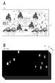
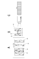
- FIG. 2A shows an example of an image that a person perceives as being of high quality
- FIG. 2B is an image in which the image is perceived by a person to be slightly deteriorated due to a reduction in the number of gradations, for example. There is.
- object detection when the image of FIG.
- FIG. 2A is analyzed by a neural network, a flower is erroneously determined to be a fish, while a flower is correctly regarded as a flower for the image of FIG. 2B. Making a decision.
- a flower is erroneously determined to be a fish, while a flower is correctly regarded as a flower for the image of FIG. 2B.
- Making a decision As can be seen from this example, in order to improve the accuracy of image recognition, it is desirable to perform image quality adjustment different from the image quality adjustment based on human aesthetics.
- the image quality suitable for such object detection does not depend on the image quality adjusted by a uniform parameter, but also on the object to be detected.
- a desirable image quality adjustment state differs between when detecting a person and when detecting an automobile. That is, the desired parameter values for image quality adjustment differ depending on the detection target.
- the classified image adaptation processing appropriate parameters (image quality adjustment values) are stored for each class of target objects. Then, for the image captured by the array sensor 2, object detection and class identification of the detected object are performed, parameters are selected and set in the logic unit 5 according to the identified class, and the logic unit 5 for the image , So that processing is performed according to the parameters.
- FIG. 3 is a part of the configuration of FIG. 1 extracted for the purpose of explaining the outline.
- the image pickup optical system 40 collects the subject light on the array sensor 2 to pick up an image.
- the obtained image signal G is processed by the logic unit 5, but is also supplied to the calculation unit 8.
- the object area recognition section 82 detects a candidate object and recognizes the object area.
- the object area recognition unit 82 also calculates a bounding box for a required object area.
- the class identification unit 83 classifies the detected object. When a plurality of objects or a plurality of types of objects are detected, class identification is performed for each and they are classified into each class. For example, in the case of the figure, class identification and classification are performed such that one object in the class “car”, five objects in the class “person”, and one object in the class “traffic signal”.
- the information of this class and the information of the bounding box are provided to the parameter selection unit 84, and the parameter selection unit 84 uses one of the parameter sets PR1, PR2, ... Select a set.
- the parameter set PR4 is selected.
- the parameter set is, for example, a set of a plurality of parameter values used in the processing of the logic unit 5, such as a gain setting value, a color correction coefficient, a gradation number, a compression rate, and a frame rate.
- the selected parameter set PR4 is set in the logic unit 5.
- the logic unit 5 performs various kinds of signal processing on the image signal G using each parameter shown in the parameter set PR4.
- the array sensor outputs all or any of data of output data (image signal, class, number of objects, presence / absence of target class, etc.) according to a request of the processor 11.
- the processor 11 can also send various instructions to the sensor device 1.
- the calculation unit 8 has a class identification function based on object detection (object category classification function), and the parameters of the logic unit 5 are adaptively set according to the output of the class identification unit.
- Classification image quality adaptation (parameter selection according to the target genre from object detection) is performed.
- appropriate parameters for each class are generated in advance by deep learning and stored in advance.
- a parameter set of the class “person” is generated, as shown in FIG. 4A, deep learning is performed using a large number of human images as learning data SD, and the image recognition rate is highest from the viewpoint of human recognition.
- a parameter set PR1 is generated.
- parameter sets PR2, PR3, ... With the highest image recognition rate are generated using deep learning.
- the parameter sets PR1, PR2, PR3, ... are stored so that the parameter selecting unit 84 can select them.
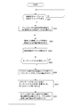
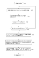
- FIG. 5 shows a process executed by the sensor device 1 (mainly the arithmetic operation unit 8) after the output of the image signal of one frame unit from the array sensor 2 is started in step S100.
- the processing of the calculation section 8 is processing executed by the respective functions of the key frame selection section 81, the object area recognition section 82, the class identification section 83, and the parameter selection section 84 shown in FIG. Note that this also applies to FIGS. 9, 14, 16, and 18 described later.
- step S101 the calculation unit 8 (key frame selection unit 81) performs a process of selecting a key frame at a timing according to the key frame selection algorithm.
- the sensor device 1 recognizes the class of the object to be imaged by selecting a key frame from the image signal in frame units which is the pixel array output signal of the array sensor 2 and performing image recognition.
- the selection of the key frame is performed by the key frame selection algorithm, whereby the still image (one frame) is selected.
- a keyframe selection algorithm there is a method of selecting one frame at every designated time interval. For example, one frame is set as a key frame at intervals of 30 seconds. Of course, 30 seconds is an example.
- a key frame as a timing according to an instruction from the outside of the sensor device 1 (processor 11 or the like). For example, it is assumed that the device in which the sensor device 1 is mounted is in accordance with an instruction from the device side. For example, in the case where the sensor device 1 is mounted on an automobile, the sensor device 1 is stopped in a parking lot, but a key frame is selected at a timing when the vehicle starts traveling. Also, the method of selecting the key frame may be changed depending on the situation. For example, when the sensor device 1 is mounted on an automobile, the interval between key frames is changed when the vehicle is stopped, during normal traveling, or during high-speed traveling.
- the calculation unit 8 detects the position of the object candidate in the key frame in step S102. That is, the calculation unit 8 searches for a candidate of an object to be detected in the image of the key frame, and obtains the position of one or a plurality of candidates (position coordinates in the image). For example, assume that the input image in FIG. 6A is a key frame. The calculation unit 8 detects a part that seems to be an object to be detected in this image. For example, the regions shown in FIGS. 6B and 6C are considered to be objects to be detected. This is a candidate for the object.
- step S103 of FIG. 5 the calculation unit 8 (class identification unit 83) classifies detected objects into classes. That is, each object candidate is classified and classified.
- a class is a category of objects recognized using image recognition. For example, as shown in FIGS. 6D and 6E, class identification such as “person” and “flower” is performed.
- the calculation unit 8 confirms whether or not the target class exists in the class obtained as the class identification result.
- the target class is a class specially set by the processor 11 among the classes. For example, when the target class is set to "person", the sensor device 1 enters the designated process when recognizing a person. It is desirable to be able to specify multiple target classes.
- step S103 when “person” and “flower” are set as the target classes, and “person” or “flower” exists in the class identified in step S103, the calculation unit 8 proceeds from step S104 to step S105. Proceed with processing. On the other hand, if the target class does not exist, the calculation unit 8 returns to step S101 and selects the next key frame.
- the calculation unit 8 calculates accurate position coordinates (bounding box) surrounding the object area classified into the class.
- the bounding box 20 is shown in FIGS. 6F and 6G.
- the bounding box 20 is defined by a minimum coordinate value Xmin and a maximum coordinate value Xmax as an area range on the X axis, and a minimum coordinate value Ymin and a maximum coordinate value Ymax as an area range on the Y axis.
- the calculation unit 8 selects a parameter set based on the class and number of objects and the area of the bounding box 20. For example, when there is one target class, the parameter set corresponding to that class is selected. When there are multiple types of target class objects on the screen, the following examples are possible. For example, it is conceivable to select a parameter set corresponding to the class having the largest number of objects in each class. Alternatively, when there are multiple types of target class objects on the screen, it is conceivable to select the parameter set corresponding to the class of the object having the largest bounding box 20 area.
- the screen when there are a plurality of types of target class objects on the screen, it is conceivable to select a parameter set corresponding to the class having the largest total area of the bounding box 20 for each class.
- the highest priority class is determined from the total number (or maximum value) of the number of objects in each class and the bounding box 20 area, and the corresponding class is handled. It is conceivable to select the parameter set to be used.
- there are various other parameter set selection methods but in any case, if the parameter set according to the dominant object in the screen or the class of the object to be detected with priority is selected. Good.
- step S107 the calculation unit 8 (parameter selection unit 84) performs a process of setting the selected parameter set in the logic unit 5.
- the logic unit 5 thereafter performs various image processes on the image signals of each frame that are sequentially input, using the set parameter set.
- the processed image signal, the set parameter, the information of the identified class, and the like are temporarily stored in the DRAM 6.
- step S108 the sensor device 1 outputs image information (still image, moving image), class identification information (class, number of objects, presence / absence of target class, etc.), used parameter set, and other information in response to a request from the processor 11. All or at least one will be output. That is, any of the information temporarily stored in the DRAM 6 is read and transmitted by the interface unit 7 in response to a request from the processor 11.
- the process of step S108 may be performed by the control of the arithmetic unit 8 or may be performed by accessing the DRAM 6 by the processor 11 via the interface unit 7. When the arithmetic unit 8 does not control the interface unit 7, the processing of the arithmetic unit 8 returns to step S101 after step S107.
- the processor 11 is supplied with the image signal having the parameter set according to the existence of the target class as the object included in the image.
- the image signal becomes an image signal subjected to image processing suitable for detecting the target class object. If the information on the detected class (target class) and the number of objects is also provided to the processor 11, it becomes useful information for the object detection processing by the processor 11.
- the processor 11 can perform highly accurate object detection. It should be noted that it is also possible to use the class setting within the sensor device 1 simply and to recognize it more finely outside. For example, the face recognition and the license plate recognition may be executed by the processor 11 without being executed by the sensor device 1. Further, in the processing example of FIG. 5, a portion that seems to be an object is detected in step S102 (FIGS.
- step S103 class identification is performed in step S103 (FIGS. 6D and 6E), and then the bounding box 20 is set in step S105. (FIGS. 6F and 6G), but the procedure is not limited to this.
- the procedure may be such that the bounding box 20 is set when an object-like portion is detected at the stage of step S102, then the class is identified at step S103, and if the target class exists, the process proceeds from step S104 to step S106.
- Second Embodiment Area Clipping> Area clipping will be described as a process of the second embodiment that can be executed by the sensor device 1 having the configuration of FIG.
- the image signal detected by the array sensor 2 it is usually considered that the information of all the pixels of each frame is transmitted to the processor 11 to execute the image recognition.
- the amount of transferred information remarkably increases as the resolution of the captured image by the array sensor 2 increases, and the transfer time increases. Will also be required.
- an increase in communication volume greatly affects communication cost and time.
- the load of the storage amount in the processor 11 and the cloud increases, the analysis processing load and the processing time increase, and the object detection performance decreases.
- the image signal is acquired or transferred at the pixel level of the area of the object after the next frame, and other areas are acquired.
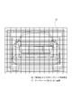
- FIG. 7A shows an image of a certain frame F1.
- ROI Region of Interest
- the image is an image including only the information of the ROI 21 as shown in FIG. 7B. Then, based on the image signal including such partial pixel information, the analysis in the calculation unit 8 is performed or the image is analyzed by being transferred to the processor 11.
- a certain frame F1 as a ratio of one in N frames is an image including information of all effective pixels.
- the calculation unit 8 scans the entire screen to detect the presence or absence and the position of the object.
- the ROI 21 is set.
- the image signal in which the AD conversion is performed only on the pixels of the ROI 21 that is the target area as illustrated in FIG. 8B is acquired.
- each square separated by a grid represents a pixel. In this way, for example, every N frames, one frame is subjected to full-screen scanning to detect the target object, and in the subsequent frames F2, F3, F4 ... I do.
- the amount of analysis data and the amount of communication data are reduced without lowering the accuracy of detecting the object that is the target of the application, the power consumption of the sensor device 1 is reduced, and the sensor device 1 is mounted.
- the image analysis related to the object detection of the entire system is accelerated.
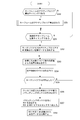
- FIG. 9 shows a processing example of the calculation unit 8 of the sensor device 1 as the area clipping analysis. A description will be given with reference to FIG. 10 sequentially.
- the calculation unit 8 determines in step S201 whether or not the object detection key frame recording timing has come.
- the object detection key frame recording timing means a timing at which information is acquired in all effective pixel areas of the array sensor 2 for object detection.
- the object detection key frame recording timing may be determined by a command from the outside of the sensor device 1 such as the processor 11, for example. For example, it is assumed that the object detection key frame recording timing is determined at intervals of 60 seconds in response to an instruction of 60 seconds.
- the calculation unit 8 proceeds to step S202 and acquires the image data AD-converted in all the effective pixel areas of the array sensor 2.
- the ADC / pixel selector 3 is caused to output the image signal of one frame from the array sensor 2 for the entire effective pixel area.
- step S203 the calculation unit 8 (object region recognition unit 82) detects a position that is a candidate for an object in the acquired image.
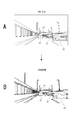
- the frame F1 is used as an object detection key frame, for example, the object candidate area 23 is detected in the image of the frame F1.
- the area including the images of "people" and “trees" is the candidate area 23.
- step S204 in FIG. 9 the calculation unit 8 (class identification unit 83) classifies the objects detected as candidates. For example, as shown in FIG. 10B, class identification such as “person” or “tree” is performed for the object in the candidate area 23.
- step S205 of FIG. 9 the calculation unit 8 confirms whether or not the target class exists in the class obtained as the class identification result. For example, when “person” is the target class, the target class exists as the identified class as shown in FIG. 10B. In such a case, the calculation unit 8 advances the process from step S205 to S206 in FIG. On the other hand, if the target class does not exist, the calculation unit 8 returns to step S201 and waits for the next object detection key frame recording timing.
- step S206 of FIG. 9 the calculation unit 8 (object region recognition unit 82) calculates the bounding box 20 of accurate position coordinates surrounding the area of the object classified into the target class.
- FIG. 10C shows an example of the bounding box 20 for the image of the person who is the target class. That is, the bounding box 20 is calculated as a more accurate area of the object corresponding to the target class.
- the calculation unit 8 calculates the ROI based on the bounding box 20.
- the ROI 21 and the bounding box 20 are shown in FIG. 10D.
- the ROI 21 is calculated by enlarging (ax ⁇ by) the vertical and horizontal sizes (x ⁇ y) of the bounding box 20.
- the enlargement scales a and b can be set vertically and horizontally, and the enlargement ratio may be fixed, but it is also conceivable that the enlargement ratio is specified from outside the sensor device 1 (for example, the processor 11 or the like).
- the calculation unit 8 transmits the ROI calculated in this way to the ADC / pixel selector 3.
- the ADC / pixel selector 3 AD-converts only the corresponding pixel in the ROI 21 of the array sensor 2 and outputs it.
- the calculation unit 8 acquires the image data of the next frame including the information of only the pixels in the ROI 21 in step S208 of FIG. Then, the processes of steps S203 and S204 are performed on the acquired frame.
- FIG. 10E schematically shows that only the pixels within the ROI 21 are AD-converted among all the effective pixels (the squares delimited by the grids in each drawing indicate the pixels).
- the calculation unit 8 detects the position of the object candidate and classifies the image of the frame F2 in steps S203 and S204 of FIG. 9.
- the bounding box 20 is newly calculated and the new ROI 21 is calculated based on the bounding box 20.
- the newly obtained ROI is shown as “ROI21 (NEW)”.
- the ROI 21 is generated by expanding the bounding box 20 in order to correspond to the movement of the object that is the subject (or the change in the subject direction of the imaging device). For example, the position of the person in frame F2 of FIG. 10E is changing to the right of the position of the person in frame F1 of FIG. 10A. However, since the ROI 21 is set wider, the possibility of acquiring the image of the target person in the frame F2 is increased even if only the pixels in the ROI 21 are acquired. As described above, the ROI 21 expands the bounding box 20 so that the target object can be detected even in the next frame.
- the expansion scales a and b are It is also possible to set it according to the frame rate. For example, when the frame rate is low, the frame interval time becomes long and the amount of movement of an object such as a person becomes large. Therefore, it is conceivable to make the ROI 21 wider than when the frame rate is high.
- recalculating the ROI 21 for each frame is also to cope with the movement of the object that is the subject (or the change in the subject direction of the imaging device). Due to the movement of the person, the person is detected at the rightward position in the ROI 21 from the image in FIG. 10F. Therefore, the bounding box 20 surrounding the area of the person is newly calculated and the ROI 21 is obtained, so that the ROI is updated so as to follow the movement of the person like ROI 21 (NEW).
- the calculation unit 8 notifies the ADC / pixel selector 3 of the new ROI 21 (NEW) in step S207. As a result, in the next frame, only the pixels in the new ROI 21 (NEW) are AD-converted (see FIG. 10G). Similarly, the calculation unit 8 acquires an image signal of only the information of the pixel in the ROI 21 (NEW) in step S208, and performs the processing in step S203 and subsequent steps.
- step S205 Such processing is repeated until it is determined in step S205 that the target class does not exist. Therefore, for example, by updating the position of the ROI 21 according to the person as the subject, even if the position of the person is moving as in the frame Fn in FIG. It is possible to acquire the image signal of the frame Fn including the information of the human region based on the ROI 21 calculated in (). If the detected person is framed out and cannot be detected, the target class cannot be acquired. Therefore, the calculation unit 8 returns from step S205 to step S201 and waits for the next object detection key frame recording timing.
- the image signal of the key frame at the object detection key frame recording timing includes the data of all effective pixels, but in the subsequent frame, only the pixels necessary for object detection are described.
- the image signal can have an extremely reduced amount of data, and is an image suitable for detection of a target object. Further, it is possible to reduce power consumption by reducing the number of read pixels in the array sensor 2.
- the ROI 21 is set for each object of one target class, and the area of the ROI 21 corresponding to each object is the read target from the array sensor 2, which is detected by the object detection key frame. It is limited to the object that was created. For example, even if a new object (for example, a person) appears as a subject at the timing of the frames F2 and F3, the image of the person may not be acquired. This is not a problem if it is used for purposes such as tracking and analyzing an object found in an object detection key frame with a certain time interval, but it is applied to, for example, a monitoring system that monitors all people who appear as subjects.
- step S205 an object that appears in a frame other than the object detection key frame also needs to be detected. Therefore, for example, even if the detection of the object of the target class is continued (that is, even if the determination of “YES” is continued in step S205), the process always returns to step S202 at a predetermined time interval, and the image of all effective pixels is displayed. It is conceivable to acquire a signal. It is also preferable that the processor 11 or the like can specify the time interval for acquiring the image signals of all effective pixels.
- the peripheral portion of the image may be always set as an AD conversion target area separately from the ROI 21, and when an object is newly framed in, the object is detected and the ROI 21 can be set for the object. Conceivable.
- the ROI 21 is described as an example in which the bounding box 20 is enlarged to form a rectangular area, but the ROI 21 is not limited to the rectangular area.
- semantic segmentation or object area detection at the pixel level, may be used to calculate the ROI 21 from the area of the object of that target class.
- FIG. 11 shows a ROI 21 based on semantic segmentation.
- the non-rectangular ROI 21 is set by expanding the pixel area as an object (for example, a person).
- a rectangular ROI 21 may not be included in part or may be too large, such as a track with a protrusion or a person riding a bicycle. If the non-rectangular ROI 21 is generated according to the object position at the pixel level, it is possible to increase the possibility that the ROI 21 can achieve both reduction of the data amount and acquisition of necessary information.
- the AROI is an ROI set using a template set according to the class.
- the power consumed by photoelectric conversion is the largest. Therefore, in order to reduce power consumption, it is desirable to reduce the number of pixels that undergo photoelectric conversion as much as possible.
- the image signal obtained by the array sensor 2 is for image analysis and is not viewed by a person, it is not necessary for the person to see and recognize it or to obtain a clean image. In other words, it is important that the image be an object that can be accurately detected. For example, in the above-described second embodiment, class identification is performed on the detected object, but if class identification is performed in this way, the minimum area for recognition corresponding to the class is set as the ROI. It would be good to do so. Therefore, the AROI 22 as shown in FIGS. 12 and 13 is set.
- FIG. 12 shows the AROI 22 generated using the template corresponding to the class “person” for the image area of the person.
- the grid in the figure is a pixel (pixel), and the dark pixel is a pixel designated by the AROI.
- the template corresponding to the class “person” has a high density of required pixels for the face portion and a low density of required pixels for the body portion so that the entire body can be covered.
- FIG. 13 shows an AROI 22 generated by using a template corresponding to the class “car”. In this example, it is adapted to the rear image of the automobile, and for example, the portion where the license plate is located has a high density of required pixels, and other than that, the required pixels are arranged at a low density to cover the whole.
- the "person” class is also subdivided, and the template is subdivided into “sideways person”, “frontward person”, “sitting person”, etc., or “side image” for the “automobile” class. It is also possible to subdivide the template into "front image”, “rear image”, and the like.
- the template is selected according to the class, and the template is scaled according to the area size in the actual frame to generate the AROI22.
- steps S201 to S206 are the same processes as in FIG.
- the calculation unit 8 calculates the bounding box 20 in step S206. Then, in step S210, the calculation unit 8 (parameter selection unit 84) selects a template for AROI that is calculated and stored in advance based on the class. For example, if “person” is the target class and there is a person in the image, the template for “person” is selected.
- step S211 the calculation unit 8 (object region recognition unit 82) calculates the AROI 22 based on the bounding box 20. For example, an AROI 22 is obtained by adjusting the size of the template according to the size of the bounding box 20. Then, the calculation unit 8 (object region recognition unit 82) transmits the AROI 22 (AROI pattern and region) to the ADC / pixel selector 3.
- the ADC / pixel selector 3 AD-converts only the corresponding pixel in the AROI 22 of the array sensor 2 and outputs it.
- the calculation unit 8 acquires the image data of the next frame including the information of only the pixels in the AROI 22 in step S212. Then, the processes of steps S203 and S204 are performed on the acquired frame. The subsequent process flow is the same as that described with reference to FIG.
- the AROI 22 By generating the AROI 22 using the template set according to the class in this way, it is possible to obtain information that enables accurate object detection according to the class even if the number of pixels to be photoelectrically converted is significantly reduced. it can. Note that it is necessary to ensure that the object detection keyframe recording timing mentioned in the second embodiment occurs at a certain time interval, or to keep the peripheral portion of the image as an AD conversion target area. It can also be applied to the third embodiment. Further, by performing the area clipping using the AROI 22 of the third embodiment described above and the classified image adaptation processing of the first embodiment in combination, the effect of reducing the amount of data and improving the detection accuracy is further improved. You can get it effectively.
- the intelligent compression is to specify an object to be detected and apply compression to the object at a low compression rate, and to compress other objects at a high compression rate.
- FIG. FIG. 15A shows a state in which the ROI 21 is generated corresponding to the region of each automobile when the class of the automobile, which is the target class, is detected from the image of one frame.
- FIG. 15B shows an image signal obtained by compressing the ROI 21 area at a low compression rate and the other areas at a high compression rate.
- FIG. 16 shows an example of processing for performing intelligent compression. Note that steps S201 to S206 are the same processes as in FIG. However, since the circumstances are slightly different from the case of the area clipping described above, these processes will also be referred to.
- the calculation unit 8 determines in step S201 whether or not the object detection key frame recording timing has come. When the object detection key frame recording timing comes, the calculation unit 8 proceeds to step S202 and acquires the image data AD-converted in all the effective pixel areas of the array sensor 2. However, in the case of intelligent compression, the ADC / pixel selector 3 reads (AD conversion) the signals of all pixels from the array sensor 2 every frame.
- the calculation unit 8 (object region recognition unit 82) detects a position that is a candidate for an object in the image acquired in step S201. Then, in step S204, the calculation unit 8 (class identification unit 83) performs class classification of the objects detected as candidates. In step S205, the calculation unit 8 confirms whether or not the target class exists in the class obtained as the class identification result.
- the calculation unit 8 calculates the bounding box 20 in step S206 when an object of the target class exists in the image signals of all effective pixels obtained at the object detection keyframe recording timing.
- step S220 the calculation unit 8 (object region recognition unit 82) calculates the ROI 21 based on the bounding box 20. Also in this case, for example, the bounding box 20 may be enlarged to set the ROI 21. The calculation unit 8 (object region recognition unit 82) transmits the ROI 21 calculated in this way to the logic unit 5.
- step S221 the logic unit 5 has a low compression rate for the pixel area corresponding to the ROI 21 and a high compression rate for the other pixel areas with respect to the image signal read from the array sensor 2. Perform compression processing.
- the compressed image signal is then written in the DRAM 6 and transferred to the processor 11 by the interface unit 7.
- the necessary area designated by the ROI 21 has a low compression rate, and sufficient information exists, which enables accurate object detection.
- step S203 As the process of the calculation unit 8, after step S220, the process returns to step S203, the position of the object candidate for the next frame is detected, and the class of the detected object is identified in step S204.
- reading from the array sensor 2 is performed for all effective pixels in each frame. Therefore, even when the process returns to step S203 after steps S220 and S211, the calculation unit 8 performs the steps.
- S203 it is possible to scan the range of all effective pixels to detect object candidates. By scanning the range of all effective pixels and detecting object candidates, it is possible to always cope with the appearance of a new target class object during the key frame recording timing. However, in this case, if the calculation unit 8 detects the object candidates only in the area within the ROI 21, the processing load on the calculation unit 8 can be reduced.
- the computing unit 8 updates the ROI 21 in steps S206 and S220 in response to the presence of the target class being confirmed. Therefore, the area compressed at a low compression rate in the logic unit 5 is also updated according to the position of the object in each frame.
- step S205 If it is determined in step S205 that the target class does not exist, the processing of the calculation unit 8 returns to step S202 and waits for the object detection keyframe recording timing.
- intelligent compression processing is performed in which a portion required for analysis, that is, the ROI 21 in which the object of the target class exists is compressed at a low compression rate, and the compression processing is performed at a high compression rate other than that. Will be seen.
- the object detection key frame recording timing mentioned in the second embodiment is always generated at a certain time interval and the ROI based on the semantic segmentation is generated in the fourth embodiment. Applicable.
- the intelligent compression processing of the fourth embodiment described above and the classified image adaptation processing of the first embodiment in combination the effect of reducing the data amount and improving the detection accuracy is made more effective. Obtainable.
- Active sampling will be described as a process of the fifth embodiment that can be executed by the sensor device 1 having the configuration of FIG. 1. Active sampling refers to the process of dynamically changing the frame rate depending on the presence or absence of an object. It can be said that this is compression of the amount of data in the time axis direction depending on the presence or absence of an object. Further, it is possible to reduce the power consumption of the sensor device 1.
- FIG. 17A shows a state in which no person is included in the captured image.
- the frame rate is set to a low rate, for example, 1 fps.
- FIG. 17B shows a state in which a person is detected in the captured image. In such a case, the frame rate is changed to a high rate, for example, 100 fps.
- the frame rate is lowered when it is not particularly necessary (when a person is not detected), and when it is necessary (when a person is detected). ) Increases the frame rate to make the amount of information dense.
- FIG. 18 shows an example of active sampling processing.
- the calculation unit 8 (keyframe selection unit 81) sets the ADC / pixel selector 3 to capture a moving image in accordance with, for example, the setting of the idling mode stored in the calculation unit 8 in advance.
- the setting of the idling mode and the setting of the normal mode are stored in the parameter selection unit 84 in the calculation unit 8.
- the active sampling is provided with an idling mode and a normal mode.
- the idling mode is a mode before it is determined that an object of the target class is in the image pickup screen. In this idling mode, a moving image is captured at a frame rate slower than in the normal mode. It is considered that the idling mode is started by a command from the outside of the sensor device 1. Further, the idling mode may be made to respond to an instruction of the idling mode data acquisition timing interval from the outside of the sensor device 1. For example, when there is an instruction for 60 seconds, the object detection key frame recording timing is set at intervals of 60 seconds.
- the normal mode is a normal moving image capturing mode. For example, it responds to a command for the data acquisition timing interval for normal mode from the outside of the sensor device 1. Normally, a moving image is shot at a frame rate faster than that in the idling mode. For example, when an instruction of 0.01 sec is given, the mode is set to take an image at an interval of 0.01 sec (100 fps).
- the moving image capturing is performed at, for example, 1 sec intervals.
- the setting of the idling mode and the setting of the normal mode are not necessarily stored in the calculation unit 8, but may be stored in an external memory of the calculation unit 8.
- the frame rates in idling mode and normal mode are examples. Further, it is desirable that the set values of the idling mode and the normal mode can be rewritten by an external device such as the processor 11.
- step S302 the calculation unit 8 (object region recognition unit 82) detects a position that is a candidate for an object in the acquired image.
- step S303 the calculation unit 8 (class identification unit 83) classifies the objects detected as candidates.
- step S304 the calculation unit 8 confirms whether or not the target class exists in the class obtained as the class identification result. If the target class does not exist, the arithmetic unit 8 performs the processes of steps S301, S302, and S303. That is, the image of the next frame in the idling mode is acquired, and similarly, the position as a candidate of the object is detected and the class is identified. In this case, assuming that the image is captured at 1 fps, for example, these processes are performed on the image after 1 second.
- the calculation unit 8 advances the process from step S304 to S305.
- the calculation unit 8 (key frame selection unit 81) sets the moving image capturing to the ADC / pixel selector 3 according to the stored normal mode setting, and instructs the ADC / pixel selector 3 to capture the normal mode. Therefore, if the normal mode is set to 100 fsp, moving image capturing is performed at intervals of 0.01 sec, for example.
- the arithmetic unit 8 performs the processes of steps S302 and S303 in the state where the mode is switched to the normal mode.
- the normal mode is continued, while if the target class does not exist, the process returns to step S301 and the idling mode is switched to.
- the processing as active sampling is performed as described above. This reduces the frame rate and compresses the amount of data, especially during the period when the target class does not exist, thereby reducing power consumption.
- the arithmetic unit 8 is configured to instruct the ADC / pixel selector 3 to change the frame rate and change the frame rate, the arithmetic unit 8 may instruct the logic unit 5 to convert the frame rate. For example, reading from the array sensor 2 is always performed at 100 fps, and in the idling mode, the logic unit 5 is instructed to perform frame thinning. This makes it possible to reduce the amount of data regarding the transmission to the processor 11.
- a parameter used in the image processing in the logic unit 5 is assumed, and the parameter of the image processing used in the logic unit 5 is set so as to satisfy a threshold value set in the sensor device 1 ( Be adjusted and changed). Further, as parameters, parameters used for image reading processing such as signal reading by the ADC / pixel selector 3 and exposure operation by the array sensor 2 are also assumed. The control parameters of the image pickup processing operation of the ADC / pixel selector 3 and the array sensor 2 are set (adjusted / changed) so as to satisfy the threshold value set in the sensor device 1, for example.
- the parameter used in the logic unit 5 is selected according to the class identification, but it is assumed that the selected parameter is set (adjusted / changed) based on the threshold value. You can also Alternatively, it is conceivable that the parameter is not limited to the parameter selected based on the class identification, and that the parameter used in the logic unit 5, the ADC / pixel selector 3 or the array sensor 2 is set based on the threshold value. To be
- parameters relating to the imaging processing are exemplified as follows. -Image aspect ratio-Resolution-Number of color gradations (number of colors or bits) ⁇ Contrast adjustment value ⁇ Sharpness adjustment value ⁇ Gray level adjustment value ⁇ Gamma correction value ⁇ Sampling rate conversion ratio
- the parameters of the aspect ratio and resolution of the image are also reflected in the ROI 21.
- the number of color gradations, contrast adjustment value, sharpness adjustment value, gray level adjustment value, gamma correction value, and resolution are parameters relating to image quality.
- the sampling rate conversion ratio is a parameter of time resolution.
- the sampling rate and the resolution for example, the resolution set when the ADC / pixel selector 3 is read
- Shutter speed of array sensor 2 exposure time
- the setting according to the threshold value of such a parameter is, for example, when the processor 11 performs object detection based on learning using a deep neural network (DNN: Deep Neural Network), a practical accuracy for the output of the object detection.
- DNN Deep Neural Network
- a practical accuracy for the output of the object detection In order to reduce the amount of data, speed up processing, and reduce power consumption while ensuring the above. That is, parameters such as the resolution and the number of colors are changed to reduce the amount of image pickup data, but the accuracy of object detection can be maintained at a necessary level also by this.
- the confidence rate is the ratio of certainty that an object can be correctly identified and detected.
- the confidence rate is changed by changing parameters relating to image pickup or image quality such as resolution, number of colors, and temporal resolution of image data to be analyzed. That is, the accuracy of image analysis and object detection changes.
- the confidence rate for object detection has never been higher, but in reality, the highest rate is not always required.
- the degree of accuracy is not required.
- the confidence rate CR required as the accuracy of object detection varies depending on various factors such as the purpose of detection, target, type of device / application program, time, and area. Furthermore, the confidence rate varies depending on the analysis ability of the processor 11 and the degree of learning, and also varies depending on the detection target and class. From these facts, it is possible to output an image signal that meets requirements for object detection and the like by determining a threshold value based on an appropriate required confidence rate and changing the parameter accordingly.
- parameters that are equal to or higher than the threshold 0.80 as the confidence rate CR are calculated, and the parameters used in the logic unit 5 and the like are set.
- the "threshold” may be considered as a required value as a confidence rate, but in the sense of a threshold calculated for parameter adjustment, a parameter for obtaining a required confidence rate as a "threshold”. It can also be thought of as the value of.
- the processing of “setting a threshold value of a parameter and performing processing using the parameter set based on the threshold value” is a processing method such as the following [1] and [2]. Is assumed. [1] Calculating a threshold value of an index value such as a confidence rate suitable for a usage mode or a usage environment, and setting a parameter to be actually used as a parameter value that gives an index value exceeding the threshold value of the index value.
- the threshold value of the parameter is set from the viewpoint of the index value of object detection.
- a threshold value of a parameter for obtaining a required value as an index value such as a confidence rate is calculated, and a parameter actually used is set based on the threshold value. That is, the threshold value of the parameter is set in terms of the value of the parameter itself.
- a threshold is set as in the above [1] or [2] based on the confidence rate, and the parameters actually used are parameters adapted so that the image data amount is as small as possible.
- a parameter is calculated in real time (for example, periodically during imaging), and the parameter is dynamically changed. For example, by calculating an appropriate threshold value or a parameter corresponding to it by DNN processing according to the application of the sensor device 1, the target class or the imaging environment, and changing the parameter, speedup and power consumption reduction adapted to the application or the like, Perform high precision.
- the parameter adjustment is performed by setting a threshold value based on the confidence rate of object detection, and calculating a parameter set value that is as close to the threshold value as possible and does not fall below the threshold value. I shall.
- FIG. 20A shows an image classified as a “human face” as a class
- FIG. 20B shows an image classified as a “road sign (sign)” as a class.
- the image on the right side is not appropriate, and the parameter of the central image is appropriate as the parameter setting.
- any image is appropriate.
- the parameter of the image on the right is suitable for the parameter setting.
- the detection accuracy and the required accuracy for the image signal quality differ depending on the object class as described above, it is appropriate to set threshold values and change parameters according to the class.
- FIG. 21 shows a configuration example of the sensor device 1.
- the same components as those in FIG. 1 are designated by the same reference numerals to avoid redundant description.
- the configuration of FIG. 21 is different from that of FIG. 1 in that a threshold setting unit 85 is provided as an arithmetic function in the arithmetic unit 8 configured as, for example, an AI processor.
- the threshold setting unit 85 has a function as a DNN engine, and regards all or some of the parameters used for the image processing of the logic unit 5 or the imaging processing (processing of the array sensor 2 and ADC / pixel selector 3) related to imaging by the array sensor 2. , And sets the threshold value of the parameter.
- the threshold value setting unit 85 causes all or part of the logic unit 5, the array sensor 2, and the ADC / pixel selector 3 to perform processing using the parameter changed based on the threshold value.
- the threshold setting unit 85 changes, for example, a parameter used for image processing in the logic unit 5 based on the threshold, and sets the changed parameter in the logic unit 5.
- the threshold value setting unit 85 changes the parameters used for the imaging operation such as the exposure operation in the array sensor 2, the reading process of the ADC / pixel selector 3, and the AD conversion process based on the threshold value, and the changed parameter is used. Are set in the array sensor 2 and the ADC / pixel selector 3.
- FIG. 22 shows a processing example of the calculation unit 8 of such a sensor device 1.
- FIG. 22 shows an example in which the processing of the threshold setting unit 85 described above is added to the classification image adaptation processing of FIG.
- the same processes as those in FIG. 5 are designated by the same step numbers and the description thereof will be omitted. 22, it is assumed that steps S150 and S151 as processing by the threshold value setting unit 85 are added to the processing of FIG.
- step S150 the calculation unit 8 determines whether or not it is the threshold value calculation timing. If the threshold value calculation timing, the process proceeds to step S151. If not, the process proceeds to step S101.
- the threshold calculation timing is, for example, the following timing. a. Every predetermined time interval: For example, every one hour interval from the start of imaging b. Every predetermined set time: For example, every 0:00 am time c. Every time a predetermined target class appears: For example, every time the target class appears 1000 times d. Every predetermined target class imaging time: For example, every 5 hours when the target class is imaged e. Timing according to an instruction from the outside: an instruction from a device / device side in which the sensor device 1 is mounted, such as the processor 11
- the calculation unit 8 calculates the threshold value according to the threshold value calculation policy in step S151. That is, the threshold value is determined and the parameter corresponding to the threshold value is set.
- This threshold calculation policy (threshold) is divided into several policies depending on the type and way of capturing parameters of the imaging process or image processing to be noted when calculating the threshold, and it differs depending on the application. An example is given below.
- the inflection point of the downward curve of the confidence rate If the resolution is decreased, the data size will decrease and the calculation cost will also decrease, but in general, the confidence rate will decrease.
- the horizontal axis represents the resolution and the vertical axis represents the confidence rate.
- the decrease in the confidence rate greatly decreases when the resolution becomes lower than a certain resolution (inflection point). Therefore, for example, the inflection point of the curve of the relationship between the confidence rate and the resolution is obtained while changing the resolution.
- the inflection point or the vicinity of the inflection point is considered as a threshold value and parameters are set so as to reduce the resolution.
- the classification rate for object detection does not necessarily mean that the confidence rate is higher when the number of colors is larger, but there is an optimum number of colors that maximizes the confidence rate depending on the target class.
- the horizontal axis shows the number of color gradations, and the vertical axis shows the confidence rate.
- the maximum value (the peak of the curve of the relationship between the confidence rate and the number of color gradations) is considered as a threshold value, or a predetermined range close to the maximum value (a value obtained by decreasing the confidence rate of a predetermined percentage) is considered as a threshold value. Then, the parameter of the number of color gradations is set according to the threshold value.
- the parameter setting that enables N-hour imaging is obtained, and the parameter is set so that the confidence rate becomes the highest (or a predetermined value or more). For example, it is conceivable that the threshold value such as the confidence rate is lowered according to the remaining battery amount and the parameter setting is performed according to the confidence rate so that the imaging time can be obtained as long as possible.
- Object tracking using time resolution capable of maintaining object tracking is to recognize a specific detected object (object) in a frame traveling direction by tracking recognition in a frame of continuous image signals.
- the time resolution of the image signal is lowered, the calculation cost for object tracking becomes high.
- the parameter that can maintain the object tracking is used as a threshold value, and the time resolution and other parameters are determined in order to reduce the calculation cost of the object tracking.
- FIG. 24 shows an example of the threshold value calculation processing of the calculation unit 8.
- the processing of the calculation unit 8 in FIG. 24 is processing executed by the functions of the object area recognition unit 82, the class identification unit 83, and the threshold value setting unit 85 shown in FIG.
- the arithmetic unit 8 acquires an image signal in 1-frame units from the array sensor 2 in step S160.
- step S161 the calculation unit 8 (object region recognition unit 82) detects a position that is a candidate for an object in the acquired frame. That is, the calculation unit 8 searches for a candidate of an object to be detected in the frame image, and obtains the position of one or a plurality of candidates (positional coordinates within the image).
- step S162 the calculation unit 8 (class identification unit 83) classifies detected objects into classes. That is, each object candidate is classified and classified.
- step S163 the calculation unit 8 confirms whether or not the target class exists in the class obtained as the class identification result.
- the target class is, for example, a class set by the processor 11 as described above. That is, a class that is the target of object detection by the processor 11 is assumed.
- the calculation unit 8 returns to step S160 and acquires the image data of the next frame. If the target class exists, the calculation unit 8 advances the process from steps S163 to S164.
- the calculation unit 8 calculates accurate position coordinates (bounding box 20) surrounding the object area classified into the class.
- the bounding box 20 is as described with reference to FIGS. 6F and 6G.
- step S165 the calculation unit 8 (threshold value setting unit 85) changes the parameters used in the image capturing process or the image process for the target class surrounded by the bounding box 20 according to the preset threshold calculation policy while changing the threshold and the parameter. To calculate.
- step S166 the calculation unit 8 (threshold value setting unit 85) records the information of the threshold value, the parameter, the target class, and the threshold value calculation policy calculated in step S165 in association with each other. For example, it is recorded in a recording area inside the arithmetic unit 8, is recorded in a predetermined area of the memory 6, or is transferred to the processor 11 and recorded. As a result, thresholds and parameters according to the target class are set.
- step S151 of FIG. 22 the threshold and parameters are set as described above, for example. Therefore, the parameter set for a certain target class is changed every time the threshold value calculation timing is reached. For example, if the person is the target class, all or some of the parameters of the parameter set corresponding to the person are changed according to the threshold value.
- steps S101 to S107 in FIG. 22 are the same as those in FIG. 5, in this case, the parameter set is selected according to the target class. Then, in step S107, the parameter set is set in the logic unit 5.
- the parameter set set in the logic unit 5 is a parameter set adapted to the target class, but is a parameter set changed based on the threshold value calculated in the process of step S151.
- the arithmetic unit 8 (threshold value setting unit 85) performs necessary processing, for example, transfer of a parameter to the logic unit 5 or a change instruction so that the parameter used in the logic unit 5 is changed in this way.
- the parameters relating to the image processing and the imaging processing are set to values that reduce the image data amount as much as possible based on the threshold value. Therefore, the image signal output from the interface unit 7 can have an image quality or the like that can maintain the accuracy of object detection required by the processor 11, and can have a small amount of data.
- processing example of FIG. 22 described above adds the concept of parameter change based on the threshold setting to the classification image adaptation processing of FIG. 5, but may not necessarily be combined with the classification image adaptation processing.
- a processing example of only steps S150, S151, S107, and S108 processing example in which steps S101 to S107 are omitted in FIG. 22 is also conceivable.
- the parameters used in the image processing in the logic unit 5 or the parameters used in the imaging processing used in the array sensor 2 or the ADC / pixel selector 3 are set based on the threshold value calculation in step S151. Then, at the time of step S107, the parameter set according to the threshold value is set in the logic unit 5, the array sensor 2, and the ADC / pixel selector 3. That is, the calculation unit 8 (threshold value setting unit 85) transfers the parameter set according to the threshold value to a part or all of the logic unit 5, the array sensor 2, and the ADC / pixel selector 3, or issues a change instruction. To do.
- the parameters set by default in the logic unit 5, the array sensor 2, the ADC / pixel selector 3, for example, are sequentially changed based on the threshold value calculation without depending on the idea of using the parameter set according to the class. Processing that will be performed will be realized.
- FIG. 25 is a configuration example in which the arithmetic unit 8 is provided separately from the sensor device 1 as the terminal device 100.
- the calculation unit 8 is provided in the terminal device 100 as a chip separate from the sensor device 1, and can communicate with the sensor device 1 via the interface unit 7.
- the calculation unit 8 includes a threshold value setting unit 85 that serves as a DNN engine for setting a threshold value.
- the arithmetic unit 8 in FIG. 25 can also perform the same processing as in the case of FIG.
- the calculation unit 8 may be separate from the sensor device 1.
- the configuration example of FIG. 26 is an example in which the threshold value calculation unit 85 serving as a DNN engine for setting the threshold value is formed by a processor or the like independent of the sensor device 1 and the calculation unit 8.
- the terminal device 100 has a configuration including the sensor device 1 (including the calculation unit 8), the processor 11, the external sensor 12, and the threshold value setting unit 85.
- the threshold value setting unit 85 can communicate with the sensor device 1 via the interface unit 7, and can perform the same processing as that in FIG. 22 in cooperation with the calculation unit 8.
- the sensor device 1 and the calculation unit 8 may be configured separately as shown in FIG. 26, and the threshold value setting unit 85 may be configured by a separate processor.
- the key frame selection unit 81, the object area recognition unit 82, the class identification unit 83, the parameter selection unit 84, and the like are also arranged outside the sensor device 1 or outside the calculation unit 8 similarly to the threshold setting unit 85. It is also conceivable that the configuration is changed. This point can also be applied as a modification of the configuration of FIG.
- Seventh Embodiment Active Area Clipping>
- the ROI of the above-described second embodiment is used to realize more efficient processing.
- the processing of the following seventh embodiment can be applied to any of the configurations shown in FIGS. 1, 21, 25, and 26.
- the ROI 21 is set for the detection target object as illustrated in FIG. 7 and FIG. 8 and only the pixels within the area designated as the ROI 21 are read from the array sensor 2 Said. It should be noted that the area defined as the ROI 21 may be concentrated on a specific area in the image.
- FIG. 27A exemplifies an image of a surveillance camera in a building, for example. It is assumed that the ROI 21 is set with a person as a detection target.
- the figure shows the position in the image of the bounding box 20 that is the source of the ROI 21 set within the past predetermined period.
- the set position of the bounding box 20 (and the ROI 21) is an area near the floor in the image within the past predetermined period. In other words, since no person appears in the area near the ceiling in the image, it can be said that the person detection process does not have to be performed for the image area near the ceiling.
- the area where the “person” to be detected appears that is, the area where the bounding box 20 is set in the past predetermined period is set as the active area RA
- the “person” to be detected is An area that does not appear, that is, an area where the bounding box 20 has not been set in the past predetermined period is set as an inactive area DA.
- FIG. 28A shows an example of an image of a surveillance camera that monitors a vehicle as a detection target on a highway, for example, and shows the position of the bounding box 20 set in the past predetermined period. In this case as well, the vehicle appears near the road surface, so that the active area RA and the inactive area DA can be set as shown in FIG. 27B.
- the active area RA is set as in the examples of FIGS. 27B and 28B described above, and the object detection is performed from the detection signal of the active area RA in the imaging pixel by the array sensor 2. Then, the ROI 21 generated based on the detection of the object is instructed to the signal processing unit 30 as an area related to acquisition of the detection signal or signal processing of the detection signal, as in the second embodiment.
- the object detection key frame is a frame in which information is acquired in all effective pixel areas of the array sensor 2 for object detection in the processing of the second embodiment. In the key frame, acquiring information only in the pixel area of the active area RA is the processing of the seventh embodiment.
- FIG. 29 shows a processing example of the calculation unit 8. The same steps as those in FIG. 9 are designated by the same step numbers.
- step S250 the operation unit 8 determines whether or not it is the calculation timing of the active area for the key frame. If the calculation timing is reached, the process proceeds to step S161. If it is not the threshold value calculation timing, the process proceeds to step S201.
- the calculation timing of the active area RA for the key frame may be as follows. a. Every predetermined time interval: For example, every one hour from the start of imaging b. Every predetermined set time: For example, every 0:00 am time c. Every time a predetermined target class appears: For example, every time the target class appears 1000 times d. Every predetermined target class shooting time: every time the target class is imaged for 5 hours e. Timing according to an instruction from the outside: an instruction from a device / device side in which the sensor device 1 is mounted, such as the processor 11
- step S161 the calculation unit 8 calculates the active area RA for the key frame.
- step S271 the calculation unit 8 (object region recognition unit 82) determines that the bounding box 20 of the target class has appeared within the past predetermined period on the array sensor 2. Calculate the pixels in the appearance area of. In this case, all the pixels in each of the appearing bounding boxes 20 become the pixels of the appearance area, but a range is set so as to envelop all the appearing bounding boxes 20, and all the pixels in the range are set. It should be a pixel in the appearance area. Further, a range in which all the appearing bounding boxes 20 are envelope-enclosed may be expanded in the circumferential direction, and all pixels in the range may be used as pixels in the appearing area. The pixel range including all the appearance areas of the bounding box 20 calculated in this way becomes the active area RA.
- step S272 the calculation unit 8 (object region recognition unit 82) records the calculated pixel area together with the class name as the active area RA for the key frame. For example, it is recorded in a recording area inside the arithmetic unit 8, is recorded in a predetermined area of the memory 6, or is transferred to the processor 11 and recorded. Thereby, the active area RA according to the target class is set.
- the calculation unit 8 determines whether or not the object detection key frame recording timing has come in step S201.
- the object detection keyframe recording timing is the timing at which information is acquired from the array sensor 2 for object detection.
- the object detection key frame recording timing may be determined by a command from the outside of the sensor device 1 such as the processor 11, for example. For example, it is assumed that the object detection key frame recording timing is determined at intervals of 60 seconds in response to an instruction of 60 seconds.
- the calculation unit 8 proceeds to step S252, and acquires the AD-converted image data of the pixels of the active area RA of the array sensor 2.
- the ADC / pixel selector 3 is made to output the image signal of one frame from the array sensor 2 for the active area RA.
- step S203 the calculation unit 8 (object region recognition unit 82) detects a position that is a candidate for an object in the acquired image.
- the steps S203 to S208 are the same as those in FIG.
- the object detection in step S203 can be performed only in the active area RA instead of in the entire effective pixel area of one frame.
- the active area RA is an area where the target class object may be detected.
- the area other than the active area RA is an area in which object detection of the target class is almost impossible. Therefore, by reducing the number of read pixels of the object detection key frame and reducing the detection range, it is possible to realize processing efficiency and power consumption reduction.
- the active area RA is set based on the history of the bounding box 20, but the active area RA may be set based on the history of the ROI 21. In that case, it is possible to include a history of pixel positions of the ROI (ROI 21 (NEW) described in FIG. 10) that moves for each frame.
- the threshold value of the sixth embodiment is determined based on the correct rate of object detection calculated by DNN, and the parameter is set.
- the distribution of the resolution of the attention area in the AROI 22 is determined according to the threshold value set using the confidence rate.
- An example is schematically shown in FIG. Consider the case where people are the target class and the case where faces are the target class.
- the second resolution is selected as a parameter adapted so that the image data amount is as small as possible, and image processing is performed on pixels in the template.
- the threshold thP for human detection is 0.80
- the second resolution is selected as a parameter adapted so that the image data amount is as small as possible, and image processing is performed on pixels in the template.
- the second resolution is suitable for both cases, but in some cases, the threshold thF is set to 0.94 for the face detection and the first resolution is set to 0.60 for the person detection. It is also conceivable that the third resolution will be set.
- a threshold value is set for each target class, and parameters such as image processing and readout processing for pixels in the AROI 22 are set.
- FIG. 32 shows a processing example of the calculation unit 8. Steps S250 and S251 of FIG. 32 are the same as steps S250 and S251 of FIG. 29, and the calculation unit 8 calculates the active area RA (processing of FIG. 30) at the detection timing of the active area RA of the key frame.
- Steps S260 and S261 are the same as steps S150 and S151 of FIG. That is, in step S260, the calculation unit 8 (threshold value setting unit 85) determines whether or not it is the threshold value calculation timing, and if it is the threshold value calculation timing, the threshold value calculation (the process of FIG. 24) is performed in step S261.
- the calculation unit 8 determines whether or not it is the threshold value calculation timing, and if it is the threshold value calculation timing, the threshold value calculation (the process of FIG. 24) is performed in step S261.
- the calculation unit 8 (object region recognition unit 82) performs steps S160 to S164 as described above. Then, in step S165, the calculation unit 8 (threshold value setting unit 85) changes the resolution of the target class surrounded by the bounding box 20 and sets a threshold value based on the confidence rate from the data of the pixel area corresponding to the AROI pattern as the template. Is calculated and the parameter is set based on the threshold.
- the parameters are set according to the threshold value for the AROI pattern as the template according to the class. For example, the resolution for the area on the AROI pattern is set.
- step S166 information about the threshold, the target class, the AROI pattern, the necessary parameters, and the threshold calculation policy is recorded in association with each other. For example, it is recorded in a recording area inside the arithmetic unit 8, is recorded in a predetermined area of the memory 6, or is transferred to the processor 11 and recorded.
- step S201 of FIG. 32 the calculation unit 8 determines whether or not the object detection key frame recording timing has come, and when the object detection key frame recording timing has come, the calculation unit 8 proceeds to step S252 and activates the array sensor 2.
- the image data AD-converted for the pixels in the area RA is acquired.
- the ADC / pixel selector 3 is made to output the image signal of one frame from the array sensor 2 for the active area RA.
- step S203 the calculation unit 8 (object region recognition unit 82) detects a position that is a candidate for an object in the acquired image.
- the steps S203 to S206 are the same as those in FIG.
- the calculation unit 8 (parameter selection unit 84) selects the AROI pattern calculated and recorded based on the threshold value in step S262.
- the calculation unit 8 (object region recognition unit 82) calculates the actual AROI 22 based on the bounding box 20. That is, the actual pixel area corresponding to the selected AROI pattern is obtained. For example, an AROI 22 is obtained by adjusting the size of the template according to the size of the bounding box 20. Then, the calculation unit 8 (object region recognition unit 82) transmits the AROI 22 (AROI pattern and region) to the ADC / pixel selector 3.
- the ADC / pixel selector 3 AD-converts only the corresponding pixel in the AROI 22 of the array sensor 2 and outputs it.
- the calculation unit 8 acquires the image data of the next frame including the information of only the pixels in the AROI 22 in step S212. Then, the processes of steps S203 and S204 are performed on the acquired frame.
- Ninth Embodiment Active Sampling by Threshold Setting>
- the active sampling method described in the fifth embodiment is added with a method of determining the time resolution based on the accuracy rate of object detection in which DNN is calculated. That is, the processing for dynamically changing the frame rate is performed based on the average movement amount of the target class per unit time.
- the processing of the ninth embodiment can be carried out in any of the configurations shown in FIGS. 21, 25, and 26.
- the normal mode and the idling mode are prepared, and the idling mode is set to a low frame rate during the period when the presence of the target class is not detected in the captured image.
- the normal mode is set and the frame rate is increased to make the amount of information dense.
- the ninth embodiment sets the frame rate in the normal mode according to the target class.
- FIG. 32A is an example of an image when the sensor device 1 is used in a surveillance camera that captures an image of a highway.
- the target class is a car, and the bounding box 20 is shown.
- the dashed arrow indicates the moving direction of a vehicle.
- FIG. 32B shows the movement amount of the vehicle being imaged as a change in the position (pixel position) on the image of the bounding box 20 in successive frames. Considering such a movement amount in many cars, it is assumed that the average movement amount is 1152 pixels / sec. In this case, it is assumed that the sampling rate capable of maintaining object tracking (tracking of an object on successive frame images) is 46 fps.
- FIG. 33A is an example of an image when the sensor device 1 is used in a surveillance camera in a building.
- the bounding box 20 is shown with the target class as a person.
- the dashed arrow indicates the moving direction of a person.
- FIG. 32B shows the amount of movement of the person being imaged as a change in the position (pixel position) of the bounding box 20 on the image in successive frames. Considering such a movement amount in a large number of people, it is assumed that the average movement amount is 192 pixels / sec. In this case, it is assumed that the frame rate capable of maintaining the object tracking is 5 fps.
- the frame rate at which object tracking can be maintained is different when the target class is a car and when the target class is a person. Then, if the frame rate at which the object tracking can be maintained is obtained by the DNN according to the target class and the threshold value (the allowable lower limit of the frame rate) is obtained, the object detection is performed while tracking the object while keeping the data amount as small as possible. The accuracy of can be maintained.
- the frame rate is determined by setting the read timing of the array sensor 2 and the sampling rate of the ADC / pixel selector 3.
- FIG. 35 shows a processing example of the calculation unit 8.
- Steps S350 and S351 are the same as steps S150 and S151 of FIG. That is, in step S350, the calculation unit 8 (threshold value setting unit 85) determines whether it is the threshold value calculation timing, and if it is the threshold value calculation timing, the threshold value calculation (the process of FIG. 24) is performed in step S351.
- the calculation unit 8 (object region recognition unit 82) performs steps S160 to S164 similarly to the above. Then, in step S165, the calculation unit 8 (threshold value setting unit 85) calculates a threshold value (frame rate serving as a threshold value) with which object tracking can be maintained while changing the frame rate for the target class surrounded by the bounding box 20. After that, in step S166, the calculation unit 8 (threshold value setting unit 85) records the threshold value calculated in step S165, the target class, and the threshold value calculation policy information used for the threshold value calculation in association with each other.
- a threshold value frame rate serving as a threshold value
- a parameter based on a threshold value according to the target class that is, a value of a frame rate that is as low as possible at a frame rate that can maintain object tracking is set.
- Steps S301 to S106 in FIG. 35 are the same as those in FIG.
- the calculation unit 8 keyframe selection unit 81 sets the ADC / pixel selector 3 to capture a moving image in accordance with, for example, the setting of the idling mode stored in the calculation unit 8 in advance. Therefore, if the setting of the idling mode is 1 fsp, moving image capturing is performed at intervals of 1 sec, for example.
- step S302 the calculation unit 8 (object region recognition unit 82) detects a position that is a candidate for an object in the acquired image.
- step S303 the calculation unit 8 (class identification unit 83) classifies the objects detected as candidates.
- step S304 the calculation unit 8 confirms whether or not the target class exists in the class obtained as the class identification result. If the target class does not exist, the calculation unit 8 repeats the processing of steps S301, S302, and S303 via steps S350 and S351. During this period, the process of step S351 is performed at the threshold value calculation timing.
- step S304 When it is determined in step S304 that the target class exists, the calculation unit 8 advances the process from step S304 to S352.
- the calculation unit 8 (key frame selection unit 81) sets the parameters stored in the process of step S351 as the normal mode setting, sets the ADC / pixel selector 3 for the moving image capturing, and instructs the ADC / pixel selector 3 to capture the normal mode.
- the frame rate setting in the normal mode is 5 fsp.
- the arithmetic unit 8 performs the processes of steps S302 and S303 in the state where the mode is switched to the normal mode.
- the normal mode is continued, while if the target class is not present, the process returns to step S301 via steps S350 and S351 to switch to the idling mode. Become.
- the processing as active sampling is performed as described above. This reduces the frame rate and compresses the amount of data, especially during the period when the target class does not exist, thereby reducing power consumption. Even in the normal mode, since the processing is performed at the frame rate adapted according to the target class, the frame rate is considerably low (such as 5 fps described above) depending on the class. Therefore, data amount compression and power consumption reduction are performed even in the normal mode.
- the arithmetic unit 8 may instruct the logic unit 5 to convert the frame rate. For example, although reading from the array sensor 2 is always performed at 100 fps, the logic unit 5 is instructed to perform frame thinning according to the parameters set in the idling mode and the normal mode. This makes it possible to reduce the amount of data regarding the transmission to the processor 11.
- the technology according to the present disclosure can be applied to various products.
- the technology according to the present disclosure is realized as a device mounted on any type of moving body such as an automobile, an electric vehicle, a hybrid electric vehicle, a motorcycle, a bicycle, a personal mobility, an airplane, a drone, a ship, and a robot. May be.
- FIG. 36 is a block diagram showing a schematic configuration example of a vehicle control system which is an example of a mobile body control system to which the technology according to the present disclosure can be applied.
- the vehicle control system 12000 includes a plurality of electronic control units connected via a communication network 12001.
- the vehicle control system 12000 includes a drive system control unit 12010, a body system control unit 12020, a vehicle exterior information detection unit 12030, a vehicle interior information detection unit 12040, and an integrated control unit 12050.
- a microcomputer 12051, a voice image output unit 12052, and an in-vehicle network I / F (Interface) 12053 are shown as a functional configuration of the integrated control unit 12050.
- the drive system control unit 12010 controls the operation of devices related to the drive system of the vehicle according to various programs.
- the drive system control unit 12010 includes a drive force generation device for generating a drive force of a vehicle such as an internal combustion engine or a drive motor, a drive force transmission mechanism for transmitting the drive force to wheels, and a steering angle of the vehicle. It functions as a steering mechanism for adjusting and a control device such as a braking device for generating a braking force of the vehicle.
- the body system control unit 12020 controls the operation of various devices mounted on the vehicle body according to various programs.
- the body system control unit 12020 functions as a keyless entry system, a smart key system, a power window device, or a control device for various lamps such as a head lamp, a back lamp, a brake lamp, a winker, or a fog lamp.
- the body system control unit 12020 may receive radio waves or signals of various switches transmitted from a portable device that substitutes for a key.
- the body system control unit 12020 receives inputs of these radio waves or signals and controls the vehicle door lock device, power window device, lamp, and the like.
- the vehicle exterior information detection unit 12030 detects information outside the vehicle equipped with the vehicle control system 12000.
- the imaging unit 12031 is connected to the vehicle exterior information detection unit 12030.
- the vehicle exterior information detection unit 12030 causes the image capturing unit 12031 to capture an image of the vehicle exterior and receives the captured image.
- the vehicle exterior information detection unit 12030 may perform object detection processing or distance detection processing such as people, vehicles, obstacles, signs, or characters on the road surface based on the received image.
- the image pickup unit 12031 is an optical sensor that receives light and outputs an electric signal according to the amount of received light.
- the imaging unit 12031 can output the electric signal as an image or can output as the distance measurement information.
- the light received by the imaging unit 12031 may be visible light or invisible light such as infrared light.
- the in-vehicle information detection unit 12040 detects in-vehicle information.
- a driver state detection unit 12041 that detects the state of the driver is connected.
- the driver state detection unit 12041 includes, for example, a camera that images the driver, and the in-vehicle information detection unit 12040 determines the degree of fatigue or concentration of the driver based on the detection information input from the driver state detection unit 12041. It may be calculated or it may be determined whether or not the driver is asleep.
- the microcomputer 12051 calculates a control target value of the driving force generation device, the steering mechanism, or the braking device based on the information inside or outside the vehicle acquired by the outside information detection unit 12030 or the inside information detection unit 12040, and the drive system control unit.
- a control command can be output to 12010.
- the microcomputer 12051 realizes functions of ADAS (Advanced Driver Assistance System) including avoidance or impact mitigation of vehicle collision, follow-up traveling based on inter-vehicle distance, vehicle speed maintenance traveling, vehicle collision warning, vehicle lane departure warning, and the like. It is possible to perform cooperative control for the purpose.
- ADAS Advanced Driver Assistance System
- the microcomputer 12051 controls the driving force generation device, the steering mechanism, the braking device, or the like based on the information around the vehicle acquired by the vehicle exterior information detection unit 12030 or the vehicle interior information detection unit 12040, so that the driver's It is possible to perform cooperative control for the purpose of autonomous driving, which autonomously travels without depending on the operation.
- the microcomputer 12051 can output a control command to the body system control unit 12030 based on the information on the outside of the vehicle acquired by the outside information detection unit 12030.
- the microcomputer 12051 controls the headlamps according to the position of the preceding vehicle or the oncoming vehicle detected by the vehicle exterior information detection unit 12030, and performs cooperative control for the purpose of antiglare such as switching the high beam to the low beam. It can be carried out.
- the voice image output unit 12052 transmits an output signal of at least one of a voice and an image to an output device capable of visually or audibly notifying information to a passenger or outside the vehicle.
- an audio speaker 12061, a display unit 12062, and an instrument panel 12063 are illustrated as output devices.
- the display unit 12062 may include at least one of an onboard display and a head-up display, for example.
- FIG. 37 is a diagram showing an example of the installation position of the imaging unit 12031.
- the image pickup unit 12031 includes image pickup units 12101, 12102, 12103, 12104, and 12105.
- the image capturing units 12101, 12102, 12103, 12104, and 12105 are provided at positions such as the front nose of the vehicle 12100, the side mirrors, the rear bumper, the back door, and the upper part of the windshield inside the vehicle.
- the image capturing unit 12101 provided on the front nose and the image capturing unit 12105 provided on the upper part of the windshield in the vehicle interior mainly acquire an image in front of the vehicle 12100.
- the imaging units 12102 and 12103 included in the side mirrors mainly acquire images of the side of the vehicle 12100.
- the image capturing unit 12104 provided in the rear bumper or the back door mainly acquires an image of the rear of the vehicle 12100.
- the imaging unit 12105 provided on the upper part of the windshield in the vehicle interior is mainly used for detecting a preceding vehicle, a pedestrian, an obstacle, a traffic signal, a traffic sign, a lane, or the like.
- FIG. 37 shows an example of the shooting range of the imaging units 12101 to 12104.
- the imaging range 12111 indicates the imaging range of the imaging unit 12101 provided on the front nose
- the imaging ranges 12112 and 12113 indicate the imaging ranges of the imaging units 12102 and 12103 provided on the side mirrors
- the imaging range 12114 indicates The imaging range of the imaging part 12104 provided in a rear bumper or a back door is shown. For example, by overlaying the image data captured by the image capturing units 12101 to 12104, a bird's-eye view image of the vehicle 12100 viewed from above can be obtained.
- At least one of the imaging units 12101 to 12104 may have a function of acquiring distance information.
- at least one of the image capturing units 12101 to 12104 may be a stereo camera including a plurality of image capturing elements, or may be an image capturing element having pixels for phase difference detection.
- the microcomputer 12051 based on the distance information obtained from the imaging units 12101 to 12104, the distance to each three-dimensional object within the imaging range 12111 to 12114 and the temporal change of this distance (relative speed with respect to the vehicle 12100).
- the three-dimensional object that is the closest three-dimensional object on the traveling path of the vehicle 12100 and travels in the substantially same direction as the vehicle 12100 at a predetermined speed can be extracted as a preceding vehicle. it can.
- the microcomputer 12051 can set an inter-vehicle distance to be secured in advance before the preceding vehicle, and can perform automatic braking control (including follow-up stop control), automatic acceleration control (including follow-up start control), and the like. In this way, it is possible to perform cooperative control for the purpose of autonomous driving or the like that autonomously travels without depending on the operation of the driver.
- the microcomputer 12051 uses the distance information obtained from the imaging units 12101 to 12104 to convert three-dimensional object data regarding a three-dimensional object to other three-dimensional objects such as two-wheeled vehicles, ordinary vehicles, large vehicles, pedestrians, and utility poles. It can be classified and extracted and used for automatic avoidance of obstacles. For example, the microcomputer 12051 distinguishes obstacles around the vehicle 12100 into obstacles visible to the driver of the vehicle 12100 and obstacles difficult to see. Then, the microcomputer 12051 determines the collision risk indicating the risk of collision with each obstacle, and when the collision risk is equal to or more than the set value and there is a possibility of collision, the microcomputer 12051 outputs the audio through the audio speaker 12061 and the display unit 12062. A driver can be assisted for collision avoidance by outputting an alarm to the driver or by performing forced deceleration or avoidance steering through the drive system control unit 12010.
- At least one of the imaging units 12101 to 12104 may be an infrared camera that detects infrared rays.
- the microcomputer 12051 can recognize a pedestrian by determining whether or not a pedestrian is present in the images captured by the imaging units 12101 to 12104. To recognize such a pedestrian, for example, a procedure of extracting a feature point in an image captured by the image capturing units 12101 to 12104 as an infrared camera and a pattern matching process on a series of feature points indicating the contour of an object are performed to determine whether the pedestrian is a pedestrian.
- the audio image output unit 12052 causes the recognized pedestrian to have a rectangular contour line for emphasis.
- the display unit 12062 is controlled so as to superimpose and display. Further, the audio image output unit 12052 may control the display unit 12062 to display an icon indicating a pedestrian or the like at a desired position.
- the example of the vehicle control system to which the technology according to the present disclosure can be applied has been described above.
- the technology according to the present disclosure can be applied to, for example, the imaging unit 12031 among the configurations described above.
- the sensor device 1 of the present disclosure is applied as an image sensor mounted on the imaging unit 12031, and a part or all of divided image adaptation, area clipping, intelligent compression, and active sampling can be executed.
- image processing adapted to the detection of information outside the vehicle and to reduce the processing load by appropriately reducing the amount of information that does not reduce the detection accuracy.
- the sensor device 1 includes an array sensor 2 in which a plurality of visible light or invisible light imaging elements are arranged in a one-dimensional or two-dimensional manner, and A logic unit 5 (image processing unit) that performs image processing using an instructed parameter on an image signal obtained by imaging, and a calculation unit 8 are provided.
- the computing unit 8 classifies an object detected from an image signal obtained by imaging with the array sensor 2, selects a parameter used for image processing based on the identified class, and the logic unit 5 uses the selected parameter. Set the processing settings for.
- the image signal obtained by the array sensor 2 is subjected to image processing by the logic unit 5, and the parameter of the image processing is set based on the class identification of the detected object in the image signal.
- the desired image quality differs depending on the class of the object to be recognized.
- an image that has been subjected to image processing by normal parameter setting that provides high image quality for visual recognition is not necessarily an image quality suitable for object detection.
- desirable image processing parameters differ depending on the class of the object to be recognized. Therefore, the parameter set is held in advance for each class, and the parameter set to be used is selected according to the class identification of the detected object in the captured image.
- image processing suitable for detecting a target object is performed.
- the accuracy of object detection can be improved.
- the image quality adjustment desirable for object detection is different from the image quality adjustment for making a person feel beautiful, and thus, for example, a blurring filter for giving priority to beauty is not used.
- the parameters set often bring about a low processing load.
- the amount of data is often reduced depending on the parameters according to the class (for example, parameters related to gradation change and compression), and in that case, the processing is delayed due to a heavy load on the processor 11 side, The increase in power consumption of the entire system is also avoided.
- the sensor device 1 of each embodiment includes an interface unit 7 (output unit) that outputs an image signal image-processed by the logic unit 5 (image processing unit) to an external device.
- the sensor device 1 performs image processing according to the class of the object by the internal logic unit 5 and transmits and outputs the image processing to the processor 11 (step S108 in FIG. 5), which causes the processor 11 to detect the object.
- the parameter set selected based on the class recognition is not always the parameter set for obtaining the highest image quality for human visual recognition. In some cases, the amount of image data to be processed may be reduced.
- the image quality is not necessarily the highest as seen by a person, but the image quality is suitable for the object to be recognized by the processor, and the data amount of the image signal to be transmitted may be reduced in some cases.
- the communication cost can be reduced without lowering the accuracy of object detection. Transfer delays when computing in the cloud are also improved.
- the interface unit 7 (output unit) of the embodiment also transmits information regarding the class identification of the image signal to be output (step S108 in FIG. 5).
- the output destination processor 11 the cloud AI processor, or the like, the object can be detected after recognizing the class, and the object can be detected with higher accuracy.
- the arithmetic unit 8 is detected by the object area recognition processing for detecting an object area that is a candidate for the object to be detected and the object area recognition processing within one frame of the image signal. It is described that the class identification processing for performing the class identification of the object in the object area and the parameter selection processing for performing the parameter selection based on the identification result of the class identification processing and the process setting of the logic unit 5 are performed (FIG. 1). , See FIG. 5). That is, the calculation unit 8 includes an object region recognition unit 82 that performs an object region recognition process, a class identification unit 83 that performs a class identification process, and a parameter selection unit 84 that performs a parameter selection process, whereby an object candidate from one frame of an image signal is obtained. Detection, class identification, and parameter selection based on class identification can be realized.
- the arithmetic unit 8 is detected by the object area recognition processing for detecting an object area that is a candidate for the object to be detected and the object area recognition processing within one frame of the image signal.
- Class identification processing for classifying an object in the object area, processing for determining whether or not a target class exists among the classes identified by the class identification processing, and if the target class exists, the target class Parameter selection processing for selecting parameters based on the class recognition result of the class and setting the processing of the logic unit 5 is performed (see FIGS. 1, 5, and 22).
- the parameter selection based on the class of the target object of image recognition can be efficiently executed. In other words, because the parameter selection is not performed based on the detection of an object that is not the target, unnecessary parameter selection is not performed, processing is streamlined, and improper parameter setting is not performed.
- the image recognition accuracy of the object can be improved.
- the parameter selection processing is performed based on the selected one target class. This is performed (see step S106 in FIGS. 5 and 22).
- step S106 in FIGS. 5 and 22.
- the bounding box 20 surrounding the object is calculated, and a plurality of target classes is calculated.
- a plurality of target classes is calculated.
- an example in which one target class is selected using the area of the bounding box 20 has been given.
- the area of each object is defined by the bounding box 20, and the dominant area of the object of each target class within one frame can be obtained to determine the priority target class. . This makes it possible to select appropriate parameters.
- the arithmetic unit 8 has described an example in which a parameter set including a plurality of parameters set for each class is selected based on the identified class. That is, a parameter set in which various processing parameters of the logic unit are set is stored, and this parameter set is selected and set in the logic unit (see step S107 in FIGS. 4 and 5 and FIG. 22). As a result, a plurality of parameters suitable for the target class (target class) can be set as the parameters corresponding to various image processes of the logic unit 5.
- the parameter set is a set of a plurality of parameters obtained by deep learning using the images of the objects corresponding to each class.
- the parameters for image processing which are considered to have a high image recognition rate for human recognition, are obtained, and the set of parameters is set as a parameter set corresponding to the class “person”. (See FIG. 4).
- This makes it possible to prepare a parameter set suitable for each class, and by selecting it, it becomes possible to select a parameter suitable for the target image recognition.
- the calculation unit 8 performs class identification on a frame that is a key frame in the image signal obtained by the image pickup by the array sensor 2 and identifies the identified class.
- the example of selecting the parameter used for the image processing based on the above is described (see steps S101 and S102 in FIGS. 5 and 22). By targeting key frames instead of all frames, the processing load on the calculation unit 8 does not become excessive. Also, by selecting a key frame based on an appropriate selection algorithm, it is possible to maintain a state in which appropriate parameter selection is performed.
- the example in which the key frame is a frame for each predetermined time interval has been described.
- parameter selection is performed periodically. For example, by setting one frame every 30 seconds as a key frame, the processing of the calculation unit 8 does not become excessive, and proper parameter setting can be maintained.
- the interval between the key frames is set according to various circumstances such as an object to be image-recognized, a usage environment of the sensor device 1, a purpose of use, and a type of a device in which the sensor device 1 is mounted.
- An example is also given in which the key frame is a frame of timing based on a command from an external device.
- a key frame is set by an instruction from the processor 11 or the like which is an image output destination. This makes it possible to perform key frame selection and parameter selection according to the purpose of recognition processing of the device to which the image signal and information related to class identification are output.
- a key frame is set according to the type of device equipped with the sensor device 1, the purpose, and the like. In this case, assuming an in-vehicle device, for example, it is possible to set key frames at close intervals at the timing when the automobile starts running.
- the logic unit 5 of each embodiment performs color correction, gamma correction, color gradation processing, gain processing, edge enhancement processing, data compression processing, frame rate conversion, resolution conversion, aspect ratio conversion, as image processing for an image signal. Contrast adjustment processing, sharpness adjustment processing, gray level adjustment processing, sampling rate change processing, etc. are performed. Image quality adjustment and data amount conversion are performed by these, but by setting parameters for these processes, image quality adjustment and data size adjustment (resolution, frame rate, etc.) suitable for the class of the object to be recognized are executed. To be done. As a result, the image and data size are suitable for target class object detection, and unnecessary image quality improvement and data volume increase can be suppressed, which reduces communication cost, improves processing speed, and improves object detection accuracy. And so on.
- the interface unit 7 (output unit) of each embodiment responds to the request of the external device by the image signal processed by the logic unit 5, the information of the identified class, the number of detected objects, and the target class. It has been stated that any or all of the presence / absence information is output. This is an operation common to the first to fifth embodiments. That is, the interface unit 7 responds to a request from the processor 11, the cloud processor, or the like, the image signal processed by the logic unit 5, the information of the class identified by the arithmetic unit 8, the number of objects, the information of the presence or absence of the target class. Among them, the information required by the processor 11 is output. As a result, unnecessary transfer of information can be avoided, the amount of communication can be reduced, and the power consumption can be reduced.
- the image signal is targeted, but it is also assumed that the array sensor 2 is a sound wave detection element array or a tactile sensor element array. In that case, the interface unit 7 outputs these detection signals (detection signals after processing by the logic unit 5) in response to a request from an external device.
- the sensor device 1 includes an array sensor 2 in which a plurality of detection elements are arranged in a one-dimensional or two-dimensional manner, and an array sensor.
- 2 includes a signal processing unit 30 that obtains a detection signal from the array sensor 2 and performs signal processing.
- the arithmetic unit 8 detects an object from the detection signal from the array sensor 2 and generates region information (ROI 21 or ROI 21 based on the detection of the object).
- the AROI 22) is instructed to the signal processing unit 30 as area information regarding acquisition of a detection signal from the array sensor 2 or signal processing of the detection signal.
- the detection signal obtained by the array sensor 2 is subjected to signal processing by the signal processing unit 30 and output from the interface unit 7, but area information relating to acquisition of the detection signal from the array sensor 2 in the signal processing unit 30 or signal processing.
- area information relating to acquisition of the detection signal from the array sensor 2 in the signal processing unit 30 or signal processing. are set based on object detection.
- the calculation unit 8 generates the ROI 21 and the AROI 22 based on the object detection, and the processing of the signal processing unit 30, that is, the detection signal from the array sensor 2 by the ADC / pixel selector 3 and the compression processing in the logic unit 5 are performed by the ROI 21.
- AROI22 are used. This makes it possible to reduce the amount of data to be processed, improve the processing speed, and obtain an image signal that does not reduce the detection accuracy. Not only the image signal but also the detection signal obtained from the array sensor as a sound wave detection signal, a tactile detection signal, etc. is subjected to object detection, and the area information generated based on the detection of the object is sent to the signal processing unit. On the other hand, it is also possible to instruct the area information regarding the acquisition of the detection signal from the array sensor or the signal processing of the detection signal. As a result, even when the sound wave sensor array or the contact sensor array is used, it is possible to reduce the amount of data to be processed, improve the processing speed, and obtain a detection signal that does not reduce the detection accuracy.
- the interface unit 7 outputs the detection signal signal-processed by the signal processing unit 30 to an external device.
- An image signal obtained by AD-converting only some of the pixels using the ROI 21 or the AROI 22 or an image signal having a compression rate changed for each region using the ROI 21 is output to the processor 11 or the like, so that the amount of data to be transmitted is significantly reduced. It As a result, it is possible to reduce the communication cost and the transmission time. Moreover, since the information necessary for object detection is included, the accuracy of object detection in the processor 11 or the like does not decrease. Further, since the data amount is reduced, the processing load on the processor 11 is also reduced. In addition, it is possible to prevent the processing from being delayed due to a heavy load on the processor 11 side and the power consumption of the entire system to be increased.
- the signal processing unit 30 includes an ADC / pixel selector 3 (acquisition unit) that selectively acquires a detection signal for the detection elements of the array sensor 2. Then, in the second, third, seventh, and eighth embodiments, the ADC / pixel selector 3 detects the detection element selected based on the ROI 21 and the AROI 22 from the calculation unit 8 as one frame of the detection signal. The signal is to be acquired (see FIGS. 9, 14, 29, and 32). The ADC / pixel selector 3 AD-converts and obtains the photoelectric conversion signal only in the range designated by the ROI 21 and the AROI 22 from the next frame in which the object is detected, so that the data amount of one frame can be greatly reduced. Then, the ROI 21 and the AROI 22 are set based on the object detection, so that the pixel information necessary for the object detection can be appropriately obtained.
- acquisition unit that selectively acquires a detection signal for the detection elements of the array sensor 2.
- the ADC / pixel selector 3 detects the detection element selected based on
- the operation unit 8 operates the array in a state where the ADC / pixel selector 3 (acquisition unit) does not select the detection element based on the region information (ROI21, AROI22). Object detection is performed on the detection signal acquired from the sensor 2, and the ROI 21 and AROI 22 generated based on the detection of the object are detected by the ADC / pixel selector 3 in the subsequent frame from the array sensor 2 to the signal processing unit 30.
- An example of instructing as area information used for signal acquisition has been described (see FIGS. 9, 14, 29 and 32).
- the ROI 21 and the AROI 22 based on the detected object are generated and provided to the ADC / pixel selector 3, so that the information of only the pixels necessary for the object detection can be acquired from the next frame. Therefore, it becomes possible to acquire appropriate detection information (necessary pixel information) while reducing the amount of data.
- the operation unit 8 uses the detection signal acquired from the array sensor 2 in the state where the ADC / pixel selector 3 selects the detection element by the ROI 21 or the AROI 22.
- Area detection is performed for the object, area information is regenerated based on the object detection, and the area used for the signal processing unit 30 to acquire the detection signal of the subsequent frame from the array sensor 2 by the ADC / pixel selector 3.
- the instruction is given as information (see FIG. 9, FIG. 14, FIG. 29, step S203 of FIG. 32, and FIG. 10).
- the ROI 21 and the AROI 22 can be corrected according to the change in the position of the object.
- the area acquired by the ADC / pixel selector 3 is changed by following the movement of the object (for example, a person) in the image. That is, even if the position of the target object in the image changes for each frame, the pixel can be selected and read at a position that follows the change for each frame. Therefore, the state of performing appropriate detection information (pixel information) while reducing the data amount can be continued even if the frame progresses.
- the operation unit 8 uses the detection signal acquired from the array sensor 2 in the state where the ADC / pixel selector 3 selects the detection element by the ROI 21 or the AROI 22.
- the detection signal is acquired from the array sensor 2 in the subsequent frame in a state where the ADC / pixel selector 3 does not select the detection element by the ROI 21 or the AROI 22.
- the instruction is as follows (see steps S205, S201, and S202 in FIGS. 9, 14, 29, and 32).
- the calculation unit 8 returns the acquisition of the detection signal by the acquisition unit to the normal state when the target object is not detected in the frame in which only the information of some of the detection elements is acquired from the array sensor 2. As a result, it is possible to return to the state in which the object detection is performed from the image signal including all the effective pixels of one frame, and to perform the target object detection in the entire captured image again. That is, the entire image can be monitored.
- the calculation unit 8 finds the bounding box 20 surrounding the area of the object detected from the detection signal from the array sensor 2, and uses the bounding box 20 as the bounding box 20.
- An example of generating the ROI 21 and the AROI 22 as the area information based on the above has been described (see FIGS. 9, 14, 16, 29, and 32).
- the ROI 21 and the AROI 22 corresponding to the position of the target object in the image can be generated.
- the read pixel in the next frame can be appropriately selected.
- the calculation unit 8 enlarges the bounding box 20 to generate the ROI 21 (see FIGS. 9, 16, 29, and 32).
- the bounding box 20 surrounds the area of the object in the current frame, but the position of the object may change in the subsequent frames. Therefore, the bounding box 20 is enlarged to generate the ROI 21.
- the calculation unit 8 determines the area of the detected object for each detection element and generates the area information has been described (see FIG. 11). That is, the ROI 21 is generated based on the semantic segmentation. As a result, the non-rectangular ROI 21 is also generated. Depending on the object, the information may be lost when clipping with a rectangle. For example, if a truck or the like having a projection or a person riding a bicycle has a rectangular shape, a protruding portion may occur, and covering the portion may unnecessarily increase the ROI 21 and reduce the data reduction effect. Therefore, the necessary area can be selected at the pixel level. This allows necessary information to be acquired with a minimum amount of data.
- the ROI 21 based on such semantic segmentation is also useful when setting a region having a low compression rate in the fourth embodiment.
- the calculation unit 8 targets the frame (key frame) at the object detection key frame recording timing in the detection signal obtained from the array sensor 2.
- the object detection the area information is generated based on the object detection (see step S201 in FIGS. 9, 14, 16, 29, and 32).
- the key frame is a frame at every predetermined time interval or a frame at a timing based on a command from an external device. For example, if a key frame is set according to the type of device equipped with the sensor device 1, the purpose, etc., the object detection is performed for all the pixels of the frame at the timing required by the device or application, In subsequent frames, the amount of data can be reduced.
- the operation unit 8 performs class identification on the object detected from the detection signal obtained from the array sensor 2, and the identified class is .
- the target class is determined, and the region information (ROI21 or AROI22) is generated corresponding to the object of the target class (steps S204 and S205 in FIGS. 9, 14, 16, 29, and 32). reference).
- the operation unit 8 performs class identification on the object detected from the detection signal obtained from the array sensor 2, and the area information (AROI22) corresponding to the object is identified.
- the example of generating using the template corresponding to the class has been described (see S210 and S211 in FIG. 14 and S262 and S211 in FIG. 32).
- the template corresponding to the class it is possible to generate the AROI 22 adapted to the important region that differs for each class.
- the array sensor 2 is based on an image sensor, the power consumption in photoelectric conversion is the largest. In this case, it is desired to reduce the number of pixels that undergo photoelectric conversion as much as possible.
- the template By narrowing down the pixels to be photoelectrically converted according to the template, it is possible to effectively reduce the amount of data without affecting the detection accuracy.
- the image is not an image that a person sees, but an image that allows the processor 11 to recognize an object more accurately than an image that a person feels beautiful.
- An image in which a pixel is designated for photoelectric conversion and digital data conversion using a template is suitable for effective object detection with a small amount of data.
- the template is assumed to indicate the detection signal acquisition region for each class.
- the template indicates a detection element for which detection information should be acquired among the detection elements of the array sensor according to each class such as “person” and “automobile” (see FIGS. 12 and 13).
- the logic unit 5 compresses the detection signal from the array sensor 2, and the logic unit 5 calculates each region based on the region information from the calculation unit 8.
- An example of performing compression processing with different compression rates has been described above (see FIG. 16).
- the signal processing unit 30 (logic unit 5) can perform data compression that does not reduce important information by making the compression ratio different between the important region and the less important region in the frame.
- the logic unit 5 performs compression processing at a low compression rate in the area specified by the area information, and performs compression processing at a high compression rate in other areas (see FIG. 16).
- the signal processing unit 30 (logic unit 5) performs compression processing at a low compression rate in the area designated by the ROI 21 from the next frame in which the object is detected, and reduces the amount of data in other areas at a high compression rate. . Since the ROI 21 is generated according to the object detection, the area indicated by the ROI 21 is also an area important for the object detection in the processor 11, and the area is set to a low compression rate so that information is not reduced. This does not reduce the detection accuracy. On the other hand, the area other than the area indicated by the ROI 21 is an area that does not significantly affect the object detection, and thus the data is efficiently compressed by compressing at a high compression rate.
- the sensor device 1 obtains a detection signal by the array sensor 2 in which a plurality of detection elements are arranged in a one-dimensional or two-dimensional manner, and the signal processing is performed.
- a signal processing unit 30 that performs the above-described processing, and an operation unit 8 that performs object detection from the detection signal from the array sensor 2 and variably instructs the frame rate of the detection signal from the array sensor 2 based on the detection of the object.
- an image signal with a high frame rate is not always required. For example, when detecting a person, the frame rate may be low in a frame in which the person is not photographed.
- the frame rate is high during the period in which a person appears, the amount of information becomes abundant, and it is possible to increase the amount of information that can be detected by detecting an object (person) and accompanying it.
- the amount of data can be adaptively increased when needed, and the amount of data can be reduced when unnecessary, and the amount of processed data and transferred data can be reduced without lowering the object detection performance. Can be reduced.
- the image signal but also the detection signal obtained from the array sensor as a sound wave detection signal, a tactile detection signal, etc. is subjected to object detection, and the frame rate of the detection signal from the array sensor is determined based on the detection of the object.
- Variable instructions can also be given. As a result, even when a sound wave sensor array or a contact sensor array is used, it is possible to adaptively increase the amount of data when necessary and reduce the amount of data when unnecessary, and to reduce the amount of processed data or transferred data without deteriorating the object detection performance. The effect of being able to reduce is obtained.
- a frame is a frame of an image when the array sensor is an image sensor array, but it has the same meaning when it is a sound wave detection element or a tactile sensor element, regardless of the type of array sensor. It is a data unit read in one read period from the element.
- the frame rate is the density of such frames within a unit time.
- the interface unit 7 that outputs the detection signal processed by the signal processing unit 30 to the external device changes the frame rate based on the result of object detection. Output signal to the processor 11 or the like. Therefore, the amount of data to be transmitted is significantly reduced. As a result, it is possible to reduce the communication cost and the transmission time. Moreover, since the information necessary for the target object detection is included, the accuracy of the object detection in the processor 11 or the like does not decrease. Further, since the data amount is reduced, the processing load on the processor 11 is also reduced. In addition, it is possible to prevent the processing from being delayed due to a heavy load on the processor 11 side and the power consumption of the entire system to be increased.
- the calculation unit 8 sets at least the set value for the frame rate of the first mode (idling mode) and the set value for the frame rate of the second mode (normal mode). It is stored and the control is performed according to the set value of either the first mode or the second mode according to the result of the object detection (see FIGS. 18 and 35).
- control as active sampling can be realized by a simple process of selecting a set value depending on the result of object detection, that is, the presence or absence of an object of the target class.
- One or both of the set value for the frame rate of the first mode and the set value for the frame rate of the second mode in the fifth and ninth embodiments may be rewritable from an external device.
- the set value is made variable according to the use of the external processor, the processing capacity, the use of the application, and the like. If the set value can be rewritten by the processor 11 or the like, the frame rate can be set according to the purpose of the processor 11 and its application.
- the arithmetic unit 8 changes the frame rate by instructing the reading interval of the detection signals of the array sensor 2 (see FIGS. 18 and 35).
- the calculation unit 8 key frame selection unit 81 instructs the array sensor 2 and the ADC / pixel selector 3 to switch between the idling mode and the normal mode, and changes the read interval of the image signal by the array sensor 2 and the ADC / pixel selector 3. By doing so, the frame rate is switched.
- the idling mode in which the frame rate is lowered, the interval between photoelectric conversion and reading itself from the array sensor 2 is widened. Since the array sensor 2 consumes a large amount of power due to photoelectric conversion, widening the read interval in the array sensor 2 has a great effect of reducing power consumption.
- the calculation unit 8 may instruct the signal processing unit 30 (logic unit 5) to change the frame rate and change the frame rate. That is, the frame rate is switched by the frame rate conversion in the signal processing process.
- the logic unit 5 can also perform frame rate conversion. For example, the frame rate can be reduced by performing frame thinning processing. In this case, since the array sensor 2 is always reading at a high frame rate, the power consumption reduction effect in the array sensor 2 does not occur, but the data amount transferred to the processor 11 can also be reduced in this case.
- the calculation unit 8 performs class identification on an object detected from the detection signal obtained from the array sensor 2 and determines whether the identified class is a target class.
- An example of making a determination and giving a variable instruction of the frame rate according to the determination result has been described (see S304, S305, S301 in FIG. 18, S304, S352, S301 in FIG. 35).
- the presence of the target class is determined, and the normal mode is set to increase the frame rate due to the presence of the object of the target class. If the target class object is not detected, the frame rate is set to a low value as the idling mode.
- the frame rate is set to a low value as the idling mode.
- the detection element of the array sensor 2 is the image pickup element. That is, the detection signal from the array sensor 2 is an image signal obtained by imaging (photoelectric conversion). Therefore, in the object detection using the captured image, it is possible to reduce the appropriate amount of data that can maintain the object detection accuracy, reduce the processing load associated therewith, and reduce the transfer cost.
- the sensor device 1 has an integrated sensing module configuration having an AI chip or a DRAM chip as the arithmetic unit 8.
- an AI chip or a DRAM chip as the arithmetic unit 8 is provided outside the array sensor 2, and the external arithmetic unit controls the reading and the signal processing described in each embodiment.
- An example is also possible.
- An example in which the array sensor 2 and the AI chip as the arithmetic unit 8 are integrated and an external DRAM chip is used is also conceivable.
- parameter thresholds are set for all or some of the parameters used in the image processing of the logic unit 5 (image processing unit) or the imaging processing related to imaging by the array sensor 2, and the parameters are set based on the thresholds.
- a threshold value setting unit 85 is provided so that the process using the parameter is performed.
- the calculation unit 8 classifies an object detected from an image signal obtained by imaging with the array sensor 2 and classifies the object into the identified class.
- An example is shown in which a parameter set used for image processing is selected based on this, the process setting of the logic unit 5 is performed with the selected parameter, and the selected parameter is set (adjusted) according to the threshold value. Therefore, some or all of the parameters in the parameter set that are adapted for each class are adjusted and set according to the threshold value, and while being adapted to the class, it is necessary and sufficient while maintaining detection accuracy such as object detection.
- the amount of data can be varied. Since the parameter set adapted to the class is further adjusted, the data amount can be further reduced, the power consumption can be reduced, and the processing speed can be increased.
- the present invention is not limited to the example shown in FIG. 22, and all or some of the parameters set regardless of the class may be changed based on the threshold value. Also in this case, it is possible to reduce the data amount of the image signal, reduce the power consumption, and speed up the process while maintaining the performance and accuracy required for object detection and the like.
- the threshold setting unit 85 sets the threshold according to the class of the object detected from the image signal.
- an appropriate threshold value is set according to the class such as “person”, “vehicle”, “sign”.
- the relationship between the resolution required for an image and the detection accuracy for object detection differs depending on the class. Therefore, by setting a threshold value according to the class so that the resolution of the image signal output from the logic unit 5 is changed, it is possible to output with the minimum necessary resolution according to the class. . That is, parameters such as resolution are optimized according to the class, and data reduction, low power consumption, high speed processing, etc. can be realized while maintaining object detection accuracy and the like at required levels.
- the threshold setting unit 85 sets the threshold based on the learning process for the image signal.
- the threshold value is obtained by performing learning processing as local learning on the sensor device 1 side.
- a desired value is determined as the threshold value and the parameter corresponding thereto.
- the parameter setting is adaptively performed according to the imaging environment, the captured image content, the detection target, and the like.
- parameter setting adapted to the class further realizes optimization of the resolution of the output image signal and the like.
- the threshold value setting unit 85 sets the threshold value so that a predetermined rate can be obtained as the confidence rate (the rate of certainty of object detection).
- the confidence rate required as the accuracy of object detection from an image varies depending on the purpose, target, device / application program, time, region, etc. of the detection. For example, if the authenticity is 80%, the threshold value may be set so that the authenticity of 80% or more may be obtained, and the parameters may be set accordingly. Further, if the certainty of 95% or more is required, the threshold may be increased and the parameters may be set. Therefore, by setting the threshold value (and by extension, setting the parameter) based on the confidence rate required for object detection, the desired image signal quality and Accordingly, it is possible to realize data reduction, low power consumption, high speed processing, and the like.
- the threshold setting unit 85 of the sixth embodiment is provided in the device having the same housing as the logic unit 5 (see FIGS. 21, 25 and 26).
- the threshold value setting unit 85 is provided in the unit as the sensor device 1 or in the terminal device 100 including the sensor device 1. Then, the threshold value setting unit 85 performs local learning and sets a threshold value and parameters according to the threshold value. This means that the threshold value is set by learning the state suitable for the device as the sensor device 1 or the terminal device 100. As a result, it becomes possible to set an appropriate threshold value that realizes the output required for the sensor device 1 and the terminal device 100.
- the calculation unit 8 makes an array based on the information about the past area information (the detection area bounding box 20 of the object that is the source of the area information and the ROI 21 or AROI 22 that is the area information itself).
- An active area RA for the detection signal acquired from the sensor 2 is set (S251 in FIGS. 29 and 32). Then, the object detection is performed from the detection signal of the active area RA, and the ROI 21 and the AROI 22 generated based on the detection of the object are provided to the signal processing unit 30 by the area information regarding the acquisition of the detection signal from the array sensor 2 or the signal processing of the detection signal.
- This significantly reduces the processing load of object detection for setting ROI 21 and AROI 22. Specifically, the processing of step S203 is reduced. Therefore, it is possible to obtain the effects of reducing the processing load, increasing the speed, and reducing the power consumption.
- the calculation unit 8 sets the active area RA such that the detection area of object detection based on the past ROI 21 or AROI 22, that is, the bounding box 20 is included.
- the bounding box 20 is not set at all.
- Such an area can be an inactive area DA in which the target object is not detected, and conversely can be an active area RA, that is, an area in which object detection may be performed.
- the active area RA can be easily and appropriately set based on the past bounding boxes 20.
- the operation unit 8 performs object detection on the detection signal acquired from the array sensor 2 in the state where the ADC / pixel selector 3 selects the detection element by the ROI 21 or AROI 22. If the target object is not detected, in the subsequent frame, the ADC / pixel selector 3 is instructed to acquire the detection signal of the active area from the array sensor (FIG. 29, S205 in FIG. 32, See S201 and S252). That is, the calculation unit 8 returns the acquisition of the detection signal by the acquisition unit to the normal state when the target object is not detected in the frame in which only the information of some of the detection elements is acquired from the array sensor 2. As a result, it is possible to return to the state in which the object detection is performed from the image signal of the active area of one frame, and to perform the target object detection in the necessary range in the image captured again. In effect, the entire image can be monitored.
- the calculation unit 8 generates the area information based on the object detection from the detection signal of the active area RA for the key frame among the detection signals obtained from the array sensor 2.
- An example has been described (see S201 and S252 in FIGS. 29 and 32).
- the processing load on the calculation unit 8 does not become excessive.
- the key frame is a frame at every predetermined time interval or a frame at a timing based on an instruction from the outside such as the processor 11.
- the calculation unit 8 classifies an object detected from the detection signal obtained from the array sensor 2 and assigns area information (AROI22) corresponding to the object to the identified class. Generate using a template that In this case, the AROI 22 in which parameters such as resolution are calculated and recorded based on the threshold value is used (see S262 and S211 in FIG. 32). By setting (changing) the parameters of the acquisition area indicated by the AROI 22 by using the threshold value, for example, regarding the image signal, as the minimum necessary quality for processing such as object detection, etc. (for example, the minimum necessary resolution) Can be output. Further, an image in which pixels to be subjected to photoelectric conversion and digital data are designated using a template becomes suitable for effective object detection with a small amount of data.
- the template indicates the acquisition area of the detection signal for each class such as “person” and “automobile”, so that it is possible to intensively acquire the information of the necessary part for each class. Become.
- a frame rate threshold value is set according to a class identified for an object detected from a detection signal obtained from the array sensor 2, and processing using the frame rate set based on the threshold value is performed.
- a threshold value setting unit 85 is provided so as to perform (see FIG. 35). By setting (changing) the frame rate using the threshold value, the frame rate suitable for the class to be detected can be applied. Specifically, by reducing the frame rate, it is possible to reduce the data amount of the image signal, reduce the power consumption, and speed up the processing while not lowering the performance of detecting the object of the detection target class.
- the threshold setting unit 85 sets a threshold as a frame rate that can maintain object tracking from an image. As a result, it is possible to reduce data according to class, reduce power consumption, and speed up processing while maintaining the accuracy of object detection performed while performing object tracking from an image.
- the calculation unit 8 uses the frame rate set by the threshold setting unit 85 as the frame rate of the second mode (normal mode) in which the frame rate is high. As a result, when the frame rate becomes high, a relatively low frame rate is used according to the class.
- the first, second, third, fourth, fifth, sixth, seventh, eighth and ninth embodiments can be appropriately combined with each other. It is possible to increase the effect of each embodiment by combining them. That is, while maintaining the accuracy of processing such as object detection from an image, the effect of reducing the data amount of the image signal, reducing power consumption, speeding up processing, and the like can be further enhanced.
- An array sensor in which a plurality of detection elements are arranged in one dimension or two dimensions, A signal processing unit that acquires a detection signal by the array sensor and performs signal processing, Performing object detection from the detection signal by the array sensor, the area information generated based on the detection of the object, to the signal processing unit, as the area information about the acquisition of the detection signal from the array sensor or the signal processing of the detection signal
- a sensor device including a computing unit for instructing.
- the sensor device according to (1) further including an output unit that outputs the detection signal processed by the signal processing unit to an external device.
- the signal processing unit has an acquisition unit that selectively acquires detection signals for the detection elements of the array sensor, The said acquisition part acquires the detection signal of the detection element selected based on the area
- the arithmetic unit is Performing object detection on the detection signal acquired from the array sensor in a state where the acquisition unit does not select the detection element based on the region information, the region information generated based on the detection of the object, to the signal processing unit.
- the sensor device according to (3) above, wherein the acquisition unit is instructed as area information used to acquire a detection signal of a subsequent frame from the array sensor.
- the arithmetic unit is Object detection is performed on a detection signal acquired from the array sensor in a state where the acquisition unit selects a detection element based on area information, and area information is regenerated based on the detection of the object to perform the signal processing.
- the sensor device according to (4) above which instructs the unit as area information used for acquiring a detection signal of a subsequent frame from the array sensor by the acquisition unit.
- the arithmetic unit is When the acquisition unit performs object detection on the detection signal acquired from the array sensor in the state where the detection element is selected according to the area information, and the target object is not detected, in the subsequent frame, the acquisition unit The sensor device according to (5) above, wherein the sensor device instructs to acquire a detection signal from the array sensor without selecting a detection element based on area information. (7) The arithmetic unit obtains a bounding box surrounding an area of an object detected from a detection signal from the array sensor, and generates area information based on the bounding box. (1) to (6) above Sensor device. (8) The sensor unit according to (7), wherein the arithmetic unit enlarges the bounding box to generate area information.
- the sensor unit according to any one of (1) to (6), wherein the calculation unit determines a region for each detected element of the detected object and generates region information.
- the arithmetic unit is The object is detected for a frame that is a key frame in the detection signal obtained from the array sensor, and area information is generated based on the detection of the object. (1) to (9) above Sensor device.
- the key frame is a frame for each predetermined time interval.
- the key frame is a frame of timing based on a command from an external device.
- the arithmetic unit is An object detected from the detection signal obtained from the array sensor is subjected to class identification, it is determined whether or not the identified class is a target class, and area information is generated corresponding to the object of the target class.
- the sensor device according to any one of (1) to (12) above.
- the arithmetic unit is Class identification is performed on an object detected from a detection signal obtained from the array sensor, and area information corresponding to the object is generated using a template corresponding to the identified class (1) to (13) above.
- the sensor device according to (14), wherein the template indicates a detection signal acquisition region for each class.
- the signal processing unit has a compression processing unit that compresses a detection signal from the array sensor,
- the said compression process part is a sensor apparatus in any one of said (1) to (16) which performs the compression process by a different compression rate for every area
- the detection device of the array sensor is an imaging device.
- the arithmetic unit is Setting an active area for a detection signal acquired from the array sensor based on information about past area information, Performing object detection from the detection signal of the active area, the area information generated based on the detection of the object, to the signal processing unit, as the area information regarding the acquisition of the detection signal from the array sensor or the signal processing of the detection signal.
- the sensor device wherein the arithmetic unit sets the active area such that a plurality of area information items generated in a predetermined period in the past include a detection area in object detection based on each area information item.
- the signal processing unit has an acquisition unit that selectively acquires detection signals for the detection elements of the array sensor, The acquisition unit acquires the detection signal of the detection element selected based on the area information from the calculation unit as one frame of the detection signal, When the acquisition unit performs object detection on the detection signal acquired from the array sensor in the state where the acquisition unit selects the detection element based on the area information and the target object is not detected, the subsequent frame.
- the arithmetic unit is Among the detection signals obtained from the array sensor, an object is detected from the detection signal of the active area for a frame that is a key frame, and area information is generated based on the detection of the object. (20) ( 22. The sensor device according to any one of 22). (24) The computing unit performs class identification on an object detected from the detection signal obtained from the array sensor, and shows area information corresponding to the object, and indicates an acquisition area of the detection signal corresponding to the identified class.
- a threshold setting section that sets a threshold value of the parameter is provided, The sensor device according to any one of (1) to (23) above, wherein a processing parameter for the acquisition region indicated by the template is set based on the threshold value.
- (25) As a signal processing method in a sensor device having a plurality of detecting elements, an array sensor arranged in a one-dimensional or two-dimensional array, and a signal processing unit that acquires a detection signal from the array sensor and performs signal processing, Performing object detection from the detection signal by the array sensor, the area information generated based on the detection of the object, to the signal processing unit, as the area information about the acquisition of the detection signal from the array sensor or the signal processing of the detection signal Instructing signal processing method.
- (26) Set the active area for the detection signal acquired from the array sensor based on the past area information, The signal processing method according to (26), wherein an object is detected from a detection signal of the active area as a detection signal of the array sensor.
- 1 sensor device 1 sensor device, 2 array sensor, 3 ADC / pixel selector, 4 buffer, 5 logic part, 6 memory, 7 interface part, 8 arithmetic part, 11 processor, 12 external sensor, 20 bounding box, 21 ROI, 22 advanced ROI ( AROI), 23 candidate areas, 30 signal processing section, 81 key frame selection section, 82 object area recognition section, 83 class identification section, 84 parameter selection section, 85 threshold setting section, 100 terminal device
Landscapes
- Engineering & Computer Science (AREA)
- Multimedia (AREA)
- Theoretical Computer Science (AREA)
- Physics & Mathematics (AREA)
- General Physics & Mathematics (AREA)
- Signal Processing (AREA)
- Computer Vision & Pattern Recognition (AREA)
- General Health & Medical Sciences (AREA)
- Health & Medical Sciences (AREA)
- Evolutionary Computation (AREA)
- Artificial Intelligence (AREA)
- Software Systems (AREA)
- Computing Systems (AREA)
- Databases & Information Systems (AREA)
- Medical Informatics (AREA)
- Human Computer Interaction (AREA)
- Data Mining & Analysis (AREA)
- Oral & Maxillofacial Surgery (AREA)
- Vascular Medicine (AREA)
- General Engineering & Computer Science (AREA)
- Bioinformatics & Computational Biology (AREA)
- Evolutionary Biology (AREA)
- Bioinformatics & Cheminformatics (AREA)
- Life Sciences & Earth Sciences (AREA)
- Image Analysis (AREA)
- Studio Devices (AREA)
- Transforming Light Signals Into Electric Signals (AREA)
- Geophysics And Detection Of Objects (AREA)
- Closed-Circuit Television Systems (AREA)
- Measurement Of Length, Angles, Or The Like Using Electric Or Magnetic Means (AREA)
- Image Input (AREA)
- Radar Systems Or Details Thereof (AREA)
- Measurement Of Velocity Or Position Using Acoustic Or Ultrasonic Waves (AREA)
Priority Applications (5)
| Application Number | Priority Date | Filing Date | Title |
|---|---|---|---|
| CN201980067306.XA CN113039777B (zh) | 2018-10-19 | 2019-10-04 | 传感器装置和信号处理方法 |
| EP19874481.5A EP3869784B1 (en) | 2018-10-19 | 2019-10-04 | Sensor device and signal processing method |
| US17/273,557 US11495008B2 (en) | 2018-10-19 | 2019-10-04 | Sensor device and signal processing method |
| KR1020217010363A KR102790248B1 (ko) | 2018-10-19 | 2019-10-04 | 센서 장치 및 신호 처리 방법 |
| US18/045,566 US11785183B2 (en) | 2018-10-19 | 2022-10-11 | Sensor device and signal processing method |
Applications Claiming Priority (4)
| Application Number | Priority Date | Filing Date | Title |
|---|---|---|---|
| JP2018197496 | 2018-10-19 | ||
| JP2018-197496 | 2018-10-19 | ||
| JP2019-111092 | 2019-06-14 | ||
| JP2019111092A JP6683280B1 (ja) | 2018-10-19 | 2019-06-14 | センサ装置、信号処理方法 |
Related Child Applications (2)
| Application Number | Title | Priority Date | Filing Date |
|---|---|---|---|
| US17/273,557 A-371-Of-International US11495008B2 (en) | 2018-10-19 | 2019-10-04 | Sensor device and signal processing method |
| US18/045,566 Continuation US11785183B2 (en) | 2018-10-19 | 2022-10-11 | Sensor device and signal processing method |
Publications (1)
| Publication Number | Publication Date |
|---|---|
| WO2020080140A1 true WO2020080140A1 (ja) | 2020-04-23 |
Family
ID=70166569
Family Applications (1)
| Application Number | Title | Priority Date | Filing Date |
|---|---|---|---|
| PCT/JP2019/039284 Ceased WO2020080140A1 (ja) | 2018-10-19 | 2019-10-04 | センサ装置、信号処理方法 |
Country Status (7)
| Country | Link |
|---|---|
| US (2) | US11495008B2 (https=) |
| EP (1) | EP3869784B1 (https=) |
| JP (2) | JP6683280B1 (https=) |
| KR (1) | KR102790248B1 (https=) |
| CN (1) | CN113039777B (https=) |
| TW (2) | TW202428036A (https=) |
| WO (1) | WO2020080140A1 (https=) |
Cited By (3)
| Publication number | Priority date | Publication date | Assignee | Title |
|---|---|---|---|---|
| WO2022133389A1 (en) | 2020-12-16 | 2022-06-23 | Waymo Llc | Smart sensor implementations of region of interest operating modes |
| EP4628930A1 (en) * | 2020-11-02 | 2025-10-08 | Artilux Inc. | Reconfigurable optical sensing apparatus and method thereof |
| US12526547B2 (en) | 2019-09-05 | 2026-01-13 | Waymo Llc | Smart sensor with region of interest capabilities |
Families Citing this family (21)
| Publication number | Priority date | Publication date | Assignee | Title |
|---|---|---|---|---|
| JP6683280B1 (ja) | 2018-10-19 | 2020-04-15 | ソニー株式会社 | センサ装置、信号処理方法 |
| CN109344801A (zh) * | 2018-10-26 | 2019-02-15 | 京东方科技集团股份有限公司 | 一种物体检测方法及装置 |
| JP7279533B2 (ja) * | 2019-06-14 | 2023-05-23 | ソニーグループ株式会社 | センサ装置、信号処理方法 |
| US20230073225A1 (en) * | 2020-02-12 | 2023-03-09 | Marine Canada Acquisition Inc. | Marine driver assist system and method |
| TWI786409B (zh) * | 2020-06-01 | 2022-12-11 | 聚晶半導體股份有限公司 | 影像偵測裝置以及影像偵測方法 |
| WO2022019049A1 (ja) * | 2020-07-20 | 2022-01-27 | ソニーグループ株式会社 | 情報処理装置、情報処理システム、情報処理方法、及び情報処理プログラム |
| US12080033B1 (en) * | 2020-11-20 | 2024-09-03 | Apple Inc. | Hybrid compression for sparse binary images |
| CN116685904A (zh) * | 2020-12-28 | 2023-09-01 | 富士胶片株式会社 | 摄像支援装置、摄像装置、摄像支援方法及程序 |
| JP7764866B2 (ja) * | 2021-02-01 | 2025-11-06 | ソニーグループ株式会社 | データ処理装置および方法、並びに、データ処理システム |
| DE112021007480T5 (de) * | 2021-04-09 | 2024-02-01 | Mitsubishi Electric Corporation | Informationssammelvorrichtung, Server und Informationssammelverfahren |
| KR102343047B1 (ko) * | 2021-06-17 | 2021-12-24 | 주식회사 인피닉 | 2d 이미지 전처리 방법 |
| WO2023047775A1 (ja) * | 2021-09-27 | 2023-03-30 | 富士フイルム株式会社 | 画像生成方法、プロセッサ、及びプログラム |
| TWI813072B (zh) * | 2021-11-17 | 2023-08-21 | 瑞昱半導體股份有限公司 | 用於物件追蹤的電子裝置及方法 |
| KR102592088B1 (ko) * | 2021-11-19 | 2023-10-20 | 주식회사 핀텔 | 스트리밍모듈을 이용한 고해상도 영상분석방법, 장치 및 이에 대한 컴퓨터 프로그램 |
| CN116152851A (zh) * | 2021-11-23 | 2023-05-23 | 瑞昱半导体股份有限公司 | 用于对象追踪的电子装置及方法 |
| JP2023167444A (ja) * | 2022-05-12 | 2023-11-24 | ソニーセミコンダクタソリューションズ株式会社 | 情報処理装置、情報処理方法及び情報生成方法 |
| WO2023218826A1 (ja) * | 2022-05-13 | 2023-11-16 | ソニーグループ株式会社 | 移動体制御装置、および移動体制御方法、並びにプログラム |
| US12288371B2 (en) | 2022-08-10 | 2025-04-29 | Avid Technology, Inc. | Finding the semantic region of interest in images |
| JP7790579B2 (ja) * | 2022-08-30 | 2025-12-23 | 日本電気株式会社 | 映像処理システム、映像処理方法、映像処理装置及び映像処理プログラム |
| JP7790580B2 (ja) * | 2022-08-30 | 2025-12-23 | 日本電気株式会社 | 映像処理システム、映像処理方法、映像処理装置及び映像処理プログラム |
| CN115783925A (zh) * | 2022-12-16 | 2023-03-14 | 日立楼宇技术(广州)有限公司 | 一种传感器帧率调节方法、装置、控制设备和存储介质 |
Citations (10)
| Publication number | Priority date | Publication date | Assignee | Title |
|---|---|---|---|---|
| JP2008098954A (ja) * | 2006-10-12 | 2008-04-24 | Nec Corp | 撮像装置及び方法並びにプログラム |
| JP2009010472A (ja) * | 2007-06-26 | 2009-01-15 | Casio Comput Co Ltd | 撮像装置及びそのプログラム |
| JP2009077143A (ja) * | 2007-09-20 | 2009-04-09 | Fujifilm Corp | 自動撮影装置 |
| JP2009206920A (ja) * | 2008-02-28 | 2009-09-10 | Nikon Corp | カメラ |
| JP2010062943A (ja) * | 2008-09-04 | 2010-03-18 | Nikon Corp | 電子カメラ |
| JP2010087599A (ja) * | 2008-09-29 | 2010-04-15 | Fujifilm Corp | 撮像装置、方法およびプログラム |
| JP2013012930A (ja) * | 2011-06-29 | 2013-01-17 | Canon Inc | 全方位撮像装置、及びその制御方法 |
| JP2014225868A (ja) | 2013-04-19 | 2014-12-04 | キヤノン株式会社 | 撮像装置 |
| JP2016072964A (ja) * | 2014-09-30 | 2016-05-09 | キヤノン株式会社 | 被写体再識別のためのシステム及び方法 |
| WO2016151925A1 (ja) * | 2015-03-26 | 2016-09-29 | 富士フイルム株式会社 | 追尾制御装置、追尾制御方法、追尾制御プログラム、及び、自動追尾撮影システム |
Family Cites Families (28)
| Publication number | Priority date | Publication date | Assignee | Title |
|---|---|---|---|---|
| US5793033A (en) * | 1996-03-29 | 1998-08-11 | Metanetics Corporation | Portable data collection device with viewing assembly |
| JP2000105835A (ja) | 1998-07-28 | 2000-04-11 | Hitachi Denshi Ltd | 物体認識方法及び物体追跡監視装置 |
| US7573508B1 (en) * | 1999-02-19 | 2009-08-11 | Sony Corporation | Image signal processing apparatus and method for performing an adaptation process on an image signal |
| JP4581199B2 (ja) | 2000-08-22 | 2010-11-17 | ソニー株式会社 | 画像信号処理装置、画像信号処理方法、学習装置、学習方法及び記録媒体 |
| JP4146751B2 (ja) | 2003-04-01 | 2008-09-10 | 本田技研工業株式会社 | 顔識別装置、顔識別方法及び顔識別プログラム |
| US7595819B2 (en) * | 2003-07-31 | 2009-09-29 | Sony Corporation | Signal processing device and signal processing method, program, and recording medium |
| US7720580B2 (en) * | 2004-12-23 | 2010-05-18 | Donnelly Corporation | Object detection system for vehicle |
| WO2007033286A2 (en) * | 2005-09-13 | 2007-03-22 | Verificon Corporation | System and method for object tracking and activity analysis |
| JP4626493B2 (ja) * | 2005-11-14 | 2011-02-09 | ソニー株式会社 | 画像処理装置、画像処理方法、画像処理方法のプログラム及び画像処理方法のプログラムを記録した記録媒体 |
| US20080129541A1 (en) * | 2006-12-01 | 2008-06-05 | Magna Electronics | Black ice detection and warning system |
| JP2008228232A (ja) * | 2007-03-15 | 2008-09-25 | Canon Inc | 撮像装置、撮像方法、プログラム、及び記憶媒体 |
| JP5166102B2 (ja) * | 2008-04-22 | 2013-03-21 | 株式会社東芝 | 画像処理装置及びその方法 |
| EP2246806B1 (en) * | 2009-04-29 | 2014-04-02 | Autoliv Development AB | Vision method and system for automatically detecting objects in front of a motor vehicle |
| JP5527592B2 (ja) | 2009-09-03 | 2014-06-18 | ソニー株式会社 | 画像処理装置および方法、並びにプログラム |
| JP4860739B2 (ja) * | 2009-09-03 | 2012-01-25 | パナソニック株式会社 | 画像処理装置及び画像処理方法 |
| JP5675229B2 (ja) * | 2010-09-02 | 2015-02-25 | キヤノン株式会社 | 画像処理装置及び画像処理方法 |
| BR112014027066A2 (pt) * | 2012-05-02 | 2017-06-27 | Nikon Corp | dispositivo de formação de imagem |
| WO2014192152A1 (ja) * | 2013-05-31 | 2014-12-04 | 株式会社ニコン | 電子機器及び制御プログラム |
| JP2015032966A (ja) | 2013-08-01 | 2015-02-16 | キヤノン株式会社 | 画像処理装置、撮像装置、制御方法、及びプログラム |
| US9349076B1 (en) * | 2013-12-20 | 2016-05-24 | Amazon Technologies, Inc. | Template-based target object detection in an image |
| US10275669B2 (en) * | 2015-09-09 | 2019-04-30 | Lightmetrics Technologies Pvt. Ltd. | System and method for detecting objects in an automotive environment |
| KR102057157B1 (ko) * | 2015-09-16 | 2019-12-18 | 캐논 가부시끼가이샤 | 촬상 소자 및 촬상 장치 |
| US10235585B2 (en) * | 2016-04-11 | 2019-03-19 | The Nielsen Company (US) | Methods and apparatus to determine the dimensions of a region of interest of a target object from an image using target object landmarks |
| US20170323149A1 (en) * | 2016-05-05 | 2017-11-09 | International Business Machines Corporation | Rotation invariant object detection |
| US9760806B1 (en) * | 2016-05-11 | 2017-09-12 | TCL Research America Inc. | Method and system for vision-centric deep-learning-based road situation analysis |
| KR20180105294A (ko) * | 2017-03-14 | 2018-09-28 | 한국전자통신연구원 | 이미지 압축 장치 |
| US10540554B2 (en) * | 2018-03-29 | 2020-01-21 | Toyota Jidosha Kabushiki Kaisha | Real-time detection of traffic situation |
| JP6683280B1 (ja) * | 2018-10-19 | 2020-04-15 | ソニー株式会社 | センサ装置、信号処理方法 |
-
2019
- 2019-06-14 JP JP2019111092A patent/JP6683280B1/ja active Active
- 2019-09-26 TW TW112138299A patent/TW202428036A/zh unknown
- 2019-09-26 TW TW108134793A patent/TWI821417B/zh active
- 2019-10-04 WO PCT/JP2019/039284 patent/WO2020080140A1/ja not_active Ceased
- 2019-10-04 EP EP19874481.5A patent/EP3869784B1/en active Active
- 2019-10-04 CN CN201980067306.XA patent/CN113039777B/zh active Active
- 2019-10-04 KR KR1020217010363A patent/KR102790248B1/ko active Active
- 2019-10-04 US US17/273,557 patent/US11495008B2/en active Active
-
2020
- 2020-03-19 JP JP2020048780A patent/JP7424140B2/ja active Active
-
2022
- 2022-10-11 US US18/045,566 patent/US11785183B2/en active Active
Patent Citations (10)
| Publication number | Priority date | Publication date | Assignee | Title |
|---|---|---|---|---|
| JP2008098954A (ja) * | 2006-10-12 | 2008-04-24 | Nec Corp | 撮像装置及び方法並びにプログラム |
| JP2009010472A (ja) * | 2007-06-26 | 2009-01-15 | Casio Comput Co Ltd | 撮像装置及びそのプログラム |
| JP2009077143A (ja) * | 2007-09-20 | 2009-04-09 | Fujifilm Corp | 自動撮影装置 |
| JP2009206920A (ja) * | 2008-02-28 | 2009-09-10 | Nikon Corp | カメラ |
| JP2010062943A (ja) * | 2008-09-04 | 2010-03-18 | Nikon Corp | 電子カメラ |
| JP2010087599A (ja) * | 2008-09-29 | 2010-04-15 | Fujifilm Corp | 撮像装置、方法およびプログラム |
| JP2013012930A (ja) * | 2011-06-29 | 2013-01-17 | Canon Inc | 全方位撮像装置、及びその制御方法 |
| JP2014225868A (ja) | 2013-04-19 | 2014-12-04 | キヤノン株式会社 | 撮像装置 |
| JP2016072964A (ja) * | 2014-09-30 | 2016-05-09 | キヤノン株式会社 | 被写体再識別のためのシステム及び方法 |
| WO2016151925A1 (ja) * | 2015-03-26 | 2016-09-29 | 富士フイルム株式会社 | 追尾制御装置、追尾制御方法、追尾制御プログラム、及び、自動追尾撮影システム |
Cited By (7)
| Publication number | Priority date | Publication date | Assignee | Title |
|---|---|---|---|---|
| US12526547B2 (en) | 2019-09-05 | 2026-01-13 | Waymo Llc | Smart sensor with region of interest capabilities |
| EP4628930A1 (en) * | 2020-11-02 | 2025-10-08 | Artilux Inc. | Reconfigurable optical sensing apparatus and method thereof |
| WO2022133389A1 (en) | 2020-12-16 | 2022-06-23 | Waymo Llc | Smart sensor implementations of region of interest operating modes |
| JP2023549024A (ja) * | 2020-12-16 | 2023-11-22 | ウェイモ エルエルシー | 関心領域動作モードのスマートセンサ実装 |
| EP4205381A4 (en) * | 2020-12-16 | 2024-08-28 | Waymo LLC | INTELLIGENT SENSOR IMPLEMENTATIONS OF OPERATING MODES OF AN AREA OF INTEREST |
| JP7737446B2 (ja) | 2020-12-16 | 2025-09-10 | ウェイモ エルエルシー | 関心領域動作モードのスマートセンサ実装 |
| US12475673B2 (en) | 2020-12-16 | 2025-11-18 | Waymo Llc | Smart sensor implementations of region of interest operating modes |
Also Published As
| Publication number | Publication date |
|---|---|
| EP3869784A4 (en) | 2021-12-22 |
| JP7424140B2 (ja) | 2024-01-30 |
| TW202021333A (zh) | 2020-06-01 |
| US11785183B2 (en) | 2023-10-10 |
| KR102790248B1 (ko) | 2025-04-01 |
| JP2020068521A (ja) | 2020-04-30 |
| EP3869784B1 (en) | 2025-04-16 |
| JP6683280B1 (ja) | 2020-04-15 |
| US11495008B2 (en) | 2022-11-08 |
| JP2020108172A (ja) | 2020-07-09 |
| CN113039777B (zh) | 2023-07-14 |
| CN113039777A (zh) | 2021-06-25 |
| TW202428036A (zh) | 2024-07-01 |
| EP3869784A1 (en) | 2021-08-25 |
| US20230124921A1 (en) | 2023-04-20 |
| US20210256286A1 (en) | 2021-08-19 |
| TWI821417B (zh) | 2023-11-11 |
| KR20210075988A (ko) | 2021-06-23 |
Similar Documents
| Publication | Publication Date | Title |
|---|---|---|
| JP6683280B1 (ja) | センサ装置、信号処理方法 | |
| JP6705533B2 (ja) | センサ装置、パラメータ設定方法 | |
| JP6705534B2 (ja) | センサ装置、信号処理方法 | |
| JP7279533B2 (ja) | センサ装置、信号処理方法 | |
| WO2020080139A1 (ja) | センサ装置、パラメータ設定方法 | |
| EP3869783B1 (en) | Sensor device and signal processing method |
Legal Events
| Date | Code | Title | Description |
|---|---|---|---|
| 121 | Ep: the epo has been informed by wipo that ep was designated in this application |
Ref document number: 19874481 Country of ref document: EP Kind code of ref document: A1 |
|
| ENP | Entry into the national phase |
Ref document number: 20217010363 Country of ref document: KR Kind code of ref document: A |
|
| NENP | Non-entry into the national phase |
Ref country code: DE |
|
| ENP | Entry into the national phase |
Ref document number: 2019874481 Country of ref document: EP Effective date: 20210519 |
|
| WWG | Wipo information: grant in national office |
Ref document number: 2019874481 Country of ref document: EP |