WO2020079925A1 - 高降伏比高強度電気亜鉛系めっき鋼板及びその製造方法 - Google Patents
高降伏比高強度電気亜鉛系めっき鋼板及びその製造方法 Download PDFInfo
- Publication number
- WO2020079925A1 WO2020079925A1 PCT/JP2019/030792 JP2019030792W WO2020079925A1 WO 2020079925 A1 WO2020079925 A1 WO 2020079925A1 JP 2019030792 W JP2019030792 W JP 2019030792W WO 2020079925 A1 WO2020079925 A1 WO 2020079925A1
- Authority
- WO
- WIPO (PCT)
- Prior art keywords
- less
- steel sheet
- temperature
- yield ratio
- carbides
- Prior art date
- Legal status (The legal status is an assumption and is not a legal conclusion. Google has not performed a legal analysis and makes no representation as to the accuracy of the status listed.)
- Ceased
Links
Classifications
-
- C—CHEMISTRY; METALLURGY
- C22—METALLURGY; FERROUS OR NON-FERROUS ALLOYS; TREATMENT OF ALLOYS OR NON-FERROUS METALS
- C22C—ALLOYS
- C22C38/00—Ferrous alloys, e.g. steel alloys
- C22C38/02—Ferrous alloys, e.g. steel alloys containing silicon
-
- B—PERFORMING OPERATIONS; TRANSPORTING
- B21—MECHANICAL METAL-WORKING WITHOUT ESSENTIALLY REMOVING MATERIAL; PUNCHING METAL
- B21C—MANUFACTURE OF METAL SHEETS, WIRE, RODS, TUBES, PROFILES OR LIKE SEMI-MANUFACTURED PRODUCTS OTHERWISE THAN BY ROLLING; AUXILIARY OPERATIONS USED IN CONNECTION WITH METAL-WORKING WITHOUT ESSENTIALLY REMOVING MATERIAL
- B21C47/00—Winding-up, coiling or winding-off metal wire, metal band or other flexible metal material characterised by features relevant to metal processing only
- B21C47/02—Winding-up or coiling
-
- C—CHEMISTRY; METALLURGY
- C21—METALLURGY OF IRON
- C21D—MODIFYING THE PHYSICAL STRUCTURE OF FERROUS METALS; GENERAL DEVICES FOR HEAT TREATMENT OF FERROUS OR NON-FERROUS METALS OR ALLOYS; MAKING METAL MALLEABLE, e.g. BY DECARBURISATION OR TEMPERING
- C21D1/00—General methods or devices for heat treatment, e.g. annealing, hardening, quenching or tempering
- C21D1/18—Hardening; Quenching with or without subsequent tempering
- C21D1/19—Hardening; Quenching with or without subsequent tempering by interrupted quenching
-
- C—CHEMISTRY; METALLURGY
- C21—METALLURGY OF IRON
- C21D—MODIFYING THE PHYSICAL STRUCTURE OF FERROUS METALS; GENERAL DEVICES FOR HEAT TREATMENT OF FERROUS OR NON-FERROUS METALS OR ALLOYS; MAKING METAL MALLEABLE, e.g. BY DECARBURISATION OR TEMPERING
- C21D1/00—General methods or devices for heat treatment, e.g. annealing, hardening, quenching or tempering
- C21D1/18—Hardening; Quenching with or without subsequent tempering
- C21D1/19—Hardening; Quenching with or without subsequent tempering by interrupted quenching
- C21D1/22—Martempering
-
- C—CHEMISTRY; METALLURGY
- C21—METALLURGY OF IRON
- C21D—MODIFYING THE PHYSICAL STRUCTURE OF FERROUS METALS; GENERAL DEVICES FOR HEAT TREATMENT OF FERROUS OR NON-FERROUS METALS OR ALLOYS; MAKING METAL MALLEABLE, e.g. BY DECARBURISATION OR TEMPERING
- C21D6/00—Heat treatment of ferrous alloys
- C21D6/005—Heat treatment of ferrous alloys containing Mn
-
- C—CHEMISTRY; METALLURGY
- C21—METALLURGY OF IRON
- C21D—MODIFYING THE PHYSICAL STRUCTURE OF FERROUS METALS; GENERAL DEVICES FOR HEAT TREATMENT OF FERROUS OR NON-FERROUS METALS OR ALLOYS; MAKING METAL MALLEABLE, e.g. BY DECARBURISATION OR TEMPERING
- C21D6/00—Heat treatment of ferrous alloys
- C21D6/008—Heat treatment of ferrous alloys containing Si
-
- C—CHEMISTRY; METALLURGY
- C21—METALLURGY OF IRON
- C21D—MODIFYING THE PHYSICAL STRUCTURE OF FERROUS METALS; GENERAL DEVICES FOR HEAT TREATMENT OF FERROUS OR NON-FERROUS METALS OR ALLOYS; MAKING METAL MALLEABLE, e.g. BY DECARBURISATION OR TEMPERING
- C21D6/00—Heat treatment of ferrous alloys
- C21D6/02—Hardening by precipitation
-
- C—CHEMISTRY; METALLURGY
- C21—METALLURGY OF IRON
- C21D—MODIFYING THE PHYSICAL STRUCTURE OF FERROUS METALS; GENERAL DEVICES FOR HEAT TREATMENT OF FERROUS OR NON-FERROUS METALS OR ALLOYS; MAKING METAL MALLEABLE, e.g. BY DECARBURISATION OR TEMPERING
- C21D8/00—Modifying the physical properties of ferrous metals or ferrous alloys by deformation combined with, or followed by, heat treatment
- C21D8/02—Modifying the physical properties of ferrous metals or ferrous alloys by deformation combined with, or followed by, heat treatment during manufacturing of plates or strips
- C21D8/0221—Modifying the physical properties of ferrous metals or ferrous alloys by deformation combined with, or followed by, heat treatment during manufacturing of plates or strips characterised by the working steps
- C21D8/0226—Hot rolling
-
- C—CHEMISTRY; METALLURGY
- C21—METALLURGY OF IRON
- C21D—MODIFYING THE PHYSICAL STRUCTURE OF FERROUS METALS; GENERAL DEVICES FOR HEAT TREATMENT OF FERROUS OR NON-FERROUS METALS OR ALLOYS; MAKING METAL MALLEABLE, e.g. BY DECARBURISATION OR TEMPERING
- C21D8/00—Modifying the physical properties of ferrous metals or ferrous alloys by deformation combined with, or followed by, heat treatment
- C21D8/02—Modifying the physical properties of ferrous metals or ferrous alloys by deformation combined with, or followed by, heat treatment during manufacturing of plates or strips
- C21D8/0221—Modifying the physical properties of ferrous metals or ferrous alloys by deformation combined with, or followed by, heat treatment during manufacturing of plates or strips characterised by the working steps
- C21D8/0236—Cold rolling
-
- C—CHEMISTRY; METALLURGY
- C21—METALLURGY OF IRON
- C21D—MODIFYING THE PHYSICAL STRUCTURE OF FERROUS METALS; GENERAL DEVICES FOR HEAT TREATMENT OF FERROUS OR NON-FERROUS METALS OR ALLOYS; MAKING METAL MALLEABLE, e.g. BY DECARBURISATION OR TEMPERING
- C21D8/00—Modifying the physical properties of ferrous metals or ferrous alloys by deformation combined with, or followed by, heat treatment
- C21D8/02—Modifying the physical properties of ferrous metals or ferrous alloys by deformation combined with, or followed by, heat treatment during manufacturing of plates or strips
- C21D8/0247—Modifying the physical properties of ferrous metals or ferrous alloys by deformation combined with, or followed by, heat treatment during manufacturing of plates or strips characterised by the heat treatment
- C21D8/0263—Modifying the physical properties of ferrous metals or ferrous alloys by deformation combined with, or followed by, heat treatment during manufacturing of plates or strips characterised by the heat treatment following hot rolling
-
- C—CHEMISTRY; METALLURGY
- C21—METALLURGY OF IRON
- C21D—MODIFYING THE PHYSICAL STRUCTURE OF FERROUS METALS; GENERAL DEVICES FOR HEAT TREATMENT OF FERROUS OR NON-FERROUS METALS OR ALLOYS; MAKING METAL MALLEABLE, e.g. BY DECARBURISATION OR TEMPERING
- C21D8/00—Modifying the physical properties of ferrous metals or ferrous alloys by deformation combined with, or followed by, heat treatment
- C21D8/02—Modifying the physical properties of ferrous metals or ferrous alloys by deformation combined with, or followed by, heat treatment during manufacturing of plates or strips
- C21D8/0247—Modifying the physical properties of ferrous metals or ferrous alloys by deformation combined with, or followed by, heat treatment during manufacturing of plates or strips characterised by the heat treatment
- C21D8/0273—Final recrystallisation annealing
-
- C—CHEMISTRY; METALLURGY
- C21—METALLURGY OF IRON
- C21D—MODIFYING THE PHYSICAL STRUCTURE OF FERROUS METALS; GENERAL DEVICES FOR HEAT TREATMENT OF FERROUS OR NON-FERROUS METALS OR ALLOYS; MAKING METAL MALLEABLE, e.g. BY DECARBURISATION OR TEMPERING
- C21D8/00—Modifying the physical properties of ferrous metals or ferrous alloys by deformation combined with, or followed by, heat treatment
- C21D8/02—Modifying the physical properties of ferrous metals or ferrous alloys by deformation combined with, or followed by, heat treatment during manufacturing of plates or strips
- C21D8/04—Modifying the physical properties of ferrous metals or ferrous alloys by deformation combined with, or followed by, heat treatment during manufacturing of plates or strips to produce plates or strips for drawing, e.g. for deep-drawing
- C21D8/0421—Modifying the physical properties of ferrous metals or ferrous alloys by deformation combined with, or followed by, heat treatment during manufacturing of plates or strips to produce plates or strips for drawing, e.g. for deep-drawing characterised by the working steps
- C21D8/0426—Hot rolling
-
- C—CHEMISTRY; METALLURGY
- C21—METALLURGY OF IRON
- C21D—MODIFYING THE PHYSICAL STRUCTURE OF FERROUS METALS; GENERAL DEVICES FOR HEAT TREATMENT OF FERROUS OR NON-FERROUS METALS OR ALLOYS; MAKING METAL MALLEABLE, e.g. BY DECARBURISATION OR TEMPERING
- C21D8/00—Modifying the physical properties of ferrous metals or ferrous alloys by deformation combined with, or followed by, heat treatment
- C21D8/02—Modifying the physical properties of ferrous metals or ferrous alloys by deformation combined with, or followed by, heat treatment during manufacturing of plates or strips
- C21D8/04—Modifying the physical properties of ferrous metals or ferrous alloys by deformation combined with, or followed by, heat treatment during manufacturing of plates or strips to produce plates or strips for drawing, e.g. for deep-drawing
- C21D8/0447—Modifying the physical properties of ferrous metals or ferrous alloys by deformation combined with, or followed by, heat treatment during manufacturing of plates or strips to produce plates or strips for drawing, e.g. for deep-drawing characterised by the heat treatment
- C21D8/0463—Modifying the physical properties of ferrous metals or ferrous alloys by deformation combined with, or followed by, heat treatment during manufacturing of plates or strips to produce plates or strips for drawing, e.g. for deep-drawing characterised by the heat treatment following hot rolling
-
- C—CHEMISTRY; METALLURGY
- C21—METALLURGY OF IRON
- C21D—MODIFYING THE PHYSICAL STRUCTURE OF FERROUS METALS; GENERAL DEVICES FOR HEAT TREATMENT OF FERROUS OR NON-FERROUS METALS OR ALLOYS; MAKING METAL MALLEABLE, e.g. BY DECARBURISATION OR TEMPERING
- C21D8/00—Modifying the physical properties of ferrous metals or ferrous alloys by deformation combined with, or followed by, heat treatment
- C21D8/02—Modifying the physical properties of ferrous metals or ferrous alloys by deformation combined with, or followed by, heat treatment during manufacturing of plates or strips
- C21D8/04—Modifying the physical properties of ferrous metals or ferrous alloys by deformation combined with, or followed by, heat treatment during manufacturing of plates or strips to produce plates or strips for drawing, e.g. for deep-drawing
- C21D8/0447—Modifying the physical properties of ferrous metals or ferrous alloys by deformation combined with, or followed by, heat treatment during manufacturing of plates or strips to produce plates or strips for drawing, e.g. for deep-drawing characterised by the heat treatment
- C21D8/0473—Final recrystallisation annealing
-
- C—CHEMISTRY; METALLURGY
- C21—METALLURGY OF IRON
- C21D—MODIFYING THE PHYSICAL STRUCTURE OF FERROUS METALS; GENERAL DEVICES FOR HEAT TREATMENT OF FERROUS OR NON-FERROUS METALS OR ALLOYS; MAKING METAL MALLEABLE, e.g. BY DECARBURISATION OR TEMPERING
- C21D8/00—Modifying the physical properties of ferrous metals or ferrous alloys by deformation combined with, or followed by, heat treatment
- C21D8/12—Modifying the physical properties of ferrous metals or ferrous alloys by deformation combined with, or followed by, heat treatment during manufacturing of articles with special electromagnetic properties
- C21D8/1216—Modifying the physical properties of ferrous metals or ferrous alloys by deformation combined with, or followed by, heat treatment during manufacturing of articles with special electromagnetic properties characterised by the working steps
- C21D8/1222—Hot rolling
-
- C—CHEMISTRY; METALLURGY
- C21—METALLURGY OF IRON
- C21D—MODIFYING THE PHYSICAL STRUCTURE OF FERROUS METALS; GENERAL DEVICES FOR HEAT TREATMENT OF FERROUS OR NON-FERROUS METALS OR ALLOYS; MAKING METAL MALLEABLE, e.g. BY DECARBURISATION OR TEMPERING
- C21D8/00—Modifying the physical properties of ferrous metals or ferrous alloys by deformation combined with, or followed by, heat treatment
- C21D8/12—Modifying the physical properties of ferrous metals or ferrous alloys by deformation combined with, or followed by, heat treatment during manufacturing of articles with special electromagnetic properties
- C21D8/1244—Modifying the physical properties of ferrous metals or ferrous alloys by deformation combined with, or followed by, heat treatment during manufacturing of articles with special electromagnetic properties characterised by the heat treatment
- C21D8/1272—Final recrystallisation annealing
-
- C—CHEMISTRY; METALLURGY
- C21—METALLURGY OF IRON
- C21D—MODIFYING THE PHYSICAL STRUCTURE OF FERROUS METALS; GENERAL DEVICES FOR HEAT TREATMENT OF FERROUS OR NON-FERROUS METALS OR ALLOYS; MAKING METAL MALLEABLE, e.g. BY DECARBURISATION OR TEMPERING
- C21D9/00—Heat treatment, e.g. annealing, hardening, quenching or tempering, adapted for particular articles; Furnaces therefor
- C21D9/46—Heat treatment, e.g. annealing, hardening, quenching or tempering, adapted for particular articles; Furnaces therefor for sheet metals
-
- C—CHEMISTRY; METALLURGY
- C21—METALLURGY OF IRON
- C21D—MODIFYING THE PHYSICAL STRUCTURE OF FERROUS METALS; GENERAL DEVICES FOR HEAT TREATMENT OF FERROUS OR NON-FERROUS METALS OR ALLOYS; MAKING METAL MALLEABLE, e.g. BY DECARBURISATION OR TEMPERING
- C21D9/00—Heat treatment, e.g. annealing, hardening, quenching or tempering, adapted for particular articles; Furnaces therefor
- C21D9/46—Heat treatment, e.g. annealing, hardening, quenching or tempering, adapted for particular articles; Furnaces therefor for sheet metals
- C21D9/48—Heat treatment, e.g. annealing, hardening, quenching or tempering, adapted for particular articles; Furnaces therefor for sheet metals deep-drawing sheets
-
- C—CHEMISTRY; METALLURGY
- C22—METALLURGY; FERROUS OR NON-FERROUS ALLOYS; TREATMENT OF ALLOYS OR NON-FERROUS METALS
- C22C—ALLOYS
- C22C38/00—Ferrous alloys, e.g. steel alloys
- C22C38/001—Ferrous alloys, e.g. steel alloys containing N
-
- C—CHEMISTRY; METALLURGY
- C22—METALLURGY; FERROUS OR NON-FERROUS ALLOYS; TREATMENT OF ALLOYS OR NON-FERROUS METALS
- C22C—ALLOYS
- C22C38/00—Ferrous alloys, e.g. steel alloys
- C22C38/04—Ferrous alloys, e.g. steel alloys containing manganese
-
- C—CHEMISTRY; METALLURGY
- C22—METALLURGY; FERROUS OR NON-FERROUS ALLOYS; TREATMENT OF ALLOYS OR NON-FERROUS METALS
- C22C—ALLOYS
- C22C38/00—Ferrous alloys, e.g. steel alloys
- C22C38/06—Ferrous alloys, e.g. steel alloys containing aluminium
-
- C—CHEMISTRY; METALLURGY
- C22—METALLURGY; FERROUS OR NON-FERROUS ALLOYS; TREATMENT OF ALLOYS OR NON-FERROUS METALS
- C22C—ALLOYS
- C22C38/00—Ferrous alloys, e.g. steel alloys
- C22C38/08—Ferrous alloys, e.g. steel alloys containing nickel
-
- C—CHEMISTRY; METALLURGY
- C22—METALLURGY; FERROUS OR NON-FERROUS ALLOYS; TREATMENT OF ALLOYS OR NON-FERROUS METALS
- C22C—ALLOYS
- C22C38/00—Ferrous alloys, e.g. steel alloys
- C22C38/12—Ferrous alloys, e.g. steel alloys containing tungsten, tantalum, molybdenum, vanadium, or niobium
-
- C—CHEMISTRY; METALLURGY
- C22—METALLURGY; FERROUS OR NON-FERROUS ALLOYS; TREATMENT OF ALLOYS OR NON-FERROUS METALS
- C22C—ALLOYS
- C22C38/00—Ferrous alloys, e.g. steel alloys
- C22C38/14—Ferrous alloys, e.g. steel alloys containing titanium or zirconium
-
- C—CHEMISTRY; METALLURGY
- C22—METALLURGY; FERROUS OR NON-FERROUS ALLOYS; TREATMENT OF ALLOYS OR NON-FERROUS METALS
- C22C—ALLOYS
- C22C38/00—Ferrous alloys, e.g. steel alloys
- C22C38/16—Ferrous alloys, e.g. steel alloys containing copper
-
- C—CHEMISTRY; METALLURGY
- C22—METALLURGY; FERROUS OR NON-FERROUS ALLOYS; TREATMENT OF ALLOYS OR NON-FERROUS METALS
- C22C—ALLOYS
- C22C38/00—Ferrous alloys, e.g. steel alloys
- C22C38/18—Ferrous alloys, e.g. steel alloys containing chromium
- C22C38/40—Ferrous alloys, e.g. steel alloys containing chromium with nickel
- C22C38/44—Ferrous alloys, e.g. steel alloys containing chromium with nickel with molybdenum or tungsten
-
- C—CHEMISTRY; METALLURGY
- C22—METALLURGY; FERROUS OR NON-FERROUS ALLOYS; TREATMENT OF ALLOYS OR NON-FERROUS METALS
- C22C—ALLOYS
- C22C38/00—Ferrous alloys, e.g. steel alloys
- C22C38/18—Ferrous alloys, e.g. steel alloys containing chromium
- C22C38/40—Ferrous alloys, e.g. steel alloys containing chromium with nickel
- C22C38/46—Ferrous alloys, e.g. steel alloys containing chromium with nickel with vanadium
-
- C—CHEMISTRY; METALLURGY
- C22—METALLURGY; FERROUS OR NON-FERROUS ALLOYS; TREATMENT OF ALLOYS OR NON-FERROUS METALS
- C22C—ALLOYS
- C22C38/00—Ferrous alloys, e.g. steel alloys
- C22C38/18—Ferrous alloys, e.g. steel alloys containing chromium
- C22C38/40—Ferrous alloys, e.g. steel alloys containing chromium with nickel
- C22C38/50—Ferrous alloys, e.g. steel alloys containing chromium with nickel with titanium or zirconium
-
- C—CHEMISTRY; METALLURGY
- C23—COATING METALLIC MATERIAL; COATING MATERIAL WITH METALLIC MATERIAL; CHEMICAL SURFACE TREATMENT; DIFFUSION TREATMENT OF METALLIC MATERIAL; COATING BY VACUUM EVAPORATION, BY SPUTTERING, BY ION IMPLANTATION OR BY CHEMICAL VAPOUR DEPOSITION, IN GENERAL; INHIBITING CORROSION OF METALLIC MATERIAL OR INCRUSTATION IN GENERAL
- C23C—COATING METALLIC MATERIAL; COATING MATERIAL WITH METALLIC MATERIAL; SURFACE TREATMENT OF METALLIC MATERIAL BY DIFFUSION INTO THE SURFACE, BY CHEMICAL CONVERSION OR SUBSTITUTION; COATING BY VACUUM EVAPORATION, BY SPUTTERING, BY ION IMPLANTATION OR BY CHEMICAL VAPOUR DEPOSITION, IN GENERAL
- C23C2/00—Hot-dipping or immersion processes for applying the coating material in the molten state without affecting the shape; Apparatus therefor
- C23C2/04—Hot-dipping or immersion processes for applying the coating material in the molten state without affecting the shape; Apparatus therefor characterised by the coating material
- C23C2/06—Zinc or cadmium or alloys based thereon
-
- C—CHEMISTRY; METALLURGY
- C25—ELECTROLYTIC OR ELECTROPHORETIC PROCESSES; APPARATUS THEREFOR
- C25D—PROCESSES FOR THE ELECTROLYTIC OR ELECTROPHORETIC PRODUCTION OF COATINGS; ELECTROFORMING; APPARATUS THEREFOR
- C25D5/00—Electroplating characterised by the process; Pretreatment or after-treatment of workpieces
- C25D5/34—Pretreatment of metallic surfaces to be electroplated
- C25D5/36—Pretreatment of metallic surfaces to be electroplated of iron or steel
-
- C—CHEMISTRY; METALLURGY
- C25—ELECTROLYTIC OR ELECTROPHORETIC PROCESSES; APPARATUS THEREFOR
- C25D—PROCESSES FOR THE ELECTROLYTIC OR ELECTROPHORETIC PRODUCTION OF COATINGS; ELECTROFORMING; APPARATUS THEREFOR
- C25D5/00—Electroplating characterised by the process; Pretreatment or after-treatment of workpieces
- C25D5/48—After-treatment of electroplated surfaces
- C25D5/50—After-treatment of electroplated surfaces by heat-treatment
-
- H—ELECTRICITY
- H01—ELECTRIC ELEMENTS
- H01F—MAGNETS; INDUCTANCES; TRANSFORMERS; SELECTION OF MATERIALS FOR THEIR MAGNETIC PROPERTIES
- H01F1/00—Magnets or magnetic bodies characterised by the magnetic materials therefor; Selection of materials for their magnetic properties
- H01F1/01—Magnets or magnetic bodies characterised by the magnetic materials therefor; Selection of materials for their magnetic properties of inorganic materials
- H01F1/03—Magnets or magnetic bodies characterised by the magnetic materials therefor; Selection of materials for their magnetic properties of inorganic materials characterised by their coercivity
- H01F1/12—Magnets or magnetic bodies characterised by the magnetic materials therefor; Selection of materials for their magnetic properties of inorganic materials characterised by their coercivity of soft-magnetic materials
- H01F1/14—Magnets or magnetic bodies characterised by the magnetic materials therefor; Selection of materials for their magnetic properties of inorganic materials characterised by their coercivity of soft-magnetic materials metals or alloys
- H01F1/147—Alloys characterised by their composition
-
- C—CHEMISTRY; METALLURGY
- C21—METALLURGY OF IRON
- C21D—MODIFYING THE PHYSICAL STRUCTURE OF FERROUS METALS; GENERAL DEVICES FOR HEAT TREATMENT OF FERROUS OR NON-FERROUS METALS OR ALLOYS; MAKING METAL MALLEABLE, e.g. BY DECARBURISATION OR TEMPERING
- C21D2211/00—Microstructure comprising significant phases
- C21D2211/002—Bainite
-
- C—CHEMISTRY; METALLURGY
- C21—METALLURGY OF IRON
- C21D—MODIFYING THE PHYSICAL STRUCTURE OF FERROUS METALS; GENERAL DEVICES FOR HEAT TREATMENT OF FERROUS OR NON-FERROUS METALS OR ALLOYS; MAKING METAL MALLEABLE, e.g. BY DECARBURISATION OR TEMPERING
- C21D2211/00—Microstructure comprising significant phases
- C21D2211/004—Dispersions; Precipitations
-
- C—CHEMISTRY; METALLURGY
- C21—METALLURGY OF IRON
- C21D—MODIFYING THE PHYSICAL STRUCTURE OF FERROUS METALS; GENERAL DEVICES FOR HEAT TREATMENT OF FERROUS OR NON-FERROUS METALS OR ALLOYS; MAKING METAL MALLEABLE, e.g. BY DECARBURISATION OR TEMPERING
- C21D2211/00—Microstructure comprising significant phases
- C21D2211/008—Martensite
-
- C—CHEMISTRY; METALLURGY
- C22—METALLURGY; FERROUS OR NON-FERROUS ALLOYS; TREATMENT OF ALLOYS OR NON-FERROUS METALS
- C22C—ALLOYS
- C22C38/00—Ferrous alloys, e.g. steel alloys
- C22C38/18—Ferrous alloys, e.g. steel alloys containing chromium
- C22C38/32—Ferrous alloys, e.g. steel alloys containing chromium with boron
-
- C—CHEMISTRY; METALLURGY
- C22—METALLURGY; FERROUS OR NON-FERROUS ALLOYS; TREATMENT OF ALLOYS OR NON-FERROUS METALS
- C22C—ALLOYS
- C22C38/00—Ferrous alloys, e.g. steel alloys
- C22C38/18—Ferrous alloys, e.g. steel alloys containing chromium
- C22C38/34—Ferrous alloys, e.g. steel alloys containing chromium with more than 1.5% by weight of silicon
-
- C—CHEMISTRY; METALLURGY
- C22—METALLURGY; FERROUS OR NON-FERROUS ALLOYS; TREATMENT OF ALLOYS OR NON-FERROUS METALS
- C22C—ALLOYS
- C22C38/00—Ferrous alloys, e.g. steel alloys
- C22C38/18—Ferrous alloys, e.g. steel alloys containing chromium
- C22C38/38—Ferrous alloys, e.g. steel alloys containing chromium with more than 1.5% by weight of manganese
-
- C—CHEMISTRY; METALLURGY
- C22—METALLURGY; FERROUS OR NON-FERROUS ALLOYS; TREATMENT OF ALLOYS OR NON-FERROUS METALS
- C22C—ALLOYS
- C22C38/00—Ferrous alloys, e.g. steel alloys
- C22C38/60—Ferrous alloys, e.g. steel alloys containing lead, selenium, tellurium, or antimony, or more than 0.04% by weight of sulfur
-
- C—CHEMISTRY; METALLURGY
- C25—ELECTROLYTIC OR ELECTROPHORETIC PROCESSES; APPARATUS THEREFOR
- C25D—PROCESSES FOR THE ELECTROLYTIC OR ELECTROPHORETIC PRODUCTION OF COATINGS; ELECTROFORMING; APPARATUS THEREFOR
- C25D3/00—Electroplating: Baths therefor
- C25D3/02—Electroplating: Baths therefor from solutions
- C25D3/22—Electroplating: Baths therefor from solutions of zinc
-
- C—CHEMISTRY; METALLURGY
- C25—ELECTROLYTIC OR ELECTROPHORETIC PROCESSES; APPARATUS THEREFOR
- C25D—PROCESSES FOR THE ELECTROLYTIC OR ELECTROPHORETIC PRODUCTION OF COATINGS; ELECTROFORMING; APPARATUS THEREFOR
- C25D3/00—Electroplating: Baths therefor
- C25D3/02—Electroplating: Baths therefor from solutions
- C25D3/56—Electroplating: Baths therefor from solutions of alloys
- C25D3/565—Electroplating: Baths therefor from solutions of alloys containing more than 50% by weight of zinc
Definitions
- the present invention relates to a high yield ratio high strength electrogalvanized steel sheet and a method for manufacturing the same. More specifically, the present invention relates to a high yield ratio high strength electrogalvanized steel sheet used for automobile parts and the like and a method for producing the same, and particularly to a high yield ratio high strength electrogalvanized steel sheet excellent in bendability and the same. It relates to a manufacturing method.
- Patent Document 1 discloses a technique of improving delayed fracture characteristics by controlling the amount of carbides. Specifically, in mass%, C: 0.05 to 0.25%, Mn: 1.0 to 3.0%, S: 0.01% or less, Al: 0.025 to 0.100%, N: 0.008% or less is contained, and by setting the precipitate of 0.1 ⁇ m or less in martensite to 3 ⁇ 10 5 / m 2 or less, the tensile strength is 980 MPa or more and the delayed fracture property is good.
- the component composition is C: 0.12 to 0.3%, Si: 0.5% or less, Mn: less than 1.5%, P: 0.02% or less in mass%.
- the composition of components is% by mass, C: 0.17 to 0.73%, Si: 3.0% or less, Mn: 0.5 to 3.0%, P: 0.1. % Or less, S: 0.07% or less, Al: 3.0% or less, N: 0.010% or less, the balance being steel composed of Fe and inevitable impurities, and high strength by utilizing the martensite structure.
- the upper bainite transformation By utilizing the upper bainite transformation, the retained austenite necessary for obtaining the TRIP effect is stably secured, and a part of the martensite is tempered martensite to improve strength and ductility.
- shear end face Since steel plates used for automobile bodies are used after being pressed, their fracture often occurs from the end face cut by shearing or punching (hereinafter, shear end face). Furthermore, it has been clarified that the fracture is likely to occur due to hydrogen existing in the steel. Therefore, it is necessary to evaluate the crack growth from the shear plane to evaluate the fracture. Also, when processed for automobiles, stress is applied by bending. Therefore, in the evaluation of fracture, it is necessary to evaluate the bendability by bending a small piece having a sheared end face.
- Patent Document 1 After bending stress is applied to a test piece, the test piece is immersed in an acidic solution for a certain period of time, and hydrogen is introduced into a steel sheet by applying an electric potential to evaluate delayed fracture. There is.
- hydrogen is forced to penetrate into the steel for evaluation, and it is not possible to evaluate the influence of hydrogen invading in the steel plate manufacturing process.
- austenite having an FCC structure has a larger amount of hydrogen in solid solution than martensite or bainite having a BCC structure or a BCT structure. It is considered that the amount of diffusible hydrogen in the steel specified in Patent Document 3 which uses a large amount of is large, and the bendability is not excellent.
- An object of the present invention is to provide a high yield ratio high strength electrogalvanized steel sheet having excellent bendability and a method for manufacturing the same.
- the high yield ratio and high strength mean that the yield ratio is 0.80 or more and the tensile strength is 1320 MPa or more.
- the surface of the raw steel sheet means an interface between the raw steel sheet and the electrogalvanized plating. The region from the surface of the raw steel plate to the plate thickness 1/8 of the raw steel plate is also referred to as a surface layer portion.
- the present inventors have conducted extensive research to solve the above problems. As a result, they have found that it is necessary to reduce the amount of diffusible hydrogen in steel to 0.20 mass ppm or less in order to obtain excellent bendability. Further, the present inventors have found that diffusible hydrogen in the steel is released by cooling to a low temperature before the plating treatment, and succeeded in producing an electrogalvanized steel sheet having excellent bendability. It was also found that by making the cooling rapid cooling, a structure mainly composed of tempered martensite and bainite can be formed and a high yield ratio and high strength can be obtained.
- the gist of the present invention is as follows.
- the tempered martensite having a grain size of 50 nm or less has a steel structure having an area ratio of 80% or more in total, and the amount of diffusible hydrogen in the steel is 0.20 mass ppm or less.
- the material steel sheet has the component composition and the steel structure, and the steel structure includes inclusions and carbides having an average particle size of 0.1 ⁇ m or more, and the inclusions and the average particle size are The high-yield ratio, high-strength galvanized steel sheet according to [1], wherein the total of the outer peripheries of carbides of 0.1 ⁇ m or more is 50 ⁇ m / mm 2 or less.
- the component composition further comprises, in mass%, one or two selected from Nb: 0.002% or more and 0.08% or less and Ti: 0.002% or more and 0.12% or less.
- Nb 0.002% or more and 0.08% or less
- Ti 0.002% or more and 0.12% or less.
- a high-yield ratio, high-strength electrogalvanized steel sheet according to any one of [1] to [3].
- the component composition further contains, in mass%, one or two selected from Cu: 0.005% or more and 1% or less and Ni: 0.01% or more and 1% or less.
- composition of the components is, in mass%, Cr: 0.01% or more and 1.0% or less, Mo: 0.01% or more and less than 0.3%, V: 0.003% or more and 0.5. % Or less, Zr: 0.005% or more and 0.20% or less, and W: 0.005% or more and 0.20% or less, and one or more selected from [1] to [5].
- a high yield ratio high strength electrogalvanized steel sheet according to any one of 1.
- composition of the components is, in mass%, Ca: 0.0002% or more and 0.0030% or less, Ce: 0.0002% or more and 0.0030% or less, La: 0.0002% or more and 0.0030. % Or less and Mg: 0.0002% or more and 0.0030% or less, and one or more kinds selected from the above, containing a high yield ratio and high strength electric zinc.
- Series plated steel sheet is, in mass%, Ca: 0.0002% or more and 0.0030% or less, Ce: 0.0002% or more and 0.0030% or less, La: 0.0002% or more and 0.0030. % Or less and Mg: 0.0002% or more and 0.0030% or less, and one or more kinds selected from the above, containing a high yield ratio and high strength electric zinc.
- Series plated steel sheet is, in mass%, Ca: 0.0002% or more and 0.0030% or less, Ce: 0.0002% or more and 0.0030% or less, La: 0.0002% or more and 0.0030. % Or less
- the component composition further comprises, in mass%, one or two selected from Sb: 0.002% or more and 0.1% or less and Sn: 0.002% or more and 0.1% or less.
- Sb 0.002% or more and 0.1% or less
- Sn 0.002% or more and 0.1% or less.
- a steel slab having the component composition according to any one of [1] to [8] is hot-rolled at a slab heating temperature of 1200 ° C. or higher and finish rolling end temperature: 840 ° C. or higher, and then finished.
- the temperature range from the rolling end temperature to 700 ° C is cooled to a primary cooling stop temperature of 700 ° C or less at an average cooling rate of 40 ° C / sec or more, and then the temperature range from the primary cooling stop temperature to 650 ° C is 2 ° C /
- cooling is performed under the conditions of cooling start temperature: 680 ° C or higher, 680 ° C to 260 ° C, average cooling rate: 70 ° C / sec or higher, cooling stop temperature: 260 ° C or lower, and maintaining the temperature range of 150 to 260 ° C. Hold for 20 to 1500 seconds at temperature Of a high-yield ratio high-strength electrogalvanized steel sheet having an annealing step to maintain and an electroplating step of cooling the steel sheet after the annealing step to room temperature and performing electrogalvanizing plating within 300 seconds Production method.
- the steel sheet after the electroplating step has a tempering step of holding the steel sheet in a temperature range of 250 ° C. or lower for a holding time t that satisfies the following expression (1), and high yielding according to [9] or [10].
- Specific high-strength electrogalvanized steel sheet manufacturing method (T + 273) (logt + 4) ⁇ 2700 (1)
- T in the formula (1) is a holding temperature (° C.) in the tempering step
- t is a holding time (second) in the tempering step.
- the present invention controls the steel structure and reduces the amount of diffusible hydrogen in steel by adjusting the component composition and the manufacturing method.
- the high yield ratio, high strength electrogalvanized steel sheet of the present invention is excellent in bendability.
- the high-yield ratio, high-strength electrogalvanized steel sheet of the present invention to an automobile structural member, it is possible to achieve both high strength and improved bendability of the automobile steel sheet. That is, the present invention improves the performance of the automobile body.
- the high-yield ratio, high-strength electrogalvanized steel sheet of the present invention is formed by forming an electrogalvanized plating layer on the surface of a steel sheet (raw steel sheet) as a raw material.
- a steel sheet as a raw material.
- component composition of the raw steel sheet of the present invention hereinafter, also simply referred to as a steel sheet
- “%”, which is a unit of the content of the component means “mass%”.
- C 0.14% or more and 0.40% or less
- C is an element that improves hardenability, and is necessary to secure a predetermined area ratio of tempered martensite and / or bainite. Further, C is necessary from the viewpoint of increasing the strength of tempered martensite and bainite and ensuring TS ⁇ 1320 MPa and YR ⁇ 0.80. Further, since the hydrogen in the steel is trapped by the fine dispersion of the carbide, the amount of diffusible hydrogen in the steel is reduced, and the bendability can be improved. When the C content is less than 0.14%, excellent bendability is maintained and a predetermined strength cannot be obtained. Therefore, the C content is 0.14% or more.
- the C content is preferably more than 0.18%, more preferably 0.20% or more.
- the C content is 0.40% or less.
- the C content is preferably 0.38% or less, more preferably 0.36% or less.
- Si 0.001% or more and 2.0% or less Si is a strengthening element by solid solution strengthening. Further, Si contributes to the improvement of bendability by suppressing the excessive formation of coarse carbide when the steel sheet is tempered in a temperature range of 200 ° C. or higher. Further, Si reduces Mn segregation in the central portion of the plate thickness and also contributes to suppression of MnS generation. In addition, Si also contributes to decarburization due to oxidation of the surface layer of the steel sheet during continuous annealing, and further to suppression of B removal.
- the Si content is set to 0.001% or more. The Si content is preferably 0.003% or more, more preferably 0.005% or more.
- the Si content is 2.0% or less.
- the Si content is preferably 1.5% or less, more preferably 1.2% or less.
- Mn 0.10% or more and 1.70% or less Mn is contained in order to improve the hardenability of steel and to secure a predetermined area ratio of tempered martensite and / or bainite. If the Mn content is less than 0.10%, the strength and the yield ratio are lowered due to the formation of ferrite in the surface layer of the steel sheet. Therefore, the Mn content is set to 0.10% or more.
- the Mn content is preferably 0.40% or more, more preferably 0.80% or more.
- Mn is an element that particularly promotes the generation and coarsening of MnS, and when the Mn content exceeds 1.70%, coarse inclusions increase and the bendability is significantly deteriorated. Therefore, the Mn content is set to 1.70% or less.
- the Mn content is preferably 1.60% or less, more preferably 1.50% or less.
- P 0.05% or less
- P is an element that strengthens steel, but if its content is large, cracking is promoted, and therefore bendability is significantly deteriorated. Therefore, the P content is 0.05% or less.
- the P content is preferably 0.03% or less, more preferably 0.01% or less.
- the lower limit of the P content is not particularly limited, but the lower limit that can be industrially implemented at present is about 0.003%.
- S 0.0050% or less S has a great adverse effect on bendability through the formation of MnS, TiS, Ti (C, S), etc., so it must be strictly controlled. In order to reduce the harmful effects of the inclusions, the S content needs to be 0.0050% or less.
- the S content is preferably 0.0020% or less, more preferably 0.0010% or less, still more preferably 0.0005% or less.
- the lower limit of the S content is not particularly limited, but the lower limit that can be industrially implemented at present is about 0.0002%.
- Al 0.01% or more and 0.20% or less Al is added to sufficiently deoxidize and reduce coarse inclusions in the steel. The effect is exhibited when the Al content is 0.01% or more.
- the Al content is preferably 0.02% or more.
- the Al content exceeds 0.20%, the carbide containing Fe as a main component, such as cementite, generated during winding after hot rolling becomes difficult to form a solid solution in the annealing step, and coarse inclusions or carbides are generated. Is generated, the bendability deteriorates. Therefore, the Al content is 0.20% or less.
- the Al content is preferably 0.17% or less, more preferably 0.15% or less.
- N 0.010% or less
- N is an element that forms nitrides such as TiN, (Nb, Ti) (C, N), and AlN in the steel, and carbonitride-based coarse inclusions. Bendability deteriorates. In order to prevent deterioration of bendability, the N content needs to be 0.010% or less.
- the N content is preferably 0.007% or less, more preferably 0.005% or less.
- the lower limit of the N content is not particularly limited, but the lower limit which can be industrially implemented at present is about 0.0006%.
- the steel sheet of the present invention contains the above-mentioned components and has a component composition containing the balance Fe (iron) and unavoidable impurities, but the above-mentioned components and the balance preferably have a component composition consisting of Fe and unavoidable impurities.
- the steel sheet of the present invention may further contain the following components as optional components. In addition, when the following optional components are contained below the lower limit, the components are included as unavoidable impurities.
- B 0.0002% or more and less than 0.0035%
- B is an element that improves the hardenability of steel, and even if the Mn content is low due to B content, tempered martensite having a predetermined area ratio and The effect of generating bainite is obtained.
- the B content is set to 0.0002% or more.
- the B content is preferably 0.0005% or more, more preferably 0.0007% or more. Further, from the viewpoint of fixing N, it is preferable to add it together with Ti having a content of 0.002% or more.
- the B content is less than 0.0035%.
- the B content is preferably 0.0030% or less, more preferably 0.0025% or less.
- Nb 0.002% or more and 0.08% or less
- Ti 0.002% or more and 0.12% or less
- Nb and Ti have high strength through refinement of old ⁇ grains. And contributes to the improvement of bendability. Further, the generation of fine carbides of Nb and Ti serves as hydrogen trap sites for these fine carbides, reducing the amount of diffusible hydrogen in the steel and improving bendability. In order to obtain such an effect, it is necessary to contain at least one of Nb and Ti at 0.002% or more.
- the content of any element is preferably 0.003% or more, and more preferably 0.005% or more.
- Nb-based Nb-based materials such as NbN, Nb (C, N), (Nb, Ti) (C, N), which remain undissolved during slab heating in the hot rolling process, are added. Coarse precipitates and Ti-based coarse precipitates such as TiN, Ti (C, N), Ti (C, S), and TiS increase, and bendability deteriorates. Therefore, the Nb content is 0.08% or less.
- the Nb content is preferably 0.06% or less, more preferably 0.04% or less.
- the Ti content is 0.12% or less.
- the Ti content is preferably 0.10% or less, more preferably 0.08% or less.
- Cu 0.005% or more and 1% or less and Ni: 0.01% or more and 1% or less selected from 1 type or 2 types Cu and Ni improve corrosion resistance in the use environment of the automobile, and form corrosion.
- the substance has an effect of covering the surface of the steel sheet and suppressing hydrogen intrusion into the steel sheet. In order to obtain this effect, it is necessary to contain Cu in an amount of 0.005% or more.
- Ni needs to be contained by 0.01% or more.
- the Cu content and the Ni content are each preferably 0.05% or more, and more preferably 0.08% or more.
- the Cu content and the Ni content are each set to 1% or less.
- the Cu content and the Ni content are each preferably 0.8% or less, more preferably 0.6% or less.
- Cr 0.01% or more and 1.0% or less
- Mo 0.01% or more and less than 0.3%
- V 0.003% or more and 0.5% or less
- Zr 0.005% or more and 0.20% Or less
- W one or more selected from 0.005% or more and 0.20% or less
- the Cr content and the Mo content must be 0.01% or more.
- Each of the Cr content and the Mo content is preferably 0.02% or more, more preferably 0.03% or more.
- the V content needs to be 0.003% or more.
- the V content is preferably 0.005% or more, more preferably 0.007% or more.
- the Cr content is 1.0% or less.
- the Cr content is preferably 0.4% or less, more preferably 0.2% or less.
- the Mo content is less than 0.3%.
- the Mo content is preferably 0.2% or less, more preferably 0.1% or less.
- the V content is 0.5% or less.
- the V content is preferably 0.4% or less, more preferably 0.3% or less.
- the Zr content and the W content contribute to the improvement of bendability as well as high strength through the refinement of old ⁇ grains.
- the Zr content and the W content must be 0.005% or more.
- the Zr content and the W content are each preferably 0.006% or more, more preferably 0.007% or more.
- the Zr content and the W content are each 0.20% or less.
- the Zr content and the W content are each preferably 0.15% or less, more preferably 0.10% or less.
- Ca 0.0002% to 0.0030%
- Ce 0.0002% to 0.0030%
- La 0.0002% to 0.0030%
- Mg 0.0002% to 0.0030%
- Ca, Ce, and La fix S as a sulfide and serve as a trap site for hydrogen in steel, so the amount of diffusible hydrogen in steel decreases and bendability increases. Contribute to the improvement of.
- the contents of Ca, Ce, and La each need to be 0.0002% or more.
- the content of Ca, Ce, and La is preferably 0.0003% or more, more preferably 0.0005% or more.
- the contents of Ca, Ce, and La are each set to 0.0030% or less.
- the Ca, Ce, and La contents are preferably 0.0020% or less, and more preferably 0.0010% or less.
- Mg fixes O as MgO, and MgO serves as a trap site for hydrogen in steel, reducing the amount of diffusible hydrogen in steel and contributing to improving bendability.
- the Mg content is set to 0.0002% or more. It is preferably 0.0003% or more, and more preferably 0.0005% or more.
- the Mg content is made 0.0030% or less.
- the Mg content is preferably 0.0020% or less, more preferably 0.0010% or less.
- Sb 0.002% or more and 0.1% or less and Sn: 0.002% or more and 0.1% or less selected from 1 type or 2 types Sb and Sn suppress oxidation and nitriding of the steel sheet surface layer portion.
- the reduction of C and B due to oxidation and nitridation of the steel sheet surface layer is suppressed. Further, since the reduction of C and B is suppressed, the generation of ferrite in the surface layer of the steel sheet is suppressed, which contributes to higher strength.
- the Sb content and the Sn content must each be 0.002% or more.
- the Sb content and the Sn content are each preferably 0.003% or more, more preferably 0.004% or more.
- the Sb content and the Sn content are each set to 0.1% or less.
- the Sb content and the Sn content are each preferably 0.08% or less, more preferably 0.06% or less.
- Bainite having a carbide having an average particle diameter of 50 nm or less, and tempered martensite having a carbide having an average particle diameter of 50 nm or less have an area ratio of 90% or more in total, high bending strength TS ⁇ 1320 MPa and excellent bending.
- the total area ratio of bainite and / or tempered martensite having carbides having an average grain size of 50 nm or less with respect to the entire structure is 90% or more. If it is less than 90%, ferrite, residual ⁇ (retained austenite) and martensite will increase, and the strength or yield ratio will decrease.
- the area ratio of the tempered martensite and bainite to the entire structure may be 100% in total.
- one of the tempered martensite and the bainite may have an area ratio in the above range, or the total area ratio of both may be in the above range. Furthermore, if the average grain size of the carbides in the tempered martensite and bainite exceeds 50 nm, it does not serve as a trap site for diffusible hydrogen in the steel, which deteriorates bendability and causes carbide to become a starting point of fracture. Bendability deteriorates.
- martensite refers to a hard structure formed from austenite at low temperatures (below the martensite transformation point)
- tempered martensite refers to a structure that is tempered when martensite is reheated.
- Bainite refers to a hard structure that is generated from austenite at a relatively low temperature (above the martensitic transformation point) and has fine carbides dispersed in acicular or plate-like ferrite.
- the average grain size referred to here is the average grain size of all carbides existing in the former austenite containing each bainite and tempered martensite.
- ferrite is a structure formed by transformation from austenite at a relatively high temperature and composed of crystal grains of BCC lattice.
- the value obtained by measuring by the method described in the example is adopted.
- the area ratio of bainite having carbides with an average particle size of 50 nm or less and tempered martensite having carbides with an average particle size of 50 nm or less is one or two. 80% or more in total Cracks due to bending are generated from the surface layer of the bending ridgeline portion of the plated steel sheet, so the structure of the steel sheet surface layer portion becomes very important.
- the amount of diffusible hydrogen near the surface layer in the steel is reduced and the bendability is improved by utilizing the fine carbide in the surface layer portion as a hydrogen trap site.
- a desired bendability can be ensured by setting the ratio to 80% or more in total.
- the area ratio is preferably 82% or more, more preferably 85% or more.
- the upper limit of the area ratio is not particularly limited and may be 100%.
- one of the bainite and the tempered martensite may have an area ratio within the above range, or the total area ratio of both may be within the above range.
- the diffusible hydrogen content in the steel is 0.20 mass ppm or less.
- the diffusible hydrogen content means 200 ° C./hr immediately after removing the plating from the electrogalvanized steel sheet by using a thermal desorption analyzer. It is the cumulative amount of hydrogen released from the heating start temperature (25 ° C.) to 200 ° C. when the temperature is raised at the heating rate. If the amount of diffusible hydrogen in steel exceeds 0.20 mass ppm, bendability deteriorates. Therefore, the amount of diffusible hydrogen in the steel is 0.20 mass ppm or less, preferably 0.15 mass ppm or less, more preferably 0.10 mass ppm or less. The lower limit is not particularly limited and may be 0 mass ppm.
- the value of the amount of diffusible hydrogen in the steel the value obtained by measuring by the method described in Examples is adopted.
- the amount of diffusible hydrogen in the steel is 0.20 mass ppm or less before forming or welding the steel sheet.
- the product (member) after forming and welding the steel plate when measuring the diffusible hydrogen content in the steel by cutting out a sample from the product in a general usage environment, the diffusivity in the steel is measured. If the amount of hydrogen is 0.20 mass ppm or less, it can be considered that the amount of diffusible hydrogen in the steel was 0.20 mass ppm or less even before forming and welding.
- the total of the inclusions and the circumference of the carbide having an average particle size of 0.1 ⁇ m or more is 50 ⁇ m / mm 2 or less (suitable condition)
- the presence of coarse inclusions and carbides facilitates the formation of voids at the interface between the matrix and the inclusions and carbides. Since the frequency of occurrence of the voids corresponds to the interfacial area between the coarse inclusions and carbide and the matrix phase, reducing the total interfacial area suppresses the formation of voids and improves bendability.
- the total of the outer circumferences of inclusions and carbides having an average particle size of 0.1 ⁇ m or more is preferably 50 ⁇ m / mm 2 or less (50 ⁇ m or less per 1 mm 2 ), more preferably 45 ⁇ m / mm 2 or less, and further preferably Is 40 ⁇ m / mm 2 or less.
- the average particle size referred to here is the average value of the major axis length and the minor axis length.
- the major axis length and the minor axis length mean the major axis length and the minor axis length when the ellipse approximation is performed.
- the total of the outer circumferences of inclusions and carbides having an average particle size of 0.1 ⁇ m or more is obtained by the method described in the examples.
- the high-yield ratio, high-strength electrogalvanized steel sheet of the present invention has electrogalvanized plating on the surface of a steel sheet (raw steel sheet) as a raw material.
- the type of zinc-based plating is not particularly limited, and may be, for example, zinc plating (pure Zn), zinc alloy plating (Zn-Ni, Zn-Fe, Zn-Mn, Zn-Cr, Zn-Co), or the like.
- the amount of electrogalvanized plating deposited is preferably 25 g / m 2 or more per side.
- the amount of electrogalvanized plating applied is preferably 50 g / m 2 or less per surface from the viewpoint of not deteriorating bendability.
- the high-yield ratio, high-strength electrogalvanized steel sheet of the present invention may have electrogalvanized plating on one side of the raw steel sheet, or may have electrogalvanized plating on both sides of the raw steel sheet. When used for, it is preferable to have electrogalvanized plating on both sides of the material steel sheet.
- the high yield ratio, high strength electrogalvanized steel sheet of the present invention has high strength.
- the tensile strength is 1320 MPa or more. It is preferably 1400 MPa or more, more preferably 1470 MPa or more, and further preferably 1600 MPa or more.
- the upper limit of the tensile strength is not particularly limited, but 2200 MPa or less is preferable from the viewpoint of easy balance with other properties. The tensile strength is measured by the method described in the examples.
- High strength electrogalvanized steel sheet of the present invention has a high yield ratio.
- the yield ratio is 0.80 or more. It is preferably 0.81 or more, more preferably 0.82 or more.
- the upper limit of the yield ratio is not particularly limited, but is preferably 0.95 or less from the viewpoint of easy balance with other properties.
- the average cooling rate up to the cooling stop temperature is ultra-rapid cooling such as water quenching
- the cooling stop temperature is 50 ° C. or less
- the holding temperature is 150 to 200 ° C., so that the yield ratio is 0.82 or more
- it is possible to obtain the characteristic that the tensile strength is 1600 MPa or more.
- the yield ratio is calculated from the tensile strength and yield strength measured by the method described in the examples.
- the high-yield ratio, high-strength electrogalvanized steel sheet of the present invention has excellent bendability. Specifically, when the bending test described in the examples is performed, R / t, which is the bending radius (R) with respect to the plate thickness (t), is less than 3.5 when the tensile strength is 1320 MPa or more and less than 1530 MPa, and the tensile strength is Of less than 1530 MPa and less than 1700 MPa is less than 4.0 and more than 1700 MPa is less than 4.5.
- the tensile strength is 1320 MPa or more and less than 1530 MPa, 3.5 or less when the tensile strength is 1530 MPa or more and less than 1700 MPa, and 4.0 or less when it is 1700 MPa or more.
- a manufacturing method includes at least a hot rolling step, an annealing step, and an electroplating step. Moreover, you may have a cold rolling process between a hot rolling process and an annealing process. A tempering step may be provided after the electroplating step. Each step will be described below. In addition, the temperature shown below means the surface temperature of a slab, a steel plate, etc.
- Hot-rolling step is a steel slab having the above-described composition, and is hot-rolled at a slab heating temperature of 1200 ° C or higher and a finish rolling end temperature of 840 ° C or higher, and then from the finish rolling end temperature to 700 ° C.
- a primary cooling stop temperature of 700 ° C or less at an average cooling rate of 40 ° C / sec or more, and then an average cooling rate of 2 ° C / sec or more in the temperature range from the primary cooling stop temperature to 650 ° C. It is a step of cooling by, and cooling to a winding temperature of 630 ° C. or lower and winding.
- the steel slab having the above-mentioned composition is subjected to hot rolling.
- the slab heating temperature is 1200 ° C. or higher.
- the slab heating temperature is more preferably 1230 ° C or higher, and further preferably 1250 ° C or higher.
- the upper limit of the slab heating temperature is not particularly limited, but the slab heating temperature is preferably 1400 ° C or lower. Further, for example, the heating rate during slab heating may be 5 to 15 ° C./minute, and the slab soaking time may be 30 to 100 minutes.
- the rolling time from 1150 ° C during hot rolling to the finish rolling finish temperature is preferably within 200 seconds.
- the rolling time from 1150 ° C. to the finish rolling end temperature is 200 seconds or less.
- the rolling time is more preferably 180 seconds or less, still more preferably 160 seconds or less.
- the lower limit is not particularly limited, but the rolling time is preferably 40 seconds or more.
- the finish rolling finish temperature must be 840 ° C or higher.
- the finish rolling end temperature is lower than 840 ° C, it takes time to lower the temperature, and not only the bendability is deteriorated due to the formation of inclusions and coarse carbides, but also the internal quality of the steel sheet may be deteriorated. . Therefore, the finish rolling end temperature needs to be 840 ° C. or higher. It is preferably 860 ° C. or higher.
- the upper limit is not particularly limited, it is preferable to set the finish rolling end temperature to 950 ° C. or lower, because it becomes difficult to cool to the subsequent winding temperature. More preferably, it is 920 ° C or lower.
- the upper limit of the average cooling rate is not particularly limited, but is preferably about 250 ° C./second.
- the primary cooling stop temperature is 700 ° C or lower. If the primary cooling stop temperature is higher than 700 ° C., carbides are likely to be formed by 700 ° C., and the carbides become coarse, thereby deteriorating bendability.
- the lower limit of the primary cooling stop temperature is not particularly limited, but if the primary cooling stop temperature is 650 ° C or less, the effect of suppressing carbide formation by rapid cooling becomes small, so the primary cooling stop temperature is preferably higher than 650 ° C.
- the temperature range from the primary cooling stop temperature to 650 ° C. is cooled at an average cooling rate of 2 ° C./sec or more, and is cooled to the coiling temperature of 630 ° C. or less.
- the cooling rate up to 650 ° C. is low, inclusions are generated, and the inclusions become coarse, which deteriorates bendability.
- the area ratio of martensite and bainite having carbides in the surface layer of the steel decreases, so that fine carbides that are hydrogen trap sites near the surface layer decrease, and it is possible to secure the desired bendability. It gets harder. Therefore, after cooling the temperature range up to 700 ° C. to the primary cooling stop temperature of 700 ° C.
- the average cooling rate from the primary cooling stop temperature to 650 ° C. is 2 C / sec or more.
- the average cooling rate is preferably 3 ° C./sec or more, more preferably 5 ° C./sec.
- the average cooling rate from 650 ° C to the coiling temperature is not particularly limited, but is preferably 0.1 ° C / sec or more and 100 ° C / sec or less. Unless otherwise specified, the average cooling rate is (cooling start temperature-cooling stop temperature) / cooling time from the cooling start temperature to the cooling stop temperature.
- Winding temperature shall be 630 ° C or lower. If the coiling temperature is higher than 630 ° C, the surface of the base metal may be decarburized, causing a difference in structure between the inside and the surface of the steel sheet, which causes uneven alloy concentration. Further, decarburization produces ferrite in the surface layer portion, and reduces the tensile strength, the yield ratio, or both the tensile strength and the yield ratio. Therefore, the coiling temperature is 630 ° C. or lower. It is preferably 600 ° C. or lower. The lower limit is not particularly limited, but the coiling temperature is preferably 500 ° C. or higher in order to prevent deterioration of cold rollability during cold rolling.
- the hot rolled steel sheet after winding may be pickled.
- the pickling conditions are not particularly limited. Note that the hot-rolled steel sheet may not be pickled.
- the cold rolling step is a step of cold rolling the hot rolled steel sheet obtained in the hot rolling step.
- the reduction ratio of cold rolling is not particularly limited, but if the reduction ratio is less than 20%, the flatness of the surface is poor and there is a risk that the structure becomes nonuniform. Therefore, the reduction ratio should be 20% or more. preferable.
- the cold rolling step is not an essential step, and the cold rolling step may be omitted if the steel structure and mechanical properties satisfy the present invention.
- Annealing step is to hold a cold-rolled steel sheet or hot-rolled steel sheet at an annealing temperature of AC 3 points or higher for 30 seconds or more (soaking), and then start cooling temperature: 680 ° C or higher, average from 680 ° C to 260 ° C.
- This is a step of cooling under the conditions of a cooling rate: 70 ° C./second or more and a cooling stop temperature: 260 ° C. or less, and holding the holding temperature in the temperature range of 150 to 260 ° C. for 20 to 1500 seconds.
- the hot-rolled steel sheet or the cold-rolled steel sheet is heated to an annealing temperature of AC 3 points or higher and then soaked. If the annealing temperature is lower than the AC3 point, the amount of ferrite becomes excessive and it becomes difficult to obtain a steel sheet having YR of 0.80 or more. Therefore, it is necessary to set the annealing temperature to the AC 3 point or higher.
- the annealing temperature is preferably AC3 point + 10 ° C. or higher.
- the upper limit of the annealing temperature is not particularly limited, but the annealing temperature is preferably 910 ° C. or less from the viewpoint of suppressing coarsening of the austenite grain size and preventing deterioration of bendability.
- the AC3 point (° C) referred to here is calculated by the following formula. Further, in the following formula, (% element symbol) means the content (mass%) of each element.
- a C3 910-203 (% C) 1/2 +45 (% Si) -30 (% Mn) -20 (% Cu) -15 (% Ni) +11 (% Cr) +32 (% Mo) +104 (% V ) +400 (% Ti) +460 (% Al)
- Hold time at annealing temperature is 30 seconds or more. If the annealing holding time is less than 30 seconds, the dissolution of the carbide and the austenite transformation do not proceed sufficiently, so the carbide remaining during the subsequent heat treatment becomes coarse and the bendability deteriorates. Therefore, the annealing holding time is set to 30 seconds or longer, preferably 35 seconds or longer.
- the upper limit of the annealing holding time is not particularly limited, but from the viewpoint of suppressing coarsening of the austenite grain size and preventing deterioration of bendability, the annealing holding time is preferably 900 seconds or less.
- the cooling start temperature is 680 ° C. or higher
- the average cooling rate from 680 ° C. to 260 ° C. is 70 ° C./sec or higher, and the temperature is cooled to a cooling stop temperature of 260 ° C. or lower.
- the upper limit of the temperature range of the average cooling rate is 680 ° C. or higher. It is preferably 700 ° C. or higher.
- the lower limit of the temperature range of the average cooling rate is more than 260 ° C, tempering does not proceed sufficiently, martensite and retained austenite are generated in the final structure, and the yield ratio decreases. Further, hydrogen in the steel is not desorbed to the atmosphere, and hydrogen remains in the steel, which deteriorates bendability. Therefore, the lower limit of the temperature range of the average cooling rate is 260 ° C. or less. The temperature is preferably 240 ° C. or lower. When the average cooling rate is less than 70 ° C./sec, a large amount of upper bainite and lower bainite are likely to be formed, and martensite and retained austenite are generated in the final structure, so that the yield ratio is lowered.
- the average cooling rate is 70 ° C./sec or more, preferably 100 ° C./sec or more, more preferably 500 ° C./sec or more.
- the upper limit of the average cooling rate is not particularly limited, but is usually about 2000 ° C./sec.
- the average cooling rate from the annealing temperature to 680 ° C is not particularly limited, and the average cooling rate from 260 ° C to the cooling stop temperature (when the cooling stop temperature is less than 260 ° C) is not particularly limited.
- reheating treatment is carried out (reheating is necessary when the cooling stop temperature is lower than 150 ° C., but reheating may be carried out when the cooling stop temperature is 150 ° C. or higher). Hold at a holding temperature of 260 ° C. for 20 to 1500 seconds.
- Carbides that are distributed inside tempered martensite and / or bainite are carbides that are generated during holding in the low temperature region after quenching, and trap hydrogen to become hydrogen trap sites and prevent deterioration of bendability.
- the holding time is preferably 120 seconds or more.
- the holding time is preferably 1200 seconds or less.
- the reheating conditions are not limited. If the cooling stop temperature is less than 150 ° C, reheating is necessary.
- the electroplating process is an electrozinc-based plating process.
- the electrogalvanizing step is a step of cooling the steel sheet after the annealing step to room temperature and performing electrogalvanizing.
- the average cooling rate from holding in the temperature range of 150 to 260 ° C. to room temperature (10 to 30 ° C.) is not particularly limited, but it is preferable to set 50 ° C. to an average cooling rate of 1 ° C./second or more.
- electrogalvanizing plating is performed.
- the time for electroplating is important in order to suppress the invasion of hydrogen into the steel and reduce the amount of diffusible hydrogen in the steel to 0.20 mass ppm or less.
- the electroplating time exceeds 300 seconds, the time for immersion in acid is long, so the amount of diffusible hydrogen in the steel exceeds 0.20 mass ppm and the bendability deteriorates. Therefore, the electroplating time is within 300 seconds. It is preferably within 250 seconds, more preferably within 200 seconds. The lower limit of the electroplating time is not particularly limited, but is preferably 30 seconds or more. The conditions other than the electroplating time, such as current efficiency, are not particularly limited as long as a sufficient coating amount can be secured.
- Tempering step is a step performed to remove hydrogen from the steel, and the amount of diffusible hydrogen in the steel is maintained by holding for a holding time t satisfying the following formula (1) in a temperature range of 250 ° C or lower. Can be reduced and can be utilized for further improvement of bendability. If the tempering temperature is higher than 250 ° C. or if it is held for a time not satisfying the following formula, the carbide in bainite or tempered martensite may be coarsened and the bendability may be deteriorated. Therefore, the holding temperature is preferably 250 ° C. or lower. . The temperature is more preferably 200 ° C. or lower, and further preferably 150 ° C. or lower. (T + 273) (logt + 4) ⁇ 2700 (1) However, T in the formula (1) is a holding temperature (° C.) in the tempering step, and t is a holding time (second) in the tempering step.
- the hot-rolled steel sheet after the hot rolling step may be subjected to heat treatment for softening the structure, and may be subjected to temper rolling for shape adjustment after the electroplating step.
- the manufacturing method according to the present embodiment described above by controlling the manufacturing conditions and plating conditions before the plating treatment, the diffusible hydrogen content in the steel is reduced, and the high yield ratio and high strength are excellent in bendability. It becomes possible to obtain an electrogalvanized steel sheet.
- Table 2-3 the numerical value of the reduction ratio of cold rolling is not described means that cold rolling is not performed.
- the hot-rolled steel sheet and the cold-rolled steel sheet obtained above were annealed and plated under the conditions shown in Tables 2-1 to 2-4 to produce electrogalvanized steel sheets.
- the blank column in Table 1 indicates that the additive is not intentionally added, and includes not only the case where it is not contained (0% by mass) but also the case where it is inevitably contained.
- a tempering treatment for dehydrogenation treatment was performed under some conditions. In Tables 2-1 to 2-4, blanks in the tempering conditions mean that the tempering process was not performed.
- the ICP analysis revealed that the alloy compositions of the plating were 100% Zn, Zn-13% Ni, and Zn-46% Fe, respectively.
- the amount of electrogalvanized plating applied was 25 to 50 g / m 2 per surface. Specifically, the adhesion amount of 100% Zn plating was 33 g / m 2 per side, the adhesion amount of Zn-13% Ni plating was 27 g / m 2 per side, and Zn-46% Fe plating amount was adhered to one side. The amount was 27 g / m 2 per side. Note that these electrogalvanized platings were applied to both sides of the steel sheet.
- a test piece was taken from the rolling direction of each electrogalvanized steel sheet and a direction perpendicular to the rolling direction, and a plate thickness L cross section parallel to the rolling direction was mirror-polished and a microstructure was developed with a nital solution, followed by a scanning electron microscope.
- a point counting method to count the number of points on each phase by placing a grid of 16 ⁇ 15 at 4.8 ⁇ m intervals on a region of actual length 82 ⁇ m ⁇ 57 ⁇ m on a SEM image with a magnification of 1500 times.
- the area ratio of tempered martensite (denoted by TM in Tables 3-1 to 3-4) and bainite (denoted by B in Tables 3-1 to 3-4) was investigated.
- the area ratio of bainite having carbides having an average grain size of 50 nm or less and tempered martensite having carbides having an average grain size of 50 nm or less in the entire structure is SEM obtained by continuously observing the entire plate thickness at a magnification of 1500 times. The average value of the area ratios obtained from the images was used.
- the area ratio of bainite having a carbide having an average particle size of 50 nm or less and tempered martensite having a carbide having an average particle size of 50 nm or less in the region from the surface of the material steel plate to 1/8 of the thickness is 1500 times as much as the material steel plate.
- the area from the surface of to the plate thickness 1 ⁇ 8 of the raw steel plate was continuously observed, and the average value of each area ratio obtained from the SEM image was taken.
- Tempered martensite and bainite have a white structure, and have a structure in which blocks and packets appear in the former austenite grain boundaries, and fine carbides are precipitated inside.
- the average grain size of carbides contained in tempered martensite and bainite was calculated by the following method.
- a test piece was taken from the rolling direction of each electrogalvanized steel sheet and a direction perpendicular to the rolling direction, and a plate thickness L cross section parallel to the rolling direction was mirror-polished and a microstructure was developed with a nital solution, followed by a scanning electron microscope. Continuously observe from the surface of the material steel plate to 1/8 of the plate thickness using 1 to calculate the number of carbides inside the former austenite grains containing tempered martensite and bainite from one SEM image with a magnification of 5000 times. The total area of carbides inside one crystal grain was calculated by binarizing the structure.
- the area per carbide was calculated from the number and total area of the carbides, and the average grain size of the carbides in the region from the surface of the raw steel plate to the plate thickness 1/8 was calculated.
- the method for measuring the average grain size of carbides in the entire structure is to observe the plate thickness 1/4 position of the raw steel plate using a scanning electron microscope, and thereafter, the carbide in the region from the surface of the raw steel plate to the plate thickness 1/8
- the average grain size of carbides in the entire structure was measured by the same method as the method of calculating the average grain size of.
- a test piece is taken from the rolling direction of each electrogalvanized steel sheet and a direction perpendicular to the rolling direction, and a cross section of a plate thickness L parallel to the rolling direction is mirror-polished to prevent corrosion for revealing a structure, It was observed using an optical microscope, and what appeared in black from an optical microscope photograph at a magnification of 400 was measured as an inclusion.
- test pieces were taken from the rolling direction of each electrogalvanized steel sheet and a direction perpendicular to the rolling direction, and a cross section of a plate thickness L parallel to the rolling direction was mirror-polished, and the structure was revealed with a nital solution, and then scanned. It was observed using an electron microscope, and coarse carbides having an average particle size of 0.1 ⁇ m or more were measured from SEM images at a magnification of 5000 times. The lengths of the major axis and minor axis of the inclusions or coarse carbides were measured, and the average value was defined as the average particle size.
- the outer circumferences of the inclusions and the carbides having an average particle size of 0.1 ⁇ m or more are calculated, and the total is calculated as the inclusions and the average particle size of 0.1 ⁇ m.
- the total of the outer circumferences of the above carbides was used.
- TS is 1320 MPa or more
- YR is 0.80 or more
- R / t is less than 3.5 when the tensile strength is 1320 MPa or more and less than 1530 MPa, and less than 4.0 when the tensile strength is 1530 MPa or more and less than 1700 MPa.
- TS is less than 1320 MPa
- YR is less than 0.80
- R / t satisfies the above requirements.
- Those not found were rejected, and shown in Tables 3-1 to 3-4 as comparative examples.
- the underlines in Tables 1 to 3-4 indicate that the requirements, manufacturing conditions and characteristics of the present invention are not satisfied.
Landscapes
- Chemical & Material Sciences (AREA)
- Engineering & Computer Science (AREA)
- Organic Chemistry (AREA)
- Materials Engineering (AREA)
- Metallurgy (AREA)
- Mechanical Engineering (AREA)
- Physics & Mathematics (AREA)
- Thermal Sciences (AREA)
- Crystallography & Structural Chemistry (AREA)
- Chemical Kinetics & Catalysis (AREA)
- Electrochemistry (AREA)
- Electromagnetism (AREA)
- Manufacturing & Machinery (AREA)
- Dispersion Chemistry (AREA)
- Power Engineering (AREA)
- Heat Treatment Of Sheet Steel (AREA)
- Coating With Molten Metal (AREA)
Abstract
Description
また、電気亜鉛系めっき鋼板において、素材鋼板の表面とは、素材鋼板と電気亜鉛系めっきとの界面を意味する。
また、素材鋼板の表面から素材鋼板の板厚1/8までの領域を表層部ともいう。
(T+273)(logt+4)≦2700 ・・・(1)
ただし、式(1)におけるTは、焼戻し工程における保持温度(℃)であり、tは焼戻し工程における保持時間(秒)である。
本発明の高降伏比高強度電気亜鉛系めっき鋼板を自動車構造部材に適用することにより、自動車用鋼板の高強度化と曲げ性向上との両立が可能となる。即ち、本発明により、自動車車体が高性能化する。
まず、本発明の素材鋼板(以下、単に、鋼板ともいう)の有する成分組成について説明する。下記の成分組成の説明において、成分の含有量の単位である「%」は「質量%」を意味する。
Cは、焼入れ性を向上させる元素であり、所定の焼戻しマルテンサイトおよび/またはベイナイトの面積率を確保するために必要である。また、Cは、焼戻しマルテンサイトおよびベイナイトの強度を上昇させ、TS≧1320MPaおよびYR≧0.80を確保する観点から必要である。また、炭化物の微細分散により鋼中の水素がトラップされることで、鋼中の拡散性水素量は減少し、曲げ性を改善できる。C含有量が0.14%未満では優れた曲げ性を維持して所定の強度を得ることができなくなる。したがって、C含有量は0.14%以上とする。なお、TS≧1470MPaといったより高いTSを得る観点からは、C含有量は、0.18%超とすることが好ましく、さらに好ましくは0.20%以上である。一方、C含有量が0.40%を超えると、焼戻しマルテンサイトおよびベイナイト内部の炭化物が粗大化するため、曲げ性が劣化する。したがって、C含有量は0.40%以下とする。C含有量は、好ましくは0.38%以下、さらに好ましくは0.36%以下とする。
Siは固溶強化による強化元素である。また、Siは、200℃以上の温度域で鋼板を焼戻す場合に、粗大な炭化物の過剰な生成を抑制して曲げ性の改善に寄与する。さらに、Siは、板厚中央部でのMn偏析を軽減してMnSの生成の抑制にも寄与する。加えて、Siは、連続焼鈍時の鋼板表層部の酸化による脱炭、さらには脱Bの抑制にも寄与する。ここで、上記のような効果を十分に得るには、Si含有量を0.001%以上とする。Si含有量は、好ましくは0.003%以上、さらに好ましくは0.005%以上とする。一方、Si含有量が多くなりすぎると、その偏析が板厚方向に広がるため、板厚方向に粗大なMnSが生成しやすくなり、曲げ性が劣化する。したがって、Si含有量は2.0%以下とする。Si含有量は、好ましくは1.5%以下、さらに好ましくは1.2%以下とする。
Mnは、鋼の焼入れ性を向上させ、所定の焼戻しマルテンサイトおよび/またはベイナイトの面積率を確保するために含有させる。Mn含有量が0.10%未満では、鋼板表層部にフェライトが生成することで強度および降伏比が低下する。したがって、Mn含有量は0.10%以上とする。Mn含有量は、好ましくは0.40%以上、さらに好ましくは0.80%以上である。一方、Mnは、MnSの生成・粗大化を特に助長する元素であり、Mn含有量が1.70%を超えると、粗大な介在物が増加し、曲げ性を著しく劣化させる。したがって、Mn含有量は1.70%以下とする。Mn含有量は、好ましくは1.60%以下、さらに好ましくは1.50%以下とする。
Pは、鋼を強化する元素であるが、その含有量が多いと亀裂発生を促進するため、曲げ性を著しく劣化させる。したがって、P含有量は0.05%以下とする。P含有量は、好ましくは0.03%以下、さらに好ましくは0.01%以下である。なお、P含有量の下限は特に限定されるものではないが、現在、工業的に実施可能な下限は0.003%程度である。
Sは、MnS、TiS、Ti(C,S)等の形成を通じて曲げ性に大きな悪影響を及ぼすので、厳密に制御する必要がある。この介在物による弊害を軽減するために、S含有量は0.0050%以下とする必要がある。S含有量は、好ましくは0.0020%以下、より好ましくは0.0010%以下、さらに好ましくは0.0005%以下である。なお、S含有量の下限は特に限定されるものではないが、現在、工業的に実施可能な下限は0.0002%程度である。
Alは十分な脱酸を行い、鋼中の粗大介在物を低減するために添加される。その効果が表れるのがAl含有量0.01%以上である。Al含有量は、好ましくは0.02%以上とする。一方、Al含有量が0.20%超となると、熱間圧延後の巻取り時に生成したセメンタイトなどのFeを主成分とする炭化物が焼鈍工程で固溶しにくくなり、粗大な介在物や炭化物が生成するため、曲げ性が劣化する。したがって、Al含有量は0.20%以下とする。Al含有量は、好ましくは0.17%以下、さらに好ましくは0.15%以下とする。
Nは、鋼中でTiN、(Nb,Ti)(C,N)、AlN等の窒化物、炭窒化物系の粗大介在物を形成する元素であり、これらの生成を通じて曲げ性を劣化させる。曲げ性の劣化を防止するため、N含有量は0.010%以下とする必要がある。N含有量は、好ましくは0.007%以下、さらに好ましくは0.005%以下である。なお、N含有量の下限は特に限定されるものではないが、現在、工業的に実施可能な下限は0.0006%程度である。
Bは、鋼の焼入れ性を向上させる元素であり、B含有により、Mn含有量が少ない場合であっても、所定の面積率の焼戻しマルテンサイトおよびベイナイトを生成させる効果が得られる。このようなBの効果を得るには、B含有量を0.0002%以上にする。B含有量は、好ましくは0.0005%以上であり、さらに好ましくは0.0007%以上である。また、Nを固定する観点から、0.002%以上の含有量のTiと複合添加することが好ましい。一方、B含有量が0.0035%以上になると、焼鈍時のセメンタイトの固溶速度を遅延させ、未固溶のセメンタイトなどのFeを主成分とする炭化物が残存することとなる。これにより、粗大な介在物や炭化物が生成するため、曲げ性が劣化する。したがって、B含有量は0.0035%未満とする。B含有量は、好ましくは0.0030%以下、さらに好ましくは0.0025%以下とする。
NbやTiは、旧γ粒の微細化を通じて、高強度化とともに曲げ性の改善に寄与する。また、NbやTiの微細炭化物生成により、これらの微細炭化物が水素のトラップサイトとなり、鋼中の拡散性水素量を減少させ、曲げ性を良好にする。このような効果を得るためには、NbやTiの少なくとも1種を0.002%以上で含有させる必要がある。いずれの元素の含有量でも好ましくは0.003%以上、さらに好ましくは0.005%以上とする。一方、NbやTiを多量に含有させると、熱間圧延工程のスラブ加熱時に未固溶で残存するNbN、Nb(C,N)、(Nb,Ti)(C,N)等のNb系の粗大な析出物、TiN、Ti(C,N)、Ti(C,S)、TiS等のTi系の粗大な析出物が増加し、曲げ性が劣化する。このため、Nb含有量は0.08%以下とする。Nb含有量は、好ましくは0.06%以下、さらに好ましくは0.04%以下とする。Ti含有量は0.12%以下とする。Ti含有量は、好ましくは0.10%以下、さらに好ましくは0.08%以下とする。
CuやNiは、自動車の使用環境での耐食性を向上させ、かつ腐食生成物が鋼板表面を被覆して鋼板への水素侵入を抑制する効果がある。この効果を得るためには、Cuは0.005%以上含有させる必要がある。Niは0.01%以上含有させる必要がある。曲げ性向上の観点からは、Cu含有量、Ni含有量はそれぞれ、0.05%以上にすることが好ましく、さらに好ましくは0.08%以上である。しかしながら、Cu含有量やNi含有量が多くなりすぎると表面欠陥の発生を招来し、めっき性や化成処理性を劣化させるので、Cu含有量、Ni含有量はそれぞれ、1%以下とする。Cu含有量、Ni含有量はそれぞれ、好ましくは0.8%以下、さらに好ましくは0.6%以下である。
Cr、Mo、Vは、鋼の焼入れ性の向上効果や、焼戻しマルテンサイトの微細化による曲げ性のさらなる改善効果を得る目的で、含有させることができる。このような効果を得るには、Cr含有量、Mo含有量はそれぞれ、0.01%以上にする必要がある。Cr含有量、Mo含有量はそれぞれ、好ましくは0.02%以上、さらに好ましくは0.03%以上である。V含有量は0.003%以上にする必要がある。V含有量は、好ましくは0.005%以上、さらに好ましくは0.007%以上とする。しかしながら、いずれの元素も多くなりすぎると炭化物の粗大化により、曲げ性を劣化させる。そのためCr含有量は1.0%以下とする。Cr含有量は、好ましくは0.4%以下、さらに好ましくは0.2%以下である。Mo含有量は0.3%未満とする。Mo含有量は、好ましくは0.2%以下、さらに好ましくは0.1%以下である。V含有量は0.5%以下とする。V含有量は、好ましくは0.4%以下、さらに好ましくは0.3%以下とする。
Ca、Ce、Laは、Sを硫化物として固定し、鋼中水素のトラップサイトとなるため、鋼中の拡散性水素量が減少し、曲げ性の改善に寄与する。この効果を得るためには、Ca、Ce、Laの含有量はそれぞれ、0.0002%以上にする必要がある。Ca、Ce、Laの含有量はそれぞれ、好ましくは0.0003%以上、さらに好ましくは0.0005%以上とする。一方、これらの元素は多量に添加すると硫化物の粗大化により、曲げ性を劣化させる。したがって、Ca、Ce、Laの含有量はそれぞれ、0.0030%以下とする。Ca、Ce、Laの含有量はそれぞれ、好ましくは0.0020%以下、さらに好ましくは0.0010%以下とする。
SbやSnは、鋼板表層部の酸化や窒化を抑制し、鋼板表層部の酸化や窒化によるCやBの低減を抑制する。また、CやBの低減が抑制されることで、鋼板表層部のフェライト生成を抑制し、高強度化に寄与する。このような効果を得るためには、Sb含有量、Sn含有量はそれぞれ、0.002%以上にする必要がある。Sb含有量、Sn含有量はそれぞれ、好ましくは0.003%以上、さらに好ましくは0.004%以上とする。一方、Sb含有量、Sn含有量いずれの場合でも0.1%を超えて含有すると、旧γ粒界にSbやSnが偏析して亀裂発生を促進するため、曲げ性が劣化する。このため、Sb含有量、Sn含有量はそれぞれ、0.1%以下とする。Sb含有量、Sn含有量はそれぞれ、好ましくは0.08%以下、さらに好ましくは0.06%以下とする。
TS≧1320MPaの高強度と優れた曲げ性を両立するため、平均粒径が50nm以下の炭化物を有するベイナイトおよび/または焼戻しマルテンサイトの組織全体に対する面積率は合計で90%以上とする。90%未満であると、フェライト、残留γ(残留オーステナイト)およびマルテンサイトのいずれかが多くなり、強度もしくは降伏比が低下する。なお、前記焼戻しマルテンサイトおよびベイナイトの組織全体に対する面積率は合計で100%であってもよい。また、前記焼戻しマルテンサイトおよびベイナイトは、どちらか一方の面積率が上記範囲であってもよく、両方の合計の面積率が上記範囲であってもよい。さらにその焼戻しマルテンサイトおよびベイナイト内部の炭化物の平均粒径が50nm超となると、鋼中の拡散性水素のトラップサイトとはならないため、曲げ性を劣化させ、さらに炭化物が破壊の起点となるため、曲げ性を劣化させる。本発明において、マルテンサイトとは低温(マルテンサイト変態点以下)でオーステナイトから生成した硬質な組織を指し、焼戻しマルテンサイトはマルテンサイトを再加熱した時に焼戻される組織を指す。ベイナイトとは比較的低温(マルテンサイト変態点以上)でオーステナイトから生成し、針状又は板状のフェライト中に微細な炭化物が分散した硬質な組織を指す。ここで言う平均粒径とは、各ベイナイトや焼戻しマルテンサイトが含まれる旧オーステナイト内に存在する全炭化物の粒径の平均をとったものである。
曲げ加工による亀裂は、めっき鋼板の曲げ稜線部の表層より発生するため、鋼板表層部の組織は非常に重要になる。本発明では、表層部の微細炭化物を水素のトラップサイトとして活用することで、鋼中表層付近の拡散性水素量を低減し、曲げ性を良好にする。したがって、素材鋼板の表面から板厚1/8までの領域にある平均粒径が50nm以下の炭化物を有するベイナイト、平均粒径が50nm以下の炭化物を有する焼戻しマルテンサイトの1種または2種の面積率を合計で80%以上とすることで、所望の曲げ性を確保することができる。前記面積率は、好ましくは82%以上であり、さらに好ましくは85%以上である。前記面積率の上限は特に限定せず、100%であっても構わない。また、前記領域において、前記ベイナイトおよび焼戻しマルテンサイトは、どちらか一方の面積率が上記範囲であってもよく、両方の合計の面積率が上記範囲であってもよい。
本発明において拡散性水素量とは、電気亜鉛系めっき鋼板からめっきを除去した後、直ちに昇温脱離分析装置を用いて200℃/hrの昇温速度で昇温した時の加熱開始温度(25℃)から200℃までに放出される累積水素量のことである。鋼中の拡散性水素量が0.20質量ppm超では曲げ性が劣化する。したがって、鋼中の拡散性水素量は0.20質量ppm以下、好ましくは0.15質量ppm以下、より好ましくは0.10質量ppm以下とする。下限は特に限定されるものではなく、0質量ppmでもよい。なお、鋼中の拡散性水素量の値は、実施例に記載の方法で測定して得られた値を採用する。本発明では、鋼板を成形加工や溶接をする前に、鋼中の拡散性水素量が0.20質量ppm以下であることが必要である。ただし、鋼板を成形加工や溶接した後の製品(部材)について、一般的な使用環境おかれた当該製品からサンプルを切り出して鋼中の拡散性水素量を測定した際に、鋼中の拡散性水素量が0.20質量ppm以下であれば、成形加工や溶接をする前も鋼中の拡散性水素量は0.20質量ppm以下であったとみなせる。
粗大な介在物や炭化物が存在すると、母相と介在物や炭化物の界面にボイドが生成しやすくなる。そのボイドの発生頻度は粗大介在物や炭化物と母相との界面積に対応しているため、その合計の界面積を低減することがボイドの生成を抑制し、曲げ性を向上させる。したがって、介在物および平均粒径が0.1μm以上の炭化物の外周の合計(合計外周)は50μm/mm2以下(1mm2当たり50μm以下)が好ましく、より好ましくは45μm/mm2以下、さらに好ましくは40μm/mm2以下である。なお、ここで言う平均粒径とは長軸長さと短軸長さの平均値とする。長軸長さや短軸長さは楕円近似した時の長軸の長さ、短軸の長さを意味する。なお、介在物および平均粒径が0.1μm以上の炭化物の外周の合計は、実施例に記載の方法により求める。
熱延工程とは、上記成分組成を有する鋼スラブを、スラブ加熱温度:1200℃以上、仕上げ圧延終了温度:840℃以上として熱間圧延を行った後、仕上げ圧延終了温度から700℃までの温度域を40℃/秒以上の平均冷却速度で700℃以下の一次冷却停止温度まで冷却し、その後、一次冷却停止温度から650℃までの温度域を2℃/秒以上の平均冷却速度で冷却し、630℃以下の巻取温度まで冷却して巻き取る工程である。
なお、平均冷却速度は特に断らない限り、(冷却開始温度-冷却停止温度)/冷却開始温度から冷却停止温度までの冷却時間とする。
冷延工程とは、熱延工程で得られた熱延鋼板を冷間圧延する工程である。冷間圧延の圧下率は特に限定されないが、圧下率が20%未満の場合、表面の平坦度が悪く、組織が不均一となる危険性があるため、圧下率は20%以上とするのが好ましい。なお、冷延工程は必須の工程ではなく、鋼組織や機械的特性が本発明を満たせば、冷間圧延工程は省略しても構わない。
焼鈍工程とは、冷延鋼板又は熱延鋼板を、AC3点以上の焼鈍温度で30秒以上保持(均熱)した後、冷却開始温度:680℃以上、680℃から260℃まで平均冷却速度:70℃/秒以上、冷却停止温度:260℃以下の条件で冷却し、150~260℃の温度域の保持温度で20~1500秒保持する工程である。
AC3=910-203(%C)1/2+45(%Si)-30(%Mn)-20(%Cu)-15(%Ni)+11(%Cr)+32(%Mo)+104(%V)+400(%Ti)+460(%Al)
電気めっき工程は、電気亜鉛系めっき工程である。
電気亜鉛系めっき工程とは、焼鈍工程後の鋼板を室温まで冷却し電気亜鉛系めっきを施す工程である。150~260℃の温度域での保持から室温(10~30℃)までの平均冷却速度は特に限定しないが、50℃までを1℃/秒以上の平均冷却速度とするのが好ましい。室温まで冷却した後、電気亜鉛系めっきを施す。鋼中への水素の侵入を抑制し、鋼中の拡散性水素量を0.20質量ppm以下にするためには、電気めっきの時間が重要である。電気めっき時間が300秒超では酸に浸漬する時間が長いため、鋼中の拡散性水素量が0.20質量ppm超となり、曲げ性が劣化する。したがって、電気めっき時間は300秒以内とする。好ましくは250秒以内、さらに好ましくは200秒以内とする。また、電気めっきの時間の下限は特に限定されないが、30秒以上が好ましい。めっき付着量を十分に確保できれば、電流効率等の電気めっき時間以外の条件は特に限定しない。
焼戻し工程は、鋼中から水素を抜くために行われる工程であり、250℃以下の温度域で以下の式(1)を満たす保持時間tで保持することで鋼中の拡散性水素量を低減することができ、さらなる曲げ性の向上に活用できる。焼戻し温度が250℃超、もしくは以下の式を満たさない時間保持した場合は、ベイナイトもしくは焼戻しマルテンサイト中の炭化物が粗大化し、曲げ性を劣化させる場合があるため、保持温度は250℃以下が好ましい。より好ましくは200℃以下、さらに好ましくは150℃以下とする。
(T+273)(logt+4)≦2700 ・・・(1)
ただし、式(1)におけるTは、焼戻し工程における保持温度(℃)であり、tは焼戻し工程における保持時間(秒)である。
表1に示す成分組成を有し、残部がFeおよび不可避的不純物よりなる鋼を真空溶解炉にて溶製後、分塊圧延し27mm厚の分塊圧延材を得た。得られた分塊圧延材を板厚4.0mm厚まで熱間圧延し、熱延鋼板を製造した。次いで、冷間圧延するサンプルは、熱延鋼板を研削加工し、板厚3.2mmにした後、表2-1~表2-4に示す圧下率で冷間圧延し、板厚2.72~0.96mmまで冷間圧延し、冷延鋼板を製造した。なお、表2-3中、冷間圧延の圧下率の数値が記載されていないものは、冷間圧延を施していないことを意味する。次いで、上記により得られた熱延鋼板および冷延鋼板に、表2-1~表2-4に示す条件で焼鈍、めっきを行い、電気亜鉛系めっき鋼板を製造した。なお、表1の空欄は、意図的に添加していないことを表しており、含有しない(0質量%)場合だけでなく、不可避的に含有する場合も含む。また、一部の条件には脱水素処理のための焼戻し処理を施した。なお、表2-1~表2-4において、焼戻し条件が空欄のものは、焼戻し処理を施していないことを意味する。


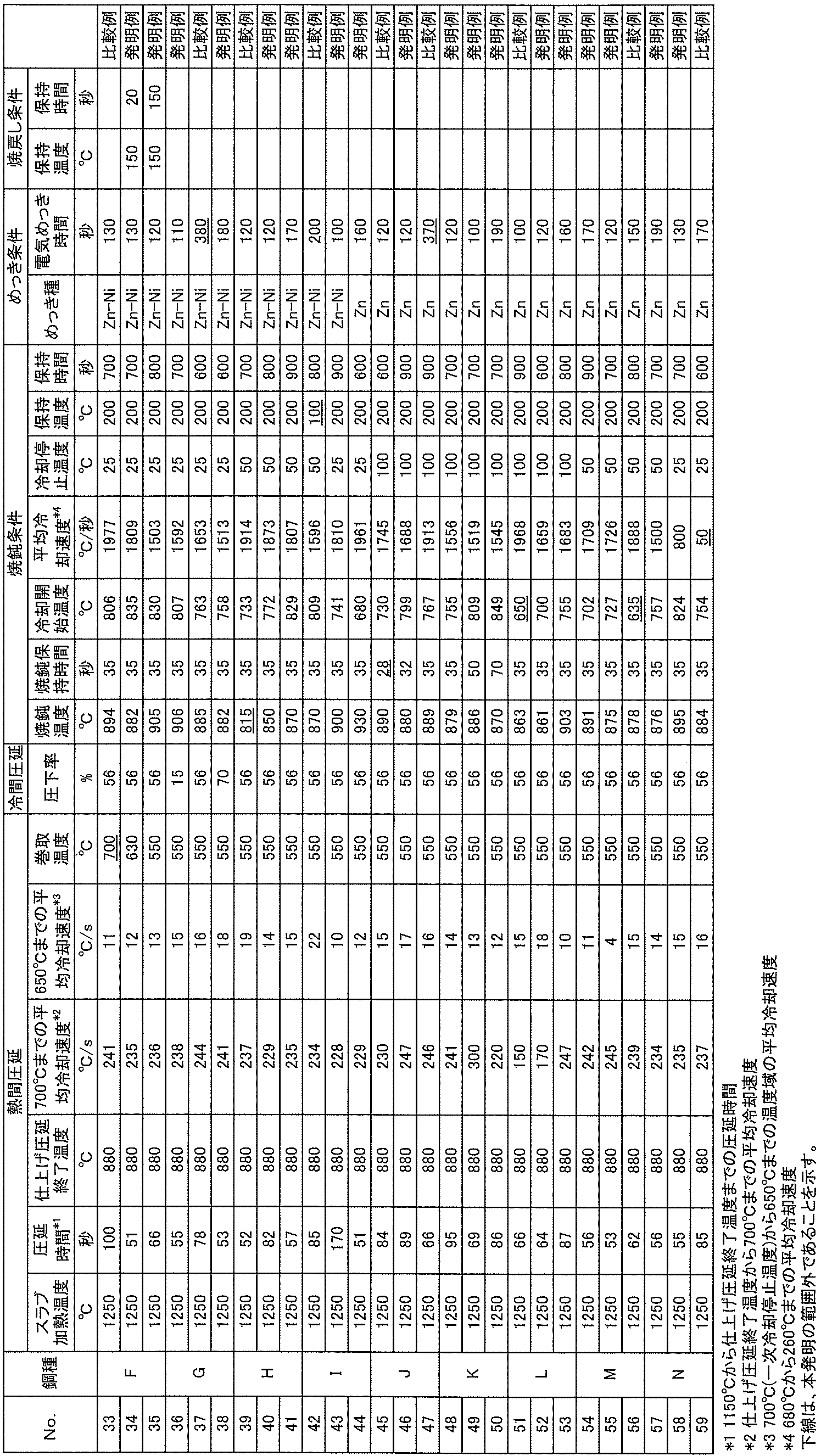
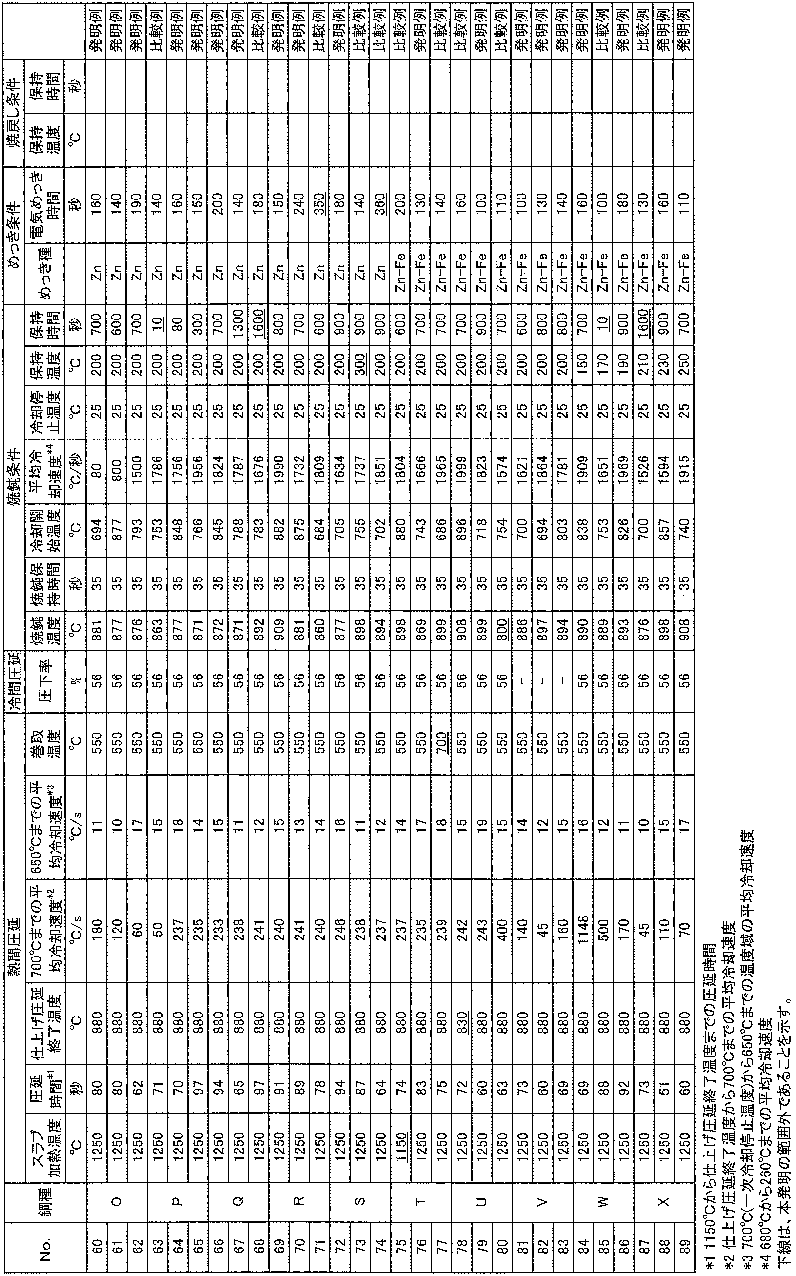
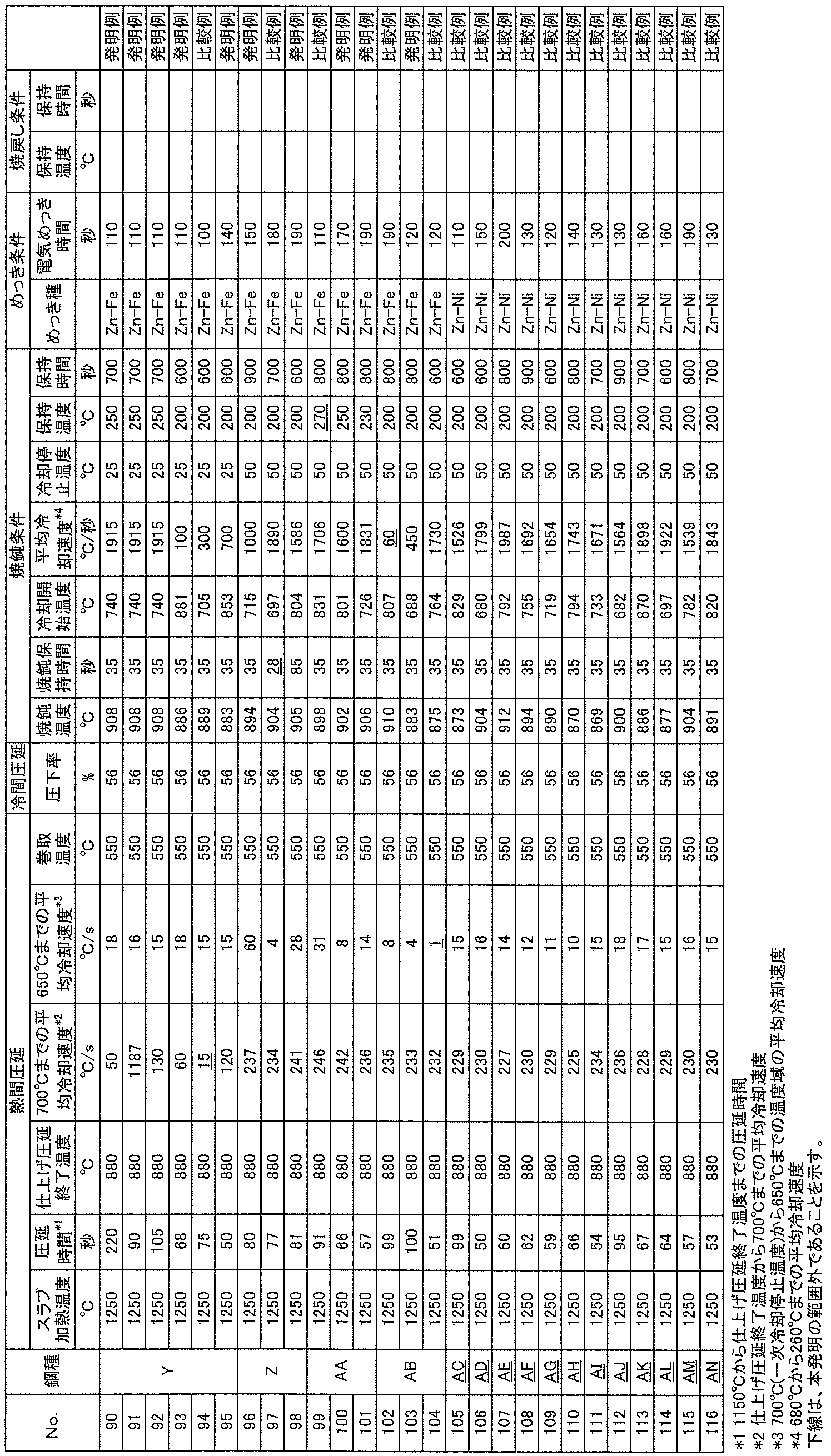
各種製造条件で得られた電気亜鉛系めっき鋼板に対して、鋼組織を解析することで組織分率を調査し、引張試験を実施することで引張強度等の引張特性を評価し、曲げ試験により曲げ性を評価した。各評価の方法は次のとおりである。
各電気亜鉛系めっき鋼板の圧延方向および圧延方向に対して垂直方向から試験片を採取し、圧延方向に平行な板厚L断面を鏡面研磨し、ナイタール液で組織現出した後、走査電子顕微鏡を用いて観察し、倍率1500倍のSEM像上の、実長さ82μm×57μmの領域上に4.8μm間隔の16×15の格子をおき、各相上にある点数を数えるポイントカウンティング法により、焼戻しマルテンサイト(表3-1~表3-4ではTMと表記)およびベイナイト(表3-1~表3-4ではBと表記)の面積率を調査した。組織全体における平均粒径が50nm以下の炭化物を有するベイナイトおよび平均粒径が50nm以下の炭化物を有する焼戻しマルテンサイトの面積率は、倍率1500倍で板厚全厚を連続的に観察し、そのSEM像から求めたそれぞれの面積率の平均値とした。素材鋼板の表面から板厚1/8までの領域における平均粒径が50nm以下の炭化物を有するベイナイト、平均粒径が50nm以下の炭化物を有する焼戻しマルテンサイトの面積率は、倍率1500倍で素材鋼板の表面から素材鋼板の板厚1/8までの領域を連続的に観察し、そのSEM像から求めたそれぞれの面積率の平均値とした。焼戻しマルテンサイトやベイナイトは白色の組織を呈しており、旧オーステナイト粒界内にブロックやパケットが現出した組織を呈しており、内部に微細な炭化物が析出している。また、ブロック粒の面方位とエッチングの程度によっては、内部の炭化物が現出しにくい場合もあるので、その場合はエッチングを十分に行い確認する必要がある。なお、焼戻しマルテンサイトおよびベイナイトに含まれる炭化物の平均粒径は、下記の方法により算出した。
各電気亜鉛系めっき鋼板の圧延方向および圧延方向に対して垂直方向から試験片を採取し、圧延方向に平行な板厚L断面を鏡面研磨し、ナイタール液で組織現出した後、走査電子顕微鏡を用いて素材鋼板の表面から板厚1/8まで連続的に観察し、倍率5000倍のSEM像1つから焼戻しマルテンサイトおよびベイナイトが含まれる旧オーステナイト粒の内部にある炭化物の個数を算出し、組織の二値化を行うことで1つの結晶粒の内部にある炭化物の合計面積を算出した。この炭化物の個数と合計面積より炭化物1個当たりの面積を算出し、素材鋼板の表面から板厚1/8までの領域における炭化物の平均粒径を算出した。組織全体における炭化物の平均粒径の測定方法は、走査電子顕微鏡を用いて素材鋼板の板厚1/4位置を観察し、以降は上記素材鋼板の表面から板厚1/8までの領域における炭化物の平均粒径を算出した方法と同様の方法で組織全体における炭化物の平均粒径を測定した。ここでは板厚1/4位置の組織が組織全体の平均的な組織であるとした。
各電気亜鉛系めっき鋼板の圧延方向および圧延方向に対して垂直方向から試験片を採取し、圧延方向に平行な板厚L断面を鏡面研磨し、組織現出のための腐食を行わずに、光学顕微鏡を用いて観察し、倍率400倍の光顕写真より黒く現出したものを介在物として測定した。また、各電気亜鉛系めっき鋼板の圧延方向および圧延方向に対して垂直方向から試験片を採取し、圧延方向に平行な板厚L断面を鏡面研磨し、ナイタール液で組織現出した後、走査電子顕微鏡を用いて観察し、倍率5000倍のSEM像より平均粒径が0.1μm以上の粗大炭化物を測定した。介在物もしくは粗大炭化物の長軸と短軸の長さを測定し、その平均値を平均粒径とした。また、前記平均粒径に円周率πを乗ずることで、介在物および平均粒径が0.1μm以上の炭化物各々の外周を算出し、その合計を、介在物および平均粒径が0.1μm以上の炭化物の外周の合計とした。
各電気亜鉛系めっき鋼板の圧延方向から、標点間距離50mm、標点間幅25mm、板厚1.4mmのJIS5号試験片を採取し、引張速度が10mm/分で引張試験を行い、引張強度(表3-1~表3-4でTSと表記)および降伏強度(表3-1~表3-4でYSと表記)、伸び(表3-1~表3-4でElと表記)を測定した。また、YS/TSから降伏比(表3-1~表3-4でYRと表記)を求めた。
各電気亜鉛系めっき鋼板の圧延方向に対して垂直方向から、長軸長さ100mm、短軸長さ30mmの短冊状の板を採取し、長さが100mmとなる長辺側の端面の切り出しはせん断加工とし、せん断加工ままの状態で(バリを除去する機械加工を施さずに)、バリが曲げ外周側となるように曲げ加工を施した。曲げ加工は、曲げ頂点内側の角度が90度(V曲げ)となるように行った。先端曲げ半径をRと鋼板の板厚をtとしたときに、R/tで評価をおこなった。
各電気亜鉛系めっき鋼板の幅中央部から、長軸長さ30mm、短軸長さ5mmの短冊状の板を採取した。この短冊の表面のめっきをハンディルーターで完全に除去し、昇温脱離分析装置を用いて、200℃/時間の昇温速度で水素分析した。また、短冊状の板を採取し、めっきを除去した後は、直ちに水素分析を実施した。そして、加熱開始温度(25℃)から200℃までに放出される累積水素量を測定し、これを鋼中の拡散性水素量とした。
上記評価結果を表3-1~表3-4に示す。
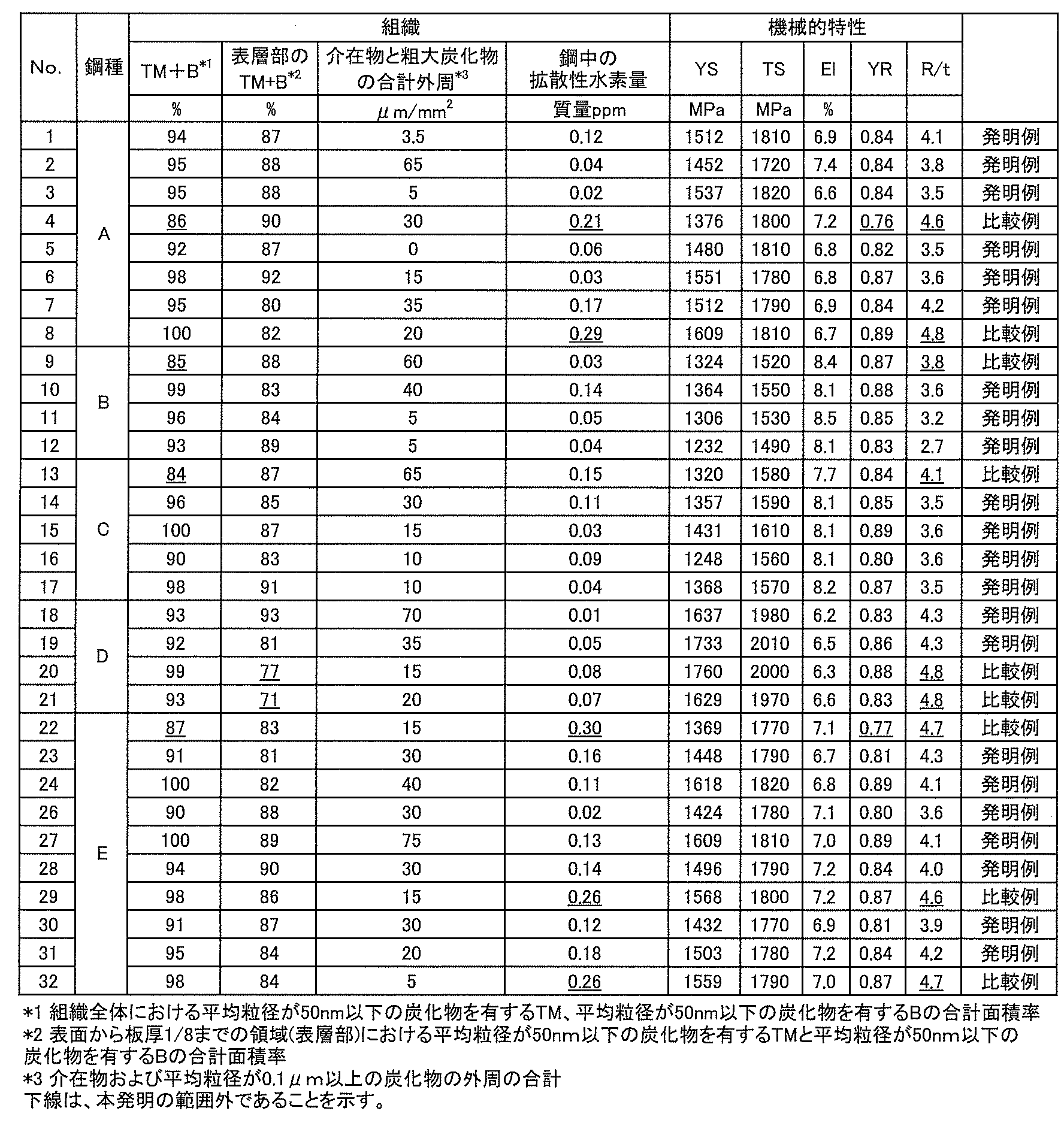
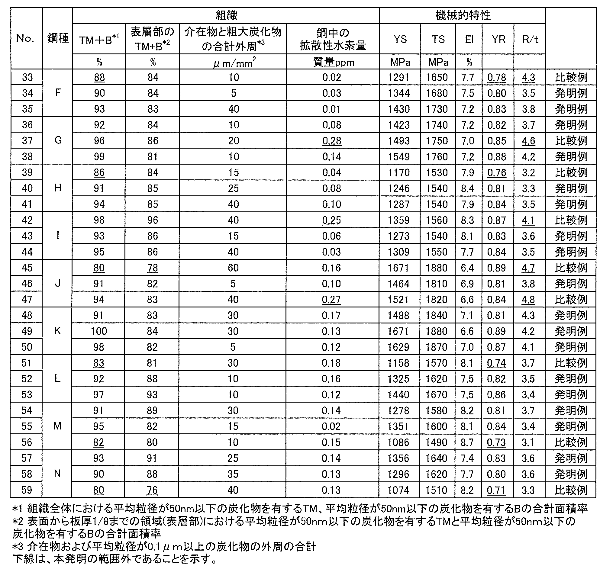
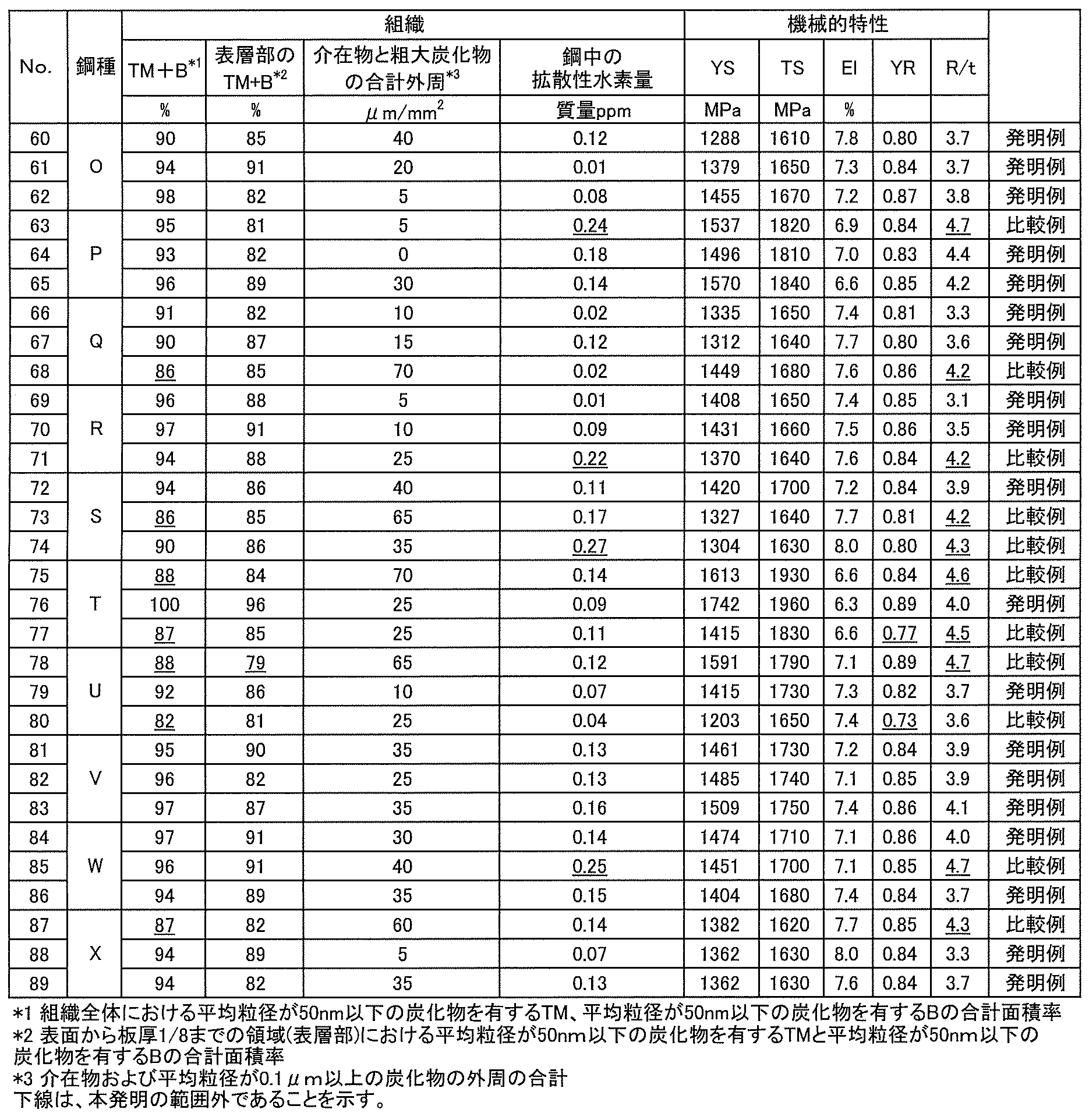

Claims (12)
- 素材鋼板の表面に、電気亜鉛系めっきを有する高降伏比高強度電気亜鉛系めっき鋼板であって、
前記素材鋼板は、質量%で、
C:0.14%以上0.40%以下、
Si:0.001%以上2.0%以下、
Mn:0.10%以上1.70%以下、
P:0.05%以下、
S:0.0050%以下、
Al:0.01%以上0.20%以下及び
N:0.010%以下を含有し、残部はFeおよび不可避的不純物からなる成分組成と、
鋼組織全体において、平均粒径が50nm以下の炭化物を有するベイナイト、平均粒径が50nm以下の炭化物を有する焼戻しマルテンサイトの1種または2種の面積率が合計で90%以上であり、素材鋼板の表面から板厚1/8までの領域において、平均粒径が50nm以下の炭化物を有するベイナイト、平均粒径が50nm以下の炭化物を有する焼戻しマルテンサイトの1種または2種の面積率が合計で80%以上である鋼組織とを有し、
鋼中の拡散性水素量が0.20質量ppm以下である、高降伏比高強度電気亜鉛系めっき鋼板。 - 前記素材鋼板は、前記成分組成と、前記鋼組織とを有し、
前記鋼組織が、介在物および平均粒径が0.1μm以上の炭化物を含み、前記介在物および平均粒径が0.1μm以上の炭化物の外周の合計が50μm/mm2以下である、請求項1に記載の高降伏比高強度電気亜鉛系めっき鋼板。 - 前記成分組成が、さらに、質量%で、
B:0.0002%以上0.0035%未満を含有する、請求項1または2に記載の高降伏比高強度電気亜鉛系めっき鋼板。 - 前記成分組成が、さらに、質量%で、
Nb:0.002%以上0.08%以下及び
Ti:0.002%以上0.12%以下のうちから選ばれる1種又は2種を含有する、請求項1~3のいずれかに記載の高降伏比高強度電気亜鉛系めっき鋼板。 - 前記成分組成が、さらに、質量%で、
Cu:0.005%以上1%以下及び
Ni:0.01%以上1%以下のうちから選ばれる1種又は2種を含有する、請求項1~4のいずれかに記載の高降伏比高強度電気亜鉛系めっき鋼板。 - 前記成分組成が、さらに、質量%で、
Cr:0.01%以上1.0%以下、
Mo:0.01%以上0.3%未満、
V:0.003%以上0.5%以下、
Zr:0.005%以上0.20%以下及び
W:0.005%以上0.20%以下のうちから選ばれる1種又は2種以上を含有する、請求項1~5のいずれかに記載の高降伏比高強度電気亜鉛系めっき鋼板。 - 前記成分組成が、さらに、質量%で、
Ca:0.0002%以上0.0030%以下、
Ce:0.0002%以上0.0030%以下、
La:0.0002%以上0.0030%以下及び
Mg:0.0002%以上0.0030%以下のうちから選ばれる1種又は2種以上を含有する、請求項1~6のいずれかに記載の高降伏比高強度電気亜鉛系めっき鋼板。 - 前記成分組成が、さらに、質量%で、
Sb:0.002%以上0.1%以下及び
Sn:0.002%以上0.1%以下のうちから選ばれる1種又は2種を含有する、請求項1~7のいずれかに記載の高降伏比高強度電気亜鉛系めっき鋼板。 - 請求項1~8のいずれかに記載の成分組成を有する鋼スラブを、スラブ加熱温度:1200℃以上、仕上げ圧延終了温度:840℃以上として熱間圧延を行った後、仕上げ圧延終了温度から700℃までの温度域を40℃/秒以上の平均冷却速度で700℃以下の一次冷却停止温度まで冷却し、その後、一次冷却停止温度から650℃までの温度域を2℃/秒以上の平均冷却速度で冷却し、630℃以下の巻取温度まで冷却して巻き取る熱延工程と、
前記熱延工程で得られた鋼板を、AC3点以上の焼鈍温度で30秒以上保持した後、冷却開始温度:680℃以上、680℃から260℃まで平均冷却速度:70℃/秒以上、冷却停止温度:260℃以下の条件で冷却し、150~260℃の温度域の保持温度で20~1500秒保持する焼鈍工程と、
前記焼鈍工程後の鋼板を室温まで冷却し、電気めっき時間:300秒以内の電気亜鉛系めっきを施す電気めっき工程とを有する、高降伏比高強度電気亜鉛系めっき鋼板の製造方法。 - さらに、熱延工程と焼鈍工程の間に、前記熱延工程後の鋼板を冷間圧延する冷延工程を有する、請求項9に記載の高降伏比高強度電気亜鉛系めっき鋼板の製造方法。
- さらに、電気めっき工程後の鋼板を250℃以下の温度域で以下の式(1)を満たす保持時間tで保持する焼戻し工程を有する、請求項9または10に記載の高降伏比高強度電気亜鉛系めっき鋼板の製造方法。
(T+273)(logt+4)≦2700 ・・・(1)
ただし、式(1)におけるTは、焼戻し工程における保持温度(℃)であり、tは焼戻し工程における保持時間(秒)である。 - 前記熱延工程における1150℃から仕上げ圧延終了温度までの圧延時間を200秒以内とする、請求項9~11のいずれかに記載の高降伏比高強度電気亜鉛系めっき鋼板の製造方法。
Priority Applications (6)
| Application Number | Priority Date | Filing Date | Title |
|---|---|---|---|
| KR1020217011162A KR102537350B1 (ko) | 2018-10-18 | 2019-08-06 | 고항복비 고강도 전기 아연계 도금 강판 및 그의 제조 방법 |
| JP2019562014A JP6760520B1 (ja) | 2018-10-18 | 2019-08-06 | 高降伏比高強度電気亜鉛系めっき鋼板及びその製造方法 |
| EP19873058.2A EP3828298B1 (en) | 2018-10-18 | 2019-08-06 | High yield ratio, high strength electro-galvanized steel sheet, and manufacturing method thereof |
| US17/284,933 US12043883B2 (en) | 2018-10-18 | 2019-08-06 | High-yield-ratio high-strength electrogalvanized steel sheet and method for manufacturing the same |
| CN201980068496.7A CN112930411B (zh) | 2018-10-18 | 2019-08-06 | 高屈服比高强度电镀锌系钢板及其制造方法 |
| MX2021004419A MX2021004419A (es) | 2018-10-18 | 2019-08-06 | Lamina de acero electrogalvanizada de alta resistencia y alto limite de alargamiento y metodo para la fabricacion de la misma. |
Applications Claiming Priority (2)
| Application Number | Priority Date | Filing Date | Title |
|---|---|---|---|
| JP2018196590 | 2018-10-18 | ||
| JP2018-196590 | 2018-10-18 |
Publications (1)
| Publication Number | Publication Date |
|---|---|
| WO2020079925A1 true WO2020079925A1 (ja) | 2020-04-23 |
Family
ID=70283945
Family Applications (1)
| Application Number | Title | Priority Date | Filing Date |
|---|---|---|---|
| PCT/JP2019/030792 Ceased WO2020079925A1 (ja) | 2018-10-18 | 2019-08-06 | 高降伏比高強度電気亜鉛系めっき鋼板及びその製造方法 |
Country Status (7)
| Country | Link |
|---|---|
| US (1) | US12043883B2 (ja) |
| EP (1) | EP3828298B1 (ja) |
| JP (1) | JP6760520B1 (ja) |
| KR (1) | KR102537350B1 (ja) |
| CN (1) | CN112930411B (ja) |
| MX (1) | MX2021004419A (ja) |
| WO (1) | WO2020079925A1 (ja) |
Cited By (7)
| Publication number | Priority date | Publication date | Assignee | Title |
|---|---|---|---|---|
| CN114058964A (zh) * | 2021-11-30 | 2022-02-18 | 宝武集团马钢轨交材料科技有限公司 | 一种高速车轴用钢及其热处理方法和生产方法 |
| WO2023074189A1 (ja) | 2021-10-27 | 2023-05-04 | 日本製鉄株式会社 | ホットスタンプ成形体 |
| KR20230109161A (ko) * | 2020-12-25 | 2023-07-19 | 제이에프이 스틸 가부시키가이샤 | 강판, 부재 및 그것들의 제조 방법 |
| JP2023139466A (ja) * | 2022-03-22 | 2023-10-04 | Jfeスチール株式会社 | 高強度鋼板及び自動車車体 |
| WO2023199638A1 (ja) | 2022-04-14 | 2023-10-19 | 日本製鉄株式会社 | ホットスタンプ成形体 |
| WO2023199635A1 (ja) | 2022-04-14 | 2023-10-19 | 日本製鉄株式会社 | ホットスタンプ成形体 |
| WO2026071091A1 (ja) * | 2024-09-30 | 2026-04-02 | Jfeスチール株式会社 | 鋼板、部材およびそれらの製造方法 |
Families Citing this family (8)
| Publication number | Priority date | Publication date | Assignee | Title |
|---|---|---|---|---|
| JP6950835B2 (ja) * | 2019-05-16 | 2021-10-13 | Jfeスチール株式会社 | 高強度部材、高強度部材の製造方法及び高強度部材用鋼板の製造方法 |
| KR102557845B1 (ko) * | 2021-05-28 | 2023-07-24 | 현대제철 주식회사 | 냉연 강판 및 그 제조 방법 |
| KR20220164330A (ko) * | 2021-06-04 | 2022-12-13 | 현대제철 주식회사 | 핫스탬핑용 강판 및 그 제조방법 |
| CN113462985B (zh) * | 2021-07-16 | 2022-07-19 | 鞍钢股份有限公司 | 免退火折弯性能优异的低成本高表面硬度工具钢 |
| KR102714163B1 (ko) * | 2022-03-07 | 2024-10-11 | 현대제철 주식회사 | 핫 스탬핑 부품 및 이의 제조 방법 |
| CN117004878B (zh) * | 2022-04-29 | 2026-02-24 | 宝山钢铁股份有限公司 | 一种抗拉强度在1450MPa以上的超高强度冷轧钢带及其制造方法 |
| KR102747791B1 (ko) * | 2022-05-31 | 2024-12-31 | 현대제철 주식회사 | 초고강도 냉연강판 및 그 제조방법 |
| KR20250167007A (ko) * | 2023-03-27 | 2025-11-28 | 타타 스틸 리미티드 | 고강도 냉연 소둔 강 및 그 제조 방법 |
Citations (8)
| Publication number | Priority date | Publication date | Assignee | Title |
|---|---|---|---|---|
| JPH07197183A (ja) | 1993-12-29 | 1995-08-01 | Kobe Steel Ltd | 水素脆化の発生しない超高強度薄鋼板及び製造方法 |
| JP2010090475A (ja) | 2008-09-10 | 2010-04-22 | Jfe Steel Corp | 高強度鋼板およびその製造方法 |
| JP2011246746A (ja) | 2010-05-24 | 2011-12-08 | Kobe Steel Ltd | 曲げ加工性に優れた高強度冷延鋼板 |
| WO2012161241A1 (ja) * | 2011-05-25 | 2012-11-29 | 新日鐵住金株式会社 | 冷延鋼板及びその製造方法 |
| WO2017164346A1 (ja) * | 2016-03-25 | 2017-09-28 | 新日鐵住金株式会社 | 高強度鋼板および高強度亜鉛めっき鋼板 |
| WO2018062381A1 (ja) * | 2016-09-28 | 2018-04-05 | Jfeスチール株式会社 | 鋼板およびその製造方法 |
| WO2018123356A1 (ja) * | 2016-12-28 | 2018-07-05 | 株式会社神戸製鋼所 | 高強度鋼板および高強度電気亜鉛めっき鋼板 |
| WO2018124157A1 (ja) * | 2016-12-27 | 2018-07-05 | Jfeスチール株式会社 | 高強度亜鉛めっき鋼板及びその製造方法 |
Family Cites Families (8)
| Publication number | Priority date | Publication date | Assignee | Title |
|---|---|---|---|---|
| JP3993703B2 (ja) | 1998-09-03 | 2007-10-17 | 新日本製鐵株式会社 | 加工用薄鋼板の製造方法 |
| JP5412182B2 (ja) * | 2009-05-29 | 2014-02-12 | 株式会社神戸製鋼所 | 耐水素脆化特性に優れた高強度鋼板 |
| WO2011118126A1 (ja) * | 2010-03-24 | 2011-09-29 | Jfeスチール株式会社 | 超高強度部材の製造方法および使用方法 |
| JP5531757B2 (ja) * | 2010-04-28 | 2014-06-25 | 新日鐵住金株式会社 | 高強度鋼板 |
| MX2017001526A (es) | 2014-08-07 | 2017-05-11 | Jfe Steel Corp | Lamina de acero de alta resistencia y metodo para fabricar la misma. |
| KR101657796B1 (ko) | 2014-12-15 | 2016-09-20 | 주식회사 포스코 | 내지연파괴 특성이 우수한 고강도 강판 및 이의 제조방법 |
| KR102226643B1 (ko) | 2016-09-28 | 2021-03-10 | 제이에프이 스틸 가부시키가이샤 | 강판 및 그 제조 방법 |
| MX2019009513A (es) * | 2017-02-10 | 2019-11-05 | Jfe Steel Corp | Lamina de acero galvanizada de alta resistencia y metodo para producir la misma. |
-
2019
- 2019-08-06 CN CN201980068496.7A patent/CN112930411B/zh active Active
- 2019-08-06 WO PCT/JP2019/030792 patent/WO2020079925A1/ja not_active Ceased
- 2019-08-06 US US17/284,933 patent/US12043883B2/en active Active
- 2019-08-06 MX MX2021004419A patent/MX2021004419A/es unknown
- 2019-08-06 JP JP2019562014A patent/JP6760520B1/ja active Active
- 2019-08-06 EP EP19873058.2A patent/EP3828298B1/en active Active
- 2019-08-06 KR KR1020217011162A patent/KR102537350B1/ko active Active
Patent Citations (8)
| Publication number | Priority date | Publication date | Assignee | Title |
|---|---|---|---|---|
| JPH07197183A (ja) | 1993-12-29 | 1995-08-01 | Kobe Steel Ltd | 水素脆化の発生しない超高強度薄鋼板及び製造方法 |
| JP2010090475A (ja) | 2008-09-10 | 2010-04-22 | Jfe Steel Corp | 高強度鋼板およびその製造方法 |
| JP2011246746A (ja) | 2010-05-24 | 2011-12-08 | Kobe Steel Ltd | 曲げ加工性に優れた高強度冷延鋼板 |
| WO2012161241A1 (ja) * | 2011-05-25 | 2012-11-29 | 新日鐵住金株式会社 | 冷延鋼板及びその製造方法 |
| WO2017164346A1 (ja) * | 2016-03-25 | 2017-09-28 | 新日鐵住金株式会社 | 高強度鋼板および高強度亜鉛めっき鋼板 |
| WO2018062381A1 (ja) * | 2016-09-28 | 2018-04-05 | Jfeスチール株式会社 | 鋼板およびその製造方法 |
| WO2018124157A1 (ja) * | 2016-12-27 | 2018-07-05 | Jfeスチール株式会社 | 高強度亜鉛めっき鋼板及びその製造方法 |
| WO2018123356A1 (ja) * | 2016-12-28 | 2018-07-05 | 株式会社神戸製鋼所 | 高強度鋼板および高強度電気亜鉛めっき鋼板 |
Non-Patent Citations (1)
| Title |
|---|
| See also references of EP3828298A4 |
Cited By (15)
| Publication number | Priority date | Publication date | Assignee | Title |
|---|---|---|---|---|
| KR20230109161A (ko) * | 2020-12-25 | 2023-07-19 | 제이에프이 스틸 가부시키가이샤 | 강판, 부재 및 그것들의 제조 방법 |
| EP4242336A4 (en) * | 2020-12-25 | 2023-10-18 | JFE Steel Corporation | STEEL SHEET, ELEMENT, METHOD FOR PRODUCING THE STEEL SHEET AND METHOD FOR PRODUCING SAID ELEMENT |
| US12644169B2 (en) | 2020-12-25 | 2026-06-02 | Jfe Steel Corporation | Steel sheet, member, and methods for manufacturing the same |
| KR102865563B1 (ko) | 2020-12-25 | 2025-09-29 | 제이에프이 스틸 가부시키가이샤 | 강판, 부재 및 그것들의 제조 방법 |
| WO2023074189A1 (ja) | 2021-10-27 | 2023-05-04 | 日本製鉄株式会社 | ホットスタンプ成形体 |
| US12692585B2 (en) | 2021-10-27 | 2026-07-28 | Nippon Steel Corporation | Hot-stamp formed body |
| KR20240021876A (ko) | 2021-10-27 | 2024-02-19 | 닛폰세이테츠 가부시키가이샤 | 핫 스탬프 성형체 |
| CN114058964A (zh) * | 2021-11-30 | 2022-02-18 | 宝武集团马钢轨交材料科技有限公司 | 一种高速车轴用钢及其热处理方法和生产方法 |
| JP7605164B2 (ja) | 2022-03-22 | 2024-12-24 | Jfeスチール株式会社 | 高強度鋼板及び自動車車体 |
| JP2023139466A (ja) * | 2022-03-22 | 2023-10-04 | Jfeスチール株式会社 | 高強度鋼板及び自動車車体 |
| WO2023199635A1 (ja) | 2022-04-14 | 2023-10-19 | 日本製鉄株式会社 | ホットスタンプ成形体 |
| KR20240132338A (ko) | 2022-04-14 | 2024-09-03 | 닛폰세이테츠 가부시키가이샤 | 핫 스탬프 성형체 |
| KR20240130760A (ko) | 2022-04-14 | 2024-08-29 | 닛폰세이테츠 가부시키가이샤 | 핫 스탬프 성형체 |
| WO2023199638A1 (ja) | 2022-04-14 | 2023-10-19 | 日本製鉄株式会社 | ホットスタンプ成形体 |
| WO2026071091A1 (ja) * | 2024-09-30 | 2026-04-02 | Jfeスチール株式会社 | 鋼板、部材およびそれらの製造方法 |
Also Published As
| Publication number | Publication date |
|---|---|
| EP3828298A4 (en) | 2021-06-02 |
| MX2021004419A (es) | 2021-07-06 |
| KR102537350B1 (ko) | 2023-05-30 |
| EP3828298B1 (en) | 2024-07-10 |
| CN112930411B (zh) | 2022-08-30 |
| US12043883B2 (en) | 2024-07-23 |
| CN112930411A (zh) | 2021-06-08 |
| KR20210060550A (ko) | 2021-05-26 |
| JPWO2020079925A1 (ja) | 2021-02-15 |
| EP3828298A1 (en) | 2021-06-02 |
| JP6760520B1 (ja) | 2020-09-23 |
| US20210381085A1 (en) | 2021-12-09 |
Similar Documents
| Publication | Publication Date | Title |
|---|---|---|
| JP6760520B1 (ja) | 高降伏比高強度電気亜鉛系めっき鋼板及びその製造方法 | |
| EP3309273B1 (en) | Galvannealed steel sheet and method for manufacturing same | |
| JP6323617B1 (ja) | 高強度亜鉛めっき鋼板及びその製造方法 | |
| JP6787535B1 (ja) | 高強度鋼板およびその製造方法 | |
| CN113840934B (zh) | 高强度构件、高强度构件的制造方法和高强度构件用钢板的制造方法 | |
| CN104105807B (zh) | 高强度冷轧钢板及其制造方法 | |
| KR102541248B1 (ko) | 고연성 고강도 전기 아연계 도금 강판 및 그의 제조 방법 | |
| JP2017048412A (ja) | 溶融亜鉛めっき鋼板、合金化溶融亜鉛めっき鋼板、およびそれらの製造方法 | |
| JPWO2019106895A1 (ja) | 高強度亜鉛めっき鋼板およびその製造方法 | |
| WO2017164346A1 (ja) | 高強度鋼板および高強度亜鉛めっき鋼板 | |
| CN114645219A (zh) | 高强度镀锌钢板及其制造方法 | |
| CN108603262B (zh) | 高屈服比型高强度镀锌钢板及其制造方法 | |
| CN114555845B (zh) | 高强度钢板及其制造方法 | |
| WO2020129402A1 (ja) | 鋼板、部材およびこれらの製造方法 | |
| WO2016147549A1 (ja) | 高強度冷延鋼板およびその製造方法 | |
| JP7541652B1 (ja) | 亜鉛めっき鋼板および部材、ならびに、それらの製造方法 | |
| WO2020090302A1 (ja) | 高強度部材、高強度部材の製造方法及び高強度部材用鋼板の製造方法 | |
| WO2020203943A1 (ja) | 亜鉛めっき鋼板およびその製造方法 | |
| WO2020129403A1 (ja) | 鋼板、部材およびこれらの製造方法 | |
| JP5637530B2 (ja) | 高延性で、化成処理性に優れる780MPa以上の引張強度を有する超高強度冷延鋼板 | |
| JP2011241430A (ja) | 高強度溶融亜鉛めっき鋼板およびその製造方法 | |
| JP2007009269A (ja) | 高延性で、化成処理性に優れる780MPa以上の引張強度を有する超高強度冷延鋼板およびその製造方法 | |
| JP7708344B1 (ja) | 亜鉛めっき鋼板および部材、ならびに、それらの製造方法 | |
| CN113544301B (zh) | 钢板 | |
| JP2012167320A (ja) | 合金化溶融亜鉛めっき鋼板およびその製造方法 |
Legal Events
| Date | Code | Title | Description |
|---|---|---|---|
| ENP | Entry into the national phase |
Ref document number: 2019562014 Country of ref document: JP Kind code of ref document: A |
|
| 121 | Ep: the epo has been informed by wipo that ep was designated in this application |
Ref document number: 19873058 Country of ref document: EP Kind code of ref document: A1 |
|
| ENP | Entry into the national phase |
Ref document number: 2019873058 Country of ref document: EP Effective date: 20210225 |
|
| ENP | Entry into the national phase |
Ref document number: 20217011162 Country of ref document: KR Kind code of ref document: A |
|
| WWE | Wipo information: entry into national phase |
Ref document number: 2101002157 Country of ref document: TH Ref document number: MX/A/2021/004419 Country of ref document: MX |
|
| NENP | Non-entry into the national phase |
Ref country code: DE |
|
| WWG | Wipo information: grant in national office |
Ref document number: MX/A/2021/004419 Country of ref document: MX |