WO2020071499A1 - フォーカス位置評価装置、方法、及びプログラム - Google Patents
フォーカス位置評価装置、方法、及びプログラムInfo
- Publication number
- WO2020071499A1 WO2020071499A1 PCT/JP2019/039175 JP2019039175W WO2020071499A1 WO 2020071499 A1 WO2020071499 A1 WO 2020071499A1 JP 2019039175 W JP2019039175 W JP 2019039175W WO 2020071499 A1 WO2020071499 A1 WO 2020071499A1
- Authority
- WO
- WIPO (PCT)
- Prior art keywords
- focus position
- image
- scanning direction
- subject
- photographing
- Prior art date
- Legal status (The legal status is an assumption and is not a legal conclusion. Google has not performed a legal analysis and makes no representation as to the accuracy of the status listed.)
- Ceased
Links
Images







Classifications
-
- G—PHYSICS
- G02—OPTICS
- G02B—OPTICAL ELEMENTS, SYSTEMS OR APPARATUS
- G02B21/00—Microscopes
-
- G—PHYSICS
- G02—OPTICS
- G02B—OPTICAL ELEMENTS, SYSTEMS OR APPARATUS
- G02B21/00—Microscopes
- G02B21/24—Base structure
-
- G—PHYSICS
- G02—OPTICS
- G02B—OPTICAL ELEMENTS, SYSTEMS OR APPARATUS
- G02B21/00—Microscopes
- G02B21/36—Microscopes arranged for photographic purposes or projection purposes or digital imaging or video purposes including associated control and data processing arrangements
-
- G—PHYSICS
- G02—OPTICS
- G02B—OPTICAL ELEMENTS, SYSTEMS OR APPARATUS
- G02B7/00—Mountings, adjusting means, or light-tight connections, for optical elements
- G02B7/02—Mountings, adjusting means, or light-tight connections, for optical elements for lenses
- G02B7/04—Mountings, adjusting means, or light-tight connections, for optical elements for lenses with mechanism for focusing or varying magnification
-
- G—PHYSICS
- G02—OPTICS
- G02B—OPTICAL ELEMENTS, SYSTEMS OR APPARATUS
- G02B7/00—Mountings, adjusting means, or light-tight connections, for optical elements
- G02B7/28—Systems for automatic generation of focusing signals
-
- G—PHYSICS
- G02—OPTICS
- G02B—OPTICAL ELEMENTS, SYSTEMS OR APPARATUS
- G02B7/00—Mountings, adjusting means, or light-tight connections, for optical elements
- G02B7/28—Systems for automatic generation of focusing signals
- G02B7/36—Systems for automatic generation of focusing signals using image sharpness techniques, e.g. image processing techniques for generating autofocus signals
-
- G—PHYSICS
- G03—PHOTOGRAPHY; CINEMATOGRAPHY; ANALOGOUS TECHNIQUES USING WAVES OTHER THAN OPTICAL WAVES; ELECTROGRAPHY; HOLOGRAPHY
- G03B—APPARATUS OR ARRANGEMENTS FOR TAKING PHOTOGRAPHS OR FOR PROJECTING OR VIEWING THEM; APPARATUS OR ARRANGEMENTS EMPLOYING ANALOGOUS TECHNIQUES USING WAVES OTHER THAN OPTICAL WAVES; ACCESSORIES THEREFOR
- G03B13/00—Viewfinders; Focusing aids for cameras; Means for focusing for cameras; Autofocus systems for cameras
- G03B13/32—Means for focusing
- G03B13/34—Power focusing
- G03B13/36—Autofocus systems
-
- H—ELECTRICITY
- H04—ELECTRIC COMMUNICATION TECHNIQUE
- H04N—PICTORIAL COMMUNICATION, e.g. TELEVISION
- H04N23/00—Cameras or camera modules comprising electronic image sensors; Control thereof
- H04N23/60—Control of cameras or camera modules
Definitions
- the technology of the present disclosure relates to a focus position evaluation device, a method, and a program.
- pluripotent stem cells such as ES (Embryonic Stem) cells and iPS (Induced Pluripotent Stem) cells and cells induced to differentiate are photographed with a microscope or the like, and the characteristics of the images are captured to determine the differentiation state of the cells.
- Pluripotent stem cells such as ES cells and iPS cells have the ability to differentiate into cells of various tissues, and are attracting attention as cells that can be applied in regenerative medicine, drug development, disease elucidation, etc. I have.
- Patent Document 1 a sample to be photographed is fixed by a translucent member having a mark that gives at least one of a phase change and an amplitude change to transmitted light, and the image of the sample and the image of the mark are fixed.
- a method has been proposed in which a mixed captured image is acquired, and a focus position is evaluated based on an evaluation value calculated for the captured image and an evaluation value calculated for a reference image that does not include an image of a sample acquired in advance. .
- Patent Document 2 discloses that, for example, in an autofocus apparatus using a phase difference optical system, when the defocus amount becomes too large, a locality for specifying a phase difference (parallax) obtained from a set of phase difference images is disclosed. It is described that since the region deviates from the phase contrast image, the observation surface in the phase contrast image needs to be within the detectable range of the defocus amount.
- a reference image hereinafter, also referred to as a comparative image
- a method for evaluating a focus position by making an inquiry is disclosed.
- fine beads having a sphere as a marker.
- the fine beads when the fine beads are stationary at the time of photographing, the fine beads have a circular shape in the photographed image, but when performing the tiling photographing, at least one of the container containing the fine beads and the photographing optical system. Moving the microbeads during shooting, the light image at the focal point of the fine bead image flows, and in the captured image obtained, the fine beads are not circular but a circular image is trailed. The resulting image will be.
- the focus position is evaluated by comparing the photographed image acquired by tiling photographing with the comparison image. There is a possibility that the accuracy of the evaluation will be reduced.
- the present disclosure has been made in view of the above circumstances, and has as its object to improve the accuracy of focus position evaluation.
- the focus position evaluation device of the present disclosure moves a stage in which a container housing a subject is installed and an imaging optical system that forms an image of the subject in the container in a scanning direction by moving at least one of the stage and the container.
- a focus position evaluation device that scans an observation area and evaluates a focus position of an imaging device that photographs each observation area
- a comparison image acquisition unit that scans the observation region in at least one scanning direction with respect to the container, and acquires a plurality of comparison images to be compared with the focus position evaluation by photographing the subject at each of different focus positions by the imaging device; , By scanning the observation area for the container, by observing the observation image obtained by photographing the subject by the photographing device, by comparing the comparison image in the scanning direction corresponding to the scanning direction when photographing the subject,
- An evaluation unit for evaluating a focus position including.
- the comparative image acquiring unit acquires a plurality of comparative images by photographing the subject in at least one of the one scanning direction and the scanning direction opposite to the one scanning direction. Can be.
- the comparison image acquisition unit acquires a plurality of comparison images in one scanning direction by photographing a subject in one scanning direction, and compares the acquired plurality of comparison images in one scanning direction. By inverting each pixel position of the image, a plurality of comparison images in a scanning direction opposite to one scanning direction can be obtained.
- Another focus position evaluation apparatus of the present disclosure is to move at least one of a stage on which a container housing a subject is installed and an imaging optical system for forming an image of the subject in the container in the scanning direction to move the container.
- a focus position evaluation device that scans an observation area with respect to and evaluates a focus position of an imaging device that photographs each observation area, In an observation area, an image acquisition unit that acquires a plurality of photographed images by photographing a subject at different focus positions, A comparison image acquisition unit configured to generate a comparison image to be compared with the focus position evaluation for each scanning direction based on the plurality of captured images, and to acquire a plurality of the generated comparison images;
- An evaluation unit that evaluates a focus position by collating an observation image acquired by photographing the subject with the photographing device and a comparison image in a scanning direction corresponding to the scanning direction when photographing the subject; including.
- a plurality of comparison images may be acquired at different scanning speeds.
- the subject may be a marker.
- the marker may include a fine structure of cells, and in the above-described focus position evaluation device of the present disclosure, the marker is a fine bead. Is also good.
- the subject may be a cell.
- the imaging device may be a microscope device.
- the focus position evaluation method of the present disclosure is to move at least one of a stage in which a container housing a subject is placed and an imaging optical system that forms an image of the subject in the container in the scanning direction, with respect to the container.
- a focus position evaluation method for evaluating a focus position of an image capturing apparatus that scans an observation area and shoots each observation area, Scanning the observation area in at least one scanning direction with respect to the container, and acquiring a plurality of comparison images to be compared with the focus position evaluation by photographing the subject at each different focus position by the imaging device, By scanning the observation area for the container, by observing the observation image obtained by photographing the subject by the photographing device, by comparing the comparison image in the scanning direction corresponding to the scanning direction when photographing the subject, Evaluate the focus position.
- the comparison image acquisition unit may create a comparison image having features based on the scanning direction from the captured image.
- At least one of a stage on which a container housing a subject is installed and an imaging optical system that forms an image of the subject in the container is moved in a scanning direction.
- a focus position evaluation method for scanning an observation area with respect to the container, and evaluating a focus position of an imaging device that photographs each observation area In the observation area, a plurality of photographed images are obtained by photographing a subject at different focus positions, Based on the plurality of captured images, generate a comparison image to be compared with the focus position evaluation for each scanning direction, obtain a plurality of generated comparison images, The focus position is evaluated by comparing an observation image acquired by photographing the subject with the photographing device and a comparison image in the scanning direction corresponding to the scanning direction when photographing the subject.
- the focus position evaluation method according to the present disclosure may be provided as a program for causing a computer to execute the method.
- Another focus position evaluation apparatus is to move at least one of a stage on which a container housing a subject is installed and an imaging optical system for forming an image of the subject in the container in the scanning direction to move the container.
- a focus position evaluation device that scans an observation area for, and evaluates a focus position of an imaging device that images each observation area, and a memory that stores an instruction to be executed by a computer,
- a processor configured to execute the stored instructions, the processor comprising: Scanning the observation area in at least one scanning direction with respect to the container, and acquiring a plurality of comparison images to be compared with the focus position evaluation by photographing the subject at each different focus position by the imaging device, Focusing is performed by scanning the observation area with respect to the container and comparing an observation image acquired by photographing the subject with the photographing device and a comparative image in the scanning direction corresponding to the scanning direction when photographing the subject. Execute the process of evaluating the position.
- Still another focus position evaluation apparatus moves at least one of a stage on which a container housing a subject is installed and an imaging optical system for forming an image of the subject in the container in a scanning direction.
- a focus position evaluation device that scans the observation area with respect to the container and evaluates a focus position of an imaging device that images each observation area, and a memory that stores an instruction to be executed by a computer,
- a processor configured to execute the stored instructions, the processor comprising: Obtain a plurality of captured images by capturing the subject at different focus positions for the observation area, Based on the plurality of captured images, generate a comparison image to be compared with the focus position evaluation for each scanning direction, obtain a plurality of generated comparison images, A process of evaluating a focus position is performed by comparing an observation image acquired by photographing the subject with the photographing device and the comparison image in the scanning direction corresponding to the scanning direction in photographing the subject.
- FIG. 1 is a schematic diagram illustrating a schematic configuration of a microscope device in a microscope imaging system to which a focus position evaluation device according to a first embodiment of the present disclosure is applied.
- Schematic diagram showing the configuration of the imaging optical system Perspective view showing the configuration of the stage
- Schematic diagram showing the configuration of the focal length changing optical system 1 is a block diagram illustrating a schematic configuration of a microscope observation system to which a focus position evaluation device according to a first embodiment of the present disclosure is applied.
- FIG. 4 is a view for explaining image capturing of a marker for acquiring a teacher marker image used for learning of a classifier.
- Diagram showing an example of a teacher marker image Diagram showing teacher marker images with different scanning directions FIG.
- FIG. 9 shows the teacher marker image of FIG. 9 with enhanced contrast.
- Profile of center height in teacher's marker image when scanned from right to left Profile of center height in teacher's marker image when scanned from left to right
- FIG. 7 is a diagram showing a result of determining a focus position
- Flowchart showing processing performed in a comparison image acquisition unit 4 is a flowchart illustrating processing performed in the first embodiment.
- FIG. 4 is a block diagram illustrating a schematic configuration of a microscope observation system to which a focus position evaluation device according to a third embodiment of the present disclosure is applied.
- FIG. 1 is a schematic diagram illustrating a schematic configuration of a microscope device in a microscope imaging system to which the focus position evaluation device according to the first embodiment of the present disclosure is applied.
- the microscope device 10 captures a phase difference image of a cultured cell to be observed.
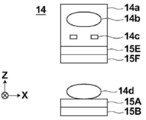
- the microscope apparatus 10 includes a white light source 11 that emits white light, a condenser lens 12, a slit plate 13, an imaging optical system 14, an operation unit 15, and an imaging unit 16.
- the microscope device 10 includes a focal length changing optical system 70.
- the operation unit 15 includes a first operation unit 15A, a second operation unit 15B, a third operation unit 15C, a fourth operation unit 15D, a fifth operation unit 15E, a sixth operation unit 15F, and a seventh operation unit.
- An operation unit 15G is provided. The operations of the first to seventh operation units 15A to 15G will be described later.
- the slit plate 13 is provided with a ring-shaped slit that transmits white light with respect to a light-shielding plate that shields white light emitted from the white light source 11, and the white light passes through the slit to form a ring. Illumination light L is formed.
- the imaging optical system 14 forms a phase difference image for each observation region obtained by dividing the range of the culture container 50 on the imaging unit 16.
- FIG. 2 is a diagram illustrating a detailed configuration of the imaging optical system 14.
- the imaging optical system 14 includes a phase difference lens 14a and an imaging lens 14d.
- the phase difference lens 14a includes an objective lens 14b and a phase plate 14c.
- the phase plate 14c is formed by forming a phase ring on a transparent plate transparent to the wavelength of the illumination light L.
- the size of the slit of the slit plate 13 is conjugate with the phase ring of the phase plate 14c.
- the phase ring is formed by forming a phase film that shifts the phase of incident light by ⁇ wavelength and a neutral density filter that diminishes incident light in a ring shape.
- Direct light incident on the phase ring has a phase shifted by ⁇ wavelength and its brightness is weakened by passing through the phase ring.
- most of the diffracted light diffracted by the observation target passes through the transparent plate of the phase plate 14c, and its phase and brightness do not change.
- the phase difference lens 14a having the objective lens 14b is moved in the optical axis direction of the objective lens 14b by the fifth operation unit 15E of the operation unit 15 shown in FIG.
- the optical axis direction of the objective lens 14b and the Z direction are the same direction.
- the autofocus control is performed by moving the objective lens 14b in the Z direction, and the contrast of the phase difference image acquired by the imaging unit 16 is adjusted.
- the magnification of the phase difference lens 14a may be changed.
- the phase difference lens 14a or the imaging optical system 14 having different magnifications may be configured to be exchangeable.
- the replacement of the phase difference lens 14a or the imaging optical system 14 may be performed automatically or manually by a user.
- the objective lens 14b is a liquid lens whose focal length can be changed.
- the lens is not limited to the liquid lens, and an arbitrary lens such as a liquid crystal lens and a shape deformable lens can be used.
- the applied voltage is changed by the sixth operating unit 15F in the operating unit 15 shown in FIG. 1, and the focal length is changed. Thereby, the focal length of the imaging optical system 14 is changed.
- Autofocus control is also performed by changing the focal length of the objective lens 14b, and the contrast of the phase difference image acquired by the imaging unit 16 is adjusted.
- the phase difference image having passed through the phase difference lens 14a enters the imaging lens 14d, and forms an image on the imaging unit 16.
- the imaging lens 14d is a liquid lens whose focal length can be changed.
- the lens is not limited to the liquid lens, and an arbitrary lens such as a liquid crystal lens and a shape deformable lens can be used.
- the applied voltage is changed by the first operating unit 15A in the operating unit 15 shown in FIG. 1, and the focal length is changed. Thereby, the focal length of the imaging optical system 14 is changed.
- the autofocus control is performed by changing the focal length of the imaging lens 14d, and the contrast of the phase difference image acquired by the imaging unit 16 is adjusted.
- the imaging lens 14d is moved in the optical axis direction of the imaging lens 14d by the second operation unit 15B in the operation unit 15 shown in FIG.
- the optical axis direction of the imaging lens 14d and the Z direction are the same direction.
- the autofocus control is performed by moving the imaging lens 14d in the Z direction, and the contrast of the phase difference image acquired by the imaging unit 16 is adjusted.
- the imaging unit 16 acquires the phase difference image formed by the imaging lens 14d.
- the imaging unit 16 includes an image sensor such as a charge-coupled device (CCD) image sensor or a complementary metal-oxide semiconductor (CMOS) image sensor.
- CMOS complementary metal-oxide semiconductor
- an image sensor provided with an RGB (Red Green Blue) color filter may be used, or a monochrome image sensor may be used.
- the imaging unit 16 is moved in the Z direction by a third operation unit 15C in the operation unit 15 shown in FIG.
- the direction perpendicular to the imaging surface of the imaging unit 16 and the Z direction are the same direction.
- the autofocus control is performed by moving the imaging unit 16 in the Z direction, and the contrast of the phase difference image acquired by the imaging unit 16 is adjusted.
- a stage 51 is provided between the slit plate 13 and the imaging optical system 14. On the stage 51, a culture container 50 that accommodates cells to be observed is installed.
- the culture container 50 may have any form as long as it can accommodate the observation target.
- a container having a form having a bottom and a continuous wall at the bottom such as a petri dish, a dish, a flask or a well plate, can be used as the container.
- a microchannel device or the like in which a fine channel is formed in a plate-like member can be used as a container.
- a plate-shaped material such as a slide glass can be used as the container.
- the cells contained in the culture container 50 include pluripotent stem cells such as iPS cells and ES cells, nerves differentiated from stem cells, skin, cardiac muscle and liver cells, and skin, retina, There are cells of the heart muscle, blood cells, nerves and organs.
- the stage 51 is moved in an X direction and a Y direction orthogonal to each other by a horizontal driving unit 17 (see FIG. 5) described later.
- the X direction and the Y direction are directions orthogonal to the Z direction, and directions orthogonal to each other in a horizontal plane.
- the X direction is the main scanning direction
- the Y direction is the sub scanning direction.
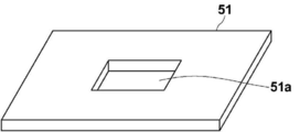
- FIG. 3 is a diagram illustrating an example of the stage 51. At the center of the stage 51, a rectangular opening 51a is formed. The culture vessel 50 is set on the member forming the opening 51a, and the phase difference image of the cells in the culture vessel 50 passes through the opening 51a.
- the stage 51 is moved in the Z direction by the fourth operating unit 15D, whereby the culture vessel 50 is moved in the Z direction.
- the fourth operation unit 15D includes an actuator such as a piezoelectric element, for example.
- the direction perpendicular to the surface of the stage 51 on which the culture vessel 50 is installed is the same as the Z direction.
- the autofocus control is also performed by moving the stage 51 in the Z direction, and the contrast of the phase difference image acquired by the imaging unit 16 is adjusted.
- the first operation unit 15A and the sixth operation unit 15F include, for example, a voltage variable circuit.
- the first operation unit 15A changes the voltage applied to the imaging lens 14d based on a control signal output from a focus position evaluation device 30 described later.
- the sixth operation unit 15F changes a voltage applied to the objective lens 14b based on a control signal output from a focus position evaluation device 30 described later.
- the second operation unit 15B, the third operation unit 15C, the fourth operation unit 15D, and the fifth operation unit 15E include an actuator such as a piezoelectric element, for example. Drive based on the output control signal.
- the operation unit 15 is configured to pass the phase difference image having passed through the phase difference lens 14a and the imaging lens 14d as it is.
- the configurations of the second operating unit 15B, the third operating unit 15C, the fourth operating unit 15D, and the fifth operating unit 15E are not limited to the piezoelectric elements, but may include the imaging lens 14d, the imaging unit 16, the stage 51, and the like. What is necessary is just to be able to move the objective lens 14b (the phase difference lens 14a) in the Z direction, and other known configurations can be used.
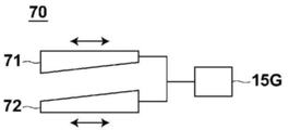
- FIG. 4 is a schematic diagram showing the configuration of the focal length changing optical system.
- the focal length changing optical system 70 includes a circular first wedge prism 71 and a circular second wedge prism 72.
- the seventh operation unit 15G moves the first wedge prism 71 and the second wedge prism 72 in synchronization with each other in opposite directions. Thereby, the focal position of the imaging optical system 14 is changed. Changing the focal position is synonymous with increasing or decreasing the focal length. Therefore, when the focal position of the imaging optical system 14 is changed, the focal length of the imaging optical system 14 is changed.
- changing the focal length of the imaging optical system 14 includes changing the focal length of the imaging lens 14d by the first operation unit 15A, and changing the focal length of the imaging lens 14d by the sixth operation unit 15F. Not only changing the focal length of the imaging optical system 14 but also changing the focal length of the imaging optical system 14 by the seventh operating unit 15G.
- the first and second wedge prisms 71 and 72 are prisms in which two surfaces that can be a light incident surface and a light exit surface are not parallel, that is, the other surface is inclined with respect to one surface.
- a surface arranged perpendicular to the optical axis is referred to as a right-angled surface
- a surface arranged inclined with respect to the optical axis is referred to as a wedge surface.
- the wedge prisms 71 and 72 are prisms that deflect light that is incident perpendicularly to a right angle plane.
- the seventh operation unit 15G includes an actuator such as a piezoelectric element, and sets the first wedge prism 71 and the second wedge prism 72 at right angles based on a control signal output from a focus position evaluation device 30 described later.
- the planes are kept in parallel and moved synchronously in opposite directions. That is, when the first wedge prism 71 is moved rightward in FIG. 4, the second wedge prism 72 is moved leftward. Conversely, when moving the first wedge prism 71 to the left in FIG. 4, the second wedge prism 72 is moved to the right.
- the optical path length of the light emitted from the imaging optical system 14 is changed, whereby the focal position of the imaging optical system 14 is changed. Can be changed to change the focal length. Thereby, the autofocus control is performed, and the contrast of the phase difference image acquired by the imaging unit 16 is adjusted.
- FIG. 5 is a block diagram illustrating a configuration of the microscope observation system according to the first embodiment. Note that, regarding the microscope device 10, a block diagram of a partial configuration controlled by each unit of the microscope control device 20 is shown.
- the microscope control device 20 controls the entire microscope device 10 and includes the focus position evaluation device 30, the scan control unit 21, and the display control unit 22 according to the first embodiment.
- the focus position evaluation device 30 includes a comparison image acquisition unit 31, a discriminator 32, a focus position determination unit 33, an operation control unit 34, and a learning unit 35 of the discriminator 32.
- the discriminator 32 corresponds to the evaluation unit of the present disclosure
- the microscope device 10 corresponds to the imaging device of the present disclosure.
- the microscope control device 20 includes a computer having a CPU (Central Processing Unit) as a central processing unit, a semiconductor memory, a hard disk drive, and the like. And a microscope control program are installed. Then, by executing the focus position evaluation program and the microscope control program by the CPU, the comparison image acquisition unit 31, the discriminator 32, the focus position determination unit 33, the operation control unit 34, the learning unit 35, and the scanning unit shown in FIG.
- the control unit 21 and the display control unit 22 function.
- the CPU executes the function of each unit by the focus position evaluation program and the microscope control program.
- a general-purpose processor that executes software to function as various processing units includes: In addition to the CPU, a programmable logic device (PLD) that can change the circuit configuration after manufacturing such as an FPGA (Field Programmable Gate Array) can be used. Further, the processing of each unit may be performed by a dedicated electric circuit or the like, which is a processor having a circuit configuration specifically designed to execute a specific processing such as an ASIC (Application Specific Integrated Circuit).
- PLD programmable logic device
- ASIC Application Specific Integrated Circuit
- One processing unit may be configured by one of these various processors, or may be a combination of two or more processors of the same type or different types (for example, a plurality of FPGAs or a combination of a CPU and an FPGA). It may be configured. Further, a plurality of processing units may be configured by one processor. As an example of configuring a plurality of processing units with one processor, first, as represented by computers such as a client and a server, one processor is configured by a combination of one or more CPUs and software. There is a form in which a processor functions as a plurality of processing units.
- SoC System On Chip: SoC
- SoC System On Chip
- circuitry an electric circuit in which circuit elements such as semiconductor elements are combined.
- the scanning control unit 21 controls the driving of the horizontal direction driving unit 17, thereby moving the stage 51 in the X direction and the Y direction, and moving the culture container 50 in the X direction and the Y direction.
- the horizontal driving unit 17 is configured by an actuator such as a piezoelectric element.
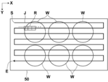
- FIG. 6 is a diagram in which the scanning position according to the observation area in the culture vessel 50 is indicated by a solid line J.
- a well plate having six wells W is used as the culture vessel 50.
- the observation area of the imaging optical system 14 moves along the solid line J from the scanning start point S to the scanning end point E. That is, the observation region R is moved in the positive X direction (right direction in FIG. 6), then in the Y direction (downward in FIG. 6), and in the opposite negative direction (left direction in FIG. 6). Be moved. Next, the observation area R moves again in the Y direction and moves again in the forward direction. As described above, the culture vessel 50 is two-dimensionally scanned by repeatedly performing the reciprocating movement in the X direction and the movement in the Y direction of the observation region R.
- the stage 51 is moved in the X direction and the Y direction, and the observation region of the imaging optical system 14 is moved two-dimensionally in the culture container 50 to scan the culture container 50.
- the invention is not limited thereto, and the imaging optical system 14 may be moved in the X direction and the Y direction, and the observation area of the imaging optical system 14 may be moved two-dimensionally in the culture container 50 to scan the culture container 50. Good.
- an observation image G0 for evaluating the focus position is acquired by the imaging unit 16 before acquiring the phase difference image, the focus position is evaluated, and the focus position is evaluated.
- Autofocus control based on the position is performed, the observation region R is imaged, and a phase difference image is obtained.
- the stage 51 moves, and the autofocus control is performed in the next observation region R to obtain the phase difference image.
- a marker (subject) is included in the culture container 50 in order to evaluate a focus position for performing autofocus control.
- the marker is a fine bead charged into the culture container 50.
- the fine beads are made of resin spheres such as polyester having a diameter of 1 to 2 ⁇ m, for example.
- a marker is not limited to a fine bead.
- the marker include a pattern at the time of processing formed on the surface of the culture container 50 and a fine structure of a cell to be observed contained in the culture container 50 (for example, Nucleolus) can be used.
- the culture container 50 is manufactured by injection molding of a resin material, and a pattern at the time of cutting of the mold formed on the surface of the mold exists on the surface thereof.
- Such a pattern formed on the surface of the culture vessel 50 can be used as a marker. Further, since the fine structure of a cell such as a nucleolus is spherical, the fine structure of such a cell can be used as a marker.
- the comparison image acquisition unit 31 acquires a plurality of comparison images to be compared for the evaluation of the focus position by causing the microscope device 10 to photograph a marker for each different focus position in at least one scanning direction.
- the comparison image acquisition unit 31 scans the observation region R of the imaging optical system 14 in one scanning direction with respect to the culture container 50 containing the marker, and acquires an observation image. Then, the comparison image acquisition unit 31 acquires a comparison image to be compared with the focus position evaluation by detecting the marker image from the acquired observation image.
- the observation image is a phase difference image
- the above-described marker is represented by a contrast different from that of the background image in the phase difference image.
- the comparative image acquisition unit 31 detects the marker image from the observed image and acquires the comparative image by performing threshold processing.
- the comparison image acquisition unit 31 also performs a process of acquiring a marker image from the observation image G0 for focus position evaluation acquired by the imaging unit 16. A specific photographing method for acquiring the comparison image and the observation image G0 for focus position evaluation will be described later in detail.
- the discriminator 32 includes a marker image detected by the comparative image obtaining unit 31 from the observation image G0 for focus position evaluation obtained by imaging the marker M by the microscope device 10 and a scanning direction when the marker M is imaged. It functions as an evaluation unit that evaluates a focus position by comparing a marker image as a comparison image detected from an observation image captured in advance in a corresponding scanning direction. Specifically, the discriminator 32 uses the marker image as the comparison image acquired by the comparison image acquisition unit 31 as a teacher marker image, and learns using the feature amount related to the teacher marker image. The focus position is evaluated by determining the focus position of the input marker image.
- the comparison image is referred to as a teacher marker image.
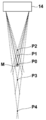
- FIG. 7 is a diagram for explaining image capturing of a marker for acquiring a teacher marker image used for learning of the discriminator 32. Note that, in FIG. 7, photographing of one marker M using fine beads as a marker will be described.
- the microscope device 10 captures the marker M at a plurality of focus positions. That is, first, the user adjusts the imaging optical system 14, performs focus control so as to focus on the position P0 of the marker M, and acquires an image focused on the marker M.
- the observation area R is moved in the positive X direction (rightward in FIG. 6).
- R is moved in the negative X direction (to the left in FIG. 6)
- an observation image of the marker M is acquired.
- the user performs focus control so as to focus on the positions P1 and P2 in front of the marker M, and moves the observation region R in the positive X direction (rightward in FIG. 6).
- the observation area R is moved in the negative X direction (to the left in FIG. 6)
- an observation image defocused in the positive direction is acquired.
- focus control is performed so as to focus on the positions P3 and P4 behind the marker M, and the observation area R is moved in the positive direction in the X direction (rightward in FIG. 6).
- the image is moved in the negative X direction (left direction in FIG. 6)
- an observation image defocused in the negative direction is acquired.
- the marker M is photographed at five focus positions P0 to P4.
- the present invention is not limited to this, and photographing of the marker M may be performed at more or less focus positions. It may be performed.
- the comparison image acquisition unit 31 detects a region including the marker from the observation image acquired by photographing the marker M at a plurality of focus positions as described above, and generates and acquires a teacher marker image.
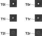
- FIG. 8 is a diagram showing an example of a teacher marker image.
- FIG. 8 shows teacher marker images T01, T11, T21, T0r, T1r, and T2r generated from observation images acquired by focusing on the positions P0, P1, and P2.
- FIG. 9 is a diagram showing teacher marker images in different scanning directions.
- a teacher marker image T01 is a marker image detected from an observation image when the observation area R is moved from the right direction to the left direction in FIG. 6, that is, a negative direction of the X direction
- the teacher marker image T0r is 7 is a marker image detected from an observation image when the observation area R is moved from the left direction to the right direction in FIG. 6, that is, the positive direction in the X direction.
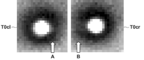
- FIG. 10 is a diagram in which the contrast is increased in the teacher marker image of FIG.
- an image in which the contrast of the teacher marker image T01 in FIG. 9 is enhanced is defined as the teacher marker image T0cl
- an image in which the contrast of the teacher marker image T0r in FIG. 9 is enhanced is defined as the teacher marker image T0cr.
- the teacher's marker image T0cl has a circular white region (a region with a large gray value) representing a fine bead as a marker in the vicinity of the center, in the vicinity indicated by an arrow A in FIG. On the right side of the white region of the shape, there is a white region that protrudes from the circle.
- the protruding white area that is, the area where the white image is trailed is referred to as a trailing area.
- a circular white area representing a fine bead as a marker near the center has a tailing area near the arrow B in FIG. 10, that is, on the left side of the circular white area.
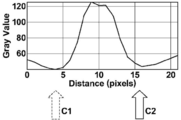
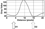
- FIG. 11 is a profile of the center height in the teacher marker image T01 when scanned from right to left
- FIG. 12 is a center height in the teacher marker image T0r when scanned from left to right.
- the horizontal axis indicates Distance (pixels) of the teacher marker images T01 and T0r
- the vertical axis indicates Gray Value.
- Gray Value on the vertical axis is a value indicating brightness. It should be noted that the larger the value of the shading value, the whiter the color.
- the right hem indicated by the arrow C2 is better than the left hem indicated by the arrow C1 in FIG.
- the gray value is large. That is, tailing occurs on the right side.
- the left hem shown by the arrow D1 in FIG. 12 is the same as the right hem shown by the arrow D2 in FIG. In comparison, the gray value is large. That is, tailing occurs on the left side.
- the position where the tailing occurs and the direction of the tailing are different. Therefore, when the teacher's marker image is acquired from the observation image acquired at a fixed position without scanning, no tailing occurs in the teacher's marker image, and the marker image detected from the observation image G0 and the teacher's image are used.
- the focus position is evaluated by comparing the marker image with the marker image, the accuracy of the evaluation is reduced. Therefore, as in the present embodiment, when scanning in the left direction and scanning in the right direction, that is, by acquiring a teacher's marker image using an observation image photographed with a different scanning direction,
- the teacher marker image can also be an image in which tailing has occurred. Accordingly, when the marker image detected from the observation image G0 and the marker image for teacher are collated, the images having the same scanning direction can be collated, so that the accuracy in evaluating the focus position can be improved. it can.
- the comparative image acquisition unit 31 performs imaging in the left and right scanning directions to acquire the teacher marker image, but the technology of the present disclosure is not limited thereto.
- a teacher marker image may be acquired when the observation area R is moved in the positive Y direction (downward in FIG. 6) in FIG.
- shooting may be performed only in one scanning direction such as only the left direction and only the left direction.
- the comparison image acquiring unit 31 acquires, for example, a teacher marker image in one scanning direction, and inverts the pixel position of the acquired teacher marker image, so that the teacher image in the scanning direction opposite to the one scanning direction is obtained.
- a marker image for use may be obtained.
- “reversal” includes a process of mirror reversal about a straight line passing through the center of the teacher marker image and a process of rotating the teacher marker image by 180 °.
- the learning unit 35 associates the focus position with the teacher marker image.
- the teacher marker image acquired at the focus position P0 is associated with 0 as the focus position
- the teacher marker image acquired at the focus position P1 is associated with +6 ⁇ m as the focus position
- the marker image is associated with +12 ⁇ m as the focus position.
- the teacher marker image acquired at the focus position P3 is associated with -6 ⁇ m as the focus position
- the teacher marker image acquired at the focus position P4 is associated with -12 ⁇ m as the focus position.
- the learning unit 35 learns the discriminator 32 so as to determine the focus position of the input marker image using the teacher marker image.
- the determiner 32 determines the focus position of the marker image.
- the discriminator 32 calculates the probability of being the focus position for a plurality of focus positions for the marker image to be determined, and selects the focus position with the highest probability among the input marker images. Is determined as the focus position.
- the learning unit 35 acquires a feature amount in a region of a predetermined size (for example, 3 ⁇ 3 or the like) from the teacher marker image, inputs the acquired feature amount to the discriminator 32, and inputs the acquired feature amount. Learning of the discriminator 32, that is, machine learning, is performed so as to output a discrimination result of a focus position corresponding to the teacher marker image.
- the discriminator 32 includes a support vector machine (SVM), a deep neural network (DNN), a convolutional neural network (CNN), and a recurrent neural network (RNN). Recurrent Neural Network)).
- SVM support vector machine
- DNN deep neural network
- CNN convolutional neural network
- RNN recurrent neural network
- a co-occurrence matrix related to the teacher marker image may be used as the feature amount of the teacher marker image.
- the co-occurrence matrix is a matrix indicating the distribution of signal values of pixels in an image, and expresses the frequency of signal values of pixels adjacent to a pixel having a certain signal value as a matrix.
- the focus position of the marker image is 0, that is, when the marker image is in focus, since the contrast of the marker image is high, the pixel adjacent to the pixel of high luminance (ie, low density) has low luminance (ie, High concentration). For this reason, when the focus position of the marker image is 0, the frequency of adjacent pixels having a high signal value becomes high for pixels of high luminance.
- the marker image when the marker image is blurred, the pixels adjacent to the high-luminance pixels do not have such low luminance. For this reason, when the marker image is blurred, since the contrast of the marker image is low, the frequency of adjacent pixels having a signal value of similar luminance increases with high luminance pixels. For this reason, the co-occurrence matrix for the teacher marker image becomes a characteristic matrix according to the degree of blurring of the marker image. Therefore, by using the co-occurrence matrix as the feature amount, the discriminator 32 can be learned so that the focus position can be accurately discriminated.
- FIG. 13 is a diagram showing a result of determining the defocus amount.
- the marker image is indicated by a white circle.
- the discriminator 32 discriminates a focus position for each of the plurality of marker images included in the observation image G0 as shown in FIG.
- a numerical value ( ⁇ m) indicating a focus position for each marker image is shown near each marker image for explanation.
- the focus position determination unit 33 determines the statistical value of the focus position of the plurality of marker images determined by the determiner 32 as the focus position of the observation image G0 for one observation image G0.
- the statistical value an average value, a median value, a mode value, and the like of the focus positions of a plurality of marker images can be used.
- the statistic is the mode
- the statistic of the focus position is determined to be 7 ⁇ m for the observation image G0 whose focus position has been determined as shown in FIG.
- the operation control unit 34 operates the operation unit 15 to perform autofocus control based on the focus position determined by the focus position determination unit 33 as described above. Specifically, a control signal is output to each of the first to seventh operation units 15A to 15G based on the focus position.
- the focal length of the imaging lens 14d is changed by the first operating unit 15A, and the focal length of the imaging optical system 14 is changed.
- the imaging lens 14d is moved in the optical axis direction by the second operation unit 15B.
- the imaging section 16 is moved in the optical axis direction by the third operation section 15C.
- the stage 51 is moved in the optical axis direction by the fourth operation unit 15D.
- the objective lens 14b is moved in the optical axis direction by the fifth operation unit 15E.
- the focal length of the objective lens 14b is changed by the sixth operating unit 15F, and the focal length of the imaging optical system 14 is changed. Further, the focal position of the imaging optical system 14 is changed by the seventh operating unit 15G, and the focal length of the imaging optical system 14 is changed. Autofocus control is performed by these seven operations.
- the operation control unit 34 performs autofocus control by driving and controlling the operation unit 15 based on the focus position determined in the observation area R.
- the operation control unit 34 includes a focus position, a voltage applied to the imaging lens 14d for changing the focal length of the imaging lens 14d, an amount of movement of the imaging lens 14d in the optical axis direction, and shooting.
- the relationship between the moving distance of the focal length changing optical system 70 and the focal length changing optical system 70 is stored in advance as a table. This table is called a first table.
- the operation control unit 34 refers to the first table based on the determined focus position, and applies a voltage applied to the imaging lens 14d for changing the focal length of the imaging lens 14d,
- the amount of movement in the optical axis direction, the amount of movement of the imaging section 16 in the optical axis direction, the amount of movement of the stage 51 in the optical axis direction, the amount of movement of the objective lens 14b in the optical axis direction, and the focal length of the objective lens 14b are changed.
- the voltage applied to the objective lens 14b and the amount of movement of the focal length changing optical system 70 are obtained.
- the voltage applied to the imaging lens 14d for changing the focal length of the imaging lens 14d, the amount of movement of the imaging lens 14d in the optical axis direction, and the movement of the imaging unit 16 in the optical axis direction Amount, the amount of movement of the stage 51 in the optical axis direction, the amount of movement of the objective lens 14b in the optical axis direction, the voltage applied to the objective lens 14b for changing the focal length of the objective lens 14b, and the The movement amount is called a focus control amount.
- the operation control unit 34 outputs a control signal corresponding to the focus control amount to the first operation unit 15A to the seventh operation unit 15G in order to control the operation unit 15.
- the operation control unit 34 refers to the first table based on the focus position, acquires a focus control amount, and outputs the acquired focus control amount to the first operation unit 15A to the seventh operation unit 15G.
- the operation unit 15, that is, the first operation unit 15A to the seventh operation unit 15G are driven based on the input control signal. Thereby, focus control according to the focus position of the observation area R is performed.
- the display control unit 22 generates one composite phase difference image by combining the phase difference images of each observation region R captured by the microscope device 10 and displays the composite phase difference image. It is displayed on the device 23.
- the display device 23 displays the combined phase difference image generated by the display control unit 22 as described above, and includes, for example, a liquid crystal display or the like. Further, the display device 23 may be configured by a touch panel, and may also be used as the input device 24.
- the input device 24 includes a mouse, a keyboard, and the like, and receives various setting inputs by the user.
- the input device 24 of the present embodiment receives setting inputs such as an instruction to change the magnification of the phase difference lens 14a and an instruction to change the moving speed of the stage 51.
- the focus position is set by the user (step ST1).
- the stage 51 moves to set the observation area R of the imaging optical system 14 to the position of the scanning start point S shown in FIG.
- the scanning by R is started (step ST2).
- the comparison image acquisition unit 31 causes the microscope device 10 to photograph a marker in one scanning direction (step ST3), and acquires a teacher marker image in one scanning direction from the acquired observation image (step ST4).
- the comparison image acquiring unit 31 causes the imaging microscope apparatus 10 to set the marker in the scanning direction opposite to the one scanning direction. Is captured (step ST5), and a teacher image in the reverse scanning direction is acquired from the acquired observation image (step ST6). Then, when the images are not captured at all the focus positions (step ST7; NO), the comparison image acquisition unit 31 shifts the processing to step ST1, and performs the shift processing until the imaging at all the focus positions is completed. Repeat. On the other hand, in step ST7, when shooting at all focus positions has been completed (step ST7; YES), a series of processing ends.
- the comparative image acquiring unit 31 acquires the teacher marker image as the comparative image.
- the culture container 50 containing the cells to be observed is set on the stage 51 (step ST10).
- the cells are observation targets and are markers.
- the stage 51 is moved to set the observation area R of the imaging optical system 14 to the position of the scanning start point S shown in FIG. 6, and scanning by the observation area R is started (step ST12).
- the observation image G0 for focus position evaluation is obtained, the marker image is detected, the focus position is determined, the focus position is determined, and the focus position is determined.
- the control amount is calculated, and autofocus control is performed to obtain a phase difference image of the observation target.
- the observation image G0 for focus position evaluation is acquired by the imaging unit 16 (step ST14), and the comparison image acquisition unit 31 detects a marker image from the observation image G0 (step ST16).
- the discriminator 32 determines the focus position of the marker image included in the observation image G0 (step ST18), and the focus position determination unit 33 determines the focus position in the observation area R (step ST20).
- the operation control unit 34 calculates a focus control amount based on the determined focus position (step ST22), and performs autofocus control based on the focus control amount (step ST24).
- the operation control unit 34 drives and controls the operation unit 15 based on the movement amount stored in advance, changes the focal length of the imaging lens 14d, and moves the imaging lens 14d, the imaging unit 16 and the objective lens 14b to Z. Move in the direction. Then, after the autofocus control, the imaging unit 16 captures an image of the observation region R and acquires a phase difference image of the observation target in the observation region R (step ST26). The acquired phase difference image is output from the imaging unit 16 to the display control unit 22 and stored.
- step ST28; NO If not all scans have been completed (step ST28; NO), the observation area R moves in the X direction or the Y direction, and the acquisition of the above-described observation image G0 and the marker until all scans are completed.
- the detection of the image, the determination of the focus position, the determination of the focus position, the calculation of the focus control amount, the automatic focus control, and the acquisition of the phase difference image of the observation target are repeatedly performed (step ST14 to step ST26). Then, when the observation region R reaches the position of the scanning end point E shown in FIG. 6, all scanning ends (step ST28; YES).
- the display control unit 22 combines the phase difference images of the observation regions R to generate a combined phase difference image (step ST30), and displays the generated combined phase difference image on the display device 23. (Step ST32).
- the observation image G0 for focus position evaluation including the marker whose focus position is to be evaluated is obtained, the marker image is detected from the observation image G0, and the image is captured with various defocus amounts. Learning is performed using the feature amounts related to the plurality of teacher marker images, and the focus position is determined by the determiner 32 that determines the focus position of the input marker image. Therefore, the focus position can be quickly evaluated with a small amount of calculation.
- the discriminator determines the focus position of each of the plurality of marker images included in the observation image G0, and determines the statistical value of the plurality of focus positions as the focus position of the observation region R where the observation image G0 is obtained. 32, the focus position can be determined with high accuracy. Further, by focusing the image of the observation target in the culture vessel 50 on the imaging unit 16 based on the focus position, the focus position can be determined at high speed, so that the autofocus control can be performed at high speed. .
- the teacher marker image is obtained by photographing the marker at each of different focus positions in at least one scanning direction
- the teacher marker image is also obtained with the trailing image. can do. Accordingly, when the marker image detected from the observation image G0 and the marker image for teacher are collated, the images having the same scanning direction can be collated, so that the accuracy in evaluating the focus position can be improved. it can.
- the focus position evaluation device 30 is applied to a microscope imaging system, and the observation area R is moved while using the observation target cell as a marker.
- R acquisition of the observation image G0, detection of the marker image, determination of the focus position, determination of the focus position, calculation of the focus control amount, autofocus control, and acquisition of the phase difference image of the observation target are performed. It is not limited. For example, for a certain culture container 50, cells are not stored, but a marker different from cells is stored, and in each observation region R in the culture container 50, an observation image G0 is obtained, a marker image is detected, a focus position is determined, The determination of the focus position and the calculation of the focus control amount may be performed.
- the cells contained in the same type of culture container 50 as the culture container 50 for which the defocus amount has been determined are set as observation targets, and the phase difference image Acquisition is performed.
- the focus position is determined prior to the acquisition of the phase difference image, it is preferable to use fine beads as markers.
- this will be described as a second embodiment.
- FIG. 16 is a flowchart illustrating a process performed in the second embodiment for determining a focus position before acquiring a phase difference image.
- the culture container 50 containing the microbeads as markers is set on the stage 51 (step ST40).
- the stage 51 is moved to set the observation area R of the imaging optical system 14 to the position of the scanning start point S shown in FIG. 6, and scanning by the observation area R is started (step ST42).
- the observation image G0 for focus position evaluation is acquired by the imaging unit 16 (step ST44), and the comparison image acquisition unit 31 detects a marker image from the observation image G0 (step ST46).
- the discriminator 32 determines the focus position of the marker image included in the observation image G0 (step ST48), and the focus position determination unit 33 determines the focus position in the observation region R (step ST50).
- the operation control unit 34 calculates a focus control amount based on the determined focus position (step ST52), and stores the focus control amount in association with the position on the XY coordinates of the detection position of the culture vessel 50. (Step ST54).
- step ST56 If all the scans have not been completed (step ST56; NO), the observation area R moves in the X direction or the Y direction, and the acquisition of the above-described observation image G0 and the marker until all the scans are completed.
- the detection of the image, the determination of the focus position, the determination of the focus position, the calculation of the focus control amount, and the storage of the focus control amount are repeatedly performed (steps ST44 to ST54). Then, when the observation region R reaches the position of the scanning end point E shown in FIG. 6, all scanning ends (step ST56; YES).
- the culture container 50 when acquiring the phase difference image of the observation target, the culture container 50 is scanned and the phase difference image is acquired in each observation region R, as in the case of determining the focus position.
- the operation control unit 34 performs autofocus control using the focus control amount stored in association with the XY coordinates of the culture container 50 corresponding to the observation area R.
- acquisition of a phase difference image is performed while performing focus control in each observation region R.
- the observation image G0 detects the marker image, determine the focus position, determine the focus position, calculate the focus control amount, perform the autofocus control, and obtain the phase difference image.
- the observation region R can be continuously operated on the culture container 50, so that a phase difference image can be obtained at a higher speed.
- the operation control unit 34 stores the focus control amount in each observation region R, but may store the determined focus position. In this case, when acquiring a phase difference image in each observation region R, a focus control amount is calculated based on the stored focus position, and photographing of the observation region R and acquisition of the phase difference image are performed.
- the “notifying unit” is a “notifying unit” that is a display that visually displays a message or the like, a sound reproducing device that displays an audible sound when a sound is output, or a permanently-visible sound that is recorded on a recording medium such as paper. It means a printer to be displayed, communication means such as e-mail and telephone, an indicator light, and the like, and may be a combination of at least two or more of the display, the audio reproducing device, the printer, the communication means, and the indicator light.
- both the image defocused in the plus direction and the image defocused in the minus direction are used as the teacher marker images used when the discriminator 32 learns.
- the image defocused in the plus direction and the image defocused in the minus direction are similar, even if the discriminator 32 that has learned using such a teacher marker image is used, the focus position can be reduced. It may be difficult to determine whether is a plus side focus position or a minus side focus position.
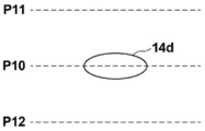
- FIG. 17 is a diagram for explaining the auto focus control. Note that FIG. 17 illustrates autofocus control when the imaging lens 14d is moved in the Z direction. As shown in FIG. 17, it is assumed that the focus position when the imaging lens 14d is at the position P10 is determined to be + ⁇ . In this case, if the actual focus position is plus (that is, a state in which the imaging lens 14d is focused farther than the observation target), the imaging lens 14d is moved away from the observation target, for example, to a position P11. By moving, the observation target can be focused. However, in actuality, the focus is closer to the imaging lens 14d than the observation target, and when the focus position is ⁇ , the focus becomes less focused by moving the imaging lens 14d to the position P11.
- the focus position when the imaging lens 14d is at the position P10 is determined to be + ⁇ .
- the actual focus position is plus (that is, a state in which the imaging lens 14d is focused farther than the observation target)
- the imaging lens 14d is moved away from the observation target, for
- the operation control unit 34 moves the imaging lens 14d in a direction approaching the observation target, for example, from the position P11 to the position P12.
- the focus control amount is determined so as to move.
- the auto focus control when performing autofocus control by judging the contrast of an image as in the related art, it is necessary to repeat the acquisition of the observation image G0 and the determination of the focus control amount until the observation object is focused.
- the accurate focus control amount can be determined only by performing the operation of determining the focus position again. Therefore, in the present embodiment, even if the focus control amount is erroneously determined to be plus or minus, the auto focus control can be performed at high speed.
- the discriminator 32 may be used as a learning marker image. For example, when learning of the discriminator 32 is performed using only the image defocused in the plus direction as the teacher marker image, the determined focus position has a positive value. In this case, when the actual focus position is minus, as shown in FIG. 17, when the imaging lens 14d is moved to the position P11 as in the case where the focus position is plus, the focus is further reduced.
- the operation control unit 34 adjusts the focus control amount so as to move the imaging lens 14d from the position P11 to the position P12. decide.
- an accurate focus control amount can be determined only by performing the operation of determining the focus position again. Therefore, even if only one of the image defocused in the plus direction and the image defocused in the minus direction is used as the teacher marker image and the learning of the discriminator 32 is performed, the autofocus control can be performed at high speed. It can be carried out.
- a marker image with a known focus position is used as a teacher marker image for learning the discriminator 32, but the present invention is not limited to this.
- a marker image whose focus position is unknown may be used as a teacher marker image.
- the learning unit 35 learns the discriminator 32 so as to determine that the focus position is unknown.
- a marker image whose focus position is unknown a marker image whose focus position has been erroneously determined as a result of input to the discriminator 32 can be used. For this reason, the learning unit 35 first performs learning so that the discriminator 32 does not determine that the focus position is unknown.
- the marker image in which the focus position is erroneously determined is determined to be a marker image whose focus position is unknown.
- the discriminator 32 learns again using such a marker image so as to discriminate that the focus position is unknown.
- the discriminator 32 capable of discriminating that the focus position is unknown. Therefore, it is possible to reduce the possibility that an erroneous focus position determination result is obtained.
- the operating unit 15 performs the autofocus control using the first to seventh operating units 15A to 15G, but any one of the first to seventh operating units 15A to 15G. Autofocus control may be performed using only one or a plurality of these. Further, only one of the first to seventh operation units 15A to 15G or a plurality of them may be provided.
- the focal length changing optical system 70 is disposed between the imaging optical system 14 and the photographing unit 16, but is disposed between the imaging optical system 14 and the stage 51. You may.
- the culture vessel 50 is moved in the optical axis direction by moving the stage 51 in the optical axis direction by the fourth operation unit 15D.
- a mechanism for moving the culture vessel 50 in the optical axis direction may be provided, and only the culture vessel 50 may be moved in the optical axis direction.
- the discriminator 32 determines the focus position of the marker image detected from the observation image G0 by the comparison image acquisition unit 31.
- the presence / absence of the marker image in the observation image G0 may be determined only by the determiner, and when the marker image is included, the focus position of the marker image may be determined.
- the comparison image acquisition unit 31 acquires the teacher marker image by photographing the marker at each different focus position in at least one scanning direction. May be further obtained for each scanning speed. In this case, the focus position evaluation accuracy can be further improved.
- FIG. 18 is a block diagram illustrating a schematic configuration of a microscope observation system to which the focus position evaluation device according to the third embodiment of the present disclosure is applied.
- the microscope observation system according to the third embodiment includes, in the configuration diagram shown in FIG. 5, an image acquisition unit 36 that acquires a plurality of photographed images by photographing a marker at each different focus position.
- the image acquisition unit 36 acquires a captured image at a fixed position without scanning the observation area.
- the image acquisition unit 36 sets focus positions at intervals of 1 ⁇ m between ⁇ 50 ⁇ m and +50 ⁇ m, for example, and acquires images photographed at each focus position.
- the comparison image acquisition unit 31A in the third embodiment creates a teacher marker image as a comparison image having features based on the scanning direction based on the captured image acquired by the image acquisition unit 36.
- the comparison image acquisition unit 31A generates a comparison image to be compared with the focus position evaluation for each scanning direction based on the plurality of captured images, and acquires a plurality of the generated comparison images.
- the comparison image is generated by performing a convolution process with a blur function on each of the plurality of captured images.
- the “blur function” will be described.
- the “blur function” of the present disclosure is a function for quantifying the above-described tailing region, and is also referred to as a tailing function.
- FIG. 19 is a graph showing the profile of the pulse light source.
- the vertical axis represents the light intensity of the white light source 11
- the horizontal axis represents time.
- the tailing function correlates with the profile of the pulse light source shown in FIG. 19, that is, the function of the intensity change of the white light source 11 over time.
- the comparison image acquisition unit 31A detects a marker image in the captured image at each focus position acquired by the image acquisition unit 36, and performs a convolution process on the detected marker image with the function of the position, thereby obtaining one image. Generate a comparison image in the scanning direction. Further, the pulse waveform obtained by reversing the direction of the pulse waveform in FIG. 19 is converted into a position function in the same manner as described above, and convolution processing is performed on each of the detected marker images. A comparison image in the opposite scanning direction is generated.
- the comparison image in the opposite scanning direction is not limited to the above-described generation method, and may be generated by, for example, inverting the generated comparison image in one scanning direction.
- the image taken by actually scanning as in the first and second embodiments is used as the comparative image.
- the evaluation unit uses, for example, the pixel value of the marker image included in the observation image G0 for focus position evaluation and the pixel value of the marker image included in each of the plurality of observation images acquired in advance as the comparison image. , Calculate correlation values for all combinations.
- the correlation value is equal to or greater than a preset threshold
- the evaluation unit determines that the combination of the observation image G0 having the correlation value and the comparison image is a combination to be associated, and acquires the comparison image.
- the determined focus position is determined as the focus position of the observation image G0.
- the correlation value may be calculated using a zero-mean normalized cross-correlation (ZNCC).
- ZNCC zero-mean normalized cross-correlation
- the present invention is not limited to this, and another calculation method may be used.
- the comparison image acquisition unit 31 and the comparison image acquisition unit 31A cause the microscope device 10 or the image acquisition unit 36 to acquire an image and generate a comparison image from the acquired image.
- the technology of the present disclosure is not limited to this.
- the comparative image acquiring unit 31 and the comparative image acquiring unit 31A acquire, from the database, an image photographed by the comparative image acquiring unit 31 or an imaging device not under the control of the comparative image acquiring unit 31A and stored in the database, A comparison image may be generated from the obtained image.
- the comparison image acquisition unit 31 and the comparison image acquisition unit 31A may acquire an externally generated comparison image.
- the focus position evaluation apparatus according to the present invention is applied to a phase contrast microscope.
- the present invention is not limited to the phase contrast microscope, and may be applied to other microscopes such as a differential interference microscope and a bright field microscope. May be applied.
- Microscope device (imaging device) 11 White light source 12 Condenser lens 13 Slit plate 14 Imaging optical system 14a Phase difference lens 14b Objective lens 14c Phase plate 14d imaging lens 15 Working part 15A first operation unit 15B 2nd operation part 15C 3rd operation part 15D fourth operation unit 15E Fifth operation unit 15F 6th operation part 15G 7th operation part 16 Shooting unit 17 Horizontal drive 20 Microscope control device 21 Scanning control unit 22 Display control unit 23 Display device 24 Input device 30 Focus position evaluation device 31, 31A Comparative image acquisition unit 32 classifier (evaluation unit) 33 Focus Position Determination Unit 34 Operation control unit 35 Learning Department 36 Image acquisition unit 50 culture vessel 51 stages 51a opening 70 Focal length changing optical system 71 First wedge prism 72 Second wedge prism J Scan position by observation area S scanning start point E Scan end point L Illumination light R observation area W Well
Landscapes
- Physics & Mathematics (AREA)
- General Physics & Mathematics (AREA)
- Optics & Photonics (AREA)
- Engineering & Computer Science (AREA)
- Chemical & Material Sciences (AREA)
- Analytical Chemistry (AREA)
- Multimedia (AREA)
- Signal Processing (AREA)
- Computer Vision & Pattern Recognition (AREA)
- Microscoopes, Condenser (AREA)
- Automatic Focus Adjustment (AREA)
- Focusing (AREA)
Abstract
フォーカス位置評価装置、方法、及びプログラムにおいて、フォーカス位置の評価の精度を向上させる。観察対象に対して観察域を走査し、各観察域を撮影する撮影装置のフォーカス位置を評価するフォーカス位置評価装置であって、少なくとも1つの走査方向において、異なるフォーカス位置毎に観察対象を撮影することによりフォーカス位置の評価の比較対象となる比較画像を複数取得する比較画像取得部と、撮影装置によって観察対象を撮影することにより取得された観察画像と、観察対象を撮影する際の走査方向に対応する走査方向の比較画像とを照合することにより、フォーカス位置を評価する評価部と、を含む。
Description
本開示の技術は、フォーカス位置評価装置、方法、及びプログラムに関する。
従来、ES(Embryonic Stem)細胞及びiPS(Induced Pluripotent Stem)細胞等の多能性幹細胞や分化誘導された細胞等を顕微鏡等で撮影し、その画像の特徴を捉えることで細胞の分化状態などを判定する方法が提案されている。そして、ES細胞及びiPS細胞等の多能性幹細胞は、種々の組織の細胞に分化する能力を備えており、再生医療、薬の開発、病気の解明などにおいて応用が可能な細胞として注目されている。細胞を顕微鏡で撮影する際には、高倍率な広視野画像を取得するため、例えばウェルプレート等の培養容器の範囲内を結像光学系によって走査し、観察位置毎の画像を撮影した後、その観察位置毎の画像を結合する、いわゆるタイリング撮影を行うことが提案されている。
しかしながら、培養容器として例えば複数のウェルを有するウェルプレートを使用する場合、各ウェルの底部の厚さは、製造上の誤差等に起因してウェル毎に異なる。そのため、ウェルプレート全体を結像光学系によって走査することによりタイリング撮影を行う場合には、観察対象を明瞭に撮影するために各観察位置についてフォーカス位置を調整するオートフォーカス制御を行なう必要がある。オートフォーカス制御を行なう場合、例えば観察対象が細胞のように高さや形状が安定しないものである場合には、顕微鏡で撮影する際に観察対象が変化したのか、顕微鏡の状態が変化したのかを判別するのが困難である。そこで、例えば特許文献1において、透過光に対して位相変化及び振幅変化の少なくとも一方を与えるマークを有する透光性部材により、撮影対象となる試料を固定し、試料の像とマークの像とが混在した撮像画像を取得し、この撮影画像について算出した評価値と、予め取得した試料の像を含まない基準画像について算出した評価値とに基づいて、フォーカス位置を評価する方法が提案されている。
また、特許文献2には、例えば位相差光学系利用したオートフォーカス装置においては、デフォーカス量が大きくなり過ぎると、一組の位相差像から得られる位相差(視差)を特定するための局所領域が位相差像から逸脱してしまうため、位相差像における観測面がデフォーカス量の検出可能範囲内に収まっている必要があることが記載されている。特許文献2においては、デフォーカス量の検出可能範囲内に収まっているか否かを評価するために、異なるフォーカス位置において取得された基準画像(以下、比較画像ともいう)と、観察対象画像とを照会することによりフォーカス位置を評価する方法が開示されている。
一方、フォーカス位置を安定して評価するためには、例えば球体を有する微細ビーズをマーカとして使用することが考えられる。しかしながら、撮影時に微細ビーズが静止している場合は、撮影画像において微細ビーズは円形状であるが、上記タイリング撮影をする場合には、微細ビーズが収容された容器及び撮影光学系の少なくとも一方を動かすため、撮影時に微細ビーズが動いた状態となり、微細ビーズ像の焦点の光像が流れてしまい、取得された撮影画像においては、微細ビーズは円形状ではなく、円形状の像が尾引きされた画像となってしまう。従って、単にフォーカス位置毎に微細ビーズを撮影して取得した撮影画像を比較画像として使用する場合には、タイリング撮影によって取得された撮影画像と比較画像とを照合することによりフォーカス位置を評価する際の評価の精度が低下してしまう可能性がある。
本開示は上記事情に鑑みなされたものであり、フォーカス位置の評価の精度を向上させることを目的とする。
本開示のフォーカス位置評価装置は、被写体が収容された容器が設置されるステージと容器内の被写体の像を結像させる結像光学系との少なくとも一方を走査方向に移動することで容器に対して観察域を走査し、各観察域を撮影する撮影装置のフォーカス位置を評価するフォーカス位置評価装置であって、
容器に対して少なくとも1つの走査方向に観察域を走査し、撮影装置によって異なるフォーカス位置毎に被写体を撮影することによりフォーカス位置の評価の比較対象となる比較画像を複数取得する比較画像取得部と、
容器に対して観察域を走査し、撮影装置によって被写体を撮影することにより取得された観察画像と、被写体を撮影する際の走査方向に対応する走査方向の前記比較画像とを照合することにより、フォーカス位置を評価する評価部と、
を含む。
また、本開示のフォーカス位置評価装置においては、比較画像取得部は、一走査方向及びこの一走査方向とは逆向きの走査方向の少なくとも一方において被写体を撮影することにより比較画像を複数取得することができる。
また、本開示のフォーカス位置評価装置においては、比較画像取得部は、一走査方向において被写体を撮影することにより一走査方向の比較画像を複数取得し、かつ、取得した複数の一走査方向の比較画像の各々の画素位置を反転させることにより、一走査方向とは逆向きの走査方向の比較画像を複数取得することができる。
本開示の他のフォーカス位置評価装置は、被写体が収容された容器が設置されるステージと容器内の被写体の像を結像させる結像光学系との少なくとも一方を走査方向に移動することで容器に対して観察域を走査し、各観察域を撮影する撮影装置のフォーカス位置を評価するフォーカス位置評価装置であって、
観察域において、異なるフォーカス位置毎に被写体を撮影することにより複数の撮影画像を取得する画像取得部と、
複数の撮影画像に基づいて、走査方向毎にフォーカス位置の評価の比較対象となる比較画像を生成し、生成された比較画像を複数取得する比較画像取得部と、
撮影装置によって被写体を撮影することにより取得された観察画像と、被写体を撮影する際の走査方向に対応する走査方向の比較画像とを照合することにより、フォーカス位置を評価する評価部と、
を含む。
なお、本開示の上述したフォーカス位置評価装置においては、複数の比較画像は、異なる走査速度毎に取得されてもよい。
また、本開示の上述したフォーカス位置評価装置においては、被写体がマーカであってもよい。
また、本開示の上述したフォーカス位置評価装置においては、マーカが、細胞の微細構造を備えていてもよく、また、本開示の上述したフォーカス位置評価装置においては、マーカが、微細ビーズであってもよい。
また、本開示の上述したフォーカス位置評価装置においては、被写体が、細胞であってもよい。
また、本開示の上述したフォーカス位置評価装置においては、撮影装置が、顕微鏡装置であってもよい。
本開示のフォーカス位置評価方法は、被写体が収容された容器が設置されるステージと容器内の被写体の像を結像させる結像光学系との少なくとも一方を走査方向に移動することで容器に対して観察域を走査し、各観察域を撮影する撮影装置のフォーカス位置を評価するフォーカス位置評価方法であって、
容器に対して少なくとも1つの走査方向に観察域を走査し、撮影装置によって異なるフォーカス位置毎に被写体を撮影することによりフォーカス位置の評価の比較対象となる比較画像を複数取得し、
容器に対して観察域を走査し、撮影装置によって被写体を撮影することにより取得された観察画像と、被写体を撮影する際の走査方向に対応する走査方向の前記比較画像とを照合することにより、フォーカス位置を評価する。
また、本開示の上述したフォーカス位置評価装置においては、比較画像取得部は、撮影画像から走査方向に基づく特徴を有する比較画像を作成してもよい。
また、本開示の別のフォーカス位置評価方法は、被写体が収容された容器が設置されるステージと容器内の被写体の像を結像させる結像光学系との少なくとも一方を走査方向に移動することで容器に対して観察域を走査し、各観察域を撮影する撮影装置のフォーカス位置を評価するフォーカス位置評価方法であって、
観察域において、異なるフォーカス位置毎に被写体を撮影することにより複数の撮影画像を取得し、
複数の撮影画像に基づいて、走査方向毎にフォーカス位置の評価の比較対象となる比較画像を生成し、生成された比較画像を複数取得し、
撮影装置によって被写体を撮影することにより取得された観察画像と、被写体を撮影する際の走査方向に対応する走査方向の比較画像とを照合することにより、フォーカス位置を評価する。
なお、本開示によるフォーカス位置評価方法をコンピュータに実行させるためのプログラムとして提供してもよい。
本開示による他のフォーカス位置評価装置は、被写体が収容された容器が設置されるステージと容器内の被写体の像を結像させる結像光学系との少なくとも一方を走査方向に移動することで容器に対して観察域を走査し、各観察域を撮影する撮影装置のフォーカス位置を評価するフォーカス位置評価装置であって、コンピュータに実行させるための命令を記憶するメモリと、
記憶された命令を実行するよう構成されたプロセッサとを備え、プロセッサは、
容器に対して少なくとも1つの走査方向に観察域を走査し、撮影装置によって異なるフォーカス位置毎に被写体を撮影することによりフォーカス位置の評価の比較対象となる比較画像を複数取得し、
容器に対して観察域を走査し、撮影装置によって被写体を撮影することにより取得された観察画像と、被写体を撮影する際の走査方向に対応する走査方向の比較画像とを照合することにより、フォーカス位置を評価する処理を実行する。
また、本開示によるさらに他のフォーカス位置評価装置は、被写体が収容された容器が設置されるステージと容器内の被写体の像を結像させる結像光学系との少なくとも一方を走査方向に移動することで容器に対して観察域を走査し、各観察域を撮影する撮影装置のフォーカス位置を評価するフォーカス位置評価装置であって、コンピュータに実行させるための命令を記憶するメモリと、
記憶された命令を実行するよう構成されたプロセッサとを備え、プロセッサは、
観察域に対して、異なるフォーカス位置毎に被写体を撮影することにより複数の撮影画像を取得し、
複数の撮影画像に基づいて、走査方向毎にフォーカス位置の評価の比較対象となる比較画像を生成し、生成された比較画像を複数取得し、
撮影装置によって被写体を撮影することにより取得された観察画像と、被写体を撮影する際の走査方向に対応する走査方向の前記比較画像とを照合することにより、フォーカス位置を評価する処理を実行する。
本開示の一実施形態によれば、フォーカス位置の評価の精度を向上させることができる。
以下、本発明の実施形態によるフォーカス位置評価装置、方法及びプログラムの一実施形態を適用した顕微鏡撮影システムについて、図面を参照しながら詳細に説明する。図1は、本開示の第1の実施形態のフォーカス位置評価装置を適用した顕微鏡撮影システムにおける顕微鏡装置の概略構成を示す模式図である。
顕微鏡装置10は、観察対象である培養された細胞の位相差画像を撮影する。具体的には、顕微鏡装置10は、図1に示すように、白色光を出射する白色光源11、コンデンサレンズ12、スリット板13、結像光学系14、動作部15、及び撮影部16を備える。また、顕微鏡装置10は、焦点距離変更光学系70を備える。
動作部15は、第1の動作部15A、第2の動作部15B、第3の動作部15C、第4の動作部15D、第5の動作部15E、第6の動作部15F及び第7の動作部15Gを備える。第1~第7の動作部15A~15Gの動作は後述する。
スリット板13は、白色光源11から出射された白色光を遮光する遮光板に対して白色光を透過するリング形状のスリットが設けられたものであり、白色光がスリットを通過することによってリング状の照明光Lが形成される。
結像光学系14は、培養容器50の範囲内を分割した観察域毎の位相差像を撮影部16に結像する。図2は、結像光学系14の詳細な構成を示す図である。図2に示すように、結像光学系14は、位相差レンズ14a及び結像レンズ14dを備える。また、位相差レンズ14aは、対物レンズ14b及び位相板14cを備える。位相板14cは、照明光Lの波長に対して透明な透明板に対して位相リングを形成したものである。なお、上述したスリット板13のスリットの大きさは、位相板14cの位相リングと共役な関係にある。
位相リングは、入射された光の位相を1/4波長ずらす位相膜と、入射された光を減光する減光フィルタとがリング状に形成されたものである。位相リングに入射された直接光は、位相リングを通過することによって位相が1/4波長ずれ、かつその明るさが弱められる。一方、観察対象によって回折された回折光は大部分が位相板14cの透明板を通過し、その位相及び明るさは変化しない。
対物レンズ14bを有する位相差レンズ14aは、図1に示す動作部15の第5の動作部15Eによって、対物レンズ14bの光軸方向に移動される。本実施形態においては、対物レンズ14bの光軸方向とZ方向(鉛直方向)とは同じ方向である。対物レンズ14bのZ方向への移動によってオートフォーカス制御が行われ、撮影部16によって取得される位相差画像のコントラストが調整される。
また、位相差レンズ14aの倍率を変更可能な構成としてもよい。具体的には、異なる倍率を有する位相差レンズ14a又は結像光学系14を交換可能に構成するようにしてもよい。位相差レンズ14a又は結像光学系14の交換は、自動的に行うようにしてもよいし、ユーザが手動で行うようにしてもよい。
また、対物レンズ14bは、焦点距離を変更可能な液体レンズからなる。なお、焦点距離を変更可能であれば、液体レンズに限定されるものではなく、液晶レンズ及び形状変形レンズ等、任意のレンズを用いることができる。対物レンズ14bは、図1に示す動作部15における第6の動作部15Fによって、印加される電圧が変更されて、焦点距離が変更される。これにより、結像光学系14の焦点距離が変更される。対物レンズ14bの焦点距離の変更によってもオートフォーカス制御が行われ、撮影部16によって取得される位相差画像のコントラストが調整される。
結像レンズ14dは、位相差レンズ14aを通過した位相差像が入射され、これを撮影部16に結像する。本実施形態において、結像レンズ14dは、焦点距離を変更可能な液体レンズからなる。なお、焦点距離を変更可能であれば、液体レンズに限定されるものではなく、液晶レンズ及び形状変形レンズ等、任意のレンズを用いることができる。結像レンズ14dは、図1に示す動作部15における第1の動作部15Aによって、印加する電圧が変更されて、焦点距離が変更される。これにより、結像光学系14の焦点距離が変更される。結像レンズ14dの焦点距離の変更によってオートフォーカス制御が行われ、撮影部16によって取得される位相差画像のコントラストが調整される。
また、結像レンズ14dは、図1に示す動作部15における第2の動作部15Bによって結像レンズ14dの光軸方向に移動される。なお、本実施形態においては、結像レンズ14dの光軸方向とZ方向(鉛直方向)とは同じ方向である。結像レンズ14dのZ方向への移動によってオートフォーカス制御が行われ、撮影部16によって取得される位相差画像のコントラストが調整される。
撮影部16は、結像レンズ14dによって結像された位相差画像を取得する。撮影部16は、CCD(Charge-Coupled Device)イメージセンサ又はCMOS(Complementary Metal-Oxide Semiconductor)イメージセンサ等の撮像素子を備える。撮像素子は、RGB(Red Green Blue)のカラーフィルタが設けられた撮像素子を用いてもよいし、モノクロの撮像素子を用いるようにしてもよい。
また、撮影部16は、図1に示す動作部15における第3の動作部15CによってZ方向に移動される。なお、本実施形態においては、撮影部16の撮像面に垂直な方向とZ方向とは同じ方向である。撮影部16のZ方向への移動によってオートフォーカス制御が行われ、撮影部16によって取得される位相差画像のコントラストが調整される。
スリット板13と結像光学系14との間には、ステージ51が設けられている。ステージ51上には、観察対象である細胞が収容される培養容器50が設置される。
培養容器50としては、観察対象を収容することができればどのような形態を有するものであってもよい。例えば、シャーレ、ディッシュ、フラスコ又はウェルプレート等のように、底部及び底部に連続する壁部を有する形態を有するものを容器として用いることができる。また、板状の部材に微細な流路が形成されたマイクロ流路デバイス等を容器として用いることもできる。さらに、スライドガラスのように、板状の形態を有するものも容器として用いることができる。また、培養容器50に収容される細胞としては、iPS細胞及びES細胞といった多能性幹細胞、幹細胞から分化誘導された神経、皮膚、心筋及び肝臓の細胞、並びに人体から取り出された皮膚、網膜、心筋、血球、神経及び臓器の細胞等がある。
ステージ51は、後述する水平方向駆動部17(図5参照)によって互いに直交するX方向及びY方向に移動するものである。X方向及びY方向は、Z方向に直交する方向であり、水平面内において互いに直交する方向である。本実施形態においては、X方向を主走査方向とし、Y方向を副走査方向とする。
図3は、ステージ51の一例を示す図である。ステージ51の中央には、矩形の開口51aが形成されている。この開口51aを形成する部材の上に培養容器50が設置され、培養容器50内の細胞の位相差画像が開口51aを通過するように構成されている。
また、ステージ51は、第4の動作部15DによってZ方向に移動され、これにより、培養容器50がZ方向に移動される。第4の動作部15Dは、例えば圧電素子等のアクチュエータを備える。本実施形態においては、ステージ51における培養容器50が設置される面に垂直な方向とZ方向とは同じ方向である。ステージ51のZ方向への移動によってもオートフォーカス制御が行われ、撮影部16によって取得される位相差画像のコントラストが調整される。
第1の動作部15A及び第6の動作部15Fは、例えば電圧可変回路を備えたものである。第1の動作部15Aは、後述するフォーカス位置評価装置30から出力された制御信号に基づいて、結像レンズ14dに印加する電圧を変更する。第6の動作部15Fは、後述するフォーカス位置評価装置30から出力された制御信号に基づいて、対物レンズ14bに印加する電圧を変更する。
第2の動作部15B、第3の動作部15C、第4の動作部15D及び第5の動作部15Eは、例えば圧電素子等のアクチュエータを備えたものであり、後述するフォーカス位置評価装置30から出力された制御信号に基づいて駆動する。なお、動作部15は、位相差レンズ14a及び結像レンズ14dを通過した位相差像をそのまま通過させる構成となっている。また、第2の動作部15B、第3の動作部15C、第4の動作部15D及び第5の動作部15Eの構成は圧電素子に限らず、結像レンズ14d、撮影部16、ステージ51及び対物レンズ14b(位相差レンズ14a)をZ方向に移動可能なものであればよく、その他の公知な構成を用いることができる。
図4は焦点距離変更光学系の構成を示す概略図である。図4に示すように、焦点距離変更光学系70は、円形の第1のウェッジプリズム71及び円形の第2のウェッジプリズム72を備える。第7の動作部15Gは、第1のウェッジプリズム71及び第2のウェッジプリズム72を、互いに反対方向に同期させて移動させる。これにより、結像光学系14の焦点位置が変更される。焦点位置が変更されることは、焦点距離が長くなったり短くなったりすることと同義である。このため、結像光学系14の焦点位置が変更されることにより、結像光学系の14の焦点距離が変更される。本実施形態においては、結像光学系14の焦点距離を変更することは、第1の動作部15Aにより結像レンズ14dの焦点距離を変更すること、及び第6の動作部15Fにより対物レンズ14bの焦点距離を変更することのみならず、第7の動作部15Gにより結像光学系14の焦点位置を変更することにより、結像光学系14の焦点距離を変更することも含む。
第1及び第2のウェッジプリズム71,72は、光の入射面及び出射面となり得る2つの面が平行でない、すなわち一方の面に対して他方の面が傾斜しているプリズムである。なお、以降の説明においては、光軸に対して垂直に配置される面を直角面、光軸に対して傾斜して配置される面をウェッジ面と称する。ウェッジプリズム71,72は、直角面に垂直に入射した光を偏向させるプリズムである。第7の動作部15Gは、例えば圧電素子等のアクチュエータを備え、後述するフォーカス位置評価装置30から出力された制御信号に基づいて、第1のウェッジプリズム71及び第2のウェッジプリズム72を、直角面を平行に維持しつつ、互いに反対方向に同期させて移動させる。すなわち、第1のウェッジプリズム71を図4における右方向に移動させる場合には、第2のウェッジプリズム72を左方向に移動させる。逆に、第1のウェッジプリズム71を図4における左方向に移動させる場合には、第2のウェッジプリズム72を右方向に移動させる。このように、第1及び第2のウェッジプリズム71,72を移動させることにより、結像光学系14から出射された光の光路長が変更され、これにより、結像光学系14の焦点位置を変更して焦点距離を変更することができる。これにより、オートフォーカス制御が行われ、撮影部16によって取得される位相差画像のコントラストが調整される。
次に、顕微鏡装置10を制御する顕微鏡制御装置20の構成について説明する。図5は、第1の実施形態の顕微鏡観察システムの構成を示すブロック図である。なお、顕微鏡装置10については、顕微鏡制御装置20の各部により制御される一部の構成のブロック図を示している。
顕微鏡制御装置20は、顕微鏡装置10全体を制御するものであり、第1の実施形態によるフォーカス位置評価装置30、走査制御部21及び表示制御部22を備える。また、フォーカス位置評価装置30は、比較画像取得部31、判別器32、フォーカス位置決定部33、動作制御部34及び判別器32の学習部35を備える。なお、判別器32が本開示の評価部に対応し、顕微鏡装置10が本開示の撮影装置に対応する。
顕微鏡制御装置20は、中央処理装置としてのCPU(Central Processing Unit)、半導体メモリ及びハードディスクドライブ等を備えたコンピュータから構成されるものであり、ハードディスクドライブに本開示のフォーカス位置評価プログラムの一実施形態及び顕微鏡制御プログラムがインストールされている。そして、このフォーカス位置評価プログラム及び顕微鏡制御プログラムがCPUによって実行されることによって、図5に示す比較画像取得部31、判別器32、フォーカス位置決定部33、動作制御部34、学習部35、走査制御部21及び表示制御部22が機能する。
なお、本実施形態においては、CPUがフォーカス位置評価プログラム及び顕微鏡制御プログラムによって、各部の機能を実行するようにしたが、ソフトウェアを実行して各種の処理部として機能する汎用的なプロセッサとしては、CPUの他、FPGA (Field Programmable Gate Array)等の製造後に回路構成を変更可能なプロセッサであるプログラマブルロジックデバイス(Programmable Logic Device:PLD)を用いることができる。また、ASIC(Application Specific Integrated Circuit)等の特定の処理を実行させるために専用に設計された回路構成を有するプロセッサである専用電気回路等により、各部の処理を実行するようにしてもよい。
1つの処理部は、これら各種のプロセッサのうちの1つで構成されてもよいし、同種または異種の2つ以上のプロセッサの組み合わせ(例えば、複数のFPGA、またはCPUとFPGAの組み合わせ等)で構成されてもよい。また、複数の処理部を1つのプロセッサで構成してもよい。複数の処理部を1つのプロセッサで構成する例としては、第1に、クライアント及びサーバ等のコンピュータに代表されるように、1つ以上のCPUとソフトウェアの組み合わせで1つのプロセッサを構成し、このプロセッサが複数の処理部として機能する形態がある。第2に、システムオンチップ(System On Chip:SoC)等に代表されるように、複数の処理部を含むシステム全体の機能を1つのIC(Integrated Circuit)チップで実現するプロセッサを使用する形態がある。このように、各種の処理部は、ハードウェア的な構造として、上記各種のプロセッサを1つ以上用いて構成される。
さらに、これらの各種のプロセッサのハードウェア的な構造は、より具体的には、半導体素子等の回路素子を組み合わせた電気回路(Circuitry)である。
走査制御部21は、水平方向駆動部17を駆動制御し、これによりステージ51をX方向及びY方向に移動させて、培養容器50をX方向及びY方向に移動させる。水平方向駆動部17は、圧電素子等のアクチュエータから構成される。
以下、走査制御部21によるステージ51の移動制御について、詳細に説明する。本実施形態においては、走査制御部21による制御によってステージ51をX方向及びY方向に移動させ、結像光学系14の観察域を培養容器50内において2次元状に移動して培養容器50を走査し、各観察域を撮像して位相差画像を取得する。図6は、培養容器50内における観察域による走査位置を実線Jで示した図である。なお、本実施形態においては、培養容器50として6つのウェルWを有するウェルプレートを用いる。
図6に示すように、結像光学系14の観察域は、走査開始点Sから走査終了点Eまで実線Jに沿って移動する。すなわち、観察域Rは、X方向の正方向(図6の右方向)に移動された後、Y方向(図6の下方向)に移動し、逆の負方向(図6の左方向)に移動される。次いで、観察域Rは、再びY方向に移動し、再び正方向に移動される。このように、観察域RのX方向についての往復移動とY方向への移動を繰り返し行うことによって、培養容器50は2次元状に走査される。
なお、本実施形態では、ステージ51をX方向及びY方向に移動させ、結像光学系14の観察域を培養容器50内において2次元状に移動して培養容器50を走査したが、これに限定されず、結像光学系14をX方向及びY方向に移動させ、結像光学系14の観察域を培養容器50内において2次元状に移動して培養容器50を走査するようにしてもよい。
また、本実施形態においては、フォーカス位置を評価するために、位相差画像の取得に先立って、撮影部16によりフォーカス位置を評価するための観察画像G0が取得され、フォーカス位置が評価され、フォーカス位置に基づいたオートフォーカス制御が行われ、その観察域Rが撮像されて位相差画像が取得される。位相差画像が取得されると、ステージ51が移動し、次の観察域Rにおいてオートフォーカス制御が行われて位相差画像が取得される。この動作を繰り返すことにより、培養容器50の全体を表す複数の位相差画像が取得され、複数の位相差画像を結合され合成位相差画像が生成される。
ここで、本実施形態においては、オートフォーカス制御を行うためのフォーカス位置を評価するために、培養容器50にはマーカ(被写体)が含まれる。本実施形態においてマーカは、培養容器50内に投入された微細ビーズとする。微細ビーズは、例えば直径が1~2μmのポリエステル等の樹脂製の球体からなる。なお、本開示においてマーカは微細ビーズに限られず、マーカとしては、例えば培養容器50の表面に形成される加工時のパターン、及び培養容器50に収容される観察対象である細胞の微細構造(例えば核小体)等を用いることができる。ここで、培養容器50は樹脂材料の射出成形により製造され、その表面に金型表面に形成された金型の切削加工時のパターンが存在する。
このような培養容器50の表面に形成されたパターンをマーカとして用いることができる。また、核小体等の細胞の微細構造は球状をなしているため、このような細胞の微細構造をマーカとして用いることができる。
比較画像取得部31は、少なくとも1つの走査方向において、異なるフォーカス位置毎にマーカを顕微鏡装置10に撮影させることにより、フォーカス位置の評価の比較対象となる比較画像を複数取得する。本実施形態においては、比較画像取得部31は、結像光学系14の観察域Rをマーカを収容した培養容器50に対して1つの走査方向に走査し、観察画像を取得する。そして、比較画像取得部31は、取得した観察画像からマーカ像を検出することで、フォーカス位置の評価の比較対象となる比較画像を取得する。本実施形態においては、観察画像は位相差画像であり、上述したマーカは、位相差画像において背景の画像と異なるコントラストにより表される。このため、比較画像取得部31は、しきい値処理を行うことにより、観察画像からマーカ像を検出して比較画像を取得する。また、本実施形態においては、比較画像取得部31は、撮影部16が取得したフォーカス位置評価用の観察画像G0からマーカ像を取得する処理も行う。なお、比較画像およびフォーカス位置評価用の観察画像G0を取得するための具体的な撮影方法については後で詳細に説明する。
判別器32は、顕微鏡装置10によってマーカMを撮影することにより取得されたフォーカス位置評価用の観察画像G0から比較画像取得部31により検出したマーカ像と、マーカMを撮影する際の走査方向に対応する走査方向で予め撮影された観察画像から検出した比較画像としてのマーカ像とを照合することにより、フォーカス位置を評価する評価部として機能する。具体的には、判別器32は、比較画像取得部31が取得した比較画像としてのマーカ像を教師用マーカ像とし、この教師用マーカ像に関する特徴量を用いて学習がなされ、判別器32に入力されたマーカ像のフォーカス位置を判別することにより、フォーカス位置を評価する。以下、比較画像を教師用マーカ像という。
ここで、判別器32の学習について説明する。判別器32の学習は学習部35が行う。図7は判別器32の学習に用いる教師用マーカ像を取得するためのマーカの撮影を説明するための図である。なお、図7においては、微細ビーズをマーカとし、1つのマーカMの撮影について説明する。図7に示すように、教師用マーカ像を取得するためには、顕微鏡装置10が複数のフォーカス位置において、マーカMの撮影を行う。すなわち、まず、ユーザは、結像光学系14を調整し、マーカMの位置P0に合焦させるようにフォーカス制御を行い、マーカMに合焦した画像を取得する。この際、走査制御部21による制御によってステージ51を移動させることにより、図6に示すように、観察域RをX方向の正方向(図6の右方向)に移動させた場合と、観察域RをX方向の負方向(図6の左方向)に移動させた場合において、マーカMの観察画像を取得する。
同様にして、ユーザは、マーカMの手前の位置P1及び位置P2に合焦させるようにフォーカス制御を行い、観察域RをX方向の正方向(図6の右方向)に移動させた場合と、観察域RをX方向の負方向(図6の左方向)に移動させた場合において、プラス方向にデフォーカスされた観察画像を取得する。また、マーカMの後方の位置P3及び位置P4に合焦させるようにフォーカス制御を行い、観察域RをX方向の正方向(図6の右方向)に移動させた場合と、観察域RをX方向の負方向(図6の左方向)に移動させた場合において、マイナス方向にデフォーカスされた観察画像を取得する。なお、図7においては5つのフォーカス位置P0~P4によりマーカMの撮影を行っているが、これに限定されるものではなく、より多くのフォーカス位置又はより少ないフォーカス位置おいてマーカMの撮影を行うようにしてもよい。
そして、比較画像取得部31は、上述したように複数のフォーカス位置においてマーカMを撮影することにより取得した観察画像からマーカを含む領域を検出し、教師用マーカ像を生成して取得する。図8は教師用マーカ像の例を示す図である。なお、図8においては、位置P0,P1,P2に合焦させることにより取得した観察画像から生成した教師用マーカ像T0l,T1l,T2l,T0r,T1r,T2rを示す。
本実施形態においては、マーカMを撮影する際に、観察域RをX方向の正方向(図6の右方向)及びX方向の負方向(図6の左方向)に移動させている。そのため、各フォーカス位置において、走査方向が異なる2枚の教師用マーカ像が取得される。図9は、走査方向の異なる教師用マーカ像を示す図である。図9において、教師用マーカ像T0lは、観察域Rを図6の右方向から左方向すなわちX方向の負方向へ移動させた場合の観察画像から検出されたマーカ像、教師用マーカ像T0rは、観察域Rを図6の左方向から右方向すなわちX方向の正方向へ移動させた場合の観察画像から検出されたマーカ像である。
図10は図9の教師用マーカ像においてコントラストを強めた図である。図10において、図9の教師用マーカ像T0lのコントラストを強めた画像を教師用マーカ像T0clとし、図9の教師用マーカ像T0rのコントラストを強めた画像を教師用マーカ像T0crとする。図10に示すように、教師用マーカ像T0clは、中心付近のマーカとしての微細ビーズを表す円形状の白色領域(濃淡値が大きい領域)が、図10中の矢印Aで示す付近、すなわち円形状の白色領域の右側において、円形からはみ出した白色領域を有している。本開示においては、このはみ出した白色領域、つまり白色の像が尾引いた領域を尾引き領域という。また、教師用マーカ像T0crは、中心付近のマーカとしての微細ビーズを表す円形状の白色領域が、図10中の矢印Bで示す付近、すなわち円形状の白色領域の左側において、尾引き領域を有している。
図11は右方向から左方向へ走査させた場合の教師用マーカ像T0lにおける中心の高さのプロファイル、図12は左方向から右方向へ走査させた場合の教師用マーカ像T0rにおける中心の高さのプロファイルである。なお、図11及び図12は、それぞれ横軸が教師用マーカ像T0l,T0rのDistance(pixels)を示し、縦軸がGray Value(濃淡値)を示す。縦軸のGray Valueは明るさを示す値である。なお、濃淡値は、値が大きい方がより白色を示す。
図11に示すように、右方向から左方向へ走査させた場合の教師用マーカ像T0lにおいては、図11中矢印C1で示す左側の裾に比べて、矢印C2で示す右側の裾の方が、濃淡値が大きい。すなわち右側において、尾引きが生じている。また、図12に示すように、左方向から右方向へ走査させた場合の教師用マーカ像T0rにおいては、図12中矢印D1で示す左側の裾の方が、矢印D2で示す右側の裾と比べて、濃淡値が大きい。すなわち左側において、尾引きが生じている。
以上のように、走査方向を異ならせて撮影した観察画像及び観察画像G0においては、尾引きが生じる位置や尾引きの方向が異なっている。そのため、走査せずに固定した位置において取得した観察画像から教師用マーカ像を取得した場合には、教師用マーカ像において尾引きが生じていないため、観察画像G0から検出したマーカ像と教師用マーカ像とを照合することにより、フォーカス位置を評価する際に、評価の精度が低下してしまう。そこで、本実施形態のように、左方向へ走査させた場合と右方向へ走査させた場合、すなわち走査方向を異ならせて撮影した観察画像を使用して教師用マーカ像を取得することにより、教師用マーカ像においても尾引きが生じた画像とすることができる。これにより、観察画像G0から検出したマーカ像と教師用マーカ像とを照合する場合に、走査方向が一致した画像を照合することができるので、フォーカス位置を評価する際の精度を向上させることができる。
なお、教師用マーカ像は、それぞれのフォーカス位置において多数(例えば1000個)用意する。
また、本実施形態において、比較画像取得部31は、左方向と右方向の走査方向において撮影を行い、教師用マーカ像を取得したが、本開示の技術はこれに限られない。例えば、図5において観察域RをY方向の正方向(図6の下方向)に移動させた場合について、教師用マーカ像を取得してもよい。
また、例えば左方向のみ、及び左方向のみ等の一走査方向のみにおいて撮影を行ってもよい。この場合、比較画像取得部31は、例えば一走査方向の教師用マーカ像を取得し、取得した教師用マーカ像の画素位置を反転させることにより、一走査方向とは逆向きの走査方向の教師用マーカ像を取得するようにしてもよい。なお、ここで「反転」は、教師用マーカ像の中心を通る直線を中心としてミラー反転させる処理、及び教師用マーカ像を180°回転させる処理を含む。
次に、図5に戻り、学習部35は、教師用マーカ像に対してフォーカス位置を対応づける。例えば、フォーカス位置P0において取得した教師用マーカ像にはフォーカス位置として0を対応づけ、フォーカス位置P1において取得した教師用マーカ像にはフォーカス位置として+6μmを対応づけ、フォーカス位置P2において取得した教師用マーカ像にはフォーカス位置として+12μmを対応づける。また、フォーカス位置P3において取得した教師用マーカ像にはフォーカス位置として-6μmを対応づけ、フォーカス位置P4において取得した教師用マーカ像にはフォーカス位置として-12μmを対応づける。
学習部35は、教師用マーカ像を用いて、入力されたマーカ像のフォーカス位置を判別するように判別器32を学習する。本実施形態においては、判別器32は、判別対象となるマーカ像が入力されると、そのマーカ像のフォーカス位置を判別するものとする。具体的には、判別器32は、判別対象となるマーカ像について、複数のフォーカス位置について、そのフォーカス位置となる確率を算出し、そのうちの最も高い確率となったフォーカス位置を入力されたマーカ像のフォーカス位置と判別する。このため、学習部35は、教師用マーカ像から、あらかじめ定められたサイズ(例えば3×3等)の領域内の特徴量を取得し、取得した特徴量を判別器32に入力し、入力した教師用マーカ像に対応するフォーカス位置となる判別結果を出力するように、判別器32の学習、すなわち機械学習を行う。
なお、判別器32は、サポートベクタマシン(SVM(Support Vector Machine))、ディープニューラルネットワーク(DNN(Deep Neural Network))、畳み込みニューラルネットワーク(CNN(Convolutional Neural Network))、及びリカレントニューラルネットワーク(RNN(Recurrent Neural Network))等により構成することができる。
また、教師用マーカ像の特徴量としては、教師用マーカ像に関する同時生起行列を用いてもよい。同時生起行列は、画像における画素の信号値の分布を示す行列であり、ある信号値を有する画素に隣接する画素が有する信号値の頻度を行列として表したものである。ここで、マーカ像のフォーカス位置が0の場合、すなわちマーカ像が合焦している場合、マーカ像のコントラストが高いため、高輝度(すなわち低濃度)の画素に隣接する画素は低輝度(すなわち高濃度)となる。このため、マーカ像のフォーカス位置が0の場合、高輝度の画素については信号値が高い画素が隣接する頻度が高くなる。一方、マーカ像がボケている場合、高輝度の画素に隣接する画素はそれほど低輝度とはならない。このため、マーカ像がボケている場合、マーカ像のコントラストが低いため、高輝度の画素については類似する輝度となる信号値の画素が隣接する頻度が高くなる。このため、教師用マーカ像に関する同時生起行列は、マーカ像のボケの程度に応じて特徴的な行列となる。従って、同時生起行列を特徴量として用いることにより、フォーカス位置を精度よく判別可能なように、判別器32を学習することができる。
このように学習がなされた判別器32により、顕微鏡装置10が取得した観察画像G0に含まれるマーカ像のフォーカス位置が判別される。図13はデフォーカス量の判別結果を示す図である。なお、図13に示す観察画像G0においては、マーカ像を白丸により示す。判別器32は、図13に示すように観察画像G0に含まれる複数のマーカ像のそれぞれについてフォーカス位置を判別する。図13においては、説明のために各マーカ像の近傍に、各マーカ像に対するフォーカス位置を表す数値(μm)を示している。
フォーカス位置決定部33は、1つの観察画像G0について、判別器32が判別した複数のマーカ像のフォーカス位置の統計値をその観察画像G0のフォーカス位置に決定する。なお、統計値としては、複数のマーカ像のフォーカス位置の平均値、中央値及び最頻値等を用いることができる。例えば、統計値を最頻値とした場合、図13に示すようにフォーカス位置が判別された観察画像G0については、フォーカス位置の統計値は7μmに決定される。
動作制御部34は、上述したようにフォーカス位置決定部33が決定したフォーカス位置に基づいて、動作部15を動作させてオートフォーカス制御を行う。具体的には、フォーカス位置に基づいて、第1の動作部15A~第7の動作部15Gのそれぞれに対して制御信号を出力する。これにより、第1の動作部15Aにより結像レンズ14dの焦点距離が変更されて結像光学系14の焦点距離が変更される。また、第2の動作部15Bにより結像レンズ14dが光軸方向に移動する。また、第3の動作部15Cにより撮影部16が光軸方向に移動する。また、第4の動作部15Dによりステージ51が光軸方向に移動する。また、第5の動作部15Eにより対物レンズ14bが光軸方向に移動する。第6の動作部15Fにより対物レンズ14bの焦点距離が変更されて結像光学系14の焦点距離が変更される。さらに、第7の動作部15Gにより結像光学系14の焦点位置が変更されて、結像光学系14の焦点距離が変更される。これらの7つの動作により、オートフォーカス制御が行われる。
すなわち、動作制御部34は、観察域Rにおいて決定されたフォーカス位置に基づいて、動作部15を駆動制御することによってオートフォーカス制御を行う。具体的には、動作制御部34には、フォーカス位置と、結像レンズ14dの焦点距離を変更するための結像レンズ14dへの印加電圧、結像レンズ14dの光軸方向の移動量、撮影部16の光軸方向の移動量、ステージ51の光軸方向の移動量、対物レンズ14bの光軸方向の移動量、対物レンズ14bの焦点距離を変更するための対物レンズ14bへの印加電圧、及び焦点距離変更光学系70の移動量との関係が、予めテーブルとして記憶されている。このテーブルを第1のテーブルと称する。
動作制御部34は、決定されたフォーカス位置に基づいて、第1のテーブルを参照して、結像レンズ14dの焦点距離を変更するための結像レンズ14dへの印加電圧、結像レンズ14dの光軸方向の移動量、撮影部16の光軸方向の移動量、ステージ51の光軸方向の移動量、対物レンズ14bの光軸方向の移動量、対物レンズ14bの焦点距離を変更するための対物レンズ14bへの印加電圧、及び焦点距離変更光学系70の移動量をそれぞれ求める。なお、以降の説明においては、結像レンズ14dの焦点距離を変更するための結像レンズ14dへの印加電圧、結像レンズ14dの光軸方向の移動量、撮影部16の光軸方向の移動量、ステージ51の光軸方向の移動量、対物レンズ14bの光軸方向の移動量、対物レンズ14bの焦点距離を変更するための対物レンズ14bへの印加電圧、及び焦点距離変更光学系70の移動量をフォーカス制御量と称する。
そして、動作制御部34は、動作部15を制御するために、フォーカス制御量に応じた制御信号を、第1の動作部15A~第7の動作部15Gに出力する。具体的には、動作制御部34は、フォーカス位置に基づいて第1のテーブルを参照し、フォーカス制御量を取得し、第1の動作部15A~第7の動作部15Gに出力する。
動作部15、すなわち第1の動作部15A~第7の動作部15Gは、入力された制御信号に基づいて駆動する。これにより、観察域Rのフォーカス位置に応じたフォーカス制御が行われる。
図5に戻り、表示制御部22は、顕微鏡装置10によって撮像された各観察域Rの位相差画像を結合することによって、1枚の合成位相差画像を生成し、その合成位相差画像を表示装置23に表示させる。
表示装置23は、上述したように表示制御部22によって生成された合成位相差画像を表示するものであり、例えば液晶ディスプレイ等を備える。また、表示装置23をタッチパネルによって構成し、入力装置24と兼用するようにしてもよい。
入力装置24は、マウス及びキーボード等を備え、ユーザによる種々の設定入力を受け付けるものである。本実施形態の入力装置24は、例えば位相差レンズ14aの倍率の変更指示及びステージ51の移動速度の変更指示等の設定入力を受け付ける。
次に、第1の実施形態のフォーカス位置評価装置における比較画像の取得動作について、図14に示すフローチャートを参照しながら説明する。まず、ユーザによりフォーカス位置が設定され(ステップST1)、次に、ステージ51が移動して結像光学系14の観察域Rが、図6に示す走査開始点Sの位置に設定され、観察域Rによる走査が開始される(ステップST2)。比較画像取得部31は、顕微鏡装置10により一走査方向において、マーカを撮影させ(ステップST3)、取得した観察画像から一走査方向の教師用マーカ像を取得する(ステップST4)。
次に、比較画像取得部31は、観察域の走査方向が一走査方向とは逆向きの走査方向となった場合に、撮影顕微鏡装置10により一走査方向とは逆向きの走査方向において、マーカを撮影させ(ステップST5)、取得した観察画像から上記逆向きの走査方向の教師用マーカ像を取得する(ステップST6)。そして、比較画像取得部31は、全てのフォーカス位置において撮影されていない場合(ステップST7;NO)、ステップST1へ処理を移行し、全てのフォーカス位置においての撮影が終了するまで、移行の処理を繰り返し行う。一方、ステップST7にて、全てのフォーカス位置においての撮影が終了している場合(ステップST7;YES)、一連の処理を終了する。
以上のようにして、比較画像取得部31は比較画像としての教師用マーカ像を取得する。
次に、顕微鏡観察システムの一連の動作について、図15に示すフローチャートを参照しながら説明する。まず、観察対象である細胞が収容された培養容器50が、ステージ51上に設置される(ステップST10)。ここで、本実施形態においては、細胞は観察対象であり、かつ、マーカである。次に、ステージ51が移動して結像光学系14の観察域Rが、図6に示す走査開始点Sの位置に設定され、観察域Rによる走査が開始される(ステップST12)。
ここで、本実施形態においては、上述したように各観察域Rについて、フォーカス位置評価用の観察画像G0が取得され、マーカ像が検出され、フォーカス位置が判別され、フォーカス位置が決定され、フォーカス制御量が算出され、オートフォーカス制御が行われて観察対象の位相差画像が取得される。これらの動作は、観察域Rを移動しながら行われ、ある位置の観察域Rについての観察画像G0の取得、マーカ像の検出、フォーカス位置の判別、フォーカス位置の決定、フォーカス制御量の算出、オートフォーカス制御、及び観察対象の位相差画像の取得が行われた後、次の観察域Rにおいて、観察画像G0の取得、マーカ像の検出、フォーカス位置の判別、フォーカス位置の決定、フォーカス制御量の算出、オートフォーカス制御、及び観察対象の位相差画像の取得が行われる。
このため、最初の観察域Rにおいて、フォーカス位置評価用の観察画像G0が撮影部16により取得され(ステップST14)、比較画像取得部31が、観察画像G0からマーカ像を検出する(ステップST16)。次いで、判別器32が観察画像G0に含まれるマーカ像のフォーカス位置を判別し(ステップST18)、フォーカス位置決定部33が、その観察域Rにおけるフォーカス位置を決定する(ステップST20)。そして、動作制御部34が、決定されたフォーカス位置に基づいてフォーカス制御量を算出し(ステップST22)、フォーカス制御量に基づいてオートフォーカス制御を行う(ステップST24)。すなわち、動作制御部34は、予め記憶された移動量に基づいて動作部15を駆動制御し、結像レンズ14dの焦点距離を変更し、結像レンズ14d、撮影部16及び対物レンズ14bをZ方向に移動させる。そして、オートフォーカス制御後、撮影部16が観察域Rを撮像して、その観察域Rの観察対象の位相差画像を取得する(ステップST26)。取得された位相差画像は、撮影部16から表示制御部22に出力されて記憶される。
そして、全ての走査が終了していない場合には(ステップST28;NO)、観察域RがX方向又はY方向に移動し、すべての走査が終了するまで、上述した観察画像G0の取得、マーカ像の検出、フォーカス位置の判別、フォーカス位置の決定、フォーカス制御量の算出、オートフォーカス制御及び観察対象の位相差画像の取得が繰り返し行われる(ステップST14~ステップST26)。そして、観察域Rが、図6に示す走査終了点Eの位置に到達した時点において全ての走査が終了する(ステップST28;YES)。
全ての走査が終了した後、表示制御部22は、各観察域Rの位相差画像を結合して合成位相差画像を生成し(ステップST30)、生成した合成位相差画像を表示装置23に表示する(ステップST32)。
このように、本実施形態においては、フォーカス位置の評価対象であるマーカを含む、フォーカス位置評価用の観察画像G0を取得し、観察画像G0からマーカ像を検出し、各種デフォーカス量により撮影された複数の教師用マーカ像に関する特徴量を用いて学習がなされ、入力されたマーカ像のフォーカス位置を判別する判別器32によりフォーカス位置を判別するようにした。このため、少ない演算量により、高速にフォーカス位置を評価することができる。
また、観察画像G0に含まれる複数のマーカ像のそれぞれについてのフォーカス位置を判別し、複数のフォーカス位置の統計値を観察画像G0を取得した観察域Rのフォーカス位置に決定することにより、判別器32による判別結果のばらつきを吸収して、精度よくフォーカス位置を決定することができる。また、フォーカス位置に基づいて、培養容器50内の観察対象の像を撮影部16に合焦させることにより、フォーカス位置を高速に決定することができるため、オートフォーカス制御を高速に行うことができる。
また、本実施形態においては、教師用マーカ像を少なくとも1つの走査方向において、異なるフォーカス位置毎にマーカを撮影することにより取得しているので、教師用マーカ像においても尾引きが生じた画像とすることができる。これにより、観察画像G0から検出したマーカ像と教師用マーカ像とを照合する場合に、走査方向が一致した画像を照合することができるので、フォーカス位置を評価する際の精度を向上させることができる。
なお、上記第1の実施形態においては、第1の実施形態によるフォーカス位置評価装置30を顕微鏡撮影システムに適用し、観察対象の細胞をマーカとして用い、観察域Rを移動させつつ、各観察域Rにおいて観察画像G0の取得、マーカ像の検出、フォーカス位置の判別、フォーカス位置の決定、フォーカス制御量の算出、オートフォーカス制御、及び観察対象の位相差画像の取得を行っているが、これに限定されるものではない。例えば、ある培養容器50について、細胞を収容せず、細胞とは別のマーカを収容し、培養容器50における各観察域Rにおいて、観察画像G0の取得、マーカ像の検出、フォーカス位置の判別、フォーカス位置の決定、及びフォーカス制御量の算出を行うようにしてもよい。この場合、培養容器50すべての観察域Rにおいてフォーカス位置が決定された後に、デフォーカス量を決定した培養容器50と同一種類の培養容器50に収容された細胞を観察対象として、位相差画像の取得が行われる。なお、このように位相差画像の取得に先立ってフォーカス位置を決定する場合、マーカとしては微細ビーズを用いることが好ましい。以下、これを第2の実施形態として説明する。
図16は位相差画像の取得に先立って、フォーカス位置を決定する、第2の実施形態において行われる処理を示すフローチャートである。まず、マーカである微細ビーズが収容された培養容器50がステージ51上に設置される(ステップST40)。次に、ステージ51が移動して結像光学系14の観察域Rが、図6に示す走査開始点Sの位置に設定され、観察域Rによる走査が開始される(ステップST42)。
そして、最初の観察域Rにおいて、フォーカス位置評価用の観察画像G0が撮影部16により取得され(ステップST44)、比較画像取得部31が、観察画像G0からマーカ像を検出する(ステップST46)。次いで、判別器32が観察画像G0に含まれるマーカ像のフォーカス位置を判別し(ステップST48)、フォーカス位置決定部33が、その観察域Rにおけるフォーカス位置を決定する(ステップST50)。そして、動作制御部34が、決定されたフォーカス位置に基づいてフォーカス制御量を算出し(ステップST52)、フォーカス制御量を培養容器50の検出位置のX-Y座標上の位置と対応づけて記憶する(ステップST54)。
そして、全ての走査が終了していない場合には(ステップST56;NO)、観察域RがX方向又はY方向に移動し、すべての走査が終了するまで、上述した観察画像G0の取得、マーカ像の検出、フォーカス位置の判別、フォーカス位置の決定、フォーカス制御量の算出、及びフォーカス制御量の記憶が繰り返し行われる(ステップST44~ステップST54)。そして、観察域Rが、図6に示す走査終了点Eの位置に到達した時点において全ての走査が終了する(ステップST56;YES)。
なお、第2の実施形態において、観察対象の位相差画像の取得時においては、フォーカス位置を決定する場合と同様に、培養容器50の走査が行われ、各観察域Rにおいて位相差画像を取得する際に、その観察域Rに対応する培養容器50のX-Y座標と対応づけて記憶されたフォーカス制御量を用いて、動作制御部34がオートフォーカス制御を行う。これにより、各観察域Rにおいてフォーカス制御を行いつつ、位相差画像の取得が行われる。この場合、フォーカス制御量を記憶するための培養容器50の走査を事前に行う必要はあるが、同一種類の培養容器50を使用する場合、位相差画像を取得する際に、各観察域Rにおいて観察画像G0の取得、マーカ像の検出、フォーカス位置の判別、フォーカス位置の決定、フォーカス制御量の算出、オートフォーカス制御、及び位相差画像の取得を行う必要がなくなる。これにより、培養容器50上において観察域Rを連続して操作させることができるため、より高速に位相差画像を取得することができる。
なお、第2の実施形態においては、動作制御部34は、各観察域Rでのフォーカス制御量を記憶しているが、決定したフォーカス位置を記憶するようにしてもよい。この場合、各観察域Rにおいて位相差画像を取得する際に、記憶されたフォーカス位置に基づいてフォーカス制御量が算出されて、観察域Rの撮影及び位相差画像の取得が行われる。
また、第2の実施形態において、ステップS50にて決定されたフォーカス位置が、顕微鏡装置10において設定不可能なフォーカス位置、すなわちフォーカス制御量が算出できない場合には、例えば表示装置23にエラー表示を出すようにしてもよいし、図示しない報知部によってフォーカス制御量が算出できないことを報知するようにしてもよい。ここで、報知部は、本開示において、「報知部」は、メッセージ等を可視表示させるディスプレイ、音声が出力されることにより可聴表示させる音声再生装置、用紙等の記録媒体に記録して永久可視表示させるプリンタ、メールや電話等の通信手段及び表示灯等を意味し、上記ディスプレイ、上記音声再生装置、上記プリンタ、上記通信手段及び上記表示灯のうちの少なくとも2つ以上を組み合わせてもよい。
ところで、判別器32の学習の際に使用する教師用マーカ像としては、プラス方向にデフォーカスされた画像及びマイナス方向にデフォーカスされた画像の双方を用いている。しかしながら、プラス方向にデフォーカスされた画像及びマイナス方向にデフォーカスされた画像が類似している場合、そのような教師用マーカ像を用いて学習を行った判別器32を用いても、フォーカス位置がプラス側のフォーカス位置であるのかマイナス側のフォーカス位置であるのか判別することが困難となる場合がある。
しかしながら、本実施形態においては、フォーカス位置のプラス及びマイナスを誤って判別したとしても、オートフォーカス制御を高速に行うことができる。図17はオートフォーカス制御を説明するための図である。なお、図17においては、結像レンズ14dをZ方向に移動する場合のオートフォーカス制御を示す。図17に示すように、結像レンズ14dが位置P10にあるときのフォーカス位置が+αに決定されたとする。この場合、実際のフォーカス位置がプラス(すなわち結像レンズ14dに対して観察対象よりも遠くに合焦している状態)であれば、結像レンズ14dを観察対象から離れる方向、例えば位置P11に移動させることにより、観察対象に合焦させることができる。しかしながら、実際には結像レンズ14dに対して観察対象よりも近くに合焦した状態にあり、フォーカス位置が-αの場合、結像レンズ14dを位置P11に移動させると、よりフォーカスが合わなくなってしまう。
この場合、結像レンズ14dを位置P11に移動させた時点において、再度フォーカス位置評価用の観察画像G0を取得し、フォーカス位置を決定するようにする。そして、決定したフォーカス位置が0でない場合には、フォーカス位置のプラス及びマイナスが間違っていることから、動作制御部34は、結像レンズ14dを観察対象に近づく方向、例えば位置P11から位置P12に移動させるようにフォーカス制御量を決定する。
ここで、従来のように画像のコントラストを判断してオートフォーカス制御を行う場合、観察対象に合焦されるまで観察画像G0の取得及びフォーカス制御量の決定を繰り返す必要がある。これに対して、本実施形態においては、フォーカス制御量のプラス及びマイナスの判別を誤ったとしても、フォーカス位置の決定の動作をもう一度行うのみで、正確なフォーカス制御量を決定することができる。従って、本実施形態においては、フォーカス制御量のプラス及びマイナスの判別を誤ったとしても、オートフォーカス制御を高速に行うことができる。
なお、プラス方向にデフォーカスされた画像及びマイナス方向にデフォーカスされた画像が類似している場合、プラス方向にデフォーカスされた画像及びマイナス方向にデフォーカスされた画像のいずれか一方のみを教師用マーカ像として使用して、判別器32の学習を行うようにしてもよい。例えば、プラス方向にデフォーカスされた画像のみを教師用マーカ像として判別器32の学習を行った場合、判別されるフォーカス位置はプラスの値となる。この場合、実際のフォーカス位置がマイナスの場合、上記図17に示すように、フォーカス位置がプラスの場合のように結像レンズ14dを位置P11に移動させると、よりフォーカスが合わなくなってしまう。
この場合、結像レンズ14dを位置P11に移動させた時点において、再度フォーカス位置評価用の観察画像G0を取得し、フォーカス位置を決定するようにする。そして、決定したフォーカス位置が0でない場合には、フォーカス位置が実際にはマイナスであると判定し、動作制御部34は、結像レンズ14dを位置P11からP12に移動させるようにフォーカス制御量を決定する。これにより、フォーカス位置のプラス及びマイナスを間違えた場合と同様に、フォーカス位置の決定の動作をもう一度行うのみで、正確なフォーカス制御量を決定することができる。従って、プラス方向にデフォーカスされた画像及びマイナス方向にデフォーカスされた画像のいずれか一方のみを教師用マーカ像として使用して、判別器32の学習を行っても、オートフォーカス制御を高速に行うことができる。
なお、上記各実施形態においては、判別器32を学習するための教師用マーカ像として、フォーカス位置が既知のマーカ像を用いているが、これに限定されるものではない。例えば、フォーカス位置が不明であるマーカ像を教師用マーカ像として用いてもよい。この場合、フォーカス位置が不明であるマーカ像については、学習部35は、フォーカス位置が不明であるとの判別を行うように、判別器32の学習を行う。なお、フォーカス位置が不明であるマーカ像としては、判別器32に入力した結果、フォーカス位置を誤って判別したマーカ像を用いることができる。このため、学習部35はまず判別器32に対して、フォーカス位置が不明である旨の判別を行わないように学習を行う。そして、ある程度学習が進んだ段階で、判別器32によるフォーカス位置の判別を行った際に、フォーカス位置を誤って判別したマーカ像を、フォーカス位置が不明であるマーカ像に決定する。そして、改めてそのようなマーカ像を用いて、フォーカス位置が不明であるとの判別を行うように判別器32の学習を行う。これにより、フォーカス位置が不明であるとの判別を行うことが可能な判別器32を生成することができる。従って、誤ったフォーカス位置の判別結果が取得される可能性を低減することができる。
なお、上記各実施形態においては、動作部15が第1~第7の動作部15A~15Gによりオートフォーカス制御を行っているが、第1~第7の動作部15A~15Gのうちのいずれか1つのみ又はこれらのうちの複数を用いてオートフォーカス制御を行うようにしてもよい。また、第1~第7の動作部15A~15Gのうちのいずれか1つのみ又はこれらのうちの複数を備えるものとしてもよい。
また、上記各実施形態においては、焦点距離変更光学系70を、結像光学系14と撮影部16との間に配置しているが、結像光学系14とステージ51との間に配置してもよい。
また、上記各実施形態においては、第4の動作部15Dによりステージ51を光軸方向に移動させることにより、培養容器50を光軸方向に移動させている。しかしながら、ステージ51を光軸方向に移動させることに代えて、培養容器50を光軸方向に移動させる機構を設け、培養容器50のみを光軸方向に移動させるようにしてもよい。
なお、上記各実施形態においては、比較画像取得部31により観察画像G0から検出されたマーカ像のフォーカス位置を判別器32により判別している。しかしながら、判別器のみにより、観察画像G0におけるマーカ像の有無を判別し、かつマーカ像が含まれる場合にマーカ像のフォーカス位置を判別するようにしてもよい。
また、上述した各実施形態においては、比較画像取得部31は、少なくとも1つの走査方向において、異なるフォーカス位置毎にマーカを撮影することにより教師用マーカ像を取得しているが、教師用マーカ像は、さらに走査速度毎に取得してもよい。この場合、フォーカス位置の評価精度をさらに向上させることができる。
また、上記各実施形態においては、比較画像取得部31は少なくとも1つの走査方向において、異なるフォーカス位置毎にマーカを撮影することにより教師用マーカ像を取得しているが、本開示の技術はこれに限られない。ここで、第3の実施形態について説明する。図18は、本開示の第3の実施形態のフォーカス位置評価装置を適用した顕微鏡観察システムの概略構成を示すブロック図である。第3の実施形態の顕微鏡観察システムは、図5に示す構成図に、さらに異なるフォーカス位置毎にマーカを撮影することにより、複数の撮影画像を取得する画像取得部36を備える。ここで画像取得部36は、観察域の走査を行うことなく、固定した位置において撮影画像を取得する。第3の実施形態においては、画像取得部36は、例えば一例として、-50μmから+50μmの間において、1μmの間隔でフォーカス位置を設定し、各フォーカス位置において撮影された撮影画像を取得する。
第3の実施形態における比較画像取得部31Aは、画像取得部36により取得された撮影画像に基づいて、走査方向に基づく特徴を有する比較画像としての教師用マーカ像を作成する。比較画像取得部31Aは、複数の撮影画像に基づいて、走査方向毎にフォーカス位置の評価の比較対象となる比較画像を生成し、生成された比較画像を複数取得する。比較画像は、複数の撮影画像各々に対して、ぼけ関数を畳み込み処理することにより生成する。ここで「ぼけ関数」について説明する。本開示の「ぼけ関数」は上述した尾引き領域を定量化するための関数であり、尾引き関数ともいう。
観察対象である細胞を走査しながら撮影するときに、白色光源11が光を照射している時間が長いほど細胞が流れた像になってしまう。そのため、第3の実施形態において、白色光源11は、できるだけ光が照射される時間の短いパルス光源を使用する。図19はパルス光源のプロファイルを示すグラフである。図19において縦軸は白色光源11の光強度、横軸は時間である。尾引き関数は、図19に示すパルス光源のプロファイル、すなわち白色光源11の時間経過に対する強度変化の関数に相関する。ここで、図19に示す光源プロファイルは時間の関数であるため、この時間を、細胞の走査を開始した時点からの時間経過に基づく位置に変換することにより、時間の関数を位置の関数に変換する。比較画像取得部31Aは、画像取得部36により取得された各フォーカス位置毎の撮影画像においてマーカ画像を検出し、検出したマーカ画像に対して各々、上記位置の関数を畳み込み処理することにより、一走査方向の比較画像を生成する。また、さらに図19のパルス波形の方向を反対方向にしたパルス波形を、上記と同様に位置の関数に変換して、上記検出したマーカ画像に対して各々、畳み込み処理することにより、一走査方向とは逆の走査方向の比較画像を生成する。
なお、本開示において、逆の走査方向の比較画像は、上記生成方法に限られず、例えば、生成した一走査方向の比較画像を反転することにより生成してもよい。
なお、第3の実施形態のように尾引き領域を数値計算により生成した比較画像よりも、第1及び第2の実施形態のように実際に走査することにより撮影した画像を比較画像とする方が、尾引き領域の精度が高いため好ましい。
また、上述した各実施形態においては、評価部として機械学習を採用、すなわち判別器を使用しているが、本開示の技術はこれに限られず、判別器を使用しなくてもよい。この場合、評価部は、例えばフォーカス位置評価用の観察画像G0に含まれるマーカ像の画素値と、比較画像として予め取得された複数の観察画像の各々に含まれるマーカ像の画素値を用いて、全ての組合せについて相関値を算出する。そして相関値が予め設定された閾値以上である場合に、評価部は、その相関値を有する観察画像G0と比較画像の組み合わせが、対応付けられるべき組み合わせであると判定し、その比較画像が取得されたフォーカス位置を観察画像G0のフォーカス位置として決定する。相関値の算出方法としては、例えば正規化相互相関(ZNCC:Zero-mean Normalized Cross-Correlation)を用いて算出するようにすればよい。ただし、これに限らず、その他の算出方法を用いるようにしてもよい。
なお、上述した各実施形態においては、比較画像取得部31及び比較画像取得部31Aは、顕微鏡装置10又は画像取得部36に画像を取得させ、取得された画像から比較画像を生成しているが、本開示の技術はこれに限定されない。例えば、比較画像取得部31及び比較画像取得部31Aは、比較画像取得部31又は比較画像取得部31Aの制御下にない撮影装置により撮影されてデータベースに保存された画像を、データベースから取得し、この取得した画像から比較画像を生成するようにしてもよい。また、比較画像取得部31及び比較画像取得部31Aは、外部で生成された比較画像を取得するようにしてもよい。
また、上記各実施形態は、本発明によるフォーカス位置評価装置を位相差顕微鏡に適用したものであるが、本発明は、位相差顕微鏡に限らず、微分干渉顕微鏡及び明視野顕微鏡等のその他の顕微鏡に適用してもよい。
10 顕微鏡装置(撮影装置)
11 白色光源
12 コンデンサレンズ
13 スリット板
14 結像光学系
14a 位相差レンズ
14b 対物レンズ
14c 位相板
14d 結像レンズ
15 動作部
15A 第1の動作部
15B 第2の動作部
15C 第3の動作部
15D 第4の動作部
15E 第5の動作部
15F 第6の動作部
15G 第7の動作部
16 撮影部
17 水平方向駆動部
20 顕微鏡制御装置
21 走査制御部
22 表示制御部
23 表示装置
24 入力装置
30 フォーカス位置評価装置
31,31A 比較画像取得部
32 判別器(評価部)
33 フォーカス位置決定部
34 動作制御部
35 学習部
36 画像取得部
50 培養容器
51 ステージ
51a 開口
70 焦点距離変更光学系
71 第1のウェッジプリズム
72 第2のウェッジプリズム
J 観察域による走査位置
S 走査開始点
E 走査終了点
L 照明光
R 観察域
W ウェル
Claims (15)
-
被写体が収容された容器が設置されるステージと前記容器内の前記被写体の像を結像させる結像光学系との少なくとも一方を走査方向に移動することで前記容器に対して観察域を走査し、各観察域を撮影する撮影装置のフォーカス位置を評価するフォーカス位置評価装置であって、
前記容器に対して少なくとも1つの走査方向に前記観察域を走査し、前記撮影装置によって異なるフォーカス位置毎に被写体を撮影することによりフォーカス位置の評価の比較対象となる比較画像を複数取得する比較画像取得部と、
前記容器に対して前記観察域を走査し、前記撮影装置によって前記被写体を撮影することにより取得された観察画像と、前記被写体を撮影する際の走査方向に対応する走査方向の前記比較画像とを照合することにより、フォーカス位置を評価する評価部と、
を含むフォーカス位置評価装置。
-
前記比較画像取得部は、一走査方向及び該一走査方向とは逆向きの走査方向の少なくとも一方において前記被写体を撮影することにより前記比較画像を複数取得する請求項1に記載のフォーカス位置評価装置。
-
前記比較画像取得部は、一走査方向において前記被写体を撮影することにより前記一走査方向の前記比較画像を複数取得し、かつ、取得した複数の前記一走査方向の前記比較画像の各々の画素位置を反転させることにより、前記一走査方向とは逆向きの走査方向の比較画像を複数取得する請求項1に記載のフォーカス位置評価装置。
-
被写体が収容された容器が設置されるステージと前記容器内の前記被写体の像を結像させる結像光学系との少なくとも一方を走査方向に移動することで前記容器に対して観察域を走査し、各観察域を撮影する撮影装置のフォーカス位置を評価するフォーカス位置評価装置であって、
前記観察域において、異なるフォーカス位置毎に被写体を撮影することにより複数の撮影画像を取得する画像取得部と、
前記複数の撮影画像に基づいて、走査方向毎にフォーカス位置の評価の比較対象となる比較画像を生成し、生成された比較画像を複数取得する比較画像取得部と、
前記撮影装置によって前記被写体を撮影することにより取得された観察画像と、前記被写体を撮影する際の走査方向に対応する走査方向の前記比較画像とを照合することにより、フォーカス位置を評価する評価部と、
を含むフォーカス位置評価装置。
-
複数の前記比較画像は、異なる走査速度毎に取得される請求項1から4の何れか1項に記載のフォーカス位置評価装置。
-
前記被写体がマーカである請求項1から5の何れか1項に記載のフォーカス位置評価装置。
-
前記マーカが、細胞の微細構造を備えている請求項6に記載のフォーカス位置評価装置。
-
前記マーカが、微細ビーズである請求項6に記載のフォーカス位置評価装置。
-
前記被写体が、細胞である請求項1から5の何れか1項に記載のフォーカス位置評価装置。
-
前記撮影装置が、顕微鏡装置である請求項1から9の何れか1項に記載のフォーカス位置評価装置。
-
前記比較画像取得部は、前記撮影画像から走査方向に基づく特徴を有する前記比較画像を作成する請求項4に記載のフォーカス位置評価装置。
-
被写体が収容された容器が設置されるステージと前記容器内の前記被写体の像を結像させる結像光学系との少なくとも一方を走査方向に移動することで前記容器に対して観察域を走査し、各観察域を撮影する撮影装置のフォーカス位置を評価するフォーカス位置評価方法であって、
前記容器に対して少なくとも1つの走査方向に前記観察域を走査し、前記撮影装置によって異なるフォーカス位置毎に被写体を撮影することによりフォーカス位置の評価の比較対象となる比較画像を複数取得し、
前記容器に対して前記観察域を走査し、前記撮影装置によって前記被写体を撮影することにより取得された観察画像と、前記被写体を撮影する際の走査方向に対応する走査方向の前記比較画像とを照合することにより、フォーカス位置を評価するフォーカス位置評価方法。
-
被写体が収容された容器が設置されるステージと前記容器内の前記被写体の像を結像させる結像光学系との少なくとも一方を走査方向に移動することで前記容器観察対象に対して観察域を走査し、各観察域を撮影する撮影装置のフォーカス位置を評価するフォーカス位置評価方法であって、
前記観察域において、異なるフォーカス位置毎に被写体を撮影することにより複数の撮影画像を取得し、
前記複数の撮影画像に基づいて、走査方向毎にフォーカス位置の評価の比較対象となる比較画像を生成し、生成された比較画像を複数取得し、
前記撮影装置によって前記被写体を撮影することにより取得された観察画像と、前記被写体を撮影する際の走査方向に対応する走査方向の前記比較画像とを照合することにより、フォーカス位置を評価するフォーカス位置評価方法。
-
被写体が収容された容器が設置されるステージと前記容器内の前記被写体の像を結像させる結像光学系との少なくとも一方を走査方向に移動することで前記容器に対して観察域を走査し、各観察域を撮影する撮影装置のフォーカス位置を評価するフォーカス位置評価プログラムであって、
前記容器に対して少なくとも1つの走査方向に前季観察域を走査し、前記撮影装置によって異なるフォーカス位置毎に被写体を撮影することによりフォーカス位置の評価の比較対象となる比較画像を複数取得する手順と、
前記容器に対して前記観察域を走査し、前記撮影装置によって前記被写体を撮影することにより取得された観察画像と、前記被写体を撮影する際の走査方向に対応する走査方向の前記比較画像とを照合することにより、フォーカス位置を評価する手順と、
をコンピュータに実行させるフォーカス位置評価プログラム。
-
被写体が収容された容器が設置されるステージと前記容器内の前記被写体の像を結像させる結像光学系との少なくとも一方を走査方向に移動することで前記容器に対して観察域を走査し、各観察域を撮影する撮影装置のフォーカス位置を評価するフォーカス位置評価プログラムであって、
前記観察域において、異なるフォーカス位置毎に被写体を撮影することにより複数の撮影画像を取得する手順と、
前記複数の撮影画像に基づいて、走査方向毎にフォーカス位置の評価の比較対象となる比較画像を生成し、生成された比較画像を複数取得する手順と、
前記撮影装置によって前記被写体を撮影することにより取得された観察画像と、前記被写体を撮影する際の走査方向に対応する走査方向の前記比較画像とを照合することにより、フォーカス位置を評価する手順と、
をコンピュータに実行させるフォーカス位置評価プログラム。
Priority Applications (1)
| Application Number | Priority Date | Filing Date | Title |
|---|---|---|---|
| JP2020550558A JP7133636B2 (ja) | 2018-10-05 | 2019-10-03 | フォーカス位置評価装置、方法、及びプログラム |
Applications Claiming Priority (2)
| Application Number | Priority Date | Filing Date | Title |
|---|---|---|---|
| JP2018189989 | 2018-10-05 | ||
| JP2018-189989 | 2018-10-05 |
Publications (1)
| Publication Number | Publication Date |
|---|---|
| WO2020071499A1 true WO2020071499A1 (ja) | 2020-04-09 |
Family
ID=70055214
Family Applications (1)
| Application Number | Title | Priority Date | Filing Date |
|---|---|---|---|
| PCT/JP2019/039175 Ceased WO2020071499A1 (ja) | 2018-10-05 | 2019-10-03 | フォーカス位置評価装置、方法、及びプログラム |
Country Status (2)
| Country | Link |
|---|---|
| JP (1) | JP7133636B2 (ja) |
| WO (1) | WO2020071499A1 (ja) |
Cited By (1)
| Publication number | Priority date | Publication date | Assignee | Title |
|---|---|---|---|---|
| WO2023002679A1 (ja) * | 2021-07-19 | 2023-01-26 | 浜松ホトニクス株式会社 | 焦点位置推定システム、焦点位置推定方法、焦点位置推定プログラム、半導体検査システム及び生体観察システム |
Citations (4)
| Publication number | Priority date | Publication date | Assignee | Title |
|---|---|---|---|---|
| JP2001330779A (ja) * | 2000-05-23 | 2001-11-30 | Tokyo Seimitsu Co Ltd | 走査式顕微鏡の焦点補正方法及び走査式顕微鏡 |
| JP2015090471A (ja) * | 2013-11-07 | 2015-05-11 | ソニー株式会社 | 顕微鏡システムおよびオートフォーカス方法 |
| JP2015158570A (ja) * | 2014-02-24 | 2015-09-03 | オリンパス株式会社 | 合焦方法、計測方法、主点検出方法、合焦装置、計測装置及び主点検出装置 |
| JP2016206228A (ja) * | 2015-04-15 | 2016-12-08 | キヤノン株式会社 | 合焦位置検出装置、合焦位置検出方法、撮像装置、撮像システム |
-
2019
- 2019-10-03 JP JP2020550558A patent/JP7133636B2/ja active Active
- 2019-10-03 WO PCT/JP2019/039175 patent/WO2020071499A1/ja not_active Ceased
Patent Citations (4)
| Publication number | Priority date | Publication date | Assignee | Title |
|---|---|---|---|---|
| JP2001330779A (ja) * | 2000-05-23 | 2001-11-30 | Tokyo Seimitsu Co Ltd | 走査式顕微鏡の焦点補正方法及び走査式顕微鏡 |
| JP2015090471A (ja) * | 2013-11-07 | 2015-05-11 | ソニー株式会社 | 顕微鏡システムおよびオートフォーカス方法 |
| JP2015158570A (ja) * | 2014-02-24 | 2015-09-03 | オリンパス株式会社 | 合焦方法、計測方法、主点検出方法、合焦装置、計測装置及び主点検出装置 |
| JP2016206228A (ja) * | 2015-04-15 | 2016-12-08 | キヤノン株式会社 | 合焦位置検出装置、合焦位置検出方法、撮像装置、撮像システム |
Cited By (2)
| Publication number | Priority date | Publication date | Assignee | Title |
|---|---|---|---|---|
| WO2023002679A1 (ja) * | 2021-07-19 | 2023-01-26 | 浜松ホトニクス株式会社 | 焦点位置推定システム、焦点位置推定方法、焦点位置推定プログラム、半導体検査システム及び生体観察システム |
| JP7291303B1 (ja) * | 2021-07-19 | 2023-06-14 | 浜松ホトニクス株式会社 | 焦点位置推定システム、焦点位置推定方法、焦点位置推定プログラム、半導体検査システム及び生体観察システム |
Also Published As
| Publication number | Publication date |
|---|---|
| JP7133636B2 (ja) | 2022-09-08 |
| JPWO2020071499A1 (ja) | 2021-09-02 |
Similar Documents
| Publication | Publication Date | Title |
|---|---|---|
| JPWO2019181053A1 (ja) | デフォーカス量測定装置、方法およびプログラム、並びに判別器 | |
| JP5577885B2 (ja) | 顕微鏡及び合焦点方法 | |
| JP6718024B2 (ja) | 判別器の学習装置、方法およびプログラム、並びに判別器 | |
| JP6704530B2 (ja) | 撮影制御装置、方法およびプログラム | |
| US11169079B2 (en) | Captured image evaluation apparatus, captured image evaluation method, and captured image evaluation program | |
| JP7133636B2 (ja) | フォーカス位置評価装置、方法、及びプログラム | |
| US11209637B2 (en) | Observation device, observation control method, and observation control program that control acceleration of a moveable stage having an installed subject vessel | |
| WO2018180206A1 (ja) | 細胞画像評価装置および方法並びにプログラム | |
| US10627598B2 (en) | Observation device, observation method, and observation device control program | |
| JPWO2019202979A1 (ja) | 観察装置、観察装置の作動方法、及び観察制御プログラム | |
| WO2019044416A1 (ja) | 撮影処理装置、撮影処理装置の制御方法および撮影処理プログラム | |
| JP7030986B2 (ja) | 画像生成装置、画像生成方法および画像生成プログラム | |
| JP6861842B2 (ja) | 観察装置および方法並びに観察装置制御プログラム | |
| JP2006293219A (ja) | 走査型共焦点顕微鏡および試料情報測定方法 | |
| WO2020066250A1 (ja) | フォーカス位置評価装置、方法及びプログラム、並びに判別器 | |
| JP6848086B2 (ja) | 観察装置および方法並びに観察装置制御プログラム | |
| JP6534294B2 (ja) | 撮像装置および方法並びに撮像制御プログラム | |
| JP2004029537A5 (ja) | ||
| EP3677942B1 (en) | Observation device, observation method, and observation device control program | |
| CN112333378A (zh) | 成像方法、装置及系统 | |
| CN112291469A (zh) | 成像方法、装置及系统 | |
| CN115690782A (zh) | 图像处理方法及分类模型的构建方法 |
Legal Events
| Date | Code | Title | Description |
|---|---|---|---|
| 121 | Ep: the epo has been informed by wipo that ep was designated in this application |
Ref document number: 19868578 Country of ref document: EP Kind code of ref document: A1 |
|
| ENP | Entry into the national phase |
Ref document number: 2020550558 Country of ref document: JP Kind code of ref document: A |
|
| NENP | Non-entry into the national phase |
Ref country code: DE |
|
| 122 | Ep: pct application non-entry in european phase |
Ref document number: 19868578 Country of ref document: EP Kind code of ref document: A1 |