WO2020071474A1 - 被膜の製造装置 - Google Patents
被膜の製造装置Info
- Publication number
- WO2020071474A1 WO2020071474A1 PCT/JP2019/039078 JP2019039078W WO2020071474A1 WO 2020071474 A1 WO2020071474 A1 WO 2020071474A1 JP 2019039078 W JP2019039078 W JP 2019039078W WO 2020071474 A1 WO2020071474 A1 WO 2020071474A1
- Authority
- WO
- WIPO (PCT)
- Prior art keywords
- liquid composition
- air flow
- nozzle
- less
- cavity
- Prior art date
- Legal status (The legal status is an assumption and is not a legal conclusion. Google has not performed a legal analysis and makes no representation as to the accuracy of the status listed.)
- Ceased
Links
Images
Classifications
-
- B—PERFORMING OPERATIONS; TRANSPORTING
- B05—SPRAYING OR ATOMISING IN GENERAL; APPLYING FLUENT MATERIALS TO SURFACES, IN GENERAL
- B05B—SPRAYING APPARATUS; ATOMISING APPARATUS; NOZZLES
- B05B5/00—Electrostatic spraying apparatus; Spraying apparatus with means for charging the spray electrically; Apparatus for spraying liquids or other fluent materials by other electric means
- B05B5/025—Discharge apparatus, e.g. electrostatic spray guns
-
- D—TEXTILES; PAPER
- D01—NATURAL OR MAN-MADE THREADS OR FIBRES; SPINNING
- D01D—MECHANICAL METHODS OR APPARATUS IN THE MANUFACTURE OF ARTIFICIAL FILAMENTS, THREADS, FIBRES, BRISTLES OR RIBBONS
- D01D5/00—Formation of filaments, threads, or the like
- D01D5/0007—Electro-spinning
- D01D5/0061—Electro-spinning characterised by the electro-spinning apparatus
- D01D5/0069—Electro-spinning characterised by the electro-spinning apparatus characterised by the spinning section, e.g. capillary tube, protrusion or pin
-
- B—PERFORMING OPERATIONS; TRANSPORTING
- B05—SPRAYING OR ATOMISING IN GENERAL; APPLYING FLUENT MATERIALS TO SURFACES, IN GENERAL
- B05B—SPRAYING APPARATUS; ATOMISING APPARATUS; NOZZLES
- B05B5/00—Electrostatic spraying apparatus; Spraying apparatus with means for charging the spray electrically; Apparatus for spraying liquids or other fluent materials by other electric means
- B05B5/025—Discharge apparatus, e.g. electrostatic spray guns
- B05B5/03—Discharge apparatus, e.g. electrostatic spray guns characterised by the use of gas, e.g. electrostatically assisted pneumatic spraying
-
- B—PERFORMING OPERATIONS; TRANSPORTING
- B05—SPRAYING OR ATOMISING IN GENERAL; APPLYING FLUENT MATERIALS TO SURFACES, IN GENERAL
- B05D—PROCESSES FOR APPLYING FLUENT MATERIALS TO SURFACES, IN GENERAL
- B05D1/00—Processes for applying liquids or other fluent materials
- B05D1/02—Processes for applying liquids or other fluent materials performed by spraying
- B05D1/04—Processes for applying liquids or other fluent materials performed by spraying involving the use of an electrostatic field
-
- D—TEXTILES; PAPER
- D01—NATURAL OR MAN-MADE THREADS OR FIBRES; SPINNING
- D01D—MECHANICAL METHODS OR APPARATUS IN THE MANUFACTURE OF ARTIFICIAL FILAMENTS, THREADS, FIBRES, BRISTLES OR RIBBONS
- D01D5/00—Formation of filaments, threads, or the like
- D01D5/0007—Electro-spinning
-
- D—TEXTILES; PAPER
- D01—NATURAL OR MAN-MADE THREADS OR FIBRES; SPINNING
- D01D—MECHANICAL METHODS OR APPARATUS IN THE MANUFACTURE OF ARTIFICIAL FILAMENTS, THREADS, FIBRES, BRISTLES OR RIBBONS
- D01D5/00—Formation of filaments, threads, or the like
- D01D5/0007—Electro-spinning
- D01D5/0061—Electro-spinning characterised by the electro-spinning apparatus
- D01D5/0076—Electro-spinning characterised by the electro-spinning apparatus characterised by the collecting device, e.g. drum, wheel, endless belt, plate or grid
- D01D5/0084—Coating by electro-spinning, i.e. the electro-spun fibres are not removed from the collecting device but remain integral with it, e.g. coating of prostheses
-
- D—TEXTILES; PAPER
- D04—BRAIDING; LACE-MAKING; KNITTING; TRIMMINGS; NON-WOVEN FABRICS
- D04H—MAKING TEXTILE FABRICS, e.g. FROM FIBRES OR FILAMENTARY MATERIAL; FABRICS MADE BY SUCH PROCESSES OR APPARATUS, e.g. FELTS, NON-WOVEN FABRICS; COTTON-WOOL; WADDING ; NON-WOVEN FABRICS FROM STAPLE FIBRES, FILAMENTS OR YARNS, BONDED WITH AT LEAST ONE WEB-LIKE MATERIAL DURING THEIR CONSOLIDATION
- D04H1/00—Non-woven fabrics formed wholly or mainly of staple fibres or like relatively short fibres
- D04H1/70—Non-woven fabrics formed wholly or mainly of staple fibres or like relatively short fibres characterised by the method of forming fleeces or layers, e.g. reorientation of fibres
- D04H1/72—Non-woven fabrics formed wholly or mainly of staple fibres or like relatively short fibres characterised by the method of forming fleeces or layers, e.g. reorientation of fibres the fibres being randomly arranged
- D04H1/728—Non-woven fabrics formed wholly or mainly of staple fibres or like relatively short fibres characterised by the method of forming fleeces or layers, e.g. reorientation of fibres the fibres being randomly arranged by electro-spinning
-
- B—PERFORMING OPERATIONS; TRANSPORTING
- B05—SPRAYING OR ATOMISING IN GENERAL; APPLYING FLUENT MATERIALS TO SURFACES, IN GENERAL
- B05B—SPRAYING APPARATUS; ATOMISING APPARATUS; NOZZLES
- B05B5/00—Electrostatic spraying apparatus; Spraying apparatus with means for charging the spray electrically; Apparatus for spraying liquids or other fluent materials by other electric means
- B05B5/16—Arrangements for supplying liquids or other fluent material
- B05B5/1608—Arrangements for supplying liquids or other fluent material the liquid or other fluent material being electrically conductive
-
- B—PERFORMING OPERATIONS; TRANSPORTING
- B05—SPRAYING OR ATOMISING IN GENERAL; APPLYING FLUENT MATERIALS TO SURFACES, IN GENERAL
- B05D—PROCESSES FOR APPLYING FLUENT MATERIALS TO SURFACES, IN GENERAL
- B05D1/00—Processes for applying liquids or other fluent materials
- B05D1/02—Processes for applying liquids or other fluent materials performed by spraying
- B05D1/04—Processes for applying liquids or other fluent materials performed by spraying involving the use of an electrostatic field
- B05D1/06—Applying particulate materials
Definitions
- the present invention relates to an apparatus for producing a coating made of a deposit containing fibers.
- Patent Document 1 As a conventional technique for forming a film by spinning a fiber using an electrostatic spray method, for example, a technique described in Patent Document 1 is known.
- an injection machine for injecting the liquefied polymer and a ring-shaped electrode are installed in a cavity, and the cavity is formed from the liquefied polymer. It is described that the polymer fiber to be moved was moved.
- the front and rear of the cavity are open, and a blower is installed in the rear opening. The air flow created by the blower travels within the cavity to carry the polymer fibers, thereby discharging the polymer fibers out of the cavity through the front opening.
- the present invention provides an apparatus for electrostatically spraying a liquid composition containing a fiber-forming polymer directly on a surface of an object to form a coating made of a deposit containing fibers on the surface.
- the device preferably has an electrostatic spray unit with a housing.
- the housing includes a nozzle for discharging the liquid composition, It is preferable that an electrode for applying a voltage to the liquid composition passing through the nozzle is provided in the housing. It is preferable that an airflow generating unit located rearward of the nozzle is provided in the housing. It is preferable that the housing has a hollow portion located between the nozzle and the airflow generating portion and adjacent to the airflow generating portion. It is preferable that an air ejection port that is located around the nozzle and that ejects the airflow that has passed through the cavity is provided in the housing. It is preferable that the housing is configured to be able to be grasped by a human hand.
- the present invention uses the above-described coating film production apparatus, and sprays a liquid composition containing a fiber-forming polymer directly onto the surface of an object, while ejecting an air stream from an air ejection port, to remove the fibers.
- the present invention relates to a method for producing a film, comprising forming a film comprising a deposit containing the film on the surface.
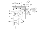
- FIG. 1 is a schematic view showing one embodiment of a film manufacturing apparatus according to the present invention.
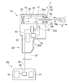
- FIG. 2 is a schematic view showing another embodiment of the film production apparatus according to the present invention.
- a polymer fiber formed from a liquefied polymer injected from an injection machine moves in a cavity and passes through a ring-shaped electrode provided in the cavity to form a cavity. Released outside. Due to the movement of the polymer fiber in the cavity, the polymer fiber tends to adhere to the inner wall of the cavity, and in some cases, the inside of the cavity may be clogged with the polymer fiber. As a result, it is not easy to form a target film successfully with the technique described in the document.
- the present invention relates to an improvement in an apparatus for forming a film using an electrostatic spray method.
- the present invention relates to an apparatus for directly applying a liquid composition containing a fiber-forming polymer to a surface of an object to form a coating made of a deposit containing fibers on the surface.
- an electrostatic spraying method is employed as a method for forming a coating.
- the electrostatic spray method is a method in which a positive or negative high voltage is applied to a liquid composition to charge the composition, and the charged composition is ejected toward an object.
- the electrostatic spraying method using the ejection of the liquid composition performed by the apparatus of the present invention is also an electrospinning method.
- the object for forming a film by the electrostatic spray method can be formed by being in close contact with the surface of an uneven object such as human skin or a plant surface such as a wall, tableware, a branch or a leaf.
- the irregularities include those that can be visually confirmed and those that are difficult to visually recognize, such as skin crevices.
- the coating is porous and has a suitable moisture transpiration property close to that of the human stratum corneum, it is preferable that the target is human skin, and it is preferable that the body is the target.
- FIG. 1 shows an embodiment of a film production apparatus according to the present invention.
- the apparatus 1 shown in FIG. 1 includes an electrostatic spray unit P1 as an electrospinning apparatus having a housing 10.
- a low-voltage power supply 11 is provided in the housing 10.
- the low-voltage power supply 11 can generate a voltage of several volts to several tens of volts.
- the low-voltage power supply 11 includes one or two or more batteries. Further, by using a battery as the low-voltage power supply 11, there is an advantage that replacement can be easily performed as necessary.
- An AC adapter or the like can be used as the low-voltage power supply 11 instead of the battery.
- a high-voltage power supply 12 is also provided in the housing 10 of the device 1.
- the high-voltage power supply 12 is electrically connected to the low-voltage power supply 11 and includes an electric circuit (not shown) that boosts a voltage generated by the low-voltage power supply 11 to a high voltage.
- the boosting electric circuit generally includes a transformer, a capacitor, a semiconductor element, and the like.
- An auxiliary electric circuit 13 is further provided in the housing 10 of the device 1.
- the auxiliary electric circuit 13 is interposed between the low-voltage power supply 11 and the high-voltage power supply 12 described above, and has a function of adjusting the voltage of the low-voltage power supply 11 and operating the high-voltage power supply 12 stably.
- the auxiliary electric circuit 13 has a function of controlling the number of rotations of a motor provided in the micro gear pump 14 described later. By controlling the number of rotations of the motor, the supply amount of the liquid composition to the microgear pump 14 from the liquid composition container 15 described later is controlled.
- a switch SW is mounted between the auxiliary electric circuit 13 and the low-voltage power supply 11, and the device 1 can be operated / stopped by turning the switch SW on and off.
- a nozzle 16 is further provided in the housing 10 of the device 1.
- the nozzle 16 is made of a non-conductive material such as plastic, rubber, and ceramic, and has a shape capable of discharging the liquid composition from the tip.
- a minute space through which the liquid composition flows is formed in the nozzle 16 along the longitudinal direction of the nozzle 16.
- the size of the cross section of the minute space is preferably 100 ⁇ m or more and 1000 ⁇ m or less in terms of diameter.
- the nozzle 16 communicates with the micro gear pump 14 via a pipe 17.
- the conduit 17 is generally made of a non-conductive material.
- the conduit 17 communicates the liquid composition container 15 with the nozzle 16 via the microgear pump 14.
- An electrode 20 is provided in the flow space of the liquid composition provided in the nozzle 16.
- the electrode 20 applies a voltage to the liquid composition passing through the nozzle 16 to charge the liquid composition.
- the electrode 20 is formed of a linear body extending along the flowing direction of the liquid composition.
- the electrode 20 can have a wire-like or needle-like shape.
- the thickness of the electrode 20 is such that it does not prevent the liquid composition from flowing through the nozzle 16.
- S1 cross-sectional area of the flow space of the liquid composition provided in the nozzle 16
- S2 is preferably 0.05% or more and 2% or less of S1.
- the length of the electrode 20 is not critical in the present invention, and may be any length as long as sufficient charge can be applied to the liquid composition flowing through the nozzle 16.
- the electrode 20 is made of a conductor such as a metal. Electrode 20 is electrically connected to high voltage power supply 12. This makes it possible to apply a high voltage to the electrode 20. In this case, the electrode 20 and the high-voltage power supply 12 are electrically connected via the current limiting resistor 19 in order to prevent an excessive current from flowing when the human body directly touches the electrode 20.
- the microgear pump 14 communicating with the nozzle 16 via the pipe 17 functions as a supply device for supplying the nozzle 16 with the liquid composition contained in the container 15.
- the micro gear pump 14 operates by receiving power supply from the low voltage power supply 11.
- the micro gear pump 14 is configured to supply a predetermined amount of the liquid composition to the nozzle 16 under the control of the auxiliary electric circuit 13.
- the housing 15 is connected to the micro gear pump 14 via a pipe 18.
- the liquid composition is stored in the storage section 15. It is preferable that the accommodating portion 15 has a cartridge type replaceable form.
- the housing 10 of the device 1 is also provided with an airflow generation unit 21.
- the air flow generating unit 21 is located behind the nozzle 16 with respect to the direction of discharging the liquid composition (the direction indicated by the symbol X in FIG. 1).
- the airflow generating section 21 takes in outside air into the housing 10 and generates an airflow along the discharge direction X of the liquid composition.
- the airflow generating section 21 is composed of, for example, a fan or a blower.
- the airflow generation unit 21 operates by receiving supply of electricity from the low-voltage power supply 11.
- a cavity 22 is located between the nozzle 16 and the airflow generating section 21.
- the cavity 22 is adjacent to the airflow generation unit 21.
- the cavity 22 is also adjacent to the nozzle 16. That is, it is preferable that no member extending between the hollow portion 22 and the airflow generating portion 21 extends in a direction orthogonal to the direction of the airflow and separates the hollow portion 22. Similarly, it is preferable that no member for partitioning the cavity 22 is interposed between the cavity 22 and the nozzle 16.
- the cavity 22 is preferably a single space formed of a cylindrical body 25 having both ends opened.
- the above-described airflow generating unit 21 is located at one open end of the tubular body 25.
- the air ejection part 23 is located at the other open end of the cylindrical body 25.
- the hollow portion 22 has a function of temporarily accumulating the airflow generated in the airflow generation portion 21.
- the cavity 22 has a sufficiently large volume with respect to the flow rate of the airflow generated in the airflow generation unit 21. It is ideal that the inside of the cylindrical body 25 is completely a space in terms of enhancing the temporary accumulation action of the air flow by the hollow portion 22.
- any member is not hollow. 22 may be present. In the embodiment shown in FIG. 1, a part of the nozzle 16, a part of the conduit 17, and a part of a circuit for applying a voltage to the electrode 20 are present in the cavity 22.
- the device 1 has a single cavity 22.
- a plurality of cavities formed by arranging a plurality of spaces partitioned by a partition member (not shown) in parallel in the liquid composition discharge direction X are employed. You can also.
- a plurality of cavities formed by arranging a plurality of spaces partitioned by a partition member (not shown) in series along the discharge direction X of the liquid composition may be employed.
- the partition member is provided in parallel with the air flow from the viewpoint of reducing pressure loss by rectifying the air flow and increasing the air flow. Is preferred.
- the air ejection portion 23 located at the open end of the cylindrical body 25 is a portion that ejects the air flow that has passed through the hollow portion 22 in the ejection direction X of the liquid composition.
- the air ejection part 23 includes a short flow path 23a including one or two or more through holes extending along the direction of the air flow.
- the air flow is jetted through an air jet port 24 which is an open end of the short flow path 23a.
- the short flow path 23a constituting the air ejection part 23 has a constant cross-sectional area.
- the air ejection port 24 is configured such that the direction of the air flow ejected from the air ejection port 24 is directed to the ejection direction of the liquid composition ejected from the nozzle 16.
- the air outlet 24 is located around the nozzle 16.
- the through holes are evenly arranged around the nozzle 16 from the viewpoint of stable air flow ejection.
- the air ejection part 23 (short flow path 23a) and the hollow part 22 are adjacent to each other, and no member is interposed between the two.
- a pipe connecting the hollow portion 22 and the air ejection portion 23 (short flow path 23a) is not interposed between them.
- the device 1 has a shape such that the flow velocity of the airflow flowing through the cavity 22 is increased by the principle of the orifice.
- the air outlet 24 located at the end of the cylindrical body 25 defining the cavity 22 has an opening area smaller than the cross-sectional area of the cavity 22. is there. This area can be referred to as the "throttle" of the airflow.
- the housing 10 constituting the device 1 is configured so that a person can grasp it by hand. Specifically, it is preferable that the housing 10 has a size and / or shape that can be gripped by one hand by a human from the viewpoint of improving operability.
- the casing 10 In order for the casing 10 to be “a dimension that can be held by one hand”, for example, the mass of the device 1 is 2 kg or less, or the maximum length of the casing 10 along the discharge direction X of the liquid composition is 40 cm or less. Alternatively, the volume of the housing 10 is preferably 3000 cm 3 or less.
- the casing 10 In order for the casing 10 to have a “shape that can be held by one hand”, for example, as shown in FIG. 1, it is preferable that the casing 10 has a handle 26 that can be held by a person with one hand. In particular, when the switch 26 for operating the device 1 is provided on the handle 26, the operability is further improved, which is advantageous.
- the user grips the device 1 with his hand and turns the tip 16a of the nozzle 16 toward the application site where electrostatic spraying is to be performed.
- the switch of the device 1 is turned on to perform the electrostatic spraying method.
- an electric field is generated between the electrode 20 and the application site.
- the application site becomes the negative electrode.
- an electric field is generated between the electrode 20 and the application site, the liquid composition in the form of droplets discharged from the tip 16a of the nozzle 16 flies in the space toward the application site along the electric field.
- the volatile solvent (which will be described later) evaporates from the liquid composition flying in the charged space, the charge density on the surface of the liquid composition becomes excessive, and the fiber-forming polymer becomes finer due to Coulomb repulsion. It spreads in space while repeating the process and reaches the application site. In this case, by appropriately adjusting the viscosity of the liquid composition, the ejected composition can reach the application site in the form of droplets.
- the volatile substance as the solvent is volatilized from the droplets, and while the fiber-forming polymer as the solute is solidified, the fiber is formed while being elongated and deformed by the potential difference, and the fiber is formed. It can also be deposited at the application site.
- the viscosity of the liquid composition tends to deposit the composition in the form of fibers at the application site.
- the porous coating made of fiber deposits can also be formed by adjusting the distance between the nozzle 16 and the application site and the voltage applied to the nozzle 16.
- the liquid composition when the liquid composition is discharged from the nozzle 16, an air flow is generated in the air flow generation unit 21, and the liquid composition is transported by the air flow.
- This makes it less likely to be affected by the surrounding environment in which the device 1 is used when forming the coating, and a uniform coating can be formed regardless of the surrounding environment. In particular, it is possible to form a uniform film regardless of changes in humidity.
- the electrostatic spray portion P1 is When viewed along the discharge direction X of the liquid composition, the tip 16a of the nozzle 16 is located at the extreme end of the electrostatic spray unit P1, so that the liquid composition discharged from the tip 16a flies. There are no blocking members. As a result, according to the apparatus 1 of the present embodiment, even when the liquid composition is conveyed in an air stream and flies, a target film can be successfully formed.
- the hollow portion 22 has a sufficient function of temporarily accumulating the airflow generated in the airflow generation portion 21.
- the value of V / F (min) which is the ratio of the volume V (cm 3 ) to the flow rate F (cm 3 / min) of the air flow generated in the air flow generation unit 21 is 0.001 min. It is preferably at least 0.002 min, more preferably at least 0.005 min. Further, the value of V / F (min) is preferably 0.5 min or less, more preferably 0.2 min or less, and even more preferably 0.1 min or less. Particularly, the value of V / F (min) is preferably from 0.001 min to 0.5 min, more preferably from 0.002 min to 0.2 min, and more preferably from 0.005 min to 0.1 min. Is more preferred.
- the value of the volume V itself of the cavity 22 is preferably, 20 cm 3 or more 500 cm 3 or less is 10 cm 3 or more 1000 cm 3 or less but more preferably, it is more preferably 30 cm 3 or more 100 cm 3 or less.
- the value of the flow rate F itself airflow is below 100 cm 3 / min or more 50000 cm 3 / min, further preferably 250 cm 3 / min or more 30000cm 3 / min or less, 500 cm 3 / min or more 20000cm More preferably, it is 3 / min or less.
- the volume V of the hollow portion 22 is equal to the volume of the internal space of the cylindrical body 25 that defines the hollow portion 22, and the hollow portion 22 has another member. Is a value obtained by subtracting the volume of the member from the volume of the internal space of the cylindrical body 25.
- the nozzle 16 has a liquid composition flow path through which the liquid composition reaches the tip 16 a of the nozzle 16 via the electrode 20.
- the casing 10 forming a part of the device 1 has a conduit 17 including the liquid composition flow path.
- the conduit 17 is disposed in the cavity 22 as shown in FIG.
- other members do not exist as much as possible in the internal space of the cylindrical body 25 defining the hollow portion 22. It is desirable. From this viewpoint, it is advantageous that the outer periphery of the pipe 17 is surrounded by the space of the hollow portion 22 and the hollow portion 22 is located behind the pipe 17.
- the direction of the air flow generated in the air flow generation section 21 (this direction is the same as the discharge direction X of the liquid composition)
- the cross-sectional area of the outer edge of the hollow portion 22 in a direction orthogonal to i.e., the cross-sectional area of the inner wall of the cylindrical body 25
- Q2 / Q1 which is a ratio of the average (Q2) of the cross-sectional area at a position other than the position to the cross-sectional area (Q1) of the outer edge of the hollow portion 22 at a position adjacent to the airflow generating portion 21.
- the outer edge of the hollow portion 22 means the outer edge of the space forming the hollow portion 22, and the area of the cross section of the outer edge is, for example, a case where a connecting portion such as a tube or a power supply cord is provided partially. Is calculated from the cross section of the outer edge of the cavity excluding these.
- the airflow generating unit 21 is, for example, a region where the fan is provided, and the position of the hollow portion 22 at a position adjacent to the airflow generating unit 21 is the position of the cylindrical portion adjacent to the region where the fan is provided. It shall be the fan side end.
- the average value (Q3) of the cross-sectional area of the airflow generation section 21 in a direction orthogonal to the direction of the airflow generation section 21 includes a fan and the like, so that the cavity 22 at a position adjacent to the airflow generation section 21 is included. It is preferable that the value is slightly larger than or equal to the area (Q1) of the cross section of the outer edge of the cross section.
- the value of the ratio Q3 / Q1 of the cross sectional area is preferably 80% or more, and more preferably 90% or more. Is more preferably 170% or less, more preferably 150% or less.
- the length of the air jet port 24 along the direction of the air flow is preferably 10 mm or less, more preferably 8 mm or less, and even more preferably 6 mm or less.
- the lower limit of the length is not particularly limited, but may be, for example, preferably 0.1 mm or more, and more preferably 0.5 mm or more.
- it is shorter than about 2 mm the air flow can be spouted from the air spout 24 sufficiently and smoothly.
- the above-mentioned cross-sectional area (Q1) of the outer edge of the hollow portion 22 at a position adjacent to the air flow generation portion 21 is referred to.
- the ratio of the sum of the areas of the air outlets 24 (hereinafter, this ratio is also referred to as “outlet area ratio”) is preferably 1.5% or more, more preferably 3% or more, and more preferably 5% or more. % Is more preferable.
- the area ratio of the ejection port is preferably 70% or less, more preferably 50% or less, and even more preferably 30% or less.
- the ejection opening area ratio is preferably from 1.5% to 70%, more preferably from 3% to 50%, even more preferably from 5% to 30%. .
- ejection amount of air flow from the air ejection port 24 is preferably 100 cm 3 / min or more, more preferably 250 cm 3 / min or more, is configured more preferably is adjusted to more than 500 cm 3 / min ing.
- the device 1 is preferably ejected amount of airflow 50000 cm 3 / min or less, more preferably 30000cm 3 / min or less, and is adapted to be adjusted in the following more preferably 20000 cm 3 / min.
- ejection amount of air flow from the air ejection port 24 is preferably 100 cm 3 / min or more 50000 cm 3 / min or less, more preferably 250 cm 3 / min or more 30000cm 3 / min or less, more preferably 500 cm 3 / Min to 20000 cm 3 / min.
- This value is the ejection amount of the air flow ejected from the air ejection port 24 when only one air ejection port 24 is provided, and is a value when a plurality of air ejection ports 24 are provided.
- the device 1 determines that the ejection amount of the liquid composition ejected from the nozzle 16 is:
- the pressure is adjusted to 0.01 g / min or more, more preferably 0.05 g / min or more, and still more preferably 0.1 g / min or more.
- the discharge rate of the liquid composition is preferably 2 g / min or less, more preferably 1.5 g / min or less, more preferably 1.0 g / min or less, and even more preferably 0.8 g / min or less. It is configured to be adjusted to.
- the apparatus 1 has a discharge rate of the liquid composition of preferably 0.01 g / min to 2 g / min, more preferably 0.05 g / min to 1.5 g / min, and still more preferably 0.1 g / min. It is configured to be adjusted to at least 1.0 g / min, more preferably at least 0.1 g / min and at most 0.8 g / min.
- the device 1 preferably applies a voltage of 1 kV or more, more preferably 5 kV or more, and more preferably 5 kV or more to the liquid composition when discharging the liquid composition from the nozzle 16.
- a voltage of 1 kV or more is configured to be adjusted to 10 kV or more.
- the device 1 is configured so that the voltage is adjusted to preferably 40 kV or less, more preferably 30 kV or less, more preferably 25 kV or less, and still more preferably 20 kV or less.
- the voltage applied to the liquid composition is preferably adjusted to 1 kV or more and 40 kV or less, more preferably 5 kV or more and 30 kV or less, more preferably 10 kV or more and 25 kV or less, and still more preferably 10 kV or more and 20 kV or less. Is configured.
- FIG. 2 shows another embodiment of the film production apparatus of the present invention.
- the same members as those in FIG. 1 are denoted by the same reference numerals.
- the apparatus 1 of the embodiment shown in FIG. 2 is roughly divided into an electrostatic spray section P1 and a stationary storage section P2. Both are separate.
- the electrostatic spray unit P1 is the device 1 itself, but in the present embodiment, among the members constituting the electrostatic spray unit P1 of the embodiment shown in FIG.
- the electrostatic spraying section P1 and the stationary storage section P2 are connected by a conduit 18 for sending the liquid composition and an electric wire 27 for electrically connecting the electrode 20 to the low-voltage power supply 11.
- the electrostatic spray part P1 has a size and / or shape that can be gripped by one hand by a human. According to the present embodiment, the liquid composition can be discharged for a long time without impairing the ease of handling of the electrostatic spray portion P1, and a large-area film can be easily formed.
- the conduit 18 and the electric wire 27 for connecting the electrostatic spray part P1 and the stationary storage part P2 are independent of each other, but taking into account the handling of the electrostatic spray part P1.
- the conduit 18 and the electric wire 27 may be bundled into one cable.
- the liquid composition containing the fiber-forming polymer is directly applied to the surface of the object while ejecting an air flow from the air ejection port by using the apparatus for producing a film according to each of the embodiments described above.
- a coating composed of a deposit containing fibers can be formed on the surface.
- the liquid composition used in each of the above-described embodiments contains a polymer having a fiber-forming property. Further, the liquid composition preferably contains one or more volatile substances selected from water, alcohol and ketone.
- a volatile substance is a substance that has volatility in a liquid state.
- the volatile substance in the liquid composition is discharged from the tip 16a of the nozzle 16 toward the skin after sufficiently charging the liquid composition placed in the electric field, and the volatile substance evaporates, The charge density of the composition becomes excessive, and the volatile substances further evaporate while the polymer becomes finer due to Coulomb repulsion, and are finally blended to form fibers.
- the volatile substance has a vapor pressure of preferably from 0.01 kPa to 106.66 kPa at 20 ° C., more preferably from 0.13 kPa to 66.66 kPa, more preferably from 0.13 kPa to 66.66 kPa.
- the pressure is more preferably 67 kPa or more and 40.00 kPa or less, even more preferably 1.33 kPa or more and 40.00 kPa or less.
- the alcohol is preferably, for example, a monovalent chain aliphatic alcohol having 1 to 6 carbon atoms, a monovalent cyclic aliphatic alcohol having 3 to 6 carbon atoms, or a monovalent aromatic alcohol.
- a monovalent chain aliphatic alcohol having 1 to 6 carbon atoms a monovalent cyclic aliphatic alcohol having 3 to 6 carbon atoms
- a monovalent aromatic alcohol used for Specific examples thereof include ethanol, isopropyl alcohol, butyl alcohol, phenylethyl alcohol, propanol, and pentanol.
- ethanol isopropyl alcohol
- butyl alcohol phenylethyl alcohol
- propanol propanol
- pentanol pentanol.
- One or more of these alcohols can be used.
- ketone for example, a chain aliphatic ketone having 3 to 6 carbon atoms, a cyclic aliphatic ketone having 3 to 6 carbon atoms, or an aromatic ketone having 8 to 10 carbon atoms is preferably used.
- Specific examples thereof include acetone, methyl ethyl ketone, methyl isobutyl ketone, cyclohexanone, acetophenone and the like. These ketones can be used alone or in combination of two or more.
- ion-exchanged water purified water or distilled water is preferably used as water.
- the conductivity of the liquid composition can be increased due to ionization of the water. Due to the high conductivity of the liquid composition, a fibrous film can be stably formed on the surface of the application site such as the skin when electrostatic spraying is performed. Water also contributes to improving the adhesion of the coating formed by the electrostatic spray to skin and the like.
- the volatile substance is more preferably one or more selected from ethanol, isopropyl alcohol, butyl alcohol, and water, and more preferably one or more selected from water, ethanol, and butyl alcohol. And more preferably water and ethanol.
- the volatile substance is (a) one or more selected from ethanol, isopropyl alcohol, and butyl alcohol from the viewpoint of dispersibility of the fiber-forming polymer used together with the volatile substance and from the viewpoint of imparting electric charge.
- (B) a mixture with water.
- the value of (b) / (a), which is the mass ratio between (a) and (b), is preferably 0.0025 or more and 1 or less from the viewpoints of fiber formability and film adhesion. It is preferable that it is 0025 or more and 0.85 or less.
- the value of (b) / (a), which is the mass ratio between the component (a) and the component (b), depends on the fiber forming property and the coating film. It is preferably 0.0025 or more and 0.3 or less, more preferably 0.0025 or more and 0.2 or less from the viewpoint of adhesion.
- the content of water in the liquid composition is preferably from 0.2% by mass to 45% by mass, and more preferably from 0.3% by mass to 40% by mass from the viewpoint of further improving the fiber-forming property and the adhesion of the film. It is more preferred that:
- the content of water in the liquid composition is preferably from 0.2% by mass to 25% by mass, more preferably from 0.3% by mass to 20% by mass.
- the content is more preferably not more than 0.35% by mass and not more than 19% by mass, more preferably not less than 0.4% by mass and not more than 18% by mass.
- the fiber-forming polymer used with the volatile substance is generally a substance that can be dissolved in the volatile substance.
- the term “dissolve” means that it is in a dispersed state at 20 ° C., and the dispersed state is a visually uniform state, preferably a transparent or translucent state.
- the fiber-forming polymer As the fiber-forming polymer, an appropriate one is used depending on the nature of the volatile substance. Specifically, the fiber-forming polymer is roughly classified into a water-soluble polymer and a water-insoluble polymer.
- water-soluble polymer refers to a polymer weighed at 1 g in an environment of 1 atm and 23 ° C., immersed in 10 g of ion-exchanged water, and after 24 hours, the polymer immersed in 0. A substance having a property of dissolving 5 g or more in water.
- water-insoluble polymer refers to a polymer weighed at 1 g under an environment of 1 atm and 23 ° C., then immersed in 10 g of ion-exchanged water, and after 24 hours, the immersion of the polymer A substance having a property of not dissolving more than 0.5 g.
- water-soluble fiber-forming polymer examples include mucopolysaccharides such as pullulan, hyaluronic acid, chondroitin sulfate, poly- ⁇ -glutamic acid, modified corn starch, ⁇ -glucan, gluco-oligosaccharide, heparin, kerato sulfate, cellulose, pectin, xylan , Chitosan, lignin, glucomannan, galacturonic acid, psyllium seed gum, tamarind seed gum, gum arabic, tragacanth, soy-soluble polysaccharide, alginic acid, carrageenan, laminaran, agar (agarose), fucoidan, methylcellulose, hydroxypropylcellulose, hydroxypropyl Natural polymers such as methylcellulose, partially saponified polyvinyl alcohol (when not used with a crosslinking agent), low-saponified polyvinyl alcohol, polyvinylpyrrolidone (
- water-soluble polymers can be used alone or in combination of two or more.
- these water-soluble polymers from the viewpoint of easy production of a coating film, pullulan, partially saponified polyvinyl alcohol, low-saponified polyvinyl alcohol, polyvinylpyrrolidone, chitosan, a water-soluble polyamide resin, a water-soluble polyurethane resin, polyethylene oxide, etc. It is preferable to use a synthetic polymer of When polyethylene oxide is used as the water-soluble polymer, the number average molecular weight is preferably 50,000 or more and 3,000,000 or less, more preferably 100,000 or more and 2.5 million or less.
- examples of the water-insoluble fiber-forming polymer include, for example, fully saponified polyvinyl alcohol which can be insolubilized after forming the fiber, partially saponified polyvinyl alcohol which can be cross-linked after forming the fiber by using in combination with a crosslinking agent, and poly (N-propanoylethylene).
- Oxazoline-modified silicone such as graft-dimethylsiloxane / ⁇ -aminopropylmethylsiloxane copolymer, polyvinyl acetal diethylaminoacetate, twain (major component of corn protein), polyester, polylactic acid (PLA), polyacrylonitrile resin, polymethacrylic Acrylic resin such as acid resin, polystyrene resin, polyvinyl butyral resin, polyethylene terephthalate resin, polybutylene terephthalate resin, polyurethane resin, polyamide resin, poly Bromide resins, and polyamide-imide resins.
- PVA polylactic acid
- PMMA polyacrylonitrile resin
- polymethacrylic Acrylic resin such as acid resin, polystyrene resin, polyvinyl butyral resin, polyethylene terephthalate resin, polybutylene terephthalate resin, polyurethane resin, polyamide resin, poly Bromide resins, and polyamide-imide
- water-insoluble polymers completely saponified polyvinyl alcohol that can be insolubilized after fiber formation, partially saponified polyvinyl alcohol that can be cross-linked after fiber formation by using in combination with a crosslinking agent, polyvinyl butyral resin, polymethacrylic acid resin, polyvinyl acetal diethylaminoacetate
- oxazoline-modified silicone such as poly (N-propanoylethyleneimine) -graft-dimethylsiloxane / ⁇ -aminopropylmethylsiloxane copolymer, polyurethane resin, polyamide resin, polylactic acid, twain and the like.
- the content of the volatile substance in the liquid composition is preferably from 50% by mass to 95% by mass, more preferably from 55% by mass to 94% by mass, and more preferably from 60% by mass to 93% by mass. More preferably, it is more preferably 65% by mass or more and 92% by mass or less.
- the content of the fiber-forming polymer in the liquid composition is preferably from 2% by mass to 35% by mass, more preferably from 3% by mass to 30% by mass, and more preferably from 5% by mass to 25% by mass. % Is more preferable.
- the thickness of the fibers is preferably 10 nm or more, more preferably 50 nm or more, as represented by a circle equivalent diameter. It is preferably at most 3,000 nm, more preferably at most 1,000 nm.
- the thickness of the fiber can be measured by, for example, observing the fiber at a magnification of 10000 by scanning electron microscope (SEM) observation, removing defects (lumps of fiber, intersections of fibers, droplets) from the two-dimensional image, It can be measured by arbitrarily selecting ten fibers, drawing a line perpendicular to the longitudinal direction of the fibers, and directly reading the fiber diameter.
- the fibers are continuous fibers of infinite length in the principle of production, but preferably have a length of at least 100 times the thickness of the fibers.
- a fiber having a length of 100 times or more the thickness of the fiber is defined as "continuous fiber”.
- the coating produced by the apparatus 1 of the present embodiment is preferably a porous discontinuous coating composed of a deposit of continuous fibers. Such a coating film not only can be handled as a single sheet as an aggregate, but also has very soft characteristics, and is unlikely to be separated even when a shearing force is applied thereto.
- the distance between the nozzle 16 and the application site depends on the voltage applied to the nozzle 16, but from the viewpoint of forming the film successfully, the distance is 10 mm or more. Is preferably 20 mm or more, more preferably 40 mm or more, and even more preferably 60 mm or more. Further, the distance between the nozzle 16 and the application site is preferably 300 mm or less, more preferably 250 mm or less, further preferably 200 mm or less, and even more preferably 150 mm or less.
- the distance between the nozzle 16 and the application site is preferably from 10 mm to 300 mm, more preferably from 20 mm to 250 mm, even more preferably from 40 mm to 200 mm, More preferably, it is 60 mm or more and 150 mm or less.
- the distance between the nozzle and the application site can be measured by a generally used non-contact sensor or the like.
- the basis weight of the coating is 0.05 g / m 2 or more in terms of 1 m 2 of skin.
- it is 0.1 g / m 2 or more, more preferably 1 g / m 2 or more.
- it is preferably 50 g / m 2 or less, more preferably 40 g / m 2 or less, further preferably 30 g / m 2 or less, further preferably 25 g / m 2 or less, and more preferably 20 g / m 2 or less. It is even more preferred that the value be m 2 or less.
- the basis weight of the coating in terms of per skin 1 m 2 is preferably 0.05 g / m 2 or more 50 g / m 2 or less, more not less 0.1 g / m 2 or more 40 g / m 2 or less It is more preferably 0.1 g / m 2 or more and 30 g / m 2 or less, further preferably 0.1 g / m 2 or more and 25 g / m 2 or less, and more preferably 1 g / m 2 or more and 20 g / m 2 or less. Is more preferable.
- peeling of the coating due to excessive thickness of the coating can be effectively prevented.
- the electrostatic spray unit P1 is of a handy type.
- the electrostatic spray unit P1 may be of a large stationary type.
- Example 1 (1) Preparation of liquid composition A liquid composition containing 88% of 99.5% ethanol (0.5% of water) and 12% of polyvinyl butyral was prepared. As polyvinyl butyral, S-LEC B BM-1 (trade name) manufactured by Sekisui Chemical Co., Ltd. was used. (2) Preparation of Coating Manufacturing Apparatus An apparatus having the configuration shown in FIG. 1 was prepared. The volume of the cavity 22 was 72 cm 3 (a value obtained by subtracting the volume of the conduit 17), and the flow rate of the air flow generated in the air flow generation unit 21 was 750 cm 3 / min.
- the cylindrical body 25 constituting the hollow portion 22 was cylindrical, had a diameter of 32 mm, and a cross-sectional area Q1 was 8.04 cm 2 .
- the cross-sectional area Q2 described above was 7.1 cm 2 (average diameter 30 mm), and Q3 was 11.3 cm 2 .
- Eight circular air outlets 24 were provided, and the length of 23a along the direction of the air flow was set to 6 mm. The above-described outlet area ratio was 6.2%.
- (3) Formation of Coating Film Consisting of Fiber Deposits The ejection amount of the liquid composition from nozzle 16 was set to 0.12 g / min, and the ejection amount of air from air ejection port 24 was set to 750 cm 3 / min.
- the voltage applied to the electrode 20 was set to 10 kV.
- a coating made of fiber deposits was formed on one surface of the collecting plate made of polyoxymethylene by electrospinning.
- the distance between the tip 16a of the nozzle 16 and the collecting plate was set to 100 mm.
- the surrounding environment when performing the electrospinning method was 30 ° C. and 70% RH.
- Example 2 to 4 and Comparative Examples 1 and 2 The amount of air ejected from the air outlet 24 and the surrounding environment were set to the values shown in Table 1 below. Except for these, a coating consisting of fiber deposits was formed in the same manner as in Example 1.
- a uniform film can be easily formed even under an environment where it is not easy to control the environment to a constant temperature and a constant humidity.
Landscapes
- Engineering & Computer Science (AREA)
- Textile Engineering (AREA)
- Mechanical Engineering (AREA)
- Electrostatic Spraying Apparatus (AREA)
- Application Of Or Painting With Fluid Materials (AREA)
- Nonwoven Fabrics (AREA)
- Spinning Methods And Devices For Manufacturing Artificial Fibers (AREA)
Priority Applications (3)
| Application Number | Priority Date | Filing Date | Title |
|---|---|---|---|
| EP19869486.1A EP3862468A1 (en) | 2018-10-03 | 2019-10-03 | Coating production device |
| CN201980055334.XA CN112601848A (zh) | 2018-10-03 | 2019-10-03 | 覆膜的制造装置 |
| US17/268,797 US20210178412A1 (en) | 2018-10-03 | 2019-10-03 | Coating production device |
Applications Claiming Priority (2)
| Application Number | Priority Date | Filing Date | Title |
|---|---|---|---|
| JP2018-188681 | 2018-10-03 | ||
| JP2018188681 | 2018-10-03 |
Publications (1)
| Publication Number | Publication Date |
|---|---|
| WO2020071474A1 true WO2020071474A1 (ja) | 2020-04-09 |
Family
ID=70055242
Family Applications (1)
| Application Number | Title | Priority Date | Filing Date |
|---|---|---|---|
| PCT/JP2019/039078 Ceased WO2020071474A1 (ja) | 2018-10-03 | 2019-10-03 | 被膜の製造装置 |
Country Status (5)
| Country | Link |
|---|---|
| US (1) | US20210178412A1 (enExample) |
| EP (1) | EP3862468A1 (enExample) |
| JP (1) | JP6882409B2 (enExample) |
| CN (1) | CN112601848A (enExample) |
| WO (1) | WO2020071474A1 (enExample) |
Families Citing this family (4)
| Publication number | Priority date | Publication date | Assignee | Title |
|---|---|---|---|---|
| JP6967567B2 (ja) * | 2018-10-17 | 2021-11-17 | 花王株式会社 | 静電紡糸装置 |
| CN111992346A (zh) * | 2020-09-18 | 2020-11-27 | 士商(上海)机械有限公司 | 喷雾器 |
| WO2023021070A1 (en) * | 2021-08-19 | 2023-02-23 | Swansea University | Fluid ionising device |
| CN113699688A (zh) * | 2021-10-15 | 2021-11-26 | 杭州俊为科技有限责任公司 | 一种手持式的纳米薄膜的制备设备 |
Citations (6)
| Publication number | Priority date | Publication date | Assignee | Title |
|---|---|---|---|---|
| JP2004525272A (ja) | 2001-03-20 | 2004-08-19 | ナイキャスト リミテッド | 携帯式電気紡糸装置 |
| JP2015052193A (ja) * | 2013-08-08 | 2015-03-19 | 花王株式会社 | ナノファイバ製造装置、ナノファイバの製造方法及びナノファイバ成型体 |
| CN204738056U (zh) * | 2015-04-29 | 2015-11-04 | 青岛新智源健康科技有限公司 | 一种便携式静电纺丝设备 |
| US20160287227A1 (en) * | 2015-04-01 | 2016-10-06 | Covidien Lp | Electrospinning device and method for applying polymer to tissue |
| CN206457563U (zh) * | 2017-01-18 | 2017-09-01 | 青岛中科凯尔科技有限公司 | 一种新型便携式静电纺丝装置 |
| CN108251897A (zh) * | 2018-03-16 | 2018-07-06 | 北京化工大学 | 一种手持式熔体静电纺丝制备装置及使用方法 |
Family Cites Families (4)
| Publication number | Priority date | Publication date | Assignee | Title |
|---|---|---|---|---|
| US6514504B1 (en) * | 1999-08-18 | 2003-02-04 | The Procter & Gamble Company | Discontinuous films from skin care compositions |
| KR100707845B1 (ko) * | 2004-09-27 | 2007-04-13 | 마츠시다 덴코 가부시키가이샤 | 정전무화 헤어드라이어 |
| JP5027554B2 (ja) * | 2007-04-27 | 2012-09-19 | 公立大学法人首都大学東京 | 1軸または多軸配向ナノファイバー集積体の製造方法及び製造装置 |
| WO2009113290A1 (en) * | 2008-03-12 | 2009-09-17 | Panasonic Corporation | Fiber manufacturing method, fiber manufacturing apparatus and proton-exchange membrane fuel cell |
-
2019
- 2019-10-02 JP JP2019182543A patent/JP6882409B2/ja active Active
- 2019-10-03 WO PCT/JP2019/039078 patent/WO2020071474A1/ja not_active Ceased
- 2019-10-03 US US17/268,797 patent/US20210178412A1/en not_active Abandoned
- 2019-10-03 CN CN201980055334.XA patent/CN112601848A/zh not_active Withdrawn
- 2019-10-03 EP EP19869486.1A patent/EP3862468A1/en not_active Withdrawn
Patent Citations (6)
| Publication number | Priority date | Publication date | Assignee | Title |
|---|---|---|---|---|
| JP2004525272A (ja) | 2001-03-20 | 2004-08-19 | ナイキャスト リミテッド | 携帯式電気紡糸装置 |
| JP2015052193A (ja) * | 2013-08-08 | 2015-03-19 | 花王株式会社 | ナノファイバ製造装置、ナノファイバの製造方法及びナノファイバ成型体 |
| US20160287227A1 (en) * | 2015-04-01 | 2016-10-06 | Covidien Lp | Electrospinning device and method for applying polymer to tissue |
| CN204738056U (zh) * | 2015-04-29 | 2015-11-04 | 青岛新智源健康科技有限公司 | 一种便携式静电纺丝设备 |
| CN206457563U (zh) * | 2017-01-18 | 2017-09-01 | 青岛中科凯尔科技有限公司 | 一种新型便携式静电纺丝装置 |
| CN108251897A (zh) * | 2018-03-16 | 2018-07-06 | 北京化工大学 | 一种手持式熔体静电纺丝制备装置及使用方法 |
Also Published As
| Publication number | Publication date |
|---|---|
| JP6882409B2 (ja) | 2021-06-02 |
| JP2020056147A (ja) | 2020-04-09 |
| EP3862468A1 (en) | 2021-08-11 |
| US20210178412A1 (en) | 2021-06-17 |
| CN112601848A (zh) | 2021-04-02 |
Similar Documents
| Publication | Publication Date | Title |
|---|---|---|
| JP6882409B2 (ja) | 被膜の製造装置 | |
| CN103069057B (zh) | 用于静电驱动溶剂喷射或颗粒形成的设备、方法以及流体组合物 | |
| CN105431577B (zh) | 纳米纤维制造装置、纳米纤维的制造方法和纳米纤维成型体 | |
| CN1096301C (zh) | 喷洒装置 | |
| CN111356796A (zh) | 电纺丝装置及其系统和方法 | |
| AU2004220079A1 (en) | Apparatuses and methods for electrostatically processing polymer formulations | |
| HK1044126A1 (zh) | 鼻吸器 | |
| WO2004074172A1 (ja) | 固定化方法、固定化装置および微小構造体製造方法 | |
| US20220033994A1 (en) | Methods and systems for electrospinning using low power voltage converter | |
| JP2020056147A5 (enExample) | ||
| WO2014118584A1 (en) | Delivering electrically charged liquids | |
| JP6967567B2 (ja) | 静電紡糸装置 | |
| JP6782872B1 (ja) | 静電スプレー装置、カートリッジおよびカバー | |
| JP2004074015A (ja) | 塗布装置および塗布方法 | |
| JP6967034B2 (ja) | 静電噴出装置 | |
| JP7303228B2 (ja) | 静電紡糸装置 | |
| JP2014117691A (ja) | 成膜装置 | |
| JP2023173495A (ja) | 静電噴出装置 | |
| JP2020195957A (ja) | 静電噴出装置 | |
| JP6315691B2 (ja) | 電界紡糸装置の評価方法 | |
| WO2023021070A1 (en) | Fluid ionising device | |
| WO2014189375A1 (en) | Method for depositing a coating material on a medical device and medical device | |
| JPS5829149B2 (ja) | 粉体塗布用静電噴霧装置 |
Legal Events
| Date | Code | Title | Description |
|---|---|---|---|
| 121 | Ep: the epo has been informed by wipo that ep was designated in this application |
Ref document number: 19869486 Country of ref document: EP Kind code of ref document: A1 |
|
| NENP | Non-entry into the national phase |
Ref country code: DE |
|
| ENP | Entry into the national phase |
Ref document number: 2019869486 Country of ref document: EP Effective date: 20210503 |