WO2020071243A1 - 電子機器、電子機器の制御方法、及び電子機器の制御プログラム - Google Patents
電子機器、電子機器の制御方法、及び電子機器の制御プログラムInfo
- Publication number
- WO2020071243A1 WO2020071243A1 PCT/JP2019/037919 JP2019037919W WO2020071243A1 WO 2020071243 A1 WO2020071243 A1 WO 2020071243A1 JP 2019037919 W JP2019037919 W JP 2019037919W WO 2020071243 A1 WO2020071243 A1 WO 2020071243A1
- Authority
- WO
- WIPO (PCT)
- Prior art keywords
- transmission
- wave
- electronic device
- frequency
- control unit
- Prior art date
Links
- 238000000034 method Methods 0.000 title claims description 24
- 230000005540 biological transmission Effects 0.000 claims abstract description 376
- 238000001514 detection method Methods 0.000 description 91
- 238000010586 diagram Methods 0.000 description 20
- 230000007274 generation of a signal involved in cell-cell signaling Effects 0.000 description 20
- 238000012545 processing Methods 0.000 description 18
- 238000005516 engineering process Methods 0.000 description 10
- 238000006243 chemical reaction Methods 0.000 description 9
- 230000008569 process Effects 0.000 description 8
- 230000006870 function Effects 0.000 description 7
- 230000008859 change Effects 0.000 description 5
- 238000004891 communication Methods 0.000 description 4
- 230000003111 delayed effect Effects 0.000 description 4
- 238000012986 modification Methods 0.000 description 4
- 230000004048 modification Effects 0.000 description 4
- 230000003247 decreasing effect Effects 0.000 description 3
- 238000005259 measurement Methods 0.000 description 3
- 238000001228 spectrum Methods 0.000 description 3
- 241001465754 Metazoa Species 0.000 description 2
- 239000000463 material Substances 0.000 description 2
- 230000005855 radiation Effects 0.000 description 2
- 238000010408 sweeping Methods 0.000 description 2
- 229920003051 synthetic elastomer Polymers 0.000 description 2
- 229920003002 synthetic resin Polymers 0.000 description 2
- 239000000057 synthetic resin Substances 0.000 description 2
- 239000005061 synthetic rubber Substances 0.000 description 2
- 238000012935 Averaging Methods 0.000 description 1
- 108010076504 Protein Sorting Signals Proteins 0.000 description 1
- 230000003321 amplification Effects 0.000 description 1
- 230000006835 compression Effects 0.000 description 1
- 238000007906 compression Methods 0.000 description 1
- 230000007423 decrease Effects 0.000 description 1
- 230000002542 deteriorative effect Effects 0.000 description 1
- 238000011161 development Methods 0.000 description 1
- 238000003384 imaging method Methods 0.000 description 1
- 230000006872 improvement Effects 0.000 description 1
- 238000009434 installation Methods 0.000 description 1
- 230000007257 malfunction Effects 0.000 description 1
- 238000003199 nucleic acid amplification method Methods 0.000 description 1
- 239000004065 semiconductor Substances 0.000 description 1
Images


Classifications
-
- G—PHYSICS
- G01—MEASURING; TESTING
- G01S—RADIO DIRECTION-FINDING; RADIO NAVIGATION; DETERMINING DISTANCE OR VELOCITY BY USE OF RADIO WAVES; LOCATING OR PRESENCE-DETECTING BY USE OF THE REFLECTION OR RERADIATION OF RADIO WAVES; ANALOGOUS ARRANGEMENTS USING OTHER WAVES
- G01S13/00—Systems using the reflection or reradiation of radio waves, e.g. radar systems; Analogous systems using reflection or reradiation of waves whose nature or wavelength is irrelevant or unspecified
- G01S13/02—Systems using reflection of radio waves, e.g. primary radar systems; Analogous systems
- G01S13/06—Systems determining position data of a target
- G01S13/08—Systems for measuring distance only
- G01S13/32—Systems for measuring distance only using transmission of continuous waves, whether amplitude-, frequency-, or phase-modulated, or unmodulated
- G01S13/34—Systems for measuring distance only using transmission of continuous waves, whether amplitude-, frequency-, or phase-modulated, or unmodulated using transmission of continuous, frequency-modulated waves while heterodyning the received signal, or a signal derived therefrom, with a locally-generated signal related to the contemporaneously transmitted signal
- G01S13/347—Systems for measuring distance only using transmission of continuous waves, whether amplitude-, frequency-, or phase-modulated, or unmodulated using transmission of continuous, frequency-modulated waves while heterodyning the received signal, or a signal derived therefrom, with a locally-generated signal related to the contemporaneously transmitted signal using more than one modulation frequency
-
- G—PHYSICS
- G01—MEASURING; TESTING
- G01S—RADIO DIRECTION-FINDING; RADIO NAVIGATION; DETERMINING DISTANCE OR VELOCITY BY USE OF RADIO WAVES; LOCATING OR PRESENCE-DETECTING BY USE OF THE REFLECTION OR RERADIATION OF RADIO WAVES; ANALOGOUS ARRANGEMENTS USING OTHER WAVES
- G01S13/00—Systems using the reflection or reradiation of radio waves, e.g. radar systems; Analogous systems using reflection or reradiation of waves whose nature or wavelength is irrelevant or unspecified
- G01S13/02—Systems using reflection of radio waves, e.g. primary radar systems; Analogous systems
- G01S13/06—Systems determining position data of a target
- G01S13/42—Simultaneous measurement of distance and other co-ordinates
-
- G—PHYSICS
- G01—MEASURING; TESTING
- G01S—RADIO DIRECTION-FINDING; RADIO NAVIGATION; DETERMINING DISTANCE OR VELOCITY BY USE OF RADIO WAVES; LOCATING OR PRESENCE-DETECTING BY USE OF THE REFLECTION OR RERADIATION OF RADIO WAVES; ANALOGOUS ARRANGEMENTS USING OTHER WAVES
- G01S13/00—Systems using the reflection or reradiation of radio waves, e.g. radar systems; Analogous systems using reflection or reradiation of waves whose nature or wavelength is irrelevant or unspecified
- G01S13/88—Radar or analogous systems specially adapted for specific applications
- G01S13/93—Radar or analogous systems specially adapted for specific applications for anti-collision purposes
- G01S13/931—Radar or analogous systems specially adapted for specific applications for anti-collision purposes of land vehicles
-
- G—PHYSICS
- G01—MEASURING; TESTING
- G01S—RADIO DIRECTION-FINDING; RADIO NAVIGATION; DETERMINING DISTANCE OR VELOCITY BY USE OF RADIO WAVES; LOCATING OR PRESENCE-DETECTING BY USE OF THE REFLECTION OR RERADIATION OF RADIO WAVES; ANALOGOUS ARRANGEMENTS USING OTHER WAVES
- G01S7/00—Details of systems according to groups G01S13/00, G01S15/00, G01S17/00
- G01S7/02—Details of systems according to groups G01S13/00, G01S15/00, G01S17/00 of systems according to group G01S13/00
- G01S7/40—Means for monitoring or calibrating
-
- G—PHYSICS
- G01—MEASURING; TESTING
- G01S—RADIO DIRECTION-FINDING; RADIO NAVIGATION; DETERMINING DISTANCE OR VELOCITY BY USE OF RADIO WAVES; LOCATING OR PRESENCE-DETECTING BY USE OF THE REFLECTION OR RERADIATION OF RADIO WAVES; ANALOGOUS ARRANGEMENTS USING OTHER WAVES
- G01S13/00—Systems using the reflection or reradiation of radio waves, e.g. radar systems; Analogous systems using reflection or reradiation of waves whose nature or wavelength is irrelevant or unspecified
- G01S13/02—Systems using reflection of radio waves, e.g. primary radar systems; Analogous systems
- G01S2013/0236—Special technical features
- G01S2013/0245—Radar with phased array antenna
Definitions
- the present disclosure relates to an electronic device, a control method for the electronic device, and a control program for the electronic device.
- a technique of measuring a distance between a host vehicle and a predetermined object is regarded as important.
- a radar that measures the distance to an object by transmitting a radio wave such as a millimeter wave and receiving a reflected wave reflected by an object such as an obstacle (RADAR (Radio Detecting and Ranging))
- RADAR Radio Detecting and Ranging
- a plurality of transmitting antennas for transmitting a transmitting wave A plurality of receiving antennas for receiving the reflected wave of the transmitted wave, A control unit that detects an object that reflects the transmission wave based on a transmission signal transmitted as the transmission wave and a reception signal received as the reflection wave.
- the control unit determines a band portion for transmitting the transmission wave in a predetermined frequency band according to an incident angle when the reception antenna receives the reflected wave.
- a method for controlling an electronic device includes the following steps (1) to (3). (1) transmitting a transmitting wave from a plurality of transmitting antennas; (2) receiving a reflected wave reflecting the transmitting wave from a plurality of receiving antennas; and (3) a transmitting signal transmitted as the transmitting wave and the reflection. Detecting an object that reflects the transmission wave based on a reception signal received as a wave (4) changing the transmission wave to a predetermined frequency in accordance with an incident angle when the reception antenna receives the reflection wave; Determining the band portion to be transmitted in the band
- a control program for an electronic device causes a computer to execute the above steps (1) to (4).
- FIG. 9 is a diagram illustrating a usage mode of the electronic device according to the embodiment.
- FIG. 2 is a functional block diagram schematically illustrating a configuration of the electronic device according to the embodiment.
- FIG. 9 is a diagram illustrating an example of a reflected wave received by the electronic device according to one embodiment.
- FIG. 9 is a diagram illustrating an example of a reflected wave received by the electronic device according to one embodiment.
- FIG. 6 is a diagram illustrating an example of a frequency band of a transmission wave transmitted by the electronic device according to one embodiment.
- FIG. 5 is a diagram illustrating an operation of the electronic device according to the first embodiment.
- FIG. 5 is a diagram illustrating an operation of the electronic device according to the first embodiment.
- FIG. 6 is a flowchart illustrating an operation of the electronic device according to the first embodiment.
- FIG. 9 is a diagram illustrating an operation of the electronic device according to the second embodiment.
- FIG. 9 is a diagram illustrating an operation of the electronic device according to the second embodiment.
- 9 is a flowchart illustrating an operation of the electronic device according to the second embodiment.
- FIG. 14 is a diagram illustrating an operation of the electronic device according to the third embodiment.
- 9 is a flowchart illustrating an operation of the electronic device according to the third embodiment.
- beamforming for forming a beam of a transmission wave transmitted from a plurality of transmission antennas.
- beamforming by forming beams of transmission waves transmitted from a plurality of transmission antennas in a predetermined direction, for example, the reach of radio waves can be extended.
- measurement accuracy detection accuracy
- Patent Document 1 proposes that, when estimating the azimuth of an object using a receiving array antenna, erroneous estimation due to side ropes and grating lobes is suppressed.
- An object of the present disclosure is to provide an electronic device, a control method of the electronic device, and a control program of the electronic device that improve the detection accuracy of an object.
- the electronic device can be mounted on a vehicle (moving body) such as an automobile, for example, to detect a predetermined object existing around the moving body. For this reason, the electronic device according to one embodiment can transmit a transmission wave around the moving object from the transmitting antenna installed on the moving object. In addition, the electronic device according to one embodiment can receive a reflected wave in which a transmitted wave is reflected from a receiving antenna provided on a moving object. At least one of the transmitting antenna and the receiving antenna may be provided in, for example, a radar sensor or the like installed on a mobile object.
- the electronic device according to an embodiment is not limited to an automobile.
- the electronic device according to an embodiment may be mounted on various moving objects such as an autonomous vehicle, a bus, a truck, a motorcycle, a bicycle, a ship, an aircraft, a drone, a robot, and a pedestrian.
- the electronic device according to the embodiment is not necessarily limited to a mobile object that moves with its own power.
- the moving body on which the electronic device according to the embodiment is mounted may be a trailer portion towed by a tractor.
- the electronic device detects an object existing around the sensor unit in a situation where at least one of the sensor unit and the object can move, and measures a distance or the like between the sensor unit and the object. can do.
- the electronic device can measure a distance between the sensor unit and the object even when both the sensor unit and the object are stationary.
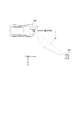
- FIG. 1 is a diagram illustrating a usage mode of an electronic device according to an embodiment.
- FIG. 1 illustrates an example in which a sensor including a transmitting antenna and a receiving antenna according to one embodiment is installed on a moving body.
- a sensor 5 including a transmission antenna and a reception antenna according to one embodiment is installed in the mobile object 100 shown in FIG.
- the sensor 5 may include, for example, at least one of a transmitting antenna and a receiving antenna. Further, the sensor 5 may appropriately include at least one of other functional units such as at least a part of the control unit 10 (FIG. 2) included in the electronic device 1.
- the moving body 100 shown in FIG. 1 may be an automobile such as a passenger car, but may be any type of moving body. In FIG. 1, the moving body 100 may be moving (running or slowing down) in the positive Y-axis direction (traveling direction), for example, may be moving in another direction, or may be moving. It may be stationary without it.
- a sensor 5 having a plurality of transmitting antennas and a plurality of receiving antennas is installed on the moving body 100.
- only one sensor 5 including a transmitting antenna and a receiving antenna is installed in front of the moving body 100.
- the position where the sensor 5 is installed on the moving body 100 is not limited to the position shown in FIG. 1, and may be another position as appropriate.
- the sensor 5 as shown in FIG. 1 may be installed on the left side, right side, and / or rear side of the moving body 100.
- the number of such sensors 5 may be one or more arbitrary numbers in accordance with various conditions (or requirements) such as the range and / or accuracy of the measurement in the moving body 100.
- the sensor 5 transmits an electromagnetic wave as a transmission wave from the transmission antenna. For example, when a predetermined object (for example, the object 200 shown in FIG. 1) exists around the moving body 100, at least a part of the transmission wave transmitted from the sensor 5 is reflected by the object and becomes a reflected wave. Then, by receiving such a reflected wave by, for example, the receiving antenna of the sensor 5, the electronic device 1 mounted on the moving body 100 can detect the object.
- a predetermined object for example, the object 200 shown in FIG. 1
- the electronic device 1 mounted on the moving body 100 can detect the object.
- the sensor 5 having a transmitting antenna may be a radar (RADAR (Radio Detecting and Ranging)) sensor that transmits and receives radio waves.
- RADAR Radio Detecting and Ranging
- the sensor 5 is not limited to a radar sensor.
- the sensor 5 according to an embodiment may be, for example, a sensor based on the technology of LIDAR (Light Detection and Ranging, Laser Imaging and Detection and Ranging) using light waves.
- LIDAR Light Detection and Ranging, Laser Imaging and Detection and Ranging
- Such sensors can be configured to include, for example, a patch antenna. Since techniques such as RADAR and LIDAR are already known, the detailed description may be simplified or omitted as appropriate.
- the electronic device 1 mounted on the mobile unit 100 shown in FIG. 1 receives a reflected wave of a transmission wave transmitted from the transmission antenna of the sensor 5 from the reception antenna. In this manner, the electronic device 1 can detect the predetermined object 200 existing within a predetermined distance from the moving body 100. For example, as shown in FIG. 1, the electronic device 1 can measure a distance L between a moving object 100 that is a host vehicle and a predetermined object 200. Further, the electronic device 1 can also measure the relative speed between the moving object 100 which is the host vehicle and the predetermined object 200. Further, the electronic device 1 can also measure the direction (the angle of arrival ⁇ ) at which the reflected wave from the predetermined object 200 arrives at the moving body 100 that is the host vehicle.
- the object 200 is, for example, at least one of an oncoming vehicle running in a lane adjacent to the moving body 100, a car running in parallel with the moving body 100, and a car before and after running in the same lane as the moving body 100.
- the object 200 may be any object existing around the moving object 100, such as a motorcycle, a bicycle, a stroller, a pedestrian, a guardrail, a median strip, a road sign, a step on a sidewalk, a wall, a manhole, and an obstacle.
- the object 200 may be moving or may be stopped.
- the object 200 may be a car parked or stopped around the moving body 100.
- the object 200 detected by the electronic device 1 includes not only inanimate objects but also living objects such as humans and animals.
- the object 200 detected by the electronic device 1 of the present disclosure includes a target including a person, an object, an animal, and the like, detected by the radar technology.
- the sensor 5 installed in front of the moving body 100 can form a beam of a transmission wave in front of the moving body 100 (beam forming), for example.
- the electronic device 1 controls the phase of each transmission wave so that the phases of the transmission waves transmitted from the plurality of transmission antennas are aligned in the forward direction (positive Y-axis direction) of the moving body 100.
- the plurality of transmission waves reinforce each other in the forward direction (positive Y-axis direction) of the moving body 100 to form a radio wave beam.
- accuracy such as measurement of a distance to a predetermined object detected by a transmission wave can be improved.
- the reach of the transmission wave can be extended.
- the electronic device 1 can change the direction of the beam of the transmission wave by appropriately controlling the phase of the transmission wave transmitted from the plurality of antennas.
- the electronic device 1 can direct the beam of the transmission wave transmitted from the transmission antenna 40 in various directions by appropriately changing the phase of the transmission wave.
- the electronic device 1 can also measure the direction (the angle of arrival ⁇ ) at which the reflected wave from the predetermined object 200 arrives at the moving body 100 that is the host vehicle. According to the beamforming, the radiation direction of the transmission wave can be controlled to improve the accuracy of measuring an angle with respect to a predetermined object.
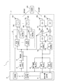
- FIG. 2 is a functional block diagram schematically showing a configuration example of the electronic device 1 according to one embodiment.
- the configuration of the electronic device 1 according to the embodiment will be described.
- the electronic device 1 includes a sensor 5 and a control unit 10.
- one sensor 5 is connected to one control unit 10.
- the control unit 10 and the sensors 5 can each have an arbitrary number.
- a plurality of sensors 5 may be connected to one control unit 10.
- only one sensor 5 is shown in more detail as a representative example of a plurality of sensors 5 that can be connected to the control unit 10.
- the electronic device 1 may include a signal generation unit 22, a frequency synthesizer 24, a transmission control unit 30, power amplifiers 36A and 36B, and transmission antennas 40A and 40B.
- the above-described sensor 5 may include at least the transmitting antennas 40A and 40B. Further, the sensor 5 may include other functional units such as the control unit 10, the transmission control unit 30, and / or the power amplifiers 36A and 36B. In the examples shown in FIGS. 1 and 2, the sensor 5 and the control unit 10 are shown as separate functional units, but the sensor 5 may include all or a part of the control unit 10. Further, the members included in the sensor 5 are not limited to the example illustrated in FIG. 2, and any member of the members illustrated in FIG.
- the transmitting antenna 40A and the transmitting antenna 40B, the receiving antenna 50A and the receiving antenna 50B, and the power amplifier 36A and the power amplifier 36B may be housed in one housing as the sensor 5.
- the transmitting antenna 40A and the transmitting antenna 40B, the receiving antenna 50A and the receiving antenna 50B, and the power amplifier 36A and the power amplifier 36B may be housed in one housing as the sensor 5.
- the number of transmitting antennas and receiving antennas can be any number.
- the electronic device 1 shown in FIG. 2 includes two transmission antennas 40A and 40B.
- transmission antenna 40 when the transmission antenna 40A and the transmission antenna 40B are not distinguished, they are simply referred to as “transmission antenna 40”.
- the electronic device 1 illustrated in FIG. 2 may include two other functional units (for example, power amplifiers 36A and 36B). Regarding such other functional units, when a plurality of functional units of the same type are not particularly distinguished, the functional units may be collectively referred to by omitting symbols such as A and B.
- the electronic device 1 includes receiving antennas 50A and 50B, LNAs 52A and 52B, mixers 54A and 54B, IF units 56A and 56B, AD converting units 58A and 58B, a distance estimating unit 62, an angle estimating unit 64, In addition, a relative speed estimation unit 66 may be provided.
- the functional units when a plurality of functional units of the same type are not particularly distinguished, the functional units may be collectively referred to by omitting symbols such as A and B.
- the above-described sensor 5 may include the receiving antennas 50A and 50B. Further, the sensor 5 may include other functional units such as the LNAs 52A and 52B.
- the control unit 10 included in the electronic device 1 can control the operation of the entire electronic device 1 including the control of each functional unit included in the electronic device 1.
- the control unit 10 may include at least one processor such as a CPU (Central Processing Unit) to provide control and processing capability for performing various functions.
- the control unit 10 may be realized by a single processor, may be realized by several processors, or may be realized by individual processors.
- the processor may be implemented as a single integrated circuit. An integrated circuit is also called an IC (Integrated Circuit).
- the processor may be implemented as a plurality of communicatively connected integrated circuits and discrete circuits.
- the processor may be implemented based on various other known technologies.
- the control unit 10 may be configured as, for example, a CPU and a program executed by the CPU.
- the control unit 10 may include a storage unit 12, a detection range determination unit 14, and a frequency selection unit 16.
- the detection range determination unit 14 and the frequency selection unit 16 may be configured as hardware having the function, or may be configured with, for example, a microcomputer, or may be executed by a processor such as a CPU and the processor. It may be configured as a program or the like.
- the storage unit 12 may store a program executed in the control unit 10, a result of a process executed in the control unit 10, and the like. Further, the storage unit 12 may function as a work memory of the control unit 10.
- the storage unit 12 can be composed of, for example, a semiconductor memory or a magnetic disk, but is not limited thereto, and can be an arbitrary storage device. Further, for example, the storage unit 12 may be a storage medium such as a memory card inserted into the electronic device 1 according to the present embodiment. Further, the storage unit 12 may be an internal memory of the CPU used as the control unit 10 as described above.
- the detection range determination unit 14 determines a range in which an object is detected based on the transmission wave T transmitted from the transmission antenna 40 and the reflected wave R received from the reception antenna 50. In one embodiment, the detection range determination unit 14 may determine the object detection range based on estimation by at least one of the distance estimation unit 62 and the angle estimation unit 64. The determination of the object detection range by the detection range determination unit 14 will be further described later. The detection range determination unit 14 may notify the frequency selection unit 16 of the determined object detection range.
- the frequency selection unit 16 determines the frequency of the transmission wave T transmitted from the transmission antenna 40. In one embodiment, the frequency selection unit 16 selects a predetermined band portion for transmitting the transmission wave T in a predetermined frequency band prepared as a frequency band usable for detection, for example. In one embodiment, the frequency selection unit 16 may select a predetermined band portion for transmitting the transmission wave T based on the detection range determined by the detection range determination unit 14. Such selection of the predetermined band portion by the frequency selection unit 16 will be further described later. The frequency selecting unit 16 may notify the selected frequency to the frequency synthesizer 24. In this case, the frequency synthesizer 24 can increase the frequency of the transmission wave T to the frequency of the predetermined frequency band selected by the frequency selection unit 16.
- the control unit 10 can control the transmission control unit 30.
- the control unit 10 may control the transmission control unit 30 based on various information stored in the storage unit 12. Further, in the electronic device 1 according to one embodiment, the control unit 10 may instruct the signal generation unit 22 to generate a signal, or control the signal generation unit 22 to generate a signal.
- the control unit 10 can obtain control information of the mobile unit 100 from an ECU (for example, the mobile unit control unit 70) or the like. Therefore, in the electronic device 1 according to the embodiment, the control unit 10 may determine the transmission mode of the transmission wave based on the obtained control information or the like.
- the transmission mode of the transmission wave may be, for example, one of an operation mode for performing beamforming (BF mode) and an operation mode for not performing beamforming (normal mode).
- the transmission mode of the transmission wave may be various settings in each mode described above.
- the transmission mode of the transmission wave may define the number of transmission antennas (the number of antennas) for transmitting the transmission wave in each of the above modes.
- the transmission mode of the transmission wave may define, for example, the presence or absence of beamforming and / or the angle of beamforming.
- the angle of beamforming may be an angle for increasing the beam gain with respect to the location (position) where the transmitting antenna 40 is installed in the moving body 100 when performing beamforming.
- the control unit 10 supplies the setting information in the transmission mode to the transmission control unit 30.
- the setting information in the transmission mode may include, for example, information on the number of transmission antennas that transmit transmission waves in the transmission mode.
- the setting information in the transmission mode may include, for example, information on the power at which the transmission antenna transmits a transmission wave in the transmission mode.
- the setting information in the transmission mode may include information on the phase of each transmission wave transmitted from the plurality of transmission antennas 40 when performing beamforming.
- information in which various transmission modes are associated with setting information necessary for the operation in the transmission mode may be stored in the storage unit 12 in advance as a table, for example.
- the phase information of the transmission wave when performing beamforming in a certain transmission mode is stored in the storage unit 12 in association with the location (position) where the transmission antenna 40 is installed in the mobile unit 100 and the installation angle. You may.
- the control unit 10 can read the setting information corresponding to the determined transmission mode from the storage unit 12 and supply the setting information to the transmission control unit 30.
- the transmission power of the transmission wave T may be adjusted to change the gain of the transmission antenna 40 and / or the beamforming gain.
- the transmission power of the transmission wave T transmitted by the transmission antenna 40 may be stored in the storage unit 12 in association with the gain of the transmission antenna 40 and / or the beamforming gain.
- the various transmission modes described above and the setting information corresponding to the transmission modes may be appropriately generated based on various conditions.
- the control unit 10 can supply the setting information to the transmission control unit 30 even if the setting information corresponding to the determined transmission mode is not stored in the storage unit 12. it can.
- the signal generation unit 22 generates a signal (transmission signal) transmitted as the transmission wave T from the transmission antenna 40 under the control of the control unit 10.
- the signal generation unit 22 allocates the frequency of the transmission signal based on, for example, control by the control unit 10.
- the signal generation unit 22 generates a signal of a predetermined frequency in a frequency band such as 77 to 81 GHz by receiving frequency information from the control unit 10.
- the signal generation unit 22 may include a functional unit such as a voltage controlled oscillator (VCO).
- VCO voltage controlled oscillator
- aGHz and bGHz mean aGHz or more and less than bGHz, where a and b are arbitrary numbers.
- aGHz and bGHz may be larger than aGHz and equal to or smaller than bGHz, where a and b are arbitrary numbers.
- the signal generation unit 22 may be configured as hardware having the function, may be configured as a microcomputer, for example, or may be configured as a processor such as a CPU and a program executed by the processor. Is also good.
- Each functional unit described below may be configured as hardware having the function, or, if possible, may be configured with, for example, a microcomputer, or may be configured with a processor such as a CPU and executed by the processor. It may be configured as a program to be executed.
- the signal generation unit 22 may generate a transmission signal such as a chirp signal.
- the signal generator 22 may generate a signal whose frequency periodically changes linearly (linear chirp signal).
- the signal generation unit 22 may be a chirp signal whose frequency periodically and linearly increases from 77 GHz to 81 GHz over time.
- the signal generation unit 22 may generate a signal whose frequency periodically repeats linearly increasing (up-chirp) and decreasing (down-chirp) from 77 GHz to 81 GHz over time.
- the signal generated by the signal generation unit 22 may be set in the control unit 10 in advance, for example.
- the signal generated by the signal generation unit 22 may be stored in the storage unit 12 in advance, for example. Since a chirp signal used in a technical field such as radar is known, a more detailed description will be simplified or omitted as appropriate.
- the signal generated by the signal generator 22 is supplied to the frequency synthesizer 24.
- the frequency synthesizer 24 raises the frequency of the signal generated by the signal generator 22 to a frequency in a predetermined frequency band.
- the frequency synthesizer 24 may increase the frequency of the signal generated by the signal generation unit 22 to the frequency selected as the frequency of the transmission wave T transmitted from the transmission antenna 40.
- the frequency selected as the frequency of the transmission wave T transmitted from the transmission antenna 40 may be set by, for example, the control unit 10.
- the frequency synthesizer 24 may increase the frequency of the signal generated by the signal generator 22 to the frequency selected by the frequency selector 16.
- the frequency selected as the frequency of the transmission wave T transmitted from the transmission antenna 40 may be stored in the storage unit 12, for example.
- the signal whose frequency has been increased by the frequency synthesizer 24 is supplied to the transmission control unit 30 and the mixer 54.
- the transmission control unit 30 performs control for transmitting a transmission signal supplied from the frequency synthesizer 24 as a transmission wave T from at least one of the plurality of transmission antennas 40.
- the transmission control unit 30 may include a phase control unit 32 and a power control unit 34. Further, as illustrated in FIG. 2, the transmission control unit 30 may perform control for transmitting a transmission wave T from the transmission antenna 40 based on the control by the control unit 10.
- Various information necessary for the control unit 10 to control the transmission control unit 30 may be stored in the storage unit 12.
- the phase control unit 32 controls the phase of the transmission signal supplied from the frequency synthesizer 24. Specifically, the phase control unit 32 may adjust the phase of the transmission signal by appropriately advancing or delaying the phase of the signal supplied from the frequency synthesizer 24 based on the control of the control unit 10. In this case, the phase control unit 32 may adjust the phase of each transmission signal based on the path difference between the transmission waves T transmitted from the plurality of transmission antennas 40. By appropriately adjusting the phase of each transmission signal by the phase control unit 32, the transmission waves T transmitted from the plurality of transmission antennas 40 reinforce each other in a predetermined direction to form a beam (beam forming).
- the phase control unit 32 when transmitting the transmission wave T without performing beamforming in the normal mode, the phase control unit 32 does not need to control the phase of the transmission signal transmitted as the transmission wave T from the transmission antenna 40. Further, for example, when performing beamforming of the transmission wave T in the BF mode, the phase control unit 32 sets the phases of a plurality of transmission signals transmitted as the transmission wave T from the plurality of transmission antennas 40 according to the direction of the beamforming. Each may be controlled. In this case, the correlation between the direction of beamforming and the amount of phase to be controlled of the transmission signal transmitted by each of the plurality of transmission antennas 40 may be stored in the storage unit 12, for example. The signal whose phase has been controlled by the phase control unit 32 is supplied to the power amplifier 36.
- the power control units 34 are connected to the corresponding power amplifiers 36, as shown in FIG.
- the power control unit 34 controls power amplification by a power amplifier 36 connected to the power control unit 34.
- the power control unit 34 controls the transmission power of the transmission wave T transmitted from the transmission antenna 40 connected to the power amplifier 36 by controlling the power amplifier 36.
- the power control unit 34 can switch on and off the transmission power of the power amplifier 36 connected to the power control unit 34. That is, the power control unit 34 can switch whether to transmit the transmission wave T from the transmission antenna 40 connected to the power amplifier 36.
- the power control unit 34A can switch on and off the transmission power of the transmission wave T transmitted from the transmission antenna 40A.
- the power control unit 34B can switch on and off the transmission power of the transmission wave T transmitted from the transmission antenna 40B. Therefore, the electronic device 1 determines whether the transmission wave T is transmitted from the transmission antenna 40A and / or the transmission antenna 40B based on the control of both the power control unit 34A and the power control unit 34B. It can be arbitrarily controlled. Further, the power control unit 34 may appropriately adjust the transmission power of the power amplifier 36 connected to the power control unit 34. As described above, the power control unit 34 can specify how many transmission antennas 40 out of the plurality of transmission antennas 40 transmit the transmission wave T based on the setting in the transmission mode, for example.
- the storage unit 12 may store a correlation between the control by the power control unit 34 and the transmission power of the transmission wave T transmitted from the corresponding transmission antenna 40. Further, the storage unit 12 may store the above-described correlation for various transmission modes.
- the electronic device 1 transmits the transmission wave T transmitted from at least one of the plurality of transmission antennas 40 based on the control of the phase control unit 32 and / or the power control unit 34 in the transmission control unit 30.
- the electronic device 1 according to one embodiment can set variously whether or not to perform beamforming and / or the direction of a beam when performing beamforming.
- the storage unit 12 may store control information of the phase control unit 32 and / or the power control unit 34 corresponding to various transmission modes of the transmission wave T.
- the control unit 10 can control the transmission wave T by the phase control unit 32 and / or the power control unit 34 by reading control information corresponding to various transmission modes of the transmission wave T from the storage unit 12.
- the power control unit 34 controls the power for transmitting the transmission wave T according to the antenna radiation gain of each transmission antenna 40. Control. Further, for example, when the electronic device 1 operates in the above-described BF mode (performs beam forming), the phase control unit 32 appropriately changes the phase of the transmission signal transmitted from the transmission antenna used among the plurality of transmission antennas 40. . In one embodiment, when performing beam forming of the transmission wave T transmitted from the plurality of transmission antennas 40, the number of beams and / or the shape of the beams are determined based on the control by the phase control unit 32 and the power control unit 34. , Various types.
- the power amplifier 36 amplifies the power of the transmission signal supplied from the phase control unit 32 based on the control by the power control unit 34. Since the technology itself for amplifying the power of the transmission signal is already known, a more detailed description will be omitted.
- the power amplifier 36 is connected to the transmission antenna 40.
- the transmission antenna 40 outputs (transmits) the transmission signal amplified by the power amplifier 36 as a transmission wave T.
- the sensor 5 may be configured to include a plurality of transmission antennas, for example, the transmission antenna 40A and the transmission antenna 40B. Since the transmitting antenna 40 can be configured in the same manner as a transmitting antenna used for a known radar technology, a more detailed description is omitted.
- the electronic device 1 can transmit a transmission signal such as a chirp signal as the transmission wave T from the plurality of transmission antennas 40, for example.
- a transmission signal such as a chirp signal
- at least one of the functional units constituting the electronic device 1 may be housed in a housing having a structure that cannot be easily opened in one housing.
- the transmission antenna 40A and the transmission antenna 40B, the reception antenna 50A and the reception antenna 50B, and the power amplifier 36A and the power amplifier 36B are housed in one housing, and the housing cannot be easily opened. Good.
- the transmitting antenna 40 may transmit the transmission wave T to the outside of the moving body 100 via a member such as a radar cover.
- the radar cover may be made of a material that allows electromagnetic waves to pass, such as a synthetic resin or rubber.
- This radar cover may be, for example, a housing for the sensor 5.
- a member such as a radar cover
- the radar cover and the housing may also be referred to as a radome (the same applies hereinafter).
- the electronic device 1 illustrated in FIG. 2 includes two transmission antennas 40, such as the transmission antenna 40A and the transmission antenna 40B, and transmits the transmission wave T by the two transmission antennas 40. Therefore, the electronic device 1 illustrated in FIG. 2 includes two functional units required for transmitting the transmission wave T from the two transmission antennas 40, respectively.
- the transmission control unit 30 includes two phase control units 32 like the phase control unit 32A and the phase control unit 32B. Further, the transmission control unit 30 includes two power control units 34 like a power control unit 34A and a power control unit 34B. Further, the electronic device 1 shown in FIG. 2 includes two power amplifiers 36 like a power amplifier 36A and a power amplifier 36B.
- the number of the transmission antennas 40 included in the electronic device 1 according to an embodiment may be an arbitrary number such as three or more.
- the electronic device 1 according to one embodiment may include the same number of power amplifiers 36 as the plurality of transmission antennas 40.
- the electronic device 1 according to one embodiment may include the same number of phase control units 32 and power control units 34 as the plurality of transmission antennas 40.
- the receiving antenna 50 receives the reflected wave R.
- the reflected wave R is obtained by reflecting the transmitted wave T on a predetermined object 200.
- the receiving antenna 50 may be configured to include a plurality of antennas, for example, the receiving antenna 50A and the receiving antenna 50B.
- the receiving antenna 50 can be configured in the same manner as a receiving antenna used for a known radar technology, and thus a more detailed description is omitted.
- the receiving antenna 50 is connected to the LNA 52. A reception signal based on the reflected wave R received by the reception antenna 50 is supplied to the LNA 52.
- the electronic device 1 can receive, from a plurality of receiving antennas 50, a reflected wave R in which a transmission wave T transmitted as a transmission signal such as a chirp signal is reflected by a predetermined object 200.
- at least one functional unit constituting the electronic device 1 such as the plurality of receiving antennas 50 may be housed in a housing having a structure that cannot be easily opened in one housing.
- the receiving antenna 50 may receive the reflected wave R from outside the moving body 100 via a member such as a radar cover.
- the radar cover may be made of a material that allows electromagnetic waves to pass, such as a synthetic resin or rubber. This radar cover may be, for example, a housing for the sensor 5.
- the sensor 5 may include, for example, all the transmitting antennas 40 and all the receiving antennas 50. Furthermore, when the receiving antenna 50 is installed near the transmitting antenna 40, these may be collectively included in one sensor 5. That is, one sensor 5 may include, for example, at least one transmitting antenna 40 and at least one receiving antenna 50. For example, one sensor 5 may include a plurality of transmitting antennas 40 and a plurality of receiving antennas 50. In such a case, for example, one radar sensor may be covered with a member such as one radar cover.
- the LNA 52 amplifies a reception signal based on the reflected wave R received by the reception antenna 50 with low noise.
- the LNA 52 may be a low noise amplifier (Low Noise Amplifier), and amplifies the reception signal supplied from the reception antenna 50 with low noise.
- the received signal amplified by the LNA 52 is supplied to the mixer 54.
- the mixer 54 generates a beat signal by mixing (multiplying) the reception signal of the RF frequency supplied from the LNA 52 with the transmission signal supplied from the frequency synthesizer 24.
- the beat signal mixed by the mixer 54 is supplied to the IF unit 56.
- the IF unit 56 converts the frequency of the beat signal supplied from the mixer 54 to an intermediate frequency (IF (Intermediate Frequency)) by performing frequency conversion on the beat signal supplied from the mixer 54.
- IF Intermediate Frequency
- the AD conversion unit 58 digitizes the analog beat signal supplied from the IF unit 56.
- the AD converter 58 may be configured by an arbitrary analog-to-digital converter (Analog to Digital Converter (ADC)).
- ADC Analog to Digital Converter
- the beat signal digitized by the AD converter 58 is supplied to the distance estimating unit 62 when the number of the receiving antennas 50 is one, and to both the distance estimating unit 62 and the angle estimating unit 64 when the number of the receiving antennas 50 is plural. .
- the distance estimation unit 62 estimates the distance between the moving object 100 on which the electronic device 1 is mounted and the object 200 based on the beat signal supplied from the AD conversion unit 58.
- the distance estimation unit 62 may include, for example, an FFT processing unit.
- the FFT processing unit may be configured by an arbitrary circuit or chip that performs a fast Fourier transform (Fast Fourier Transform (FFT)) process.
- FFT Fast Fourier Transform
- the FFT processing unit performs an FFT process on the beat signal digitized by the AD conversion unit 58.
- the distance estimating unit 62 may perform an FFT process on the complex signal supplied from the AD converting unit 58.
- the distance estimating unit 62 may determine that the predetermined object 200 is located at a distance corresponding to the peak. Information on the distance estimated by the distance estimating unit 62 may be supplied to, for example, the control unit 10.
- the angle estimating unit 64 determines the direction from the moving body 100 on which the electronic device 1 is mounted to the object 200 (that is, the direction in which the reflected wave R arrives at the receiving antenna 50).
- the angle estimating unit 64 may include, for example, an FFT processing unit, similarly to the distance estimating unit 62.
- the distance estimation unit 62 performs the FFT processing on the complex signal supplied from the AD conversion unit 58, and when the peak obtained as a result of the FFT processing is equal to or more than a predetermined threshold, the distance corresponding to the peak. May be determined that there is a predetermined object 200.
- the angle estimating unit 64 determines the direction in which the reflected wave R arrives at the receiving antenna 50 (that is, the direction from the object 200 to the receiving antenna (The direction toward 50).
- the direction in which the reflected wave R arrives at the receiving antenna 50 which is estimated by the angle estimating unit 64, may be the direction from the object 200 to the receiving antenna 50.
- Information on the direction (arrival direction or angle of arrival) estimated by the angle estimating unit 64 may be supplied to, for example, the control unit 10.
- the relative speed estimating unit 66 estimates the relative speed between the object 200 and the moving body 100 based on the beat signal.
- a frequency spectrum can be obtained by performing FFT processing on a beat signal.
- the above-described FFT processing unit can estimate whether or not the predetermined object 200 exists within the range of the beam of the transmission wave T transmitted from the transmission antenna 40. That is, the FFT processing unit can estimate whether or not the predetermined object 200 exists within the range of the beam emitted by the sensor 5 including the transmitting antenna 40 based on the beat signal subjected to the FFT processing. Further, the FFT processing section can also estimate the distance between the sensor 5 including the transmitting antenna 40 and the object 200 based on the beat signal subjected to the FFT processing when the predetermined object 200 is present.
- the FFT processing unit can also estimate the positional relationship between the sensor 5 including the transmitting antenna 40 and the object 200 based on the beat signal subjected to the FFT processing when the predetermined object 200 exists.
- the distance estimating unit 62, the angle estimating unit 64, and the relative speed estimating unit 66 may perform a Fourier transform other than the fast Fourier transform (Fast @ Fourier @ Transform (FFT)).
- the electronic device 1 performs the communication between the object 200 and the moving body 100 based on the signal transmitted as the transmission wave T and the beat signal obtained from the signal received as the reflection wave R. May be measured (estimated). Further, the electronic device 1 according to one embodiment measures (estimates) the positional relationship between the object 200 and the moving object 100 (for example, the angle of arrival at which the reflected wave R arrives at the moving object 100 from the object 200) based on the beat signal. ). Furthermore, the electronic device 1 according to an embodiment may measure (estimate) the relative speed between the object 200 and the moving body 100 based on the beat signal.
- control unit 10 performs various calculations, estimations, controls, and the like based on information on the distance supplied from the distance estimation unit 62 and / or information on the direction (angle) supplied from the angle estimation unit 64.
- a technology for estimating a distance and / or a direction to a predetermined object reflected by a reflected wave based on a beat signal acquired using a millimeter wave radar such as a 79 GHz band is known. A more detailed description is omitted.
- the electronic device 1 shown in FIG. 2 includes two receiving antennas 50 like the receiving antenna 50A and the receiving antenna 50B, and receives the reflected wave R by the two receiving antennas 50. Therefore, the electronic device 1 shown in FIG. 2 includes two functional units required to receive the reflected waves R from the two receiving antennas 50, respectively. Specifically, the electronic device 1 includes two LNAs 52, two mixers 54, two IF units 56, and two AD conversion units 58.
- the electronic device 1 illustrated in FIG. 2 includes the two receiving antennas 50.
- the number of the receiving antennas 50 included in the electronic device 1 according to an embodiment may be an arbitrary number.
- the electronic device 1 according to an embodiment may include the same number of functional units as the plurality of receiving antennas 50, each including the two functional units described above.
- FMCW radar Frequency Modulated Continuous Wave
- the FMCW radar generates a transmission signal by sweeping the frequency of a radio wave to be transmitted. Therefore, for example, in a millimeter-wave FMCW radar that uses radio waves in a frequency band of 79 GHz, the frequency of the radio waves used has a frequency bandwidth of 4 GHz, such as 77 GHz to 81 GHz.
- the radar of the 79 GHz frequency band is characterized in that the usable frequency bandwidth is wider than other millimeter / quasi-millimeter wave radars such as the 24 GHz, 60 GHz, and 76 GHz frequency bands.
- the transmission signal transmitted by the electronic device 1 of the present disclosure may be a chirp signal.
- the chirp signal is a signal whose frequency continuously changes with time.
- the chirp signal is also called a frequency modulated continuous wave (FMCW (Frequency Modulated Continuous Wave)).
- the change in the frequency of the chirp signal may be increasing or decreasing, or a combination of increasing and decreasing.
- the chirp signal may include a linear chirp signal whose frequency changes linearly with time, an exponential chirp signal whose frequency changes exponentially with time, and the like.
- the signal generated by the signal generation unit 22 is not limited to the FMCW signal.
- the signal generated by the signal generation unit 22 may be a signal of various systems such as a pulse system, a pulse compression system (spread spectrum system), or a frequency CW (Continuous Wave) system.
- a frequency-modulated continuous wave radar hereinafter, referred to as FMCW radar (Frequency Modulated Continuous Waveave radar)
- FMCW radar Frequency Modulated Continuous Waveave radar
- the frequency of the radio waves used has a frequency bandwidth of 4 GHz, such as 77 GHz to 81 GHz.
- the radar of the 79 GHz frequency band is characterized in that the usable frequency bandwidth is wider than other millimeter / quasi-millimeter wave radars such as the 24 GHz, 60 GHz, and 76 GHz frequency bands.
- the FMCW radar system used in the present disclosure may include an FCM system (Fast-Chirp Modulation) that transmits a chirp signal at a shorter cycle than usual.
- the signal generated by the signal generation unit 22 is not limited to the FM-CW signal.
- the signal generated by the signal generation unit 22 may be a signal of various systems other than the FM-CW system.
- the transmission signal sequence stored in the storage unit 12 may be different depending on these various methods. For example, in the case of the above-mentioned FM-CW radar signal, a signal whose frequency increases and a signal whose frequency decreases for each time sample may be used.
- Known techniques can be applied to the various methods described above as appropriate, and thus a more detailed description is omitted.
- the electronic device 1 by forming (beamforming) the beams of the radio waves transmitted from the plurality of transmission antennas 40, the transmission waves in a predetermined direction can be strengthened. In this way, the electronic device 1 can improve the accuracy of measuring the distance between the moving object 100 on which the electronic device 1 is mounted and the object 200 and / or the direction of the object 200. Therefore, the electronic device 1 according to one embodiment performs beam forming as necessary with such a transmission wave while using a radio wave whose frequency changes with time as a transmission wave like an FMCW radar.
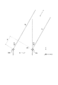
- FIG. 3 is a diagram illustrating an example of a reception wave received by the electronic device 1.
- two reception antennas 50A and 50B are arranged as the plurality of reception antennas 50 as shown in FIG.
- an arbitrary plurality of receiving antennas 50 may be arranged.
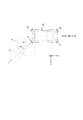
- the electronic device 1 can estimate (measure) the direction of an object by including a plurality of receiving antennas 50 as shown in FIG. Specifically, the electronic device 1 according to one embodiment receives the reflected wave R, which is a reflection of the transmission wave T transmitted from the transmission antenna 40 by an object, by a plurality of reception antennas 50. Then, the electronic device 1 according to one embodiment estimates the direction of the object reflecting the transmission wave T based on the path difference D between the plurality of reflected waves R received by the plurality of receiving antennas 50.
- a direction (Y-axis direction) perpendicular to the direction in which the plurality of receiving antennas 50 are arranged (X-axis direction) is defined as a reference direction.
- the angle between the straight line parallel to the above-described reference direction (Y-axis direction) and the straight line corresponding to the direction in which the reflected wave R is incident on the receiving antenna 50 is defined as an angle of incidence. Angle ⁇ .
- the receiving antenna 50A and the receiving antenna 50B are arranged at a distance W from each other.
- a description will be given assuming that a plurality of receiving antennas 50 arranged as described above receive radio waves (reflected waves R) from the direction ⁇ (incident angle 30 °) shown in FIG. That is, a case will be described below where the receiving antenna 50A and the receiving antenna 50B receive the reflected wave R traveling in the direction ⁇ from the right side by 30 ° with respect to the positive direction of the Y axis.
- the interval W between the receiving antenna 50A and the receiving antenna 50B shown in FIG. 3 is ⁇ / 2, where ⁇ is the wavelength of the transmission wave.
- ⁇ is the wavelength of the transmission wave.
- the case where reflected waves R of radio waves transmitted at a frequency of 79 GHz, which is the center frequency of the band from 77 GHz to 81 GHz, are received from a plurality of receiving antennas 50 will be considered.
- a path difference occurs between the reflected waves R received from the direction ⁇ by the two receiving antennas 50 arranged at a distance W of 1.88987 [mm].
- a received wave received by the receiving antenna 50A from the direction ⁇ is referred to as a reflected wave Ra
- a received wave received by the receiving antenna 50B from the direction ⁇ is referred to as a reflected wave Rb.
- the reflected wave Ra and the reflected wave Rb are not particularly distinguished, they are simply referred to as “reflected wave R”.
- the path of the reflected wave Ra is longer than the path of the reflected wave Rb by the path difference D.
- the reflected wave Ra (incident angle 30 °) received by the receiving antenna 50A and the reflected wave Rb (incident angle 30 °) received by the receiving antenna 50B are 90 ° ( ( ⁇ / 2). Further, as shown in FIG. 3, the phase of the reflected wave Ra (the incident angle 30 °) received by the receiving antenna 50A is 90 ° ( ⁇ / 2) smaller than the phase of the reflected wave Rb received by the receiving antenna 50B. Running late. Conversely, from FIG.
- FIG. 4 is a diagram illustrating another example of a reception wave received by electronic device 1.
- the distance W between the receiving antenna 50A and the receiving antenna 50B shown in FIG. 4 is 1.88987 [mm], which is the same as that in FIG.
- the case where the reflected wave R of the radio wave transmitted at 79 GHz is received from the plurality of receiving antennas 50 as in the above-described situation will be considered.
- a path difference occurs in the reflected waves R that are received from the direction ⁇ ′ by the two receiving antennas 50 that are spaced apart from each other by the distance W.
- a received wave received by the receiving antenna 50A from the direction ⁇ ′ is referred to as a reflected wave Ra
- a received wave received by the receiving antenna 50B from the direction ⁇ ′ is referred to as a reflected wave Rb.
- the path of the reflected wave Ra is longer than the path of the reflected wave Rb by the path difference D.
- the reflected wave Ra (the incident angle 90 °) received by the receiving antenna 50A and the reflected wave Rb (the incident angle 90 °) received by the receiving antenna 50B are 180 ° ( ⁇ ).
- the phase of the reflected wave Ra (the incident angle 90 °) received by the receiving antenna 50A is delayed by 180 ° ( ⁇ ) from the phase of the reflected wave Rb received by the receiving antenna 50B.
- the direction of the object reflecting the transmitted wave T is rightward (clockwise) from the reference direction. It can be estimated that it is at an angle of 90 °. In this way, various directions of the object reflecting the transmission wave T can be estimated based on the phase difference between the reflected waves Ra and Rb.
- reflected waves R of radio waves transmitted at 81 GHz which is the maximum frequency of the band from 77 GHz to 81 GHz
- the path difference D shown in FIG. 3 is 1.8987 ⁇ sin (30 °).
- reflected waves R of radio waves transmitted at 81 GHz which is the maximum frequency in the band from 77 GHz to 81 GHz
- phase difference between the reflected waves Ra received by the plurality of receiving antennas 50 exceeds 180 °, inconvenience may occur in detecting an object reflecting the transmitted wave T.
- the phase of the reflected wave Ra is 184.55 ° behind the phase of the reflected wave Rb
- the phase difference is defined from -180 ° to + 180 ° as in the normal processing performed when detecting an object with a radar, the above-mentioned phase difference is not delayed by 184.55 ° but is set to 175. It is determined that the vehicle is advanced by 45 °.
- the angle at which the incident angle ⁇ is determined to be relatively large may be an angle that is higher than around 90 °, such as an angle of 80 ° or more.
- the electronic device 1 controls the frequency of the transmission wave T so as not to increase in a situation where the incident angle ⁇ increases.
- the entire frequency band from 77 GHz to 81 GHz is used.
- averaging the phase difference at frequencies from 77 GHz to 81 GHz results in a center phase difference at 79 GHz. Therefore, the phase difference between the reflected waves R received by the plurality of receiving antennas 50 is represented by the phase difference at 79 GHz which is the center of the frequency. Therefore, according to the above-described workaround, the antenna interval W is based on the frequency of 81 GHz, and the phase difference of the reflected wave R is based on the frequency of 79 GHz. In this case, the consistency between the two is lost, which may be a factor of deteriorating the characteristics of object detection.
- the antenna interval W is usually determined based on a wavelength of 79 GHz which is a center frequency from 77 GHz to 81 GHz.
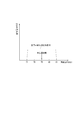
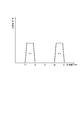
- FIG. 5 is a diagram illustrating an example of a frequency band of a transmission wave transmitted by the electronic device 1 according to one embodiment.
- the horizontal axis represents the frequency f [GHz]
- the vertical axis represents the transmission power P [W] of the transmission wave T.
- the electronic device 1 according to the embodiment described below can use a frequency band from 77 GHz to 81 GHz for transmitting the transmission wave T. That is, the electronic device 1 according to the embodiment described below can transmit the transmission wave T from the transmission antenna 40 by allocating a frequency band from 77 GHz to 81 GHz.
- the center frequency is 79 GHz.
- the electronic device 1 performs control so that the frequency of the transmission wave T does not increase when the incident angle ⁇ increases. Therefore, when the incident angle ⁇ at the time of receiving the reflected wave R does not become larger than the predetermined angle, the electronic device 1 according to the first embodiment has a relatively high frequency band that can be used for transmitting the transmission wave T. The transmission wave T is transmitted using the partial frequency. On the other hand, when the incident angle ⁇ at the time of receiving the reflected wave R becomes larger than a predetermined angle, the electronic device 1 according to the first embodiment has a relatively low frequency band that can be used for transmitting the transmission wave T. The transmission wave T is transmitted using the partial frequency.
- the frequency in the relatively high band portion may be, for example, a frequency higher than a center frequency in a frequency band that can be used for transmitting the transmission wave T.
- the frequency in the relatively low band portion may be, for example, a frequency lower than a center frequency in a frequency band that can be used for transmitting the transmission wave T.
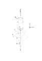
- FIG. 6 is a diagram illustrating an example in which the sensor according to the first embodiment is arranged on a moving body.
- the electronic device 1 includes a plurality of sensors 5, as illustrated in FIG. 6, the sensors 5 may be installed at a plurality of locations on the moving body 100.
- a sensor 5a is arranged at a front left portion of the moving body 100
- a sensor 5b is arranged at a right front portion of the moving body 100
- a sensor 5c is arranged at a right rear portion of the moving body 100.
- a sensor 5d is disposed at a left rear portion of the moving body 100.
- the sensor 5c can detect an object in the detection range S1 or the detection range S2.
- the detection range S1 or the detection range S2 is schematically illustrated.
- the electronic device 1 may cause the transmission wave T transmitted by the transmission antenna 40 to be included in the detection range S1.
- the electronic device 1 may include the incident angle at which the receiving antenna 50 receives the reflected wave R in the detection range S1.
- the electronic device 1 may cause the transmission wave T transmitted by the transmission antenna 40 to be included in the detection range S2.
- the electronic device 1 may include the incident angle when the receiving antenna 50 receives the reflected wave R in the detection range S2.
- the transmission wave T may be transmitted from each of the sensor 5a, the sensor 5b, and / or the sensor 5c, but is omitted for the sake of simplicity.
- only one sensor 5c will be described.
- sensors such as the sensor 5a, the sensor 5b, the sensor 5c, and the sensor 5d are not distinguished, they are simply referred to as “sensor 5”.
- the electronic device 1 can individually control the plurality of sensors 5.
- the electronic device 1 may control on / off of the plurality of sensors 5 independently of each other.
- the electronic device 1 may independently control at least one of the beam width of the transmission wave transmitted from the plurality of sensors 5 and the reach of the transmission wave.
- the electronic device 1 may independently control the operation modes (for example, the normal mode / BF mode) of the plurality of sensors 5.
- the electronic device 1 may independently control the beam forming directions of the transmission waves transmitted from the plurality of sensors 5.
- the electronic device 1 controls the beam width of the transmission wave transmitted from the plurality of sensors 5 and the reach distance of the transmission wave, etc., so that the electronic device 1 can be disposed almost all around the moving body 100 shown in FIG. , The presence or absence of an object can be detected.
- a direction perpendicular to the direction in which the plurality of receiving antennas 50 are arranged in the sensor 5c is defined as a reference direction Dn.
- the reference direction Dn shown in FIG. 6 may correspond to the reference direction (Y-axis direction shown in FIG. 3) shown in FIG.
- the electronic device 1 uses the frequency at which the transmission wave T is transmitted when the incident angle ⁇ 1 when the reception antenna 50 receives the reflected wave R becomes relatively large as in the detection range S1, for example. Select from the relatively low band portion in the possible frequency band.
- the case where the incident angle ⁇ 1 is relatively large may be the case where the incident angle ⁇ 1 is equal to or larger than a predetermined angle.
- the predetermined angle may be set to an angle based on a threshold that makes it difficult to distinguish between the phase advance / delay described with reference to FIGS. 3 and 4, such as 80 °, for example.
- FIG. 7 is a diagram illustrating an example of a frequency band of a transmission wave transmitted by another electronic device 1 according to the first embodiment.
- the horizontal axis represents the frequency f [GHz]
- the vertical axis represents the transmission power P [W] of the transmission wave T.
- the relatively low band portion is, for example, a center frequency of 79 GHz in a frequency band 77 GHz to 81 GHz usable for transmission of the transmission wave T, such as a band portion fr1 (77 GHz to 78 GHz) shown in FIG. It may be a lower band portion. Further, the relatively low band portion may be, for example, a band portion whose center frequency is lower than the center frequency of 79 GHz. That is, in this case, the center frequency of the band portion fr1 may be lower than the center frequency 79 GHz of the frequency band (77 GHz to 81 GHz) usable for transmission of the transmission wave T.
- the electronic device 1 sets the frequency at which the transmission wave T is transmitted when the angle of incidence ⁇ 2 when the receiving antenna 50 receives the reflected wave R becomes relatively small as in the detection range S2.
- the case where the incident angle ⁇ 2 is relatively small may be the case where the incident angle ⁇ 2 is smaller than a predetermined angle.
- the predetermined angle is set to an angle based on a threshold that makes it difficult to distinguish between the phase advance / delay described with reference to FIGS. May do it.
- the electronic device 1 transmits the transmission wave T using the frequency of the relatively high band portion fr2 in the frequency band 77 GHz to 81 GHz usable for transmission of the transmission wave T, as shown in FIG. 7, for example. May do it.
- the relatively high band portion is, for example, a center frequency of 79 GHz in a frequency band 77 GHz to 81 GHz usable for transmission of the transmission wave T, such as a band portion fr2 (from 80 GHz to 81 GHz) shown in FIG. It may be a higher band portion.
- the relatively high band portion may be, for example, a band portion whose center frequency is higher than the center frequency of 79 GHz. That is, in this case, the center frequency of the band portion fr2 may be higher than the center frequency 79 GHz of the frequency band (77 GHz to 81 GHz) usable for transmission of the transmission wave T.
- the relatively high band portion may be a band portion having a higher frequency than the band portion fr1.
- the frequency may not overlap the band portion fr1 as in the band portion fr2 shown in FIG.
- the relatively high band portion may be, for example, a band portion whose center frequency is higher than the center frequency of the band portion fr1. That is, in this case, the center frequency of the band portion fr2 may be higher than the center frequency of the band portion fr1. In this case, the band portion fr2 and the band portion fr1 may partially overlap.
- the electronic device 1 according to the first embodiment performs control so that the frequency of the transmission wave T does not increase when the incident angle ⁇ is equal to or larger than a predetermined angle. According to the electronic device 1 according to the first embodiment, it is avoided that the frequency of the transmission wave T increases in a situation where the incident angle ⁇ increases. For this reason, according to the electronic device 1 according to the first embodiment, the inconvenience that the phase lead / lag cannot be distinguished can be avoided, and the object detection accuracy can be improved.
- the direction of the axis of symmetry of the detection range S2 is the same as the reference direction Dn.
- the direction of the symmetry axis of the detection range S2 may be different from the reference direction Dn.
- the direction of the detection range S2 may be any direction as long as the magnitude of the incident angle ⁇ when the receiving antenna 50 receives the reflected wave R does not exceed a predetermined angle.
- the direction of the axis of symmetry of the detection range S1 may be different from the reference direction Dn.
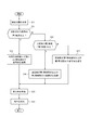
- FIG. 8 is a flowchart illustrating the operation of the electronic device 1 according to the first embodiment.
- the operation illustrated in FIG. 8 may be started, for example, when the electronic device 1 starts detecting an object 200 or the like existing around the moving object 100 or the like. That is, the operation illustrated in FIG. 8 may be started when an object is detected using the sensor 5 of the electronic device 1.
- the detection range determination unit 14 of the control unit 10 determines a range in which an object is detected based on the transmission wave T and the reflected wave R (Step S11). In step S11, the detection range determination unit 14 may determine whether the detection range of the sensor 5c illustrated in FIG. 6 is the detection range S1 or the detection range S2, for example.
- the detection range determination unit 14 may determine, for example, a range defined by default as a detection range. In step S11, the detection range determination unit 14 may determine the detection range based on, for example, the position of the object detected by the transmission wave T of the previous frame. In this case, the detection range determination unit 14 may determine the detection range based on the detection result of the object by at least one of the distance estimation unit 62, the angle estimation unit 64, and the relative speed estimation unit 66.
- step S12 the control unit 10 determines whether the incident angle ⁇ of the reflected wave R is equal to or greater than a predetermined angle (step S12).
- the predetermined angle is appropriately set to an angle based on a threshold value, such as 80 degrees, as described above, which makes it difficult to distinguish between leading and lagging the phase described in FIGS. May do it. That is, in step S12, if the incident angle ⁇ of the reflected wave R becomes equal to or larger than a predetermined angle, an angle may be set such that it is difficult to distinguish between the phase advance / delay described with reference to FIGS.
- the frequency selection unit 16 selects a frequency of the first band lower than the predetermined frequency in the predetermined frequency band (step S12).
- the predetermined frequency band may be a frequency band (for example, from 77 GHz to 81 GHz) usable for detection, as described above.
- the first band lower than the predetermined frequency may be, for example, the band fr1 shown in FIG.
- the predetermined frequency may be, for example, the center frequency (79 GHz) shown in FIG.
- the control unit 10 transmits the transmission wave T from the transmission antenna 40 using the selected frequency.
- the frequency selecting unit 16 selects a frequency of the second band portion higher than the predetermined frequency in the predetermined frequency band.
- the predetermined frequency band may be a frequency band (for example, from 77 GHz to 81 GHz) usable for detection, as described above.
- the second band portion higher than the predetermined frequency may be, for example, the band portion fr2 shown in FIG.
- the predetermined frequency may be, for example, the center frequency (79 GHz) shown in FIG.
- the control unit 10 transmits the transmission wave T from the transmission antenna 40 using the selected frequency.
- the electronic device 1 receives the reflected waves R from the plurality of receiving antennas 50 (Step S15).
- the electronic device 1 detects an object existing around the electronic device 1 (or the moving body 100) such as the object 200 (step S16).
- the control unit 10 may detect the presence of the object based on the estimation result of at least one of the distance estimation unit 62, the angle estimation unit 64, and the relative speed estimation unit 66.
- step S16 The detection of the object in step S16 can be performed based on various algorithms and the like using a known millimeter-wave radar technique, and thus a more detailed description is omitted.
- the control unit 10 may start the process of step S11 again.
- the control unit 10 detects an object that reflects the transmission wave T based on the transmission signal transmitted as the transmission wave T and the reception signal received as the reflected wave R. In addition, the control unit 10 determines a band portion for transmitting the transmission wave T in a predetermined frequency band (for example, a frequency band that can be used for detection) according to the incident angle ⁇ when the receiving antenna 50 receives the reflected wave R. decide.
- the incident angle ⁇ may be an angle formed by a straight line corresponding to the direction in which the reflected wave R enters the receiving antenna 50 and a perpendicular to the direction in which the plurality of receiving antennas 50 are arranged.
- the control unit 10 when the incident angle ⁇ is equal to or larger than a predetermined angle, the control unit 10 controls the frequency of a band portion for transmitting the transmission wave T to be equal to or lower than a predetermined frequency in a predetermined frequency band. You may. In the first embodiment, when the incident angle ⁇ is equal to or larger than the predetermined first angle, the control unit 10 controls the frequency of the band transmitting the transmission wave T to be lower than the center frequency of the predetermined frequency band. It may be.
- the control unit 10 when the incident angle ⁇ is equal to or larger than the first angle, controls the center frequency of the band transmitting the transmission wave T to be lower than the center frequency of the predetermined frequency band. You may. Further, in the first embodiment, when the incident angle ⁇ is smaller than the first angle, the control unit 10 sets the center frequency of the band transmitting the transmission wave T to be equal to or higher than the center frequency of the predetermined frequency band. You may.
- the frequency of the transmission wave T is controlled to be low when the incident angle ⁇ is large. For this reason, according to the electronic device 1 according to the first embodiment, the inconvenience that the phase lead / lag cannot be distinguished is avoided, and the object reflecting the transmission wave T is detected with high accuracy.
- the band portion for transmitting the transmission wave T in the usable frequency band is divided into two according to the incident angle ⁇ when the receiving antenna 50 receives the reflected wave R (FIG. 6). And FIG. 7).
- the electronic device 1 operates in a usable frequency band in accordance with the incident angle ⁇ when the receiving antenna 50 receives the reflected wave R.
- the band portion for transmitting the transmission wave T is divided into three.
- description that is the same as or similar to the first embodiment will be appropriately simplified or omitted.
- FIG. 9 is a diagram illustrating an example in which the sensor according to the second embodiment is arranged on a moving body. In FIG. 9, only one sensor 5e is described, and other sensors 5 are omitted for simplification of description.
- a sensor 5e is disposed at the rear center of the moving body 100. Further, as shown in FIG. 9, the sensor 5e can detect an object in the detection range S1, the detection range S2, or the detection range S3. In FIG. 9, the detection range S1, the detection range S2, and the detection range S3 are schematically illustrated.
- the electronic device 1 determines that the transmission wave T transmitted by the transmission antenna 40 is the detection range S1, the detection range S2, or the detection range, respectively. It may be included in S3.
- the electronic device 1 determines that the incident angle when the receiving antenna 50 receives the reflected wave R is the detection range S1, It may be included in the detection range S2 or the detection range S3.
- a direction perpendicular to the direction in which the plurality of receiving antennas 50 are arranged in the sensor 5e is defined as a reference direction Dn.
- the reference direction Dn shown in FIG. 9 may correspond to the reference direction (Y-axis direction shown in FIG. 3) shown in FIG.
- the electronic device 1 uses the frequency at which the transmission wave T is transmitted when the incident angle ⁇ 1 when the receiving antenna 50 receives the reflected wave R becomes relatively large, for example, in the detection range S1. Select from the relatively low band portion in the possible frequency band.
- the case where the incident angle ⁇ 1 is relatively large may be the case where the incident angle ⁇ 1 is equal to or larger than the first angle.
- the first angle may be appropriately set to an angle based on a threshold that makes it difficult to distinguish between leading and lagging of the phase described in FIGS.
- the electronic device 1 may transmit the transmission wave T using a frequency of a relatively low band portion fr1 in a frequency band that can be used for transmitting the transmission wave T, for example, as illustrated in FIG.
- FIG. 10 is a diagram illustrating an example of a frequency band of a transmission wave transmitted by another electronic device 1 according to the second embodiment.
- the relatively low band portion fr1 may be the same as in the above-described first embodiment.
- the incident angle ⁇ 2 when the receiving antenna 50 receives the reflected wave R as in the detection range S2 is equal to or larger than a second angle smaller than the first angle.
- the electronic device 1 according to the second embodiment selects the frequency for transmitting the transmission wave T from the second band portion where the frequency is equal to or higher than the first band portion in the usable frequency band.
- the second angle may be an arbitrary angle (for example, 20 ° or the like) smaller than the above-described first angle.
- the electronic device 1 uses the frequency of the second band portion fr2 whose frequency is higher than the first band in the frequency band that can be used for transmitting the transmission wave T to transmit the transmission wave.
- T may be transmitted.
- the second band portion is, for example, around a center frequency of 79 GHz in a frequency band usable for transmission of the transmission wave T, such as a band portion fr2 (from 78.5 GHz to 79.5 GHz) shown in FIG. Band portion.
- the second band portion fr2 may be, for example, a band portion having a higher center frequency than the center frequency of the first band portion. That is, in this case, the center frequency of the band portion fr2 may be higher than the center frequency 77.5 GHz of the first band portion.
- the electronic device 1 selects the frequency for transmitting the transmission wave T from the third band portion where the frequency is equal to or higher than the second band portion in the usable frequency band.
- the electronic device 1 uses the frequency of the third band portion fr3 whose frequency is higher than the second band in the frequency band that can be used for transmitting the transmission wave T to transmit the transmission wave.
- T may be transmitted.
- the third band portion is, for example, a band portion around a maximum frequency 81 GHz in a frequency band usable for transmission of the transmission wave T, such as a band portion fr3 (from 80 GHz to 81 GHz) shown in FIG. Good.
- the third band portion fr3 may be, for example, a band portion having a higher center frequency than the center frequency of the first band portion.
- the third band portion fr3 may be, for example, a band portion having a higher center frequency than the center frequency of the second band portion. That is, in these cases, the center frequency of the band portion fr3 may be higher than the center frequency of the first band portion and / or the center frequency of the second band portion.
- the first band portion fr1, the second band portion fr2, and the third band portion fr3 may be band portions having no overlap. Further, the first band portion fr1, the second band portion fr2, and the third band portion fr3 may each be a band portion having at least partial overlap.
- the electronic device 1 according to the second embodiment controls the frequency of the transmission wave T not to increase when the incident angle ⁇ is equal to or greater than the first angle. According to the electronic device 1 according to the second embodiment, it is avoided that the frequency of the transmission wave T increases in a situation where the incident angle ⁇ increases. For this reason, even with the electronic device 1 according to the second embodiment, the inconvenience that the lead / lag of the phase cannot be distinguished can be avoided, and the detection accuracy of the object can be improved.
- FIG. 11 is a flowchart illustrating the operation of the electronic device 1 according to the second embodiment.
- points different from the operations illustrated in FIG. 8 will be mainly described, and descriptions that are the same as or similar to the operations illustrated in FIG. 8 will be appropriately simplified or omitted.
- the control unit 10 determines whether or not the incident angle ⁇ of the reflected wave R is equal to or greater than the first angle (step S21).
- the first angle may be the same as the predetermined angle in step S12 shown in FIG. 8, or may be different.
- the first angle may be appropriately set to an angle based on a threshold such as 80 °, for example, which makes it difficult to distinguish between leading and lagging of the phase described in FIGS. 3 and 4.
- step S21 If it is determined in step S21 that the incident angle ⁇ of the reflected wave R is equal to or larger than the predetermined angle, the same operation as in step S13 and subsequent steps shown in FIG. 8 may be performed.
- the frequency selection unit 16 may select a frequency (from 77 GHz to 78 GHz) in the band portion fr1 shown in FIG. 10, for example.
- step S21 when it is determined in step S21 that the incident angle ⁇ of the reflected wave R is smaller than the predetermined angle, the control unit 10 determines whether the incident angle ⁇ of the reflected wave R is equal to or greater than the second angle (step S21).
- the second angle may be an angle smaller than the above-described first angle, such as 20 °, for example.
- step S22 If it is determined in step S22 that the incident angle ⁇ of the reflected wave R is equal to or larger than the second angle, the same operation as in step S14 and subsequent steps shown in FIG. 8 may be performed.
- the frequency selection unit 16 may select, for example, a frequency (from 78.5 GHz to 79.5 GHz) in the band portion fr2 shown in FIG.
- the frequency selecting unit 16 determines that the transmission wave T has a frequency in the third band portion where the frequency is equal to or more than the second band portion. Transmit (step S23).
- the frequency selection unit 16 may select, for example, a frequency (from 80 GHz to 81 GHz) in the band portion fr3 illustrated in FIG.
- step S23 the same operation as that after step S15 shown in FIG. 8 may be performed. Further, after step S16 shown in FIG. 11, the control unit 10 may start the process of step S11 again.
- the control unit 10 sets the center frequency of the band transmitting the transmission wave T to the predetermined frequency, for example.
- the frequency may be higher than a predetermined frequency higher than the center frequency of the band.
- the frequency of the transmission wave T is controlled to be low when the incident angle ⁇ is large. For this reason, according to the electronic device 1 according to the second embodiment, the inconvenience that the lead / lag of the phase cannot be distinguished is avoided, and the object reflecting the transmission wave T is detected with high accuracy. Further, according to the electronic device 1 according to the second embodiment, as shown in FIG. 9, the detection range can be adaptively changed according to the detection use of the sensor 5 and / or the detection target.
- the electronic device 1 according to the third embodiment variably controls the predetermined angle to be compared with the incident angle ⁇ of the reflected wave R in the electronic device 1 according to the first embodiment described above.
- the predetermined angle to be compared with the incident angle ⁇ of the reflected wave R is appropriately set.
- the predetermined angle to be compared with the incident angle ⁇ of the reflected wave R is set based on the detection result of the object.
- FIG. 12 is a diagram illustrating an example in which the sensor according to the third embodiment is arranged on a moving object. In FIG. 12, as in FIG. 6, only one sensor 5c will be described.
- the sensor 5c can detect the object in the detection range S2.
- the incident angle ⁇ when the receiving antenna 50 of the sensor 5c receives the reflected wave R becomes relatively small (not a large angle). Therefore, when an object is detected in the detection range S2, a situation in which it is difficult to distinguish between the phase advance / delay described in FIGS. 3 and 4 does not occur.
- the sensor 5c can detect an object in the detection range S1. Then, the incident angle ⁇ when the receiving antenna 50 of the sensor 5c receives the reflected wave R becomes relatively large. Then, a situation may occur in which it is not possible to distinguish between the lead / lag of the phase as described above.
- the transmission wave T May be set to be lower than or equal to a predetermined frequency.
- the frequency at which the transmission wave T is transmitted is the frequency in the band portion fr1 shown in FIG.
- the frequency at which the transmission wave T is transmitted is the frequency in the band portion fr2 shown in FIG. That situation can occur.
- the third embodiment when detecting the object 200 ′ shown in FIG.
- FIG. 13 is a flowchart illustrating the operation of the electronic device 1 according to the third embodiment.
- the operation of the electronic device 1 according to the third embodiment shown in FIG. 13 is different from the operation shown in FIG. 8 in that step S12 is changed. Therefore, hereinafter, the points different from the operation illustrated in FIG. 8 will be mainly described, and description that is the same as or similar to the operation illustrated in FIG. 8 will be appropriately simplified or omitted.
- step S31 the control unit 10 determines whether or not the position of the already detected object is equal to or larger than a predetermined angle (step S31).
- step S31 immediately after the operation shown in FIG. 13 is started, it is assumed that no object has been detected yet. In such a case, the process proceeds to step S14, and the frequency selecting unit 16 may transmit the transmission wave T at a relatively high frequency such as the frequency in the band portion fr2 shown in FIG.
- step S14 the same operation as that after step S15 shown in FIG. 8 may be performed.
- step S16 shown in FIG. 13 the control unit 10 may start the process of step S11 again.
- step S31 the control unit 10 determines whether or not the position of the object detected in step S16 is equal to or larger than a predetermined angle.
- the predetermined angle is an angle based on a threshold value such as 80 °, for example, which is indistinguishable between phase advance / delay described with reference to FIGS. May be appropriately set.
- step S31 it may be determined whether an angle from the sensor 5c toward the object 200 is equal to or larger than a predetermined angle with reference to the reference direction Dn shown in FIG.
- step S31 If it is determined in step S31 that the position of the object is equal to or larger than the predetermined angle, the same operation as in step S13 and subsequent steps shown in FIG. 8 may be performed.
- the frequency selecting unit 16 may select, for example, a frequency (from 77 GHz to 78 GHz) in the band portion fr1 shown in FIG.
- the frequency selection unit 16 may select, for example, a frequency (from 80 GHz to 81 GHz) in the band portion fr2 illustrated in FIG.
- the electronic device 1 repeats the operation illustrated in FIG. 13, so that, for example, even if the object 200 is moving, the frequency band transmitting the transmission wave T is changed according to the movement of the object 200. Can be changed dynamically.
- control unit 10 may determine a band portion for transmitting the transmission wave T in a predetermined frequency band based on the detected position of the object. Further, in the third embodiment, the control unit 10 may dynamically change the band portion for transmitting the transmission wave T in a predetermined frequency band according to the position of the detected object.
- the electronic device 1 according to the third embodiment also controls the frequency of the transmission wave T to be lower as the angle of the position of the object increases, that is, in a situation where the incident angle ⁇ increases. For this reason, according to the electronic device 1 of the third embodiment, the inconvenience that the lead / lag of the phase cannot be distinguished is avoided, and the object that reflects the transmission wave T is detected with high accuracy. Further, according to the electronic device 1 according to the third embodiment, as shown in FIG. 12, the band of the frequency at which the transmission wave T is transmitted moves according to the position of the moving object 200 (the object 200 ′). Can be changed.
- each functional unit, each means, each step, and the like are added to another embodiment so as not to be logically inconsistent, or each functional unit, each means, each step, and the like in another embodiment are used. It is possible to replace Further, in each embodiment, a plurality of functional units, each means, each step, and the like can be combined into one or divided. Further, each embodiment of the present disclosure described above is not limited to being faithfully implemented in each of the embodiments described above, and may be implemented by appropriately combining the features or omitting some of them. You can also.
- the electronic device 1 makes the band partial frequency for transmitting the transmission wave T a relatively low frequency, for example, the frequency in the band fr1 shown in FIG. You may do so.
- the frequency to be used is f [GHz].
- the phase difference caused by the path difference D needs to be half or less (180 ° or less) of ⁇ ′.
- the embodiments described above are not limited only to the implementation as the electronic device 1.
- the above-described embodiment may be implemented as a control method for a device such as the electronic device 1.
- the above-described embodiment may be implemented as a control program for a device such as the electronic device 1.
- the number of the transmitting antennas 40 and the number of the receiving antennas 50 are both two. However, in one embodiment, the number of the transmitting antennas 40 and the number of the receiving antennas 50 may be arbitrary. When three or more transmitting antennas 40 and receiving antennas 50 are used, one of the plurality of transmitting antennas 40 and the plurality of receiving antennas 50 may be used as a reference antenna. In this case, the phase of the transmission wave transmitted by the transmission antenna 40 is controlled in accordance with the path difference D in a predetermined direction between the transmission wave transmitted by the reference antenna and the transmission wave transmitted by the other transmission antenna 40. Beam forming may be performed.
- the electronic device 1 may include, for example, only the control unit 10.
- the electronic device 1 according to one embodiment includes at least the signal generation unit 22, the frequency synthesizer 24, the transmission control unit 30, the power amplifier 36, and the transmission antenna 40 as shown in FIG. Any of these may be included as appropriate.
- the electronic device 1 according to one embodiment may include the reception antenna 50, the LNA 52, the mixer 54, the IF unit 56, the AD conversion unit, instead of or in addition to the above-described function unit. 58, at least one of the distance estimating unit 62, the angle estimating unit 64, and the relative speed estimating unit 66 may be appropriately included.
- the electronic device 1 according to the embodiment can have various configurations. Further, when the electronic device 1 according to an embodiment is mounted on the moving body 100, for example, at least one of the above-described functional units may be installed at an appropriate place such as inside the moving body 100. On the other hand, in one embodiment, for example, at least one of the transmitting antenna 40 and the receiving antenna 50 may be installed outside the moving body 100.
Abstract
Description
送信波を送信する複数の送信アンテナと、
前記送信波が反射された反射波を受信する複数の受信アンテナと、
前記送信波として送信される送信信号及び前記反射波として受信される受信信号に基づいて、前記送信波を反射する物体を検出する制御部と、を備える。
前記制御部は、前記受信アンテナが前記反射波を受信する際の入射角に応じて、前記送信波を所定の周波数帯域において送信する帯域部分を決定する。
(1)複数の送信アンテナから送信波を送信するステップ
(2)前記送信波が反射された反射波を複数の受信アンテナから受信するステップ
(3)前記送信波として送信される送信信号及び前記反射波として受信される受信信号に基づいて、前記送信波を反射する物体を検出するステップ
(4)前記受信アンテナが前記反射波を受信する際の入射角に応じて、前記送信波を所定の周波数帯域において送信する帯域部分を決定するステップ
上述のように、一実施形態に係る電子機器1は、入射角θが大きくなる状況において、送信波Tの周波数が高くならないように制御する。そこで、第1実施形態に係る電子機器1は、反射波Rを受信する際の入射角θが所定の角度以上に大きくならない場合、送信波Tの送信に使用可能な周波数帯域において比較的高い帯域部分の周波数を使用して送信波Tを送信する。一方、第1実施形態に係る電子機器1は、反射波Rを受信する際の入射角θが所定の角度以上に大きくなる場合、送信波Tの送信に使用可能な周波数帯域において比較的低い帯域部分の周波数を使用して送信波Tを送信する。ここで、比較的高い帯域部分の周波数とは、例えば送信波Tの送信に使用可能な周波数帯域における中心周波数よりも高い周波数としてよい。また、比較的低い帯域部分の周波数とは、例えば送信波Tの送信に使用可能な周波数帯域における中心周波数よりも低い周波数としてよい。以下、第1実施形態に係る電子機器1の動作について、さらに説明する。
次に、第2実施形態に係る電子機器1について説明する。
次に、第3実施形態に係る電子機器1について説明する。
5 センサ
10 制御部
12 記憶部
14 検出範囲決定部
16 周波数選定部
22 信号生成部
24 周波数シンセサイザ
30 送信制御部
32 位相制御部
34 パワー制御部
36 パワーアンプ
40 送信アンテナ
50 受信アンテナ
52 LNA
54 ミキサ
56 IF部
58 AD変換部
62 距離推定部
64 角度推定部
66 相対速度推定部
100 移動体
200 物体
Claims (11)
- 送信波を送信する複数の送信アンテナと、
前記送信波が反射された反射波を受信する複数の受信アンテナと、
前記送信波として送信される送信信号及び前記反射波として受信される受信信号に基づいて、前記送信波を反射する物体を検出する制御部と、
を備える電子機器であって、
前記制御部は、前記受信アンテナが前記反射波を受信する際の入射角に応じて、前記送信波を所定の周波数帯域において送信する帯域部分を決定する、電子機器。 - 前記入射角は、前記反射波が前記受信アンテナに入射する方向に対応する直線が、前記複数の受信アンテナが配置される方向の垂線となす角である、請求項1に記載の電子機器。
- 前記制御部は、前記入射角が所定の角度以上になる場合、前記帯域部分の周波数が前記所定の周波数帯域において所定の周波数以下になるようにする、請求項1又は2に記載の電子機器。
- 前記制御部は、前記入射角が第1角度以上になる場合、前記帯域部分の周波数が、前記所定の周波数帯域の中心周波数より低くなるようにする、請求項1から3のいずれかに記載の電子機器。
- 前記制御部は、前記入射角が前記第1角度以上になる場合、前記帯域部分の中心周波数が、前記所定の周波数帯域の中心周波数より低くなるようにする、請求項4に記載の電子機器。
- 前記制御部は、前記入射角が前記第1角度より小さくなる場合、前記帯域部分の中心周波数が、前記所定の周波数帯域の中心周波数以上になるようにする、請求項5に記載の電子機器。
- 前記制御部は、前記入射角が前記第1角度より小さい第2角度よりも小さくなる場合、前記帯域部分の中心周波数が、前記所定の周波数帯域の中心周波数より高い所定の周波数以上になるようにする、請求項6に記載の電子機器。
- 前記制御部は、前記物体の位置に基づいて、前記送信波を所定の周波数帯域において送信する帯域部分を決定する、請求項1に記載の電子機器。
- 前記制御部は、前記物体の位置に応じて、前記送信波を所定の周波数帯域において送信する帯域部分を動的に可変にする、請求項8に記載の電子機器。
- 複数の送信アンテナから送信波を送信するステップと、
前記送信波が反射された反射波を複数の受信アンテナから受信するステップと、
前記送信波として送信される送信信号及び前記反射波として受信される受信信号に基づいて、前記送信波を反射する物体を検出するステップと、
前記受信アンテナが前記反射波を受信する際の入射角に応じて、前記送信波を所定の周波数帯域において送信する帯域部分を決定するステップと、
を含む、電子機器の制御方法。 - コンピュータに、
複数の送信アンテナから送信波を送信するステップと、
前記送信波が反射された反射波を複数の受信アンテナから受信するステップと、
前記送信波として送信される送信信号及び前記反射波として受信される受信信号に基づいて、前記送信波を反射する物体を検出するステップと、
前記受信アンテナが前記反射波を受信する際の入射角に応じて、前記送信波を所定の周波数帯域において送信する帯域部分を決定するステップと、
を実行させる、電子機器の制御プログラム。
Priority Applications (4)
| Application Number | Priority Date | Filing Date | Title |
|---|---|---|---|
| US17/282,338 US20210349181A1 (en) | 2018-10-05 | 2019-09-26 | Electronic device, control method of electronic device, and control program of electronic device |
| JP2020500221A JPWO2020071243A1 (ja) | 2018-10-05 | 2019-09-26 | 電子機器、電子機器の制御方法、及び電子機器の制御プログラム |
| EP19869462.2A EP3862783A4 (en) | 2018-10-05 | 2019-09-26 | Electronic device, electronic device control method, and electronic device control program |
| CN201980065017.6A CN112789517A (zh) | 2018-10-05 | 2019-09-26 | 电子设备、电子设备的控制方法以及电子设备的控制程序 |
Applications Claiming Priority (2)
| Application Number | Priority Date | Filing Date | Title |
|---|---|---|---|
| JP2018190428 | 2018-10-05 | ||
| JP2018-190428 | 2018-10-05 |
Publications (1)
| Publication Number | Publication Date |
|---|---|
| WO2020071243A1 true WO2020071243A1 (ja) | 2020-04-09 |
Family
ID=70054989
Family Applications (1)
| Application Number | Title | Priority Date | Filing Date |
|---|---|---|---|
| PCT/JP2019/037919 WO2020071243A1 (ja) | 2018-10-05 | 2019-09-26 | 電子機器、電子機器の制御方法、及び電子機器の制御プログラム |
Country Status (5)
| Country | Link |
|---|---|
| US (1) | US20210349181A1 (ja) |
| EP (1) | EP3862783A4 (ja) |
| JP (2) | JPWO2020071243A1 (ja) |
| CN (1) | CN112789517A (ja) |
| WO (1) | WO2020071243A1 (ja) |
Citations (5)
| Publication number | Priority date | Publication date | Assignee | Title |
|---|---|---|---|---|
| JPS63501443A (ja) * | 1985-06-13 | 1988-06-02 | プレツシ− オ−バ−シ−ズ リミテツド | レーダシステムにおけるまたは関する改良 |
| JP2001211022A (ja) * | 2000-01-25 | 2001-08-03 | Nippon Telegr & Teleph Corp <Ntt> | アレイアンテナおよびその周波数走査方法 |
| JP2007017294A (ja) * | 2005-07-07 | 2007-01-25 | Nissan Motor Co Ltd | レーダ装置およびその指向性制御方法 |
| JP2015155883A (ja) | 2014-01-15 | 2015-08-27 | パナソニック株式会社 | レーダ装置 |
| US20180128911A1 (en) * | 2016-11-07 | 2018-05-10 | Mando Corporation | Object-sensing system for vehicle and object-sensing method for vehicle |
Family Cites Families (20)
| Publication number | Priority date | Publication date | Assignee | Title |
|---|---|---|---|---|
| JPS5984175A (ja) * | 1982-11-05 | 1984-05-15 | Toshiba Corp | 超音波測定装置 |
| JPS59193380A (ja) * | 1983-04-18 | 1984-11-01 | Yokogawa Medical Syst Ltd | 方位角適応型フエ−ズド・アレイ・ソ−ナ− |
| JP2545958B2 (ja) * | 1988-12-16 | 1996-10-23 | 三菱電機株式会社 | ディジタルビームフォーミングレーダ |
| JP3242864B2 (ja) * | 1997-06-12 | 2001-12-25 | アロカ株式会社 | 超音波診断装置および超音波診断用の超音波送受信方法 |
| JP2000258524A (ja) * | 1999-03-08 | 2000-09-22 | Toyota Motor Corp | レーダ装置 |
| US6606077B2 (en) * | 1999-11-18 | 2003-08-12 | Automotive Systems Laboratory, Inc. | Multi-beam antenna |
| JP4156307B2 (ja) * | 2002-09-09 | 2008-09-24 | 株式会社デンソー | レーダ装置、プログラム |
| WO2004070873A1 (en) * | 2003-02-03 | 2004-08-19 | Telefonaktiebolaget Lm Ericsson (Publ) | A method for controlling a radar antenna |
| JP4614646B2 (ja) * | 2003-10-17 | 2011-01-19 | トヨタ自動車株式会社 | 車輌の障害物検出レーダー装置 |
| US7667637B2 (en) * | 2004-04-05 | 2010-02-23 | Weibel Scientific A/S | System and method for radar detection of an object |
| JP4302750B2 (ja) * | 2007-03-29 | 2009-07-29 | 古河電気工業株式会社 | 複合モードレーダ装置 |
| DE102008054624A1 (de) * | 2008-12-15 | 2010-06-17 | Robert Bosch Gmbh | FMCW-Radarsensor für Kraftfahrzeuge |
| JP5473386B2 (ja) * | 2009-04-22 | 2014-04-16 | 三菱電機株式会社 | レーダ装置 |
| JP5600464B2 (ja) * | 2010-04-02 | 2014-10-01 | 日本電産エレシス株式会社 | レーダ装置及びコンピュータプログラム |
| US8405541B2 (en) * | 2010-09-01 | 2013-03-26 | Toyota Motor Engineering & Manufacturing North America, Inc. | Multi-range radar system |
| JP2012108075A (ja) * | 2010-11-19 | 2012-06-07 | Furuno Electric Co Ltd | レーダ装置及び物標検出方法 |
| DE102013205892A1 (de) * | 2013-04-03 | 2014-10-09 | Robert Bosch Gmbh | Radarvorrichtung und Verfahren zum Betrieb einer Radarvorrichtung |
| KR101485077B1 (ko) * | 2014-05-09 | 2015-01-21 | 엘아이지넥스원 주식회사 | 은신 객체 탐지 방법 |
| US20160274758A1 (en) * | 2015-03-20 | 2016-09-22 | Thalmic Labs Inc. | Systems, devices, and methods for mitigating false positives in human-electronics interfaces |
| JP5997803B2 (ja) * | 2015-05-22 | 2016-09-28 | 株式会社日立製作所 | 無線送信機、無線受信機、無線通信システム、昇降機制御システムおよび変電設備制御システム |
-
2019
- 2019-09-26 EP EP19869462.2A patent/EP3862783A4/en active Pending
- 2019-09-26 CN CN201980065017.6A patent/CN112789517A/zh active Pending
- 2019-09-26 US US17/282,338 patent/US20210349181A1/en active Pending
- 2019-09-26 JP JP2020500221A patent/JPWO2020071243A1/ja active Pending
- 2019-09-26 WO PCT/JP2019/037919 patent/WO2020071243A1/ja active Application Filing
-
2021
- 2021-07-16 JP JP2021118278A patent/JP2021165758A/ja active Pending
Patent Citations (5)
| Publication number | Priority date | Publication date | Assignee | Title |
|---|---|---|---|---|
| JPS63501443A (ja) * | 1985-06-13 | 1988-06-02 | プレツシ− オ−バ−シ−ズ リミテツド | レーダシステムにおけるまたは関する改良 |
| JP2001211022A (ja) * | 2000-01-25 | 2001-08-03 | Nippon Telegr & Teleph Corp <Ntt> | アレイアンテナおよびその周波数走査方法 |
| JP2007017294A (ja) * | 2005-07-07 | 2007-01-25 | Nissan Motor Co Ltd | レーダ装置およびその指向性制御方法 |
| JP2015155883A (ja) | 2014-01-15 | 2015-08-27 | パナソニック株式会社 | レーダ装置 |
| US20180128911A1 (en) * | 2016-11-07 | 2018-05-10 | Mando Corporation | Object-sensing system for vehicle and object-sensing method for vehicle |
Also Published As
| Publication number | Publication date |
|---|---|
| US20210349181A1 (en) | 2021-11-11 |
| EP3862783A4 (en) | 2022-06-29 |
| JP2021165758A (ja) | 2021-10-14 |
| CN112789517A (zh) | 2021-05-11 |
| JPWO2020071243A1 (ja) | 2021-02-15 |
| EP3862783A1 (en) | 2021-08-11 |
Similar Documents
| Publication | Publication Date | Title |
|---|---|---|
| US20210341598A1 (en) | Electronic device, control method of electronic device, and control program of electronic device | |
| JP6746017B2 (ja) | 電子機器、電子機器の制御方法、及び電子機器の制御プログラム | |
| JP7174668B2 (ja) | 電子機器、電子機器の制御方法、及び電子機器の制御プログラム | |
| US20220146625A1 (en) | Electronic device, and method and program for controlling the same | |
| JP7161076B2 (ja) | 電子機器、電子機器の制御方法、及びプログラム | |
| WO2020071243A1 (ja) | 電子機器、電子機器の制御方法、及び電子機器の制御プログラム | |
| WO2020066497A1 (ja) | 電子機器、電子機器の制御方法、及び電子機器の制御プログラム | |
| WO2020017290A1 (ja) | 電子機器、電子機器の制御方法、及び電子機器の制御プログラム | |
| WO2020059481A1 (ja) | 電子機器、電子機器の制御方法、及び電子機器の制御プログラム | |
| WO2020071242A1 (ja) | 電子機器、電子機器の制御方法、及び電子機器の制御プログラム | |
| JP7307244B2 (ja) | 電子機器、電子機器の制御方法、及びプログラム | |
| WO2020044959A1 (ja) | 電子機器、電子機器の制御方法、及び電子機器の制御プログラム | |
| WO2023002870A1 (ja) | 電子機器、電子機器の制御方法、及びプログラム |
Legal Events
| Date | Code | Title | Description |
|---|---|---|---|
| ENP | Entry into the national phase |
Ref document number: 2020500221 Country of ref document: JP Kind code of ref document: A |
|
| 121 | Ep: the epo has been informed by wipo that ep was designated in this application |
Ref document number: 19869462 Country of ref document: EP Kind code of ref document: A1 |
|
| NENP | Non-entry into the national phase |
Ref country code: DE |
|
| WWE | Wipo information: entry into national phase |
Ref document number: 2019869462 Country of ref document: EP |
|
| ENP | Entry into the national phase |
Ref document number: 2019869462 Country of ref document: EP Effective date: 20210506 |