WO2020071097A1 - 冷凍サイクル装置 - Google Patents
冷凍サイクル装置Info
- Publication number
- WO2020071097A1 WO2020071097A1 PCT/JP2019/036255 JP2019036255W WO2020071097A1 WO 2020071097 A1 WO2020071097 A1 WO 2020071097A1 JP 2019036255 W JP2019036255 W JP 2019036255W WO 2020071097 A1 WO2020071097 A1 WO 2020071097A1
- Authority
- WO
- WIPO (PCT)
- Prior art keywords
- refrigerant
- unit
- cooling
- heat exchange
- pressure
- Prior art date
- Legal status (The legal status is an assumption and is not a legal conclusion. Google has not performed a legal analysis and makes no representation as to the accuracy of the status listed.)
- Ceased
Links
Images




Classifications
-
- B—PERFORMING OPERATIONS; TRANSPORTING
- B60—VEHICLES IN GENERAL
- B60H—ARRANGEMENTS OF HEATING, COOLING, VENTILATING OR OTHER AIR-TREATING DEVICES SPECIALLY ADAPTED FOR PASSENGER OR GOODS SPACES OF VEHICLES
- B60H1/00—Heating, cooling or ventilating devices
- B60H1/32—Cooling devices
-
- F—MECHANICAL ENGINEERING; LIGHTING; HEATING; WEAPONS; BLASTING
- F25—REFRIGERATION OR COOLING; COMBINED HEATING AND REFRIGERATION SYSTEMS; HEAT PUMP SYSTEMS; MANUFACTURE OR STORAGE OF ICE; LIQUEFACTION SOLIDIFICATION OF GASES
- F25B—REFRIGERATION MACHINES, PLANTS OR SYSTEMS; COMBINED HEATING AND REFRIGERATION SYSTEMS; HEAT PUMP SYSTEMS
- F25B1/00—Compression machines, plants or systems with non-reversible cycle
-
- F—MECHANICAL ENGINEERING; LIGHTING; HEATING; WEAPONS; BLASTING
- F25—REFRIGERATION OR COOLING; COMBINED HEATING AND REFRIGERATION SYSTEMS; HEAT PUMP SYSTEMS; MANUFACTURE OR STORAGE OF ICE; LIQUEFACTION SOLIDIFICATION OF GASES
- F25B—REFRIGERATION MACHINES, PLANTS OR SYSTEMS; COMBINED HEATING AND REFRIGERATION SYSTEMS; HEAT PUMP SYSTEMS
- F25B39/00—Evaporators; Condensers
- F25B39/04—Condensers
-
- F—MECHANICAL ENGINEERING; LIGHTING; HEATING; WEAPONS; BLASTING
- F25—REFRIGERATION OR COOLING; COMBINED HEATING AND REFRIGERATION SYSTEMS; HEAT PUMP SYSTEMS; MANUFACTURE OR STORAGE OF ICE; LIQUEFACTION SOLIDIFICATION OF GASES
- F25B—REFRIGERATION MACHINES, PLANTS OR SYSTEMS; COMBINED HEATING AND REFRIGERATION SYSTEMS; HEAT PUMP SYSTEMS
- F25B43/00—Arrangements for separating or purifying gases or liquids; Arrangements for vaporising the residuum of liquid refrigerant, e.g. by heat
-
- F—MECHANICAL ENGINEERING; LIGHTING; HEATING; WEAPONS; BLASTING
- F25—REFRIGERATION OR COOLING; COMBINED HEATING AND REFRIGERATION SYSTEMS; HEAT PUMP SYSTEMS; MANUFACTURE OR STORAGE OF ICE; LIQUEFACTION SOLIDIFICATION OF GASES
- F25B—REFRIGERATION MACHINES, PLANTS OR SYSTEMS; COMBINED HEATING AND REFRIGERATION SYSTEMS; HEAT PUMP SYSTEMS
- F25B6/00—Compression machines, plants or systems, with several condenser circuits
- F25B6/04—Compression machines, plants or systems, with several condenser circuits arranged in series
Definitions
- the present disclosure relates to a refrigeration cycle device including a liquid storage unit.
- Patent Document 1 discloses a refrigeration cycle apparatus including an accumulator as a liquid storage unit.
- the accumulator is a low-pressure storage unit that separates gas-liquid refrigerant flowing out of the evaporator and stores the separated low-pressure liquid-phase refrigerant.
- the cooling capacity of the evaporator is obtained by integrating the enthalpy difference ⁇ ie obtained by subtracting the enthalpy of the refrigerant on the inlet side of the evaporator from the enthalpy of the refrigerant on the outlet side of the evaporator, and the flow rate (mass flow rate) of the refrigerant flowing through the evaporator. It can be defined by a value or the like. Therefore, in order to improve the cooling capacity of the evaporator, it is effective to increase the enthalpy difference ⁇ ie.
- the accumulator is connected to the refrigerant outlet side of the evaporator, so that the outlet side refrigerant of the evaporator approaches the saturated gas-phase refrigerant. Therefore, it is difficult to increase the enthalpy difference ⁇ ie by increasing the enthalpy of the refrigerant on the outlet side of the evaporator.
- a refrigeration cycle apparatus including a liquid storage unit capable of sufficiently improving the cooling capacity of an evaporator.
- a refrigeration cycle device includes a compressor, an outdoor heat exchanger, a decompression unit, an evaporator, and a low-pressure side liquid storage unit.
- the compressor compresses and discharges the refrigerant.
- the outdoor heat exchanger exchanges heat between the refrigerant discharged from the compressor and the outside air.
- the pressure reducing unit reduces the pressure of the refrigerant flowing out of the outdoor heat exchanger.
- the evaporator evaporates the refrigerant flowing out of the decompression unit to cool the cooling target fluid.
- the low-pressure side liquid storage part can separate the gas-liquid of the refrigerant flowing out of the evaporator and store the separated low-pressure liquid-phase refrigerant.
- the outdoor heat exchanger has a first heat exchange unit, a high-pressure liquid storage unit, and a second heat exchange unit.
- the first heat exchange unit exchanges heat between the discharged refrigerant and the outside air.
- the high-pressure side liquid storage section can separate the gas-liquid of the refrigerant flowing out of the first heat exchange section and store the separated high-pressure liquid-phase refrigerant.
- the second heat exchange unit exchanges heat between the refrigerant flowing out of the high-pressure side liquid storage unit and the outside air.
- the throttle opening of the pressure reducing section is controlled so that the low-pressure liquid-phase refrigerant is stored in the low-pressure side liquid storage section.
- the throttle opening of the pressure reducing section is controlled so that the high-pressure liquid-phase refrigerant is stored in the high-pressure side liquid storage section.
- a refrigeration cycle in which the excess refrigerant of the cycle is stored as the low-pressure liquid-phase refrigerant in the low-pressure side liquid storage section can be configured.
- a refrigeration cycle in which the excess refrigerant of the cycle is stored in the high-pressure side liquid storage portion as the high-pressure liquid-phase refrigerant can be configured.
- the high-pressure liquid-phase refrigerant is stored in the high-pressure side liquid storage part, so that the refrigerant flowing out of the outdoor heat exchanger can be cooled without unnecessarily increasing the refrigerant condensation pressure in the outdoor heat exchanger.
- the degree of cooling can be increased. That is, the enthalpy of the refrigerant on the inlet side of the evaporator can be reduced without unnecessarily increasing the refrigerant condensation pressure in the outdoor heat exchanger.
- the excess refrigerant of the cycle is stored in the high-pressure side liquid storage section, the low-pressure gas-phase refrigerant having a degree of superheat can flow into the low-pressure side liquid storage section. Therefore, the enthalpy of the refrigerant on the outlet side of the evaporator can be increased.
- the enthalpy difference obtained by subtracting the enthalpy of the refrigerant on the inlet side of the evaporator from the enthalpy of the refrigerant on the outlet side of the evaporator can be increased as compared with the first cooling mode, thereby improving the cooling capacity. it can. That is, according to the refrigeration cycle apparatus of one embodiment of the present disclosure, it is possible to provide a refrigeration cycle apparatus including a liquid storage unit capable of sufficiently improving the cooling capacity of the evaporator.
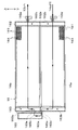
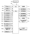
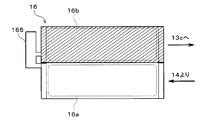
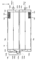
- 1 is an overall configuration diagram of a vehicle air conditioner according to a first embodiment. It is a typical sectional view of the outdoor heat exchanger of a 1st embodiment. It is a typical sectional view of the accumulator of a 1st embodiment. It is a block diagram which shows the electric control part of the vehicle air conditioner of 1st Embodiment. It is a flowchart which shows the control processing at the time of the cooling mode of 1st Embodiment. It is explanatory drawing which represented typically the state inside the outdoor heat exchanger at the time of the 1st cooling mode of 1st Embodiment.
- FIG. 4 is an explanatory diagram illustrating a relationship between a throttle opening degree of the expansion valve for cooling according to the first embodiment and a state of a refrigerant.
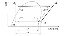
- FIG. 3 is a Mollier chart showing a change in a state of a refrigerant in a cooling mode according to the first embodiment. It is a typical sectional view of the outdoor heat exchanger of a 2nd embodiment.
- the refrigeration cycle device 10 according to the present disclosure is applied to the vehicle air conditioner 1.
- the vehicle air conditioner 1 includes a refrigeration cycle device 10, an indoor air conditioning unit 30, a high-temperature side heat medium circuit 40, and the like, as shown in the overall configuration diagram of FIG.
- the refrigeration cycle apparatus 10 has a function of cooling the blast air blown into the vehicle compartment and a high-temperature side heat medium circulating through the high-temperature side heat medium circuit 40 in the vehicle air conditioner 1 in order to perform air conditioning of the vehicle interior. Heat. Therefore, the fluid to be cooled in the refrigeration cycle device 10 is blast air.
- the refrigeration cycle apparatus 10 is further configured to be able to switch between a refrigerant circuit in a cooling mode, a refrigerant circuit in a series dehumidifying and heating mode, a refrigerant circuit in a parallel dehumidifying and heating mode, and a refrigerant circuit in a heating mode.
- the cooling mode is an operation mode in which the air in the vehicle compartment is cooled by cooling the blown air and blowing it out into the vehicle compartment.
- the in-line dehumidification and heating mode is an operation mode in which the cooled and dehumidified blast air is reheated and blown out into the vehicle interior to perform dehumidification and heating in the vehicle interior.
- the parallel dehumidifying and heating mode is an operation mode in which the cooled and dehumidified blast air is reheated with a higher heating capacity than the serial dehumidifying and heating mode and is blown out into the vehicle interior to perform dehumidification and heating in the vehicle interior.
- the heating mode is an operation mode for heating the vehicle interior by heating the blown air and blowing the air into the vehicle interior.
- the refrigeration cycle apparatus 10 can execute the operation of the first cooling mode and the second cooling mode as the cooling mode.
- the first cooling mode is a first cooling mode for cooling the blast air with a normal cooling capacity.
- the second cooling mode is a second cooling mode for cooling the blown air with a higher cooling capacity than the first cooling mode.
- the refrigeration cycle apparatus 10 employs an HFO-based refrigerant (specifically, R1234yf) as the refrigerant, and is a vapor compression type in which the pressure of the refrigerant discharged from the compressor 11 does not exceed the critical pressure of the refrigerant. Constructs a subcritical refrigeration cycle. Further, the refrigerant contains refrigeration oil for lubricating the compressor 11. Part of the refrigerating machine oil circulates through the cycle together with the refrigerant.
- HFO-based refrigerant specifically, R1234yf
- the compressor 11 sucks, compresses, and discharges the refrigerant in the refrigeration cycle device 10.
- the compressor 11 is arranged in a vehicle hood.
- the compressor 11 is an electric compressor in which a fixed displacement compression mechanism having a fixed discharge capacity is rotationally driven by an electric motor.
- the rotation speed (that is, the refrigerant discharge capacity) of the compressor 11 is controlled by a control signal output from a control device 60 described later.
- the inlet of the refrigerant passage of the water-refrigerant heat exchanger 12 is connected to the outlet of the compressor 11.
- the water-refrigerant heat exchanger 12 has a refrigerant passage through which the high-pressure refrigerant discharged from the compressor 11 flows, and a water passage through which the high-temperature heat medium circulating in the high-temperature heat medium circuit 40 flows.
- the water-refrigerant heat exchanger 12 is a heating heat exchanger that heats the high-temperature heat medium by exchanging heat between the high-pressure refrigerant flowing through the refrigerant passage and the high-temperature heat medium flowing through the water passage.
- the outlet of the coolant passage of the water-refrigerant heat exchanger 12 is connected to the inlet of a first three-way joint 13a having three inflow ports that communicate with each other.
- a three-way joint one formed by joining a plurality of pipes or one formed by providing a plurality of refrigerant passages in a metal block or a resin block can be adopted.
- the refrigeration cycle device 10 includes a second three-way joint 13b to a fourth three-way joint 13d.
- the basic configuration of the second to fourth three-way joints 13b to 13d is the same as that of the first three-way joint 13a.
- first three-way joint 13a to the fourth three-way joint 13d use one of the three inlets and outlets as an inlet, and use two of them as outlets, a branching part for branching the flow of the refrigerant is provided. Become. When two of the three inlets and outlets are used as inlets and one is used as an outlet, it serves as a merging portion for merging the flows of the refrigerant.
- An inlet of the heating expansion valve 14a is connected to one of the outlets of the first three-way joint 13a.
- One of the inlets of the second three-way joint 13b is connected to the other outlet of the first three-way joint 13a via a bypass passage 22a.
- An on-off valve 15a for dehumidification is arranged in the bypass passage 22a.
- the dehumidifying on-off valve 15a is an electromagnetic valve that opens and closes the bypass passage 22a. Further, the refrigeration cycle device 10 includes a heating on-off valve 15b as described later. The basic configuration of the heating on-off valve 15b is the same as that of the dehumidifying on-off valve 15a.
- the on-off valve 15a for dehumidification and the on-off valve 15b for heating can switch the refrigerant circuit of each operation mode by opening and closing the refrigerant passage. Therefore, the on-off valve 15a for dehumidification and the on-off valve 15b for heating are refrigerant circuit switching units that switch the refrigerant circuit of the cycle. The operations of the dehumidifying on-off valve 15a and the heating on-off valve 15b are controlled by a control voltage output from the control device 60.
- the heating expansion valve 14a depressurizes the high-pressure refrigerant flowing out of the refrigerant passage of the water-refrigerant heat exchanger 12 at least in a heating mode in which the vehicle interior is heated, and the flow rate (mass flow rate) of the refrigerant flowing downstream.
- the heating expansion valve 14a is an electric variable throttle mechanism that includes a valve body configured to change the opening degree of the throttle and an electric actuator that changes the opening degree of the valve body.
- the refrigeration cycle device 10 includes a cooling expansion valve 14b, as described later.
- the basic configuration of the cooling expansion valve 14b is the same as that of the heating expansion valve 14a.
- the heating expansion valve 14a and the cooling expansion valve 14b have a fully open function that functions as a mere refrigerant passage without exerting a flow rate adjusting action and a refrigerant pressure reducing action by fully opening the valve opening degree, and a full valve opening degree. It has a fully closed function of closing the refrigerant passage by closing.
- the heating expansion valve 14a and the cooling expansion valve 14b can switch the refrigerant circuit in each operation mode by the fully open function and the fully closed function. Therefore, the heating expansion valve 14a and the cooling expansion valve 14b also have a function as a refrigerant circuit switching unit.
- the operation of the heating expansion valve 14a and the cooling expansion valve 14b is controlled by a control signal (control pulse) output from the control device 60.
- the refrigerant inflow port 162d side of the outdoor heat exchanger 16 is connected to the outlet of the heating expansion valve 14a.
- the outdoor heat exchanger 16 is a heat exchanger that exchanges heat between the refrigerant flowing out of the heating expansion valve 14a and the outside air blown by a cooling fan (not shown).
- the outdoor heat exchanger 16 is arranged on the front side inside the vehicle hood. For this reason, when the vehicle is traveling, traveling wind can be applied to the outdoor heat exchanger 16.
- the outdoor heat exchanger 16 of the present embodiment has a so-called tank-and-tube type heat exchanger structure.
- the outdoor heat exchanger 16 includes a plurality of tubes 161, a pair of tanks 162 and 163, a corrugated fin 164, a modulator 165, and the like. Each of these constituent members is formed of the same kind of metal (in this embodiment, an aluminum alloy) having excellent heat conductivity.
- the components of the outdoor heat exchanger 16 are integrated by brazing.
- the plurality of tubes 161 are tubular members through which a refrigerant flows.
- the tube 161 is a flat tube having a flat cross section.
- the tube 161 is formed in a shape extending in the horizontal direction.
- Each of the tubes 161 is vertically stacked at regular intervals so that the flat surfaces (so-called flat surfaces) of the outer surfaces are parallel to each other.
- forty tubes 161 are stacked and arranged.
- the corrugated fin 164 is a heat exchange fin that is disposed in an air passage formed between the adjacent tubes 161 and that promotes heat exchange between the refrigerant and the outside air.
- FIG. 2 for clarification of illustration, only a part of the tube 161 and the corrugated fin 164 are shown, but the tube 161 and the corrugated fin 164 are arranged over the entire area of the heat exchange unit. .
- the pair of tanks 162 and 163 are respectively connected to both ends of the tube 161. Inside the pair of tanks 162 and 163, a distribution space for distributing the refrigerant to the plurality of tubes 161 or a collecting space for collecting the refrigerant flowing out of the plurality of tubes 161 is formed.
- the plurality of tubes 161 are divided into a plurality of (two in the present embodiment) paths.
- the path in the tank-and-tube type heat exchanger means that the refrigerant in the same distribution space formed in one tank is directed in the same direction toward the same collective space formed in the other tank. It can be defined as a refrigerant flow path formed by a group of tubes flowing to the flow path.
- the separator 162a is disposed at the center in the vertical direction of one of the tanks 162. For this reason, the internal space of one tank 162 is partitioned into two spaces having substantially the same volume in the vertical direction. Further, a separator 163a is arranged at the center in the vertical direction of the other tank 163. For this reason, the internal space of the other tank 163 is partitioned into two spaces having substantially the same volume in the vertical direction.
- a refrigerant inflow port 162d through which the refrigerant flowing out of the heating expansion valve 14a flows is connected to a portion forming a space below the one tank 162. Therefore, the lower space in one tank 162 supplies the refrigerant to a plurality of (specifically, 20) tubes 161 connected to a portion of the one tank 162 that forms the lower space. It becomes the first distribution space 162b for distribution.
- the space below the other tank 163 collects the refrigerant flowing out from a plurality of (specifically, 20) tubes 161 connected to a portion forming the space below the other tank 163. It becomes the first set space 163b to be made. Then, a first path is formed by a group of tubes through which the refrigerant flows from the first distribution space 162b to the first collection space 163b.
- a refrigerant outlet port 162e that allows the refrigerant to flow toward the inlet side of the third three-way joint 13c is connected to a portion forming a space above the one tank 162. Therefore, the space above one tank 162 collects the refrigerant flowing out from a plurality of (specifically, 20) tubes 161 connected to a portion of the one tank 162 that forms the space above. The second set space 162c is obtained.
- the space above the other tank 163 distributes the refrigerant to a plurality of (specifically, 20) tubes 161 connected to a portion forming the space above the other tank 163.
- pass is formed by the tube group which flows a refrigerant
- a coolant outlet 163d for allowing the coolant to flow out of the first collecting space 163b is formed in a portion of the other tank 163 where the first collecting space 163b is formed.
- the refrigerant outlet 163d is arranged on the uppermost side of a portion of the other tank 163 where the first collecting space 163b is formed.
- the refrigerant outlet 163d is connected to the refrigerant inlet 165a side of the modulator section 165.
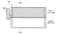
- the modulator 165 separates the gas-liquid of the high-pressure refrigerant that has exchanged heat with the outside air when flowing through the first path, and stores the separated high-pressure liquid-phase refrigerant as surplus refrigerant in the cycle. It is a side liquid storage part.
- the modulator section 165 is formed in a bottomed cylindrical shape whose central axis extends in the stacking direction of the plurality of tubes 161 (that is, in the up-down direction).
- the refrigerant inlet 165a of the modulator section 165 is disposed on the lowermost side of the modulator section 165.
- the refrigerant outlet 165b of the modulator 165 is connected to the refrigerant inlet 163e formed in the other tank 163.
- the refrigerant inlet 163e is formed in a portion of the other tank 163 that forms the second distribution space 163c. Further, the refrigerant inlet 163e is positioned on the lower side so that the refrigerant flowing from the modulator section 165 into the second distribution space 163c has a velocity component from the lower side to the upper side.
- the heat exchange section 16a is configured.
- the plurality of tubes 161 constituting the second path constitute a second heat exchange section 16b for exchanging heat between the refrigerant flowing out of the modulator section 165 and the outside air.
- the first heat exchange unit 16a is disposed below the second heat exchange unit 16b in the vertical direction. Further, the number of tubes 161 constituting the first pass is the same as the number of tubes 161 constituting the second pass. Therefore, the heat exchange area for exchanging heat between the refrigerant and the outside air in the first heat exchange section 16a is equal to the heat exchange area for exchanging heat between the refrigerant and the outside air in the second heat exchange section 16b.
- the refrigerant outlet 163d is arranged on the uppermost side of the first heat exchange part 16a means that the refrigerant outlet 163d is opened only at the uppermost part in the vertical direction of the member constituting the first heat exchange part 16a. It is not limited to the meaning that it is.
- the refrigerant outlet 163d is opened so as to include the uppermost part in the vertical direction or a position slightly lower than the uppermost part in the vertical direction of the member constituting the first heat exchange unit 16a, and is substantially opened at the uppermost part. It is a meaning including.
- the refrigerant inlet 165a of the modulator part 165 is arranged at the lowermost side of the modulator part 165 is limited to the meaning that the refrigerant inlet 165a is opened only at the lowermost part of the modulator part 165 in the vertical direction. Not done. This means that the refrigerant inlet 165a is opened so as to include the lowermost portion of the modulator portion 165 in the vertical direction or a position slightly lower than the lowermost portion in the vertical direction, and substantially opens at the lowermost portion.
- the inflow port side of the third three-way joint 13c is connected to the refrigerant outflow port 162e of the outdoor heat exchanger 16.
- One of the outlets of the third three-way joint 13c is connected to one of the inlets of the fourth three-way joint 13d via a heating passage 22b.
- a heating opening / closing valve 15b that opens and closes the refrigerant passage is arranged in the heating passage 22b.
- the other inflow side of the second three-way joint 13b is connected to the other outflow port of the third three-way joint 13c.
- a check valve 17 is arranged in the refrigerant passage connecting the other outlet side of the third three-way joint 13c and the other inlet side of the second three-way joint 13b. The check valve 17 allows the refrigerant to flow from the third three-way joint 13c to the second three-way joint 13b, and prohibits the refrigerant from flowing from the second three-way joint 13b to the third three-way joint 13c.
- the inlet of the cooling expansion valve 14b is connected to the outlet of the second three-way joint 13b.
- the cooling expansion valve 14b is a pressure reducing unit that reduces the pressure of the refrigerant flowing out of the outdoor heat exchanger 16 and adjusts the flow rate of the refrigerant flowing downstream at least in the cooling mode.
- the refrigerant inlet side of the indoor evaporator 18 is connected to the outlet of the cooling expansion valve 14b.
- the indoor evaporator 18 is arranged in an air-conditioning case 31 of an indoor air-conditioning unit 30 described later.
- the indoor evaporator 18 blows air by exchanging heat between the low-pressure refrigerant depressurized by the cooling expansion valve 14b and the blast air blown from the blower 32 to evaporate the low-pressure refrigerant and exert an endothermic effect on the low-pressure refrigerant.
- This is a cooling heat exchanger that cools air.
- the refrigerant outlet of the indoor evaporator 18 is connected to the inlet side of the evaporation pressure regulating valve 20.
- the evaporation pressure regulating valve 20 maintains the refrigerant evaporation pressure in the indoor evaporator 18 at or above a predetermined reference pressure in order to suppress frost formation on the indoor evaporator 18.
- the evaporating pressure adjusting valve 20 is configured by a mechanical variable throttle mechanism that increases the valve opening as the pressure of the refrigerant on the outlet side of the indoor evaporator 18 increases.
- the evaporation pressure regulating valve 20 maintains the refrigerant evaporation temperature in the indoor evaporator 18 at a frost formation suppression temperature (1 ° C. in the present embodiment) capable of suppressing frost formation on the indoor evaporator 18.
- the other inlet side of the fourth three-way joint 13d is connected to the outlet of the evaporation pressure regulating valve 20.
- the refrigerant outlet 212a side of the accumulator 21 is connected to the outlet of the fourth three-way joint 13d.
- the accumulator 21 is a low-pressure storage unit that separates gas-liquid refrigerant flowing out of the indoor evaporator 18 in a cooling mode or the like and stores the separated low-pressure liquid-phase refrigerant as surplus refrigerant in the cycle.
- the suction port side of the compressor 11 is connected to the gas-phase refrigerant outlet 213b of the accumulator 21.
- the accumulator 21 has a refrigerant container 211, an inlet pipe 212, an outlet pipe 213, and the like.
- the refrigerant container 211 is made of metal (in this embodiment, aluminum) formed in a bottomed cylindrical shape.
- the refrigerant container 211 is arranged so that its central axis extends in the vertical direction.
- a storage space for separating gas-liquid of the refrigerant and storing the separated liquid-phase refrigerant is formed inside the refrigerant container 211.
- the inlet pipe 212 is a piping member formed of the same metal as the refrigerant container 211.
- the inlet-side pipe 212 is formed in a shape extending in the up-down direction.
- One end of the inlet-side pipe 212 is disposed above the refrigerant container 211 and forms a refrigerant inlet 212a through which the refrigerant flowing out of the fourth three-way joint 13d flows.
- the other end of the inlet-side pipe 212 is disposed inside the refrigerant container 211 and forms a refrigerant outlet 212b.
- the outlet-side pipe 213 is a piping member formed of the same metal as the refrigerant container 211.
- the outlet side pipe 213 is formed in a shape having a U-shaped curved portion.
- One end of the outlet pipe 213 is arranged above the outside of the refrigerant container 211 to form a gas-phase refrigerant outlet 213b that allows the gas-phase refrigerant to flow toward the suction port of the compressor 11.
- the other end of the outlet-side pipe 213 is disposed inside the refrigerant container 211 and forms a gas-phase refrigerant inlet 213a through which the gas-phase refrigerant separated inside the refrigerant container 211 flows.
- the gas-phase refrigerant inlet 213 a is above the liquid surface and further above the refrigerant outlet 212 b of the inlet pipe 212. Are located in Therefore, the liquid-phase refrigerant does not flow into the outlet-side pipe 213 from the gas-phase refrigerant inlet 213a.
- the curved portion of the outlet-side pipe 213 is disposed below the liquid surface.
- An oil return hole 213c is formed at the lowermost portion of the curved portion.
- the oil return hole 213c is a hole formed for sucking the liquid-phase refrigerant in which the refrigerating machine oil is dissolved and sucking the liquid-phase refrigerant into the compressor 11 when the liquid-phase refrigerant is stored in the accumulator 21.
- the high-temperature-side heat medium circuit 40 is a heat medium circulation circuit that circulates the high-temperature-side heat medium.
- the high-temperature side heat medium ethylene glycol, dimethylpolysiloxane, a solution containing a nanofluid, or the like, an antifreeze, or the like can be used.
- the high-temperature heat medium circuit 40 includes a water passage of the water-refrigerant heat exchanger 12, a high-temperature heat medium pump 41, a heater core 42, and the like.
- the high-temperature heat medium pump 41 is a water pump for pumping the high-temperature heat medium to the inlet side of the water passage of the water-refrigerant heat exchanger 12.
- the high-temperature-side heat medium pump 41 is an electric pump whose rotation speed (that is, pumping capacity) is controlled by a control voltage output from the control device 60.
- the outlet of the water passage of the water-refrigerant heat exchanger 12 is connected to the heat medium inlet side of the heater core 42.
- the heater core 42 is a heat exchanger that heats the blown air by exchanging heat between the high-temperature side heat medium heated by the water-refrigerant heat exchanger 12 and the blown air that has passed through the indoor evaporator 18.
- the heater core 42 is arranged inside the air conditioning case 31 of the indoor air conditioning unit 30.
- the heat medium outlet of the heater core 42 is connected to the suction side of the high-temperature side heat medium pump 41.
- each component of the water-refrigerant heat exchanger 12 and the high-temperature side heat medium circuit 40 constitutes a heating unit that heats the blown air using the refrigerant discharged from the compressor 11 as a heat source. I have.
- the indoor air-conditioning unit 30 is for blowing blast air adjusted to an appropriate temperature for air-conditioning the vehicle interior to an appropriate location in the vehicle interior.
- the indoor air-conditioning unit 30 is arranged inside the instrument panel (instrument panel) at the forefront of the vehicle interior.
- the indoor air-conditioning unit 30 has a blower 32, an indoor evaporator 18, a heater core 42, and the like housed in an air-conditioning case 31 that forms an air passage for blowing air.
- the air-conditioning case 31 has a certain degree of elasticity and is formed of a resin (for example, polypropylene) having excellent strength.
- An inside / outside air switching device 33 is disposed on the most upstream side of the airflow of the air conditioning case 31.
- the inside / outside air switching device 33 switches and introduces inside air (vehicle interior air) and outside air (vehicle outside air) into the air conditioning case 31.
- the operation of the electric actuator for driving the inside / outside air switching device 33 is controlled by a control signal output from the control device 60.
- a blower 32 is disposed downstream of the inside / outside air switching device 33 in the blown air flow.
- the blower 32 blows the air taken in through the inside / outside air switching device 33 toward the vehicle interior.
- the blower 32 is an electric blower that drives a centrifugal multi-blade fan with an electric motor.
- the rotation speed (that is, the blowing capacity) of the blower 32 is controlled by the control voltage output from the control device 60.
- the indoor evaporator 18 and the heater core 42 are arranged in this order with respect to the blown air flow. That is, the indoor evaporator 18 is arranged on the upstream side of the flow of the blown air from the heater core 42.
- a cool air bypass passage 35 is provided in the air-conditioning case 31 to allow the air blown through the indoor evaporator 18 to flow around the heater core 42. Further, an air mix door 34 is arranged on the downstream side of the air flow of the indoor evaporator 18 in the air conditioning case 31 and on the upstream side of the air flow of the heater core 42.
- the air mix door 34 adjusts a flow rate ratio of a flow rate of the blown air passing through the heater core 42 and a flow rate of the blown air passing through the cool air bypass passage 35 among the blown air after passing through the indoor evaporator 18. Department.
- the operation of the electric actuator for driving the air mix door 34 is controlled by a control signal output from the control device 60.
- the mixing space is disposed downstream of the air flow of the heater core 42 and the cool air bypass passage 35 in the air conditioning case 31.
- the mixing space is a space for mixing the blast air heated by the heater core 42 and the blast air that has not passed through the cool air bypass passage 35 and is not heated. Further, an opening hole for blowing out the blown air mixed and temperature-adjusted in the mixing space into the vehicle compartment is disposed downstream of the airflow of the air-conditioning case 31.
- the face opening hole is an opening hole for blowing out conditioned air toward the upper body of the occupant in the passenger compartment.
- the foot opening hole is an opening hole for blowing out conditioned air toward the feet of the occupant.
- the defroster opening hole is an opening hole for blowing out conditioned air toward the inner surface of the vehicle front window glass.
- the temperature of the conditioned air mixed in the mixing space is adjusted by adjusting the air flow ratio of the air flow passing through the heater core 42 and the air flow passing through the cool air bypass passage 35 by the air mixing door 34. Then, the temperature of the blown air (conditioned air) blown out from each outlet into the vehicle interior is adjusted.
- Face doors, foot doors, and defroster doors are arranged on the upstream side of the airflow from the face opening, the foot opening, and the defroster opening.
- the face door, the foot door, and the defroster door are opening / closing units that open and close corresponding opening holes according to the operation mode.
- the control device 60 includes a well-known microcomputer including a CPU, a ROM, a RAM, and the like, and its peripheral circuits. Then, various calculations and processes are performed based on the air conditioning control program stored in the ROM, and the operations of the various control target devices 11, 14a, 14b, 15a, 15b, 32, 41, etc. connected to the output side are performed. Control.
- an inside air temperature sensor 61 On the input side of the control device 60, as shown in the block diagram of FIG. 4, an inside air temperature sensor 61, an outside air temperature sensor 62, a solar radiation sensor 63, first to fourth refrigerant temperature sensors 64a to 64d, and evaporation.
- the control unit 60 receives detection signals from these sensor groups.
- the inside air temperature sensor 61 is an inside air temperature detection unit that detects the vehicle interior temperature (inside air temperature) Tr.
- the outside air temperature sensor 62 is an outside air temperature detection unit that detects a vehicle outside temperature (outside air temperature) Tam.
- the solar radiation sensor 63 is a solar radiation amount detecting unit that detects a solar radiation amount Ts irradiated into the vehicle interior.
- the first refrigerant temperature sensor 64a is a discharged refrigerant temperature detection unit that detects the temperature T1 of the refrigerant discharged from the compressor 11.
- the second refrigerant temperature sensor 64b is a second refrigerant temperature detector that detects the temperature T2 of the refrigerant flowing out of the refrigerant passage of the water-refrigerant heat exchanger 12.
- the third refrigerant temperature sensor 64c is a third refrigerant temperature detection unit that detects the temperature T3 of the refrigerant flowing out of the outdoor heat exchanger 16.
- the fourth refrigerant temperature sensor 64d is a fourth refrigerant temperature detector that detects the temperature T4 of the refrigerant flowing out of the indoor evaporator 18.
- the evaporator temperature sensor 64f is an evaporator temperature detection unit that detects the refrigerant evaporation temperature (evaporator temperature) Tefin in the indoor evaporator 18.
- the evaporator temperature sensor 64f of this embodiment specifically detects the temperature of the heat exchange fins of the indoor evaporator 18.
- the first refrigerant pressure sensor 65a is a first refrigerant pressure detector that detects the pressure P1 of the refrigerant flowing out of the refrigerant passage of the water-refrigerant heat exchanger 12.
- the second refrigerant pressure sensor 65b is a second refrigerant pressure detector that detects the pressure P2 of the refrigerant flowing out of the indoor evaporator 18.
- the high-temperature heat medium temperature sensor 66a is a high-temperature heat medium temperature detection unit that detects the high-temperature heat medium temperature TWH, which is the temperature of the high-temperature heat medium flowing out of the water passage of the water-refrigerant heat exchanger 12.
- the air-conditioning air temperature sensor 69 is an air-conditioning air temperature detecting unit that detects the temperature of the air blown from the mixing space into the vehicle compartment TAV.
- an operation panel 70 arranged near the instrument panel in the front of the vehicle compartment is connected to the input side of the control device 60, and various operation switches provided on the operation panel 70 An operation signal is input.
- Specific examples of various operation switches provided on the operation panel 70 include an auto switch, an air conditioner switch, an air volume setting switch, a temperature setting switch, a blowout mode switching switch, and the like.
- the automatic switch is an automatic control operation setting unit that sets or cancels the automatic control operation of the vehicle air conditioner 1.
- the air conditioner switch is a cooling request unit that requests the indoor evaporator 18 to cool the blown air.
- the air volume setting switch is an air volume setting unit for manually setting the air volume of the blower 32.
- the temperature setting switch is a target temperature setting unit that sets a target temperature Tset in the vehicle compartment.
- the blowout mode is a blowout mode switching setting unit for manually setting the blowout mode.
- the control device 60 of the present embodiment has an integrated control unit for controlling various control target devices connected to the output side. Therefore, the configuration (hardware and software) that controls the operation of each control target device constitutes a control unit that controls the operation of each control target device.
- the configuration that controls the refrigerant discharge capacity of the compressor 11 constitutes the discharge capacity control unit 60a.
- the configuration for controlling the operation of the cooling expansion valve 14b forms the pressure reducing control unit 60b.
- the vehicle air conditioner 1 of the present embodiment can perform cooling, dehumidifying heating, and heating of the vehicle interior. Further, the refrigeration cycle apparatus 10 switches the operation among a cooling mode, a series dehumidifying and heating mode, a parallel dehumidifying and heating mode, and a heating mode for air conditioning in the vehicle compartment.
- the switching of each operation mode of the refrigeration cycle device 10 is performed by executing an air conditioning control program.
- the air conditioning control program is executed when the automatic switch of the operation panel 70 is turned on (ON) and the automatic control operation is set.
- a target outlet temperature TAO which is a target temperature of the outlet air to be blown into the vehicle interior
- the target outlet temperature TAO is calculated by the following equation F1.
- TAO Kset ⁇ Tset ⁇ Kr ⁇ Tr ⁇ Kam ⁇ Tam ⁇ Ks ⁇ As + C (F1)
- Tset is a target temperature in the vehicle interior (vehicle interior setting temperature) set by the temperature setting switch
- Tr is the internal air temperature detected by the internal air temperature sensor 61
- Tam is the external air temperature detected by the external air temperature sensor 62
- Ts Is the amount of solar radiation detected by the solar radiation sensor 63.
- Kset, Kr, Kam, and Ks are control gains
- C is a correction constant.
- the target outlet temperature TAO is equal to or higher than the cooling reference temperature ⁇
- the outside air temperature Tam is higher than the predetermined dehumidifying heating reference temperature ⁇ .
- the operation mode is switched to the in-line dehumidification heating mode.
- the operation mode is switched to the parallel dehumidification heating mode.
- the cooling mode is mainly executed when the outside air temperature is relatively high, such as in summer.
- the in-line dehumidification heating mode is mainly performed in the spring or autumn.
- the parallel dehumidifying and heating mode is mainly executed when it is necessary to heat the blown air with a higher heating capacity than in the series dehumidifying and heating mode, such as early spring or late autumn.
- the heating mode is mainly executed at a low outside air temperature in winter. The operation in each operation mode will be described below.
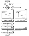
- the switching between the first cooling mode and the second cooling mode is performed by executing the control flow shown in FIG.
- the control flow shown in FIG. 5 is executed as a subroutine of the main routine of the air conditioning control program.
- the control flow shown in FIG. 5 is executed at predetermined intervals when the cooling mode is selected in the main routine. Details of the control flow in FIG. 5 will be described later.
- the control device 60 causes the heating expansion valve 14a to be in a fully open state and the cooling expansion valve 14b to be in a throttled state in which a decompression effect is exerted. Further, the control device 60 closes the dehumidifying on-off valve 15a and closes the heating on-off valve 15b.
- the discharge port of the compressor 11, the water-refrigerant heat exchanger 12 (the heating expansion valve 14a), the outdoor heat exchanger 16, the check valve 17, and the cooling expansion valve 14b A vapor compression refrigeration cycle in which the refrigerant circulates in the order of the indoor evaporator 18, the evaporating pressure regulating valve 20, the accumulator 21, and the suction port of the compressor 11 is configured.
- control device 60 appropriately determines control signals and the like to be output to various control target devices connected to the output side, and outputs the determined control signals and the like to various control target devices.
- control device 60 determines a control signal for adjusting the rotation speed Nc of the compressor 11 so that the evaporator temperature Tefin detected by the evaporator temperature sensor 64f approaches the target evaporator temperature TEO.
- the target evaporator temperature TEO is determined based on the target outlet temperature TAO with reference to a cooling mode control map stored in the control device 60 in advance.
- the target evaporator temperature TEO is determined to increase as the target outlet temperature TAO increases. Further, the target evaporator temperature TEO is determined to a value within a range (specifically, 1 ° C. or more) in which frost formation on the indoor evaporator 18 can be suppressed.
- the control device 60 determines the control voltage to be output to the high-temperature side heat transfer medium pump 41 so as to exhibit a predetermined hydraulic pumping capacity for the cooling mode.
- control device 60 controls the output to the electric actuator for the air mixing door based on the target blowing temperature TAO, the evaporator temperature Tefin, and the high-temperature heat medium temperature TWH detected by the high-temperature heat medium temperature sensor 66a. Determine the signal. This control signal is determined such that the temperature of the blown air blown into the vehicle compartment approaches the target blowout temperature TAO.
- a refrigeration cycle in which the water-refrigerant heat exchanger 12 and the outdoor heat exchanger 16 function as a condenser and the indoor evaporator 18 functions as an evaporator is configured. Therefore, in the cooling mode, the inside of the vehicle compartment can be cooled by blowing the air cooled by the indoor evaporator 18 to the heater core 42 and blowing it out into the vehicle compartment.
- step S10 it is determined whether or not the evaporator temperature Tefin has reached the target evaporator temperature TEO.
- step S10 If it is determined in step S10 that the evaporator temperature Tefin has reached the target evaporator temperature TEO, the process proceeds to step S30, and the control of the first cooling mode shown in steps S30 to S50 is performed. If it is determined in step S10 that the evaporator temperature Tefin is not at the target evaporator temperature TEO, that is, if the evaporator temperature Tefin is higher than the target evaporator temperature TEO, the process proceeds to step S20. .
- step S20 it is determined whether or not the rotation speed Nc of the compressor 11 has reached the maximum rotation speed NcMax.
- the maximum rotation speed NcMax a maximum rotation speed determined from the durability performance of the compressor 11 or a maximum rotation speed determined for noise suppression or the like in accordance with operating conditions can be adopted.
- step S20 If it is determined in step S20 that the rotation speed Nc of the compressor 11 has reached the maximum rotation speed NcMax, the process proceeds to step S100, and the operation in the second cooling mode shown in steps S100 to S140 is performed.
- step S20 when it is determined that the rotation speed Nc of the compressor 11 has not reached the maximum rotation speed NcMax, that is, it is determined that the rotation speed Nc of the compressor 11 has not reached the maximum rotation speed NcMax. In this case, the process proceeds to step S30, and the operation in the first cooling mode is performed.
- a target supercooling degree SCO1 for the first cooling mode is determined as a target value of the supercooling degree SC of the refrigerant flowing out of the outdoor heat exchanger 16 and flowing into the cooling expansion valve 14b, and step S40 is performed. Proceed to.
- the target degree of supercooling SCO1 is determined with reference to a control map shown in the control characteristic diagram of step S30 in FIG. In this control map, the target degree of supercooling SCO1 is determined based on the outside temperature Tam so that the coefficient of performance (COP) of the cycle approaches the maximum value.
- step S40 the change amount ⁇ EVC1 of the throttle opening of the cooling expansion valve 14b is determined so that the subcooling degree SC approaches the target subcooling degree SCO1, and the process proceeds to step S50.
- the degree of supercooling SC is calculated using the temperature T3 detected by the third refrigerant temperature sensor 64c and the pressure P1 detected by the first refrigerant pressure sensor 65a.
- step S50 the amount of change ⁇ EVC in the throttle opening of the cooling expansion valve 14b is determined, and the process proceeds to step S60.
- step S50 the change amount ⁇ EVC1 determined in step S40 is adopted as the change amount ⁇ EVC.
- step S60 the change amount ⁇ EVC determined in step S70 is added to the previous throttle opening EVCn-1 of the cooling expansion valve 14b, and the current throttle opening EVCn is determined. Then, the control signal to be output to the cooling expansion valve 14b is determined so that the current throttle opening EVCn is obtained, and the process returns to the main routine.
- a target supercooling degree SCO2 for the second cooling mode is determined as a target value of the supercooling degree SC, and the process proceeds to step S110.
- the target degree of supercooling SCO2 is determined with reference to a control map shown in the control characteristic diagram of step S100 in FIG. In this control map, the target supercooling degree SCO2 is determined so as to be a value obtained by adding a predetermined amount (10 ° C. in the present embodiment) to the target supercooling degree SCO1 determined in step S30.
- step S110 the amount of change ⁇ EVC1 in the throttle opening of the cooling expansion valve 14b is determined so that the subcooling degree SC approaches the target subcooling degree SCO2, and the process proceeds to step S120.
- the target superheat degree SHO2 for the second cooling mode is determined as the target value of the superheat degree SH of the refrigerant on the outlet side of the indoor evaporator 18, and the process proceeds to Step S130.
- the target superheat degree SHO2 is determined to be 10 ° C.
- step S130 the amount of change ⁇ EVC2 in the throttle opening of the cooling expansion valve 14b is determined so that the superheat degree SH approaches the target superheat degree SHO2, and the process proceeds to step S140.
- step S140 the change amount ⁇ EVC of the throttle opening of the cooling expansion valve 14b is determined, and the process proceeds to step S60.
- step S140 the larger value of the change amount ⁇ EVC1 determined in step S110 and the change amount ⁇ EVC2 determined in step S130 is adopted as the change amount ⁇ EVC.
- the target supercooling degree SCO2 determined in step S100 is set to be a sufficiently high value. More specifically, even if the throttle opening of the cooling expansion valve 14b is determined so that the actual superheat degree SH becomes the target superheat degree SHO2, the actual supercooling degree SC does not reach the target supercooling degree SCO2. Is set to a high value.
- step S110 the variation ⁇ EVC1 determined in step S110 becomes a negative value in order to decrease the throttle opening of the cooling expansion valve 14b, and tends to be smaller than the variation ⁇ EVC2 determined in step S130. Therefore, in step S70 of the second cooling mode, the change amount ⁇ EVC2 is often adopted as the change amount ⁇ EVC.
- steps S30 and S100 are target supercooling degree determination units that determine the target supercooling degrees SCO1 and SCO2 of the refrigerant flowing into the cooling expansion valve 14b.
- Step S120 is a target superheat degree determination unit that determines the target superheat degree SHO2 of the refrigerant on the outlet side of the indoor evaporator 18.
- steps S10 and S20 it is assumed that the condition for determining that the cooling capacity of the blown air in the indoor evaporator 18 is insufficient is satisfied. That is, it is assumed that the cooling capacity shortage condition is satisfied. More specifically, when the evaporator temperature Tefin has not reached the target evaporator temperature TEO and the rotation speed Nc of the compressor 11 has reached the maximum rotation speed NcMax, the cooling capacity shortage condition has been satisfied. And
- FIGS. 6 to 8 schematically show the distribution of the liquid-phase refrigerant in the outdoor heat exchanger 16 in each operation mode, and the region where the liquid-phase refrigerant is distributed is schematically shown by hatching.
- I have.
- the throttle openings of the cooling expansion valve 14b in the states shown in FIGS. 6 to 8 are indicated by (A) to (C), respectively.
- a change in the state of the refrigerant in the first cooling mode is indicated by a broken line
- a change in the state of the refrigerant in the second cooling mode is indicated by a thick solid line.
- the throttle opening of the cooling expansion valve 14b is controlled such that the supercooling degree SC approaches the target supercooling degree SCO1.
- This throttle opening is indicated by the throttle opening (A) in FIG.
- a region on the upstream side of the refrigerant flow of the first heat exchange unit 16a and the second heat exchange unit 16b of the outdoor heat exchanger 16 is a condensing unit that condenses the refrigerant.
- a region on the downstream side of the refrigerant flow of the second heat exchange unit 16b is a subcooling unit that supercools the liquid-phase refrigerant. Therefore, the excess refrigerant of the cycle is stored in the accumulator 21 as shown by the liquid level H in the accumulator 21 in FIG.
- the compressor 11 sends the relatively high dryness gas-liquid two-phase containing the liquid-phase refrigerant in which the refrigerating machine oil is dissolved, from the accumulator 21.
- the refrigerant (point a1 in FIG. 10) is sucked and compressed.
- the refrigerant discharged from the compressor 11 flows into the outdoor heat exchanger 16 and exchanges heat with the outside air to radiate heat (points b1 to c1 in FIG. 10).
- the supercooling degree SC of the refrigerant (point c1 in FIG. 10) flowing out of the outdoor heat exchanger 16 approaches the target supercooling degree SCO1.
- the refrigerant flowing out of the outdoor heat exchanger 16 is decompressed by the cooling expansion valve 14b (point c1 to point d1 in FIG. 10).
- the refrigerant decompressed by the cooling expansion valve 14b absorbs heat from the blown air in the indoor evaporator 18 and evaporates (from point d1 to point a1 in FIG. 10). Thereby, the blown air is cooled.
- the refrigerant flowing out of the indoor evaporator 18 flows into the accumulator 21 and is separated into gas and liquid.
- the blast air is cooled so that the COP of the cycle becomes a maximum value.
- the target supercooling degree SCO2 determined to be higher than the target supercooling degree SCO1 is adopted as the target value of the supercooling degree SC. You. For this reason, in order to increase the degree of supercooling SC from the first cooling mode, the throttle opening of the cooling expansion valve 14b decreases. In FIG. 9, the throttle opening (A) decreases to the throttle opening (B).
- the first heat exchange section 16a of the outdoor heat exchanger 16 becomes a condenser section. Further, the entire area of the second heat exchange section 16b is filled with the high-pressure liquid-phase refrigerant to become a supercooling section.
- the surplus refrigerant stored in the accumulator 21 is smaller than in the first cooling mode. That is, the liquid level H decreases. Further, the refrigerant condensation pressure in the outdoor heat exchanger 16 increases. Furthermore, since the target degree of supercooling SCO2 is set to a value sufficiently higher than the target degree of supercooling SCO1, the actual degree of supercooling SC has not reached the target degree of supercooling SCO2.
- the throttle opening of the cooling expansion valve 14b further decreases.
- the throttle opening (B) decreases to the throttle opening (C).
- the inside of the modulator 165 is also filled with the high-pressure liquid-phase refrigerant. That is, the surplus refrigerant of the cycle stored in the accumulator 21 moves into the modulator section 165.
- the superheat degree SH of the refrigerant in the accumulator 21 and the refrigerant on the outlet side of the indoor evaporator 18 increases to the target superheat degree SHO2 (specifically, 10 ° C.).
- the compressor 11 sucks the gaseous refrigerant having the degree of superheat (point a2 in FIG. 10) from the accumulator 21 and compresses it, as indicated by the thick solid line in the Mollier diagram in FIG. I do.
- the refrigerant discharged from the compressor 11 exchanges heat with the outside air and radiates heat in the outdoor heat exchanger 16 (point b2 to point c2 in FIG. 10). Then, the excess refrigerant of the cycle becomes high-pressure liquid-phase refrigerant and is stored in the modulator section 165.
- the refrigerant flowing out of the outdoor heat exchanger 16 is decompressed by the cooling expansion valve 14b (from point c2 to point d2 in FIG. 10).
- the refrigerant decompressed by the cooling expansion valve 14b absorbs heat from the blown air in the indoor evaporator 18 and evaporates (from point d2 to point a2 in FIG. 10). Thereby, the blown air is cooled.
- the degree of superheat SH of the refrigerant on the outlet side of the indoor evaporator 18 approaches the target degree of superheat SHO2.
- the superheated refrigerant flowing out of the indoor evaporator 18 flows into the accumulator 21.
- the enthalpy difference ⁇ ie2 obtained by subtracting the enthalpy of the refrigerant on the inlet side of the indoor evaporator 18 from the enthalpy of the refrigerant on the outlet side of the indoor evaporator 18 is equal to that in the first cooling mode. Is larger than the enthalpy difference ⁇ ie1. That is, the refrigeration cycle device 10 in the second cooling mode can cool the blown air with a higher cooling capacity than in the first cooling mode.
- (B) In-line dehumidification and heating mode In the in-series dehumidification and heating mode, the control device 60 sets the heating expansion valve 14a to the throttled state and sets the cooling expansion valve 14b to the throttled state. Further, the control device 60 closes the dehumidifying on-off valve 15a and closes the heating on-off valve 15b.
- the compressor 11 in the serial dehumidification heating mode, the compressor 11, the water-refrigerant heat exchanger 12, the heating expansion valve 14a, the outdoor heat exchanger 16, the check valve 17, the cooling expansion valve 14b, and the indoor evaporation
- a vapor compression refrigeration cycle in which the refrigerant circulates in the order of the device 18, the evaporation pressure regulating valve 20, the accumulator 21, and the compressor 11 is configured.
- control device 60 similarly to the cooling mode, the control device 60 appropriately determines control signals and the like output to various control target devices connected to the output side, and sends the determined control signals and the like to the various control target devices. Output.
- control device 60 transmits a control signal output to the heating expansion valve 14a and the cooling expansion valve 14b such that the blast air temperature TAV detected by the conditioned air temperature sensor 69 approaches the target outlet temperature TAO. decide. Therefore, in the series dehumidification heating mode, the surplus refrigerant of the cycle is stored in the accumulator 21.
- control device 60 controls the control signal so as to decrease the throttle opening of the heating expansion valve 14a and increase the throttle opening of the cooling expansion valve 14b as the target outlet temperature TAO increases. To determine.
- a refrigeration cycle in which the water-refrigerant heat exchanger 12 functions as a condenser and the indoor evaporator 18 functions as an evaporator is configured.
- the saturation temperature of the refrigerant in the outdoor heat exchanger 16 is higher than the outside air temperature Tam
- the saturation temperature of the refrigerant in the outdoor heat exchanger 16 is reduced with the rise of the target outlet temperature TAO, and the outdoor heat exchange is performed.
- the heat radiation amount of the refrigerant in the vessel 16 can be reduced.
- the heat radiation amount of the refrigerant in the water-refrigerant heat exchanger 12 can be increased, and the heating capability of the blower air in the heater core 42 can be improved.
- the saturation temperature of the refrigerant in the outdoor heat exchanger 16 is lower than the outside air temperature Tam
- the saturation temperature of the refrigerant in the outdoor heat exchanger 16 is reduced with an increase in the target outlet temperature TAO, and the outdoor heat exchange is performed.
- the amount of heat absorbed by the refrigerant in the vessel 16 can be increased.
- the heat radiation amount of the refrigerant in the water-refrigerant heat exchanger 12 can be increased, and the heating capability of the blower air in the heater core 42 can be improved.
- the air that has been cooled and dehumidified by the indoor evaporator 18 is reheated by the heater core 42 and blown out into the vehicle interior, whereby dehumidification and heating in the vehicle interior can be performed. Further, by adjusting the throttle openings of the heating expansion valve 14a and the cooling expansion valve 14b, the amount of refrigerant radiated in the water-refrigerant heat exchanger 12 is adjusted, and the heating capacity of the blower air in the heater core 42 is adjusted. can do.
- (C) Parallel dehumidification and heating mode In the parallel dehumidification and heating mode, the control device 60 sets the heating expansion valve 14a to a throttled state and sets the cooling expansion valve 14b to a throttled state. Further, the control device 60 opens the dehumidifying on-off valve 15a and opens the heating on-off valve 15b.
- the compressor 11, the water-refrigerant heat exchanger 12, the heating expansion valve 14a, the outdoor heat exchanger 16, the heating passage 22b (heating on-off valve 15b), A vapor compression refrigeration cycle in which the refrigerant circulates in the order of the accumulator 21 and the compressor 11 is configured.
- the compressor 11, the water-refrigerant heat exchanger 12, the bypass passage 22a (dehumidifying on-off valve 15a), the cooling expansion valve 14b, the indoor evaporator 18, the evaporation pressure regulating valve 20, the accumulator 21, and the compressor 11 in this order.
- a vapor compression refrigeration cycle in which the refrigerant circulates is configured. That is, a refrigeration cycle in which the outdoor heat exchanger 16 and the indoor evaporator 18 are connected in parallel to the refrigerant flow is configured.
- control device 60 appropriately determines control signals and the like to be output to various control target devices connected to the output side, and outputs the determined control signals and the like to various control target devices.
- control device 60 determines a control signal for controlling the rotation speed Nc of the compressor 11 such that the pressure P1 detected by the first refrigerant pressure sensor 65a approaches the target condensing pressure PDO.
- this control map it is determined that the target condensing pressure PDO increases as the target outlet temperature TAO increases.
- control device 60 determines a control signal to be output to heating expansion valve 14a and cooling expansion valve 14b such that COP approaches the maximum value. Therefore, in the parallel dehumidification heating mode, the surplus refrigerant of the cycle is stored in the accumulator 21.
- the blast air cooled and dehumidified by the indoor evaporator 18 is reheated by the heater core 42 and blown out into the vehicle interior, whereby dehumidification and heating in the vehicle interior can be performed.
- the evaporation temperature of the refrigerant in the outdoor heat exchanger 16 can be made lower than the evaporation temperature of the refrigerant in the indoor evaporator 18 without causing frost on the indoor evaporator 18 by the action of the evaporation pressure adjusting valve 20. it can.
- the amount of heat absorbed by the refrigerant in the outdoor heat exchanger 16 can be increased more than in the in-line dehumidifying and heating mode, and the heating capacity of the blown air can be increased.
- (D) Heating Mode In the heating mode, the control device 60 sets the heating expansion valve 14a to the throttled state and sets the cooling expansion valve 14b to the fully closed state. Further, the control device 60 closes the dehumidifying on-off valve 15a and opens the heating on-off valve 15b.
- control device 60 similarly to the parallel dehumidifying and heating mode, the control device 60 appropriately determines control signals and the like to be output to various control target devices connected to the output side, and determines the determined control signals and the like for various control targets. Output to device.
- control device 60 determines a control signal to be output to the heating expansion valve 14a such that the COP approaches the local maximum value, as in the first cooling mode. Therefore, in the heating mode, the surplus refrigerant of the cycle is stored in the accumulator 21.
- a refrigeration cycle is configured in which the water-refrigerant heat exchanger 12 functions as a condenser and the outdoor heat exchanger 16 functions as an evaporator. Therefore, in the heating mode, the inside of the vehicle compartment can be heated by blowing the blast air heated by the heater core 42 into the vehicle compartment.
- the operation of various operation modes can be performed by switching the refrigerant circuit.
- the vehicle air conditioner 1 comfortable air conditioning in the vehicle compartment can be realized.
- the refrigeration cycle device 10 of the present embodiment includes an accumulator 21 which is a low-pressure side liquid storage unit. Therefore, even if the heat exchanger functioning as a condenser changes according to the operation mode, the surplus refrigerant can be reliably stored in the accumulator 21.
- the outlet refrigerant of the indoor evaporator 18 approaches the saturated gas-phase refrigerant, so that the enthalpy difference ⁇ ie is increased by increasing the enthalpy of the outlet refrigerant of the indoor evaporator 18. It is difficult.
- the refrigerant drawn into the compressor 11 is a gas-liquid two-phase refrigerant having a high degree of dryness.
- the refrigerant on the outlet side of the indoor evaporator 18 becomes a gas-liquid two-phase refrigerant having a lower enthalpy than the saturated gas-phase refrigerant, and it is difficult to further increase the enthalpy difference ⁇ ie.
- Means for increasing the degree of supercooling of the refrigerant flowing out of the outdoor heat exchanger 16 in the first cooling mode and reducing the enthalpy of the refrigerant on the inlet side of the indoor evaporator 18 to increase the enthalpy difference ⁇ ie may be considered.
- the first cooling mode in which the excess refrigerant is stored in the accumulator 21 can be switched to the second cooling mode in which the excess refrigerant is stored in the modulator section 165.
- the refrigerant flowing out of the outdoor heat exchanger 16 does not needlessly increase the refrigerant condensation pressure in the outdoor heat exchanger 16.
- the degree of supercooling can be increased. That is, the enthalpy of the refrigerant on the inlet side of the indoor evaporator 18 can be reduced without unnecessarily increasing the refrigerant condensing pressure in the outdoor heat exchanger 16.
- the surplus refrigerant of the cycle is stored in the modulator unit 165, the low-pressure gas-phase refrigerant having a degree of superheat can flow into the accumulator 21. Therefore, the enthalpy of the refrigerant on the inlet side of the indoor evaporator 18 can be increased.
- the enthalpy difference ⁇ ie can be expanded more than in the first cooling mode, and the cooling capacity of the indoor evaporator 18 can be improved. That is, according to the refrigeration cycle device 10 of the present embodiment, the cooling capacity of the indoor evaporator 18 can be sufficiently improved.
- the target degree of supercooling is increased. According to this, when the cooling capacity of the blown air in the indoor evaporator 18 is insufficient, it is possible to surely shift from the first cooling mode to the second cooling mode and improve the cooling capacity.
- the target degree of superheat is increased when shifting to the second cooling mode. According to this, when the mode shifts to the second cooling mode, the enthalpy of the refrigerant on the outlet side of the indoor evaporator 18 can be reduced, so that the cooling capacity can be further improved.
- the heat exchange area of the second heat exchange unit 16b is filled so that the second heat exchange unit 16b is filled with the high-pressure liquid-phase refrigerant. Is set. According to this, in the second cooling mode, the entire area of the second heat exchange section 16b can be used as a subcooling section, and the excess refrigerant flowing out of the outdoor heat exchanger 16 and flowing into the cooling expansion valve 14b can be used.
- the cooling degree SC can be made closer to the target supercooling degree SCO2.
- the physique of the outdoor heat exchanger 16 is set to be equal to that of an outdoor heat exchanger (so-called condenser) of a general refrigeration cycle device applied to a vehicle air conditioner.
- the heat exchange area of the first heat exchange section 16a is set to be equal to the heat exchange area of the second heat exchange section 16b. According to this, it has been confirmed that the subcooling degree SC can be reliably increased in the second cooling mode to approach the target supercooling degree SCO2.
- the refrigerant outlet 163d of the first heat exchange unit 16a is arranged on the uppermost side of the first heat exchange unit 16a. According to this, it is possible to prevent the volume of the modulator section 165 from unnecessarily expanding.
- the refrigerant inlet 165a of the modulator section 165 is arranged at the lowermost side of the modulator section 165. According to this, when flowing into the modulator section 165 flowing out of the first heat exchange section 16a, it is difficult to form a region in which the refrigerant flows and stagnates, and the refrigerant melts into the liquid-phase refrigerant on the bottom side inside the modulator section 165. The stagnation of the refrigerating machine oil can be suppressed.
- the first heat exchange unit 16a is disposed below the second heat exchange unit 16b.
- the refrigerant flowing from the inner space of the modulator section 165 into the second distribution space 163c of the other tank 163 has a velocity component from the lower side to the upper side.
- the refrigerant flowing into the second distribution space 163c is unevenly distributed below the second distribution space 163c by the action of gravity. Can be suppressed. Therefore, a uniform flow rate of the refrigerant can be distributed to each of the tubes 161 constituting the second path, and the refrigerant can be uniformly evaporated in the second heat exchange unit 16b.
- a refrigerant inflow port 162d is connected to a portion forming a space above the one tank 162.
- a refrigerant outflow port 162e is connected to a portion forming a space below the one tank 162.
- the first distribution space 162b is formed above the one tank 162. Further, a second collecting space 162c is formed below one tank 162. Further, a first collecting space 163b is formed above the other tank 163. Further, a second distribution space 163c is formed below the other tank 163.
- the flow direction of the refrigerant is reversed with respect to the outdoor heat exchanger 16 of the first embodiment.
- the heat exchange area of the first heat exchange section 16a is equal to the heat exchange area of the second heat exchange section 16b. Therefore, also in the present embodiment, the heat exchange area of the second heat exchange unit 16b is set so that the second heat exchange unit 16b is filled with the high-pressure liquid-phase refrigerant in the second cooling mode. .
- the example in which the refrigeration cycle device 10 according to the present disclosure is applied to the vehicle air conditioner 1 has been described, but the application of the refrigeration cycle device 10 is not limited thereto.
- the present invention is not limited to vehicles, and may be applied to stationary air conditioners, refrigeration devices, and the like.
- Each configuration of the refrigeration cycle device is not limited to the configuration disclosed in the above embodiment.
- an electric compressor is employed as the compressor 11
- an engine-driven compressor may be employed.
- a variable displacement compressor configured to adjust the refrigerant discharge capacity by changing the discharge capacity may be adopted.
- R1234yf is adopted as the refrigerant
- the refrigerant is not limited to this.
- R134a, R600a, R410A, R404A, R32, R407C, etc. may be adopted.
- a mixed refrigerant obtained by mixing a plurality of types of these refrigerants may be employed.
- the refrigeration cycle apparatus 10 that can be switched to a plurality of operation modes has been described.
- the switching of the operation mode of the refrigeration cycle apparatus 10 is not limited to this. At least, if the switching between the first cooling mode and the second cooling mode can be executed, the cooling capacity exhibited by the indoor evaporator 18 can be sufficiently improved.
- the heating unit constituted by the components of the water-refrigerant heat exchanger 12 and the high-temperature side heat medium circuit 40 is employed, but the heating unit is not limited to this.
- an indoor condenser that directly exchanges heat between the high-pressure refrigerant discharged from the compressor 11 and the blown air may be adopted, and the indoor condenser may be arranged in the air-conditioning case 31 like the heater core 42.
- the cooling capacity shortage condition when the evaporator temperature Tefin has reached the target evaporator temperature TEO and the rotation speed Nc of the compressor 11 has reached the maximum rotation speed NcMax, the cooling capacity shortage condition has been satisfied.
- the cooling capacity shortage condition is not limited to this.
- the blast air temperature TAV detected by the conditioned air temperature sensor 69 when the blast air temperature TAV detected by the conditioned air temperature sensor 69 is higher than the target outlet temperature TAO, it may be determined that the cooling capacity shortage condition has been satisfied.
Landscapes
- Engineering & Computer Science (AREA)
- Physics & Mathematics (AREA)
- Mechanical Engineering (AREA)
- Thermal Sciences (AREA)
- General Engineering & Computer Science (AREA)
- Chemical & Material Sciences (AREA)
- Analytical Chemistry (AREA)
- Power Engineering (AREA)
- Air-Conditioning For Vehicles (AREA)
Abstract
本開示は、蒸発器における冷却能力を充分に向上させることが可能な貯液部を備える冷凍サイクル装置を提供することを目的とする。冷凍サイクル装置は、圧縮機(11)と、室外熱交換器(16)と、減圧部(14b)と、蒸発器(18)と、低圧側貯液部(21)と、を備える。室外熱交換器(16)は、第1熱交換部(16a)、高圧側貯液部(165)、第2熱交換部(16b)を有している。蒸発器(18)にて冷却対象流体を冷却する第1冷却モード時には、低圧側貯液部(21)内に低圧液相冷媒が貯えられるように減圧部(14b)の絞り開度が制御される。蒸発器(18)にて第1冷却モードよりも高い冷却能力で冷却対象流体を冷却する第2冷却モード時には、高圧側貯液部(165)内に高圧液相冷媒が貯えられるように減圧部(14b)の絞り開度が制御される。
Description
本出願は、2018年10月5日に出願された日本特許出願番号2018-189696号に基づくもので、ここにその記載内容を援用する。
本開示は、貯液部を備える冷凍サイクル装置に関する。
従来、貯液部を備える冷凍サイクル装置が知られている。貯液部は、サイクル内で余剰となっている余剰冷媒を液相冷媒として貯える。例えば、特許文献1には、貯液部としてアキュムレータを備える冷凍サイクル装置が開示されている。アキュムレータは、蒸発器から流出した冷媒の気液を分離して、分離された低圧液相冷媒を貯える低圧側貯液部である。
アキュムレータを備える冷凍サイクル装置では、特許文献1のように、運転モードに応じて凝縮器として機能する熱交換器が変化しても、アキュムレータに余剰冷媒を確実に貯えることができる。
しかしながら、アキュムレータを備える冷凍サイクル装置では、蒸発器にて発揮される送風空気の冷却能力を向上させにくい。その理由は、アキュムレータを備える冷凍サイクル装置では、蒸発器の出口側冷媒のエンタルピから蒸発器の入口側冷媒のエンタルピを減算したエンタルピ差Δieを拡大させにくいからである。
ここで、蒸発器における冷却能力は、蒸発器の出口側冷媒のエンタルピから蒸発器の入口側冷媒のエンタルピを減算したエンタルピ差Δieと、蒸発器を流通する冷媒の流量(質量流量)との積算値等で定義することができる。従って、蒸発器における冷却能力を向上させるためには、エンタルピ差Δieを拡大させることが有効である。
ところが、アキュムレータを備える冷凍サイクル装置では、アキュムレータが蒸発器の冷媒出口側に接続されるので、蒸発器の出口側冷媒が飽和気相冷媒に近づいてしまう。従って、蒸発器の出口側冷媒のエンタルピを増加させることによって、エンタルピ差Δieを拡大させることは難しい。
これに対して、凝縮器として機能する熱交換器から流出する冷媒の過冷却度を増加させて、蒸発器の入口側冷媒のエンタルピを低減させる手段が考えられる。
ところが、凝縮器として機能する熱交換器から流出する冷媒の過冷却度を増加させると、この熱交換器における冷媒凝縮圧力が上昇してしまうので、サイクル構成機器の耐久寿命に悪影響を与えてしまうおそれがある。そのため、蒸発器の入口側のエンタルピを低減させることによって、エンタルピ差Δieを拡大させることには限界がある。
従って、アキュムレータを備える冷凍サイクル装置では、蒸発器における冷却能力を向上させにくい。
本開示は、上記点に鑑み、蒸発器における冷却能力を充分に向上させることが可能な貯液部を備える冷凍サイクル装置を提供することを目的とする。
本開示の一態様の冷凍サイクル装置は、圧縮機と、室外熱交換器と、減圧部と、蒸発器と、低圧側貯液部と、を備える。
圧縮機は、冷媒を圧縮して吐出する。室外熱交換器は、圧縮機から吐出された吐出冷媒と外気とを熱交換させる。減圧部は、室外熱交換器から流出した冷媒を減圧させる。蒸発器は、減圧部から流出した冷媒を蒸発させて冷却対象流体を冷却する。低圧側貯液部は、蒸発器から流出した冷媒の気液を分離して、分離された低圧液相冷媒を貯えることができる。
室外熱交換器は、第1熱交換部、高圧側貯液部、および第2熱交換部を有している。第1熱交換部は、吐出冷媒と外気とを熱交換させる。高圧側貯液部は、第1熱交換部から流出した冷媒の気液を分離して、分離された高圧液相冷媒を貯えることができる。第2熱交換部は、高圧側貯液部から流出した冷媒と外気とを熱交換させる。
蒸発器にて冷却対象流体を冷却する第1冷却モード時には、低圧側貯液部内に低圧液相冷媒が貯えられるように減圧部の絞り開度が制御される。
蒸発器にて第1冷却モードよりも高い冷却能力で冷却対象流体を冷却する第2冷却モード時には、高圧側貯液部内に高圧液相冷媒が貯えられるように減圧部の絞り開度が制御される。
これによれば、第1冷却モード時には、サイクルの余剰冷媒を低圧液相冷媒として、低圧側貯液部内に貯える冷凍サイクルを構成することができる。また、第2冷却モード時には、サイクルの余剰冷媒を高圧液相冷媒として、高圧側貯液部内に貯える冷凍サイクルを構成することができる。
この第2冷却モードでは、高圧側貯液部内に高圧液相冷媒を貯えるので、室外熱交換器における冷媒凝縮圧力を不必要に上昇させてしまうことなく、室外熱交換器から流出する冷媒の過冷却度を増加させることができる。すなわち、室外熱交換器における冷媒凝縮圧力を不必要に上昇させてしまうことなく、蒸発器の入口側冷媒のエンタルピを低減させることができる。
さらに、サイクルの余剰冷媒が高圧側貯液部内に貯えられているので、低圧側貯液部へ過熱度を有する低圧気相冷媒を流入させることができる。従って、蒸発器の出口側冷媒のエンタルピを増加させることもできる。
その結果、第2冷却モードでは、第1冷却モードよりも、蒸発器の出口側冷媒のエンタルピから蒸発器の入口側冷媒のエンタルピを減算したエンタルピ差を拡大させて、冷却能力を向上させることができる。すなわち、本開示の一態様の冷凍サイクル装置によれば、蒸発器における冷却能力を充分に向上させることが可能な貯液部を備える冷凍サイクル装置を提供することができる。
以下に、図面を参照しながら本開示を実施するための複数の形態を説明する。各実施形態において先行する実施形態で説明した事項に対応する部分には同一の参照符号を付して重複する説明を省略する場合がある。各実施形態において構成の一部のみを説明している場合は、構成の他の部分については先行して説明した他の実施形態を適用することができる。各実施形態で具体的に組合せが可能であることを明示している部分同士の組合せばかりではなく、特に組合せに支障が生じなければ、明示してなくとも実施形態同士を部分的に組み合せることも可能である。
(第1実施形態)
図1~図10を用いて、本開示の第1実施形態を説明する。本実施形態では、本開示に係る冷凍サイクル装置10を車両用空調装置1に適用している。車両用空調装置1は、図1の全体構成図に示すように、冷凍サイクル装置10、室内空調ユニット30、高温側熱媒体回路40等を備えている。
図1~図10を用いて、本開示の第1実施形態を説明する。本実施形態では、本開示に係る冷凍サイクル装置10を車両用空調装置1に適用している。車両用空調装置1は、図1の全体構成図に示すように、冷凍サイクル装置10、室内空調ユニット30、高温側熱媒体回路40等を備えている。
冷凍サイクル装置10は、車両用空調装置1において、車室内の空調を行うために、車室内へ送風される送風空気を冷却する機能、および高温側熱媒体回路40を循環する高温側熱媒体を加熱する。従って、冷凍サイクル装置10における冷却対象流体は、送風空気である。
さらに、冷凍サイクル装置10は、冷房モードの冷媒回路、直列除湿暖房モードの冷媒回路、並列除湿暖房モードの冷媒回路、および暖房モードの冷媒回路を切り替え可能に構成されている。
ここで、冷房モードは、送風空気を冷却して車室内へ吹き出すことによって車室内の冷房を行う運転モードである。直列除湿暖房モードは、冷却されて除湿された送風空気を再加熱して車室内へ吹き出すことによって車室内の除湿暖房を行う運転モードである。並列除湿暖房モードは、冷却されて除湿された送風空気を直列除湿暖房モードよりも高い加熱能力で再加熱して車室内へ吹き出すことによって車室内の除湿暖房を行う運転モードである。暖房モードは、送風空気を加熱して車室内へ吹き出すことによって車室内の暖房を行う運転モードである。
これに加えて、冷凍サイクル装置10は、冷房モードとして、第1冷房モードおよび第2冷房モードの運転を実行することができる。第1冷房モードは、通常の冷却能力で送風空気を冷却する第1冷却モードである。第2冷房モードは、第1冷房モードよりも高い冷却能力で送風空気を冷却する第2冷却モードである。
また、冷凍サイクル装置10では、冷媒としてHFO系冷媒(具体的には、R1234yf)を採用しており、圧縮機11から吐出された吐出冷媒の圧力が冷媒の臨界圧力を超えない蒸気圧縮式の亜臨界冷凍サイクルを構成している。さらに、冷媒には、圧縮機11を潤滑するための冷凍機油が混入されている。冷凍機油の一部は、冷媒とともにサイクルを循環している。
冷凍サイクル装置10の構成機器のうち、圧縮機11は、冷凍サイクル装置10において冷媒を吸入し、圧縮して吐出する。圧縮機11は、車両ボンネット内に配置されている。圧縮機11は、吐出容量が固定された固定容量型の圧縮機構を電動モータにて回転駆動する電動圧縮機である。圧縮機11は、後述する制御装置60から出力される制御信号によって、回転数(すなわち、冷媒吐出能力)が制御される。
圧縮機11の吐出口には、水-冷媒熱交換器12の冷媒通路の入口側が接続されている。水-冷媒熱交換器12は、圧縮機11から吐出された高圧冷媒を流通させる冷媒通路と、高温側熱媒体回路40を循環する高温側熱媒体を流通させる水通路とを有している。水-冷媒熱交換器12は、冷媒通路を流通する高圧冷媒と、水通路を流通する高温側熱媒体とを熱交換させて、高温側熱媒体を加熱する加熱用熱交換器である。
水-冷媒熱交換器12の冷媒通路の出口には、互いに連通する3つの流入出口を有する第1三方継手13aの流入口側が接続されている。このような三方継手としては、複数の配管を接合して形成されたものや、金属ブロックや樹脂ブロックに複数の冷媒通路を設けることによって形成されたものを採用することができる。
さらに、冷凍サイクル装置10は、後述するように、第2三方継手13b~第4三方継手13dを備えている。これらの第2三方継手13b~第4三方継手13dの基本的構成は、第1三方継手13aと同様である。
これらの第1三方継手13a~第4三方継手13dは、3つの流入出口のうち1つを流入口として用い、2つを流出口として用いた際には、冷媒の流れを分岐する分岐部となる。また、3つの流入出口のうち2つを流入口として用い、1つを流出口として用いた際には、冷媒の流れを合流させる合流部となる。
第1三方継手13aの一方の流出口には、暖房用膨張弁14aの入口側が接続されている。第1三方継手13aの他方の流出口には、バイパス通路22aを介して、第2三方継手13bの一方の流入口側が接続されている。バイパス通路22aには、除湿用開閉弁15aが配置されている。
除湿用開閉弁15aは、バイパス通路22aを開閉する電磁弁である。さらに、冷凍サイクル装置10は、後述するように、暖房用開閉弁15bを備えている。暖房用開閉弁15bの基本的構成は、除湿用開閉弁15aと同様である。
除湿用開閉弁15aおよび暖房用開閉弁15bは、冷媒通路を開閉することで、各運転モードの冷媒回路を切り替えることができる。従って、除湿用開閉弁15aおよび暖房用開閉弁15bは、サイクルの冷媒回路を切り替える冷媒回路切替部である。除湿用開閉弁15aおよび暖房用開閉弁15bは、制御装置60から出力される制御電圧によって、その作動が制御される。
暖房用膨張弁14aは、少なくとも車室内の暖房を行う暖房モード時に、水-冷媒熱交換器12の冷媒通路から流出した高圧冷媒を減圧させるとともに、下流側へ流出させる冷媒の流量(質量流量)を調整する。暖房用膨張弁14aは、絞り開度を変更可能に構成された弁体と、この弁体の開度を変化させる電動アクチュエータとを有して構成される電気式の可変絞り機構である。
さらに、冷凍サイクル装置10は、後述するように、冷房用膨張弁14bを備えている。冷房用膨張弁14bの基本的構成は、暖房用膨張弁14aと同様である。暖房用膨張弁14aおよび冷房用膨張弁14bは、弁開度を全開にすることで流量調整作用および冷媒減圧作用を殆ど発揮することなく単なる冷媒通路として機能する全開機能、および弁開度を全閉にすることで冷媒通路を閉塞する全閉機能を有している。
そして、この全開機能および全閉機能によって、暖房用膨張弁14aおよび冷房用膨張弁14bは、各運転モードの冷媒回路を切り替えることができる。従って、暖房用膨張弁14aおよび冷房用膨張弁14bは、冷媒回路切替部としての機能も兼ね備えている。暖房用膨張弁14aおよび冷房用膨張弁14bは、制御装置60から出力される制御信号(制御パルス)によって、その作動が制御される。
暖房用膨張弁14aの出口には、室外熱交換器16の冷媒流入ポート162d側が接続されている。室外熱交換器16は、暖房用膨張弁14aから流出した冷媒と図示しない冷却ファンにより送風された外気とを熱交換させる熱交換器である。室外熱交換器16は、車両ボンネット内の前方側に配置されている。このため、車両走行時には、室外熱交換器16に走行風を当てることができる。
ここで、図2を用いて、室外熱交換器16の詳細構成について説明する。なお、図2における上下の各矢印は、室外熱交換器16を車両に搭載した状態における上下の各方向を示している。このことは、他の図面においても同様である。本実施形態の室外熱交換器16は、いわゆるタンクアンドチューブ型の熱交換器構造のものである。
室外熱交換器16は、複数のチューブ161、一対のタンク162、163、コルゲートフィン164、モジュレータ部165等を有している。これらの各構成部材は、いずれも伝熱性に優れる同種の金属(本実施形態では、アルミニウム合金)で形成されている。室外熱交換器16の各構成部材は、ろう付け接合により一体化されている。
複数のチューブ161は、内部に冷媒が流通する管状部材である。チューブ161は、断面形状が扁平形状に形成された扁平チューブである。チューブ161は、水平方向に延びる形状に形成されている。それぞれのチューブ161は、外表面の平坦面(いわゆる、扁平面)同士が互いに平行となるように、一定の間隔を開けて上下方向に積層配置されている。本実施形態の室外熱交換器16では、具体的に、40本のチューブ161が積層配置されている。
これにより、隣り合うチューブ161同士の間には、外気が流通する空気通路が形成される。そして、チューブ161を流通する冷媒と空気通路を流通する外気の熱交換が可能となっている。つまり、室外熱交換器16では、複数のチューブ161が積層配置されることによって、冷媒と外気とを熱交換させる熱交換部が形成されている。
コルゲートフィン164は、隣り合うチューブ161同士の間に形成された空気通路に配置されて、冷媒と外気との熱交換を促進する熱交換フィンである。なお、図2では、図示の明確化のため、チューブ161およびコルゲートフィン164の一部のみを図示しているが、チューブ161およびコルゲートフィン164は、熱交換部の全域に亘って配置されている。
一対のタンク162、163は、それぞれチューブ161の両端部に接続されている。一対のタンク162、163の内部には、複数のチューブ161に対して冷媒を分配するための分配空間、あるいは、複数のチューブ161から流出した冷媒を集合させるための集合空間が形成されている。
タンク162、163の内部には、それぞれ内部空間を区画するセパレータ162a、163aが配置されている。これにより、複数のチューブ161は、複数(本実施形態では、2つ)のパスに分けられている。ここで、タンクアンドチューブ型の熱交換器におけるパスとは、一方のタンク内に形成された同一の分配空間内の冷媒を他方のタンク内に形成された同一の集合空間へ向けて同一の方向へ流すチューブ群によって形成される冷媒流路と定義することができる。
本実施形態では、一方のタンク162の上下方向中央部にセパレータ162aが配置されている。このため、一方のタンク162の内部空間は上下方向に略同等の容積の2つの空間に仕切られている。また、他方のタンク163の上下方向中央部にセパレータ163aが配置されている。このため、他方のタンク163の内部空間は上下方向に略同等の容積の2つの空間に仕切られている。
一方のタンク162の下方側の空間を形成する部位には、暖房用膨張弁14a側から流出した冷媒を流入させる冷媒流入ポート162dが接続されている。従って、一方のタンク162内の下方側の空間は、一方のタンク162のうち下方側の空間を形成する部位に接続された複数(具体的には、20本)のチューブ161に対して冷媒を分配する第1分配空間162bとなる。
さらに、他方のタンク163の下方側の空間は、他方のタンク163のうち下方側の空間を形成する部位に接続された複数(具体的には、20本)のチューブ161から流出した冷媒を集合させる第1集合空間163bとなる。そして、第1分配空間162bから第1集合空間163bへ向けて冷媒を流すチューブ群によって、第1パスが形成される。
また、一方のタンク162の上方側の空間を形成する部位には、第3三方継手13cの流入口側へ冷媒を流出させる冷媒流出ポート162eが接続されている。従って、一方のタンク162の上方側の空間は、一方のタンク162のうち上方側の空間を形成する部位に接続された複数(具体的には、20本)のチューブ161から流出した冷媒を集合させる第2集合空間162cとなる。
さらに、他方のタンク163の上方側の空間は、他方のタンク163のうち上方側の空間を形成する部位に接続された複数(具体的には、20本)のチューブ161に対して冷媒を分配する第2分配空間163cとなる。そして、第2分配空間163cから第2集合空間162cへ向けて冷媒を流すチューブ群によって、第2パスが形成される。
また、他方のタンク163のうち第1集合空間163bが形成される部位には、第1集合空間163bから冷媒を流出させる冷媒出口163dが形成されている。冷媒出口163dは、他方のタンク163のうち第1集合空間163bが形成される部位の最上方側に配置されている。この冷媒出口163dには、モジュレータ部165の冷媒入口165a側が接続されている。
モジュレータ部165は、第2冷房モード時に、第1パスを流通する際に外気と熱交換した高圧冷媒の気液を分離して、分離された高圧液相冷媒をサイクル内の余剰冷媒として貯える高圧側貯液部である。モジュレータ部165は、中心軸が複数のチューブ161の積層方向(すなわち、上下方向)に延びる有底筒状に形成されている。モジュレータ部165の冷媒入口165aは、モジュレータ部165の最下方側に配置されている。
モジュレータ部165の冷媒出口165bには、他方のタンク163に形成された冷媒入口163e側が接続されている。冷媒入口163eは、他方のタンク163のうち第2分配空間163cを形成する部位に形成されている。さらに、冷媒入口163eは、モジュレータ部165から第2分配空間163cへ流入した冷媒が、下方側から上方側へ向かう速度成分を有するように下方側に位置付けられている。
以上の説明から明かなように、本実施形態の室外熱交換器16では、第1パスを構成する複数のチューブ161によって、暖房用膨張弁14aから流出した冷媒と外気とを熱交換させる第1熱交換部16aが構成されている。さらに、第2パスを構成する複数のチューブ161によって、モジュレータ部165から流出した冷媒と外気とを熱交換させる第2熱交換部16bが構成されている。
第1熱交換部16aは、第2熱交換部16bよりも上下方向下方側に配置されている。また、第1パスを構成するチューブ161の本数と第2パスを構成するチューブ161の本数が同じになっている。従って、第1熱交換部16aにて冷媒と外気とを熱交換させる熱交換面積と第2熱交換部16bにて冷媒と外気とを熱交換させる熱交換面積が同等となっている。
このように、第2熱交換部16bの熱交換面積が設定されているのは、第2冷房モード時に、第2熱交換部16bを高圧液相冷媒で満たすためである。換言すると、第2熱交換部16bの熱交換面積は、第2冷却モード時に、第2熱交換部16bが高圧液相冷媒で満たされるように設定されている。
また、他方のタンク163の冷媒出口163dは、第1集合空間163bが形成される部位の最上方側に配置されている。つまり、冷媒出口163dは、第1熱交換部16aの最上方側に配置されている。
また、他方のタンク163の冷媒出口163dは、第1集合空間163bが形成される部位の最上方側に配置されている。つまり、冷媒出口163dは、第1熱交換部16aの最上方側に配置されている。
ここで、冷媒出口163dが、第1熱交換部16aの最上方側に配置されているとは、冷媒出口163dが、第1熱交換部16aを構成する部材の上下方向最上部のみで開口しているという意味に限定されない。冷媒出口163dが、第1熱交換部16aを構成する部材の上下方向最上部あるいは上下方向最上部よりも僅かに低い位置を含むように開口して、実質的に最上部で開口していることを含む意味である。
同様に、モジュレータ部165の冷媒入口165aが、モジュレータ部165の最下方側に配置されているとは、冷媒入口165aが、モジュレータ部165の上下方向最下部のみで開口しているという意味に限定されない。冷媒入口165aが、モジュレータ部165の上下方向最下部あるいは上下方向最下部よりも僅かに位置を含むように開口して、実質的に最下部で開口していることを含む意味である。
室外熱交換器16の冷媒流出ポート162eには、図1に示すように、第3三方継手13cの流入口側が接続されている。第3三方継手13cの一方の流出口には、暖房用通路22bを介して、第4三方継手13dの一方の流入口側が接続されている。暖房用通路22bには、この冷媒通路を開閉する暖房用開閉弁15bが配置されている。
第3三方継手13cの他方の流出口には、第2三方継手13bの他方の流入口側が接続されている。第3三方継手13cの他方の流出口側と第2三方継手13bの他方の流入口側とを接続する冷媒通路には、逆止弁17が配置されている。逆止弁17は、第3三方継手13c側から第2三方継手13b側へ冷媒が流れることを許容し、第2三方継手13b側から第3三方継手13c側へ冷媒が流れることを禁止する。
第2三方継手13bの流出口には、冷房用膨張弁14bの入口側が接続されている。冷房用膨張弁14bは、少なくとも冷房モード時に、室外熱交換器16から流出した冷媒を減圧させるとともに、下流側へ流出させる冷媒の流量を調整する減圧部である。
冷房用膨張弁14bの出口には、室内蒸発器18の冷媒入口側が接続されている。室内蒸発器18は、後述する室内空調ユニット30の空調ケース31内に配置されている。室内蒸発器18は、冷房用膨張弁14bにて減圧された低圧冷媒と送風機32から送風された送風空気とを熱交換させて低圧冷媒を蒸発させ、低圧冷媒に吸熱作用を発揮させることによって送風空気を冷却する冷却用熱交換器である。
室内蒸発器18の冷媒出口には、蒸発圧力調整弁20の入口側が接続されている。蒸発圧力調整弁20は、室内蒸発器18の着霜を抑制するために、室内蒸発器18における冷媒蒸発圧力を、予め定めた基準圧力以上に維持する。蒸発圧力調整弁20は、室内蒸発器18の出口側冷媒の圧力の上昇に伴って、弁開度を増加させる機械式の可変絞り機構で構成されている。
これにより、蒸発圧力調整弁20は、室内蒸発器18における冷媒蒸発温度を、室内蒸発器18の着霜を抑制可能な着霜抑制温度(本実施形態では、1℃)以上に維持している。蒸発圧力調整弁20の出口には、第4三方継手13dの他方の流入口側が接続されている。第4三方継手13dの流出口には、アキュムレータ21の冷媒入口212a側が接続されている。
アキュムレータ21は、冷房モード時等に、室内蒸発器18から流出した冷媒の気液を分離して、分離された低圧液相冷媒をサイクル内の余剰冷媒として貯える低圧側貯液部である。アキュムレータ21の気相冷媒出口213bには、圧縮機11の吸入口側が接続されている。
ここで、図3を用いて、アキュムレータ21の詳細構成について説明する。アキュムレータ21は、冷媒容器211、入口側パイプ212、出口側パイプ213等を有している。
冷媒容器211は、有底円筒状に形成された金属製(本実施形態では、アルミニウム製)のものである。冷媒容器211は、その中心軸が上下方向に延びるように配置されている。冷媒容器211の内部には、冷媒の気液を分離して、分離された液相冷媒を貯える貯留空間が形成されている。
入口側パイプ212は、冷媒容器211と同じ金属で形成された配管部材である。入口側パイプ212は、上下方向に延びる形状に形成されている。入口側パイプ212の一方の端部は、冷媒容器211の外部の上方側に配置されて、第4三方継手13dから流出した冷媒を流入させる冷媒入口212aを形成している。入口側パイプ212の他方の端部は、冷媒容器211の内部に配置されて、冷媒出口212bを形成している。
出口側パイプ213は、冷媒容器211と同じ金属で形成された配管部材である。出口側パイプ213は、U字状に湾曲した湾曲部を有する形状に形成されている。出口側パイプ213の一方の端部は、冷媒容器211の外部の上方側に配置されて、圧縮機11の吸入口側へ気相冷媒を流出させる気相冷媒出口213bを形成している。出口側パイプ213の他方の端部は、冷媒容器211の内部に配置されて、冷媒容器211の内部で分離された気相冷媒を流入させる気相冷媒入口213aを形成している。
より詳細には、気相冷媒入口213aは、アキュムレータ21内に液相冷媒が貯えられた際に、液面よりも上方側であって、さらに、入口側パイプ212の冷媒出口212bよりも上方側に配置されている。従って、気相冷媒入口213aから出口側パイプ213へ液相冷媒が流入してしまうことはない。
さらに、出口側パイプ213の湾曲部は、アキュムレータ21内に液相冷媒が貯えられた際に、液面よりも下方側に配置されている。湾曲部の最下部には、オイル戻し穴213cが形成されている。オイル戻し穴213cは、アキュムレータ21内に液相冷媒が貯えられた際に、冷凍機油が溶け込んだ液相冷媒を吸い込んで、圧縮機11へ吸入させるために形成された穴である。
次に、高温側熱媒体回路40について説明する。高温側熱媒体回路40は、高温側熱媒体を循環させる熱媒体循環回路である。高温側熱媒体としては、エチレングリコール、ジメチルポリシロキサン、あるいはナノ流体等を含む溶液、不凍液等を採用することができる。高温側熱媒体回路40には、水-冷媒熱交換器12の水通路、高温側熱媒体ポンプ41、ヒータコア42等が配置されている。
高温側熱媒体ポンプ41は、高温側熱媒体を水-冷媒熱交換器12の水通路の入口側へ圧送する水ポンプである。高温側熱媒体ポンプ41は、制御装置60から出力される制御電圧によって、回転数(すなわち、圧送能力)が制御される電動ポンプである。
水-冷媒熱交換器12の水通路の出口には、ヒータコア42の熱媒体入口側が接続されている。ヒータコア42は、水-冷媒熱交換器12にて加熱された高温側熱媒体と室内蒸発器18を通過した送風空気とを熱交換させて、送風空気を加熱する熱交換器である。ヒータコア42は、室内空調ユニット30の空調ケース31内に配置されている。ヒータコア42の熱媒体出口には、高温側熱媒体ポンプ41の吸入口側が接続されている。
つまり、本実施形態では、水-冷媒熱交換器12および高温側熱媒体回路40の各構成機器によって、圧縮機11から吐出された冷媒を熱源として、送風空気を加熱する加熱部が構成されている。
次に、室内空調ユニット30について説明する。室内空調ユニット30は、車室内の空調のために適切な温度に調整された送風空気を車室内の適切な箇所へ吹き出すためのものである。室内空調ユニット30は、車室内最前部の計器盤(インストルメントパネル)の内側に配置されている。
室内空調ユニット30は、図1に示すように、送風空気の空気通路を形成する空調ケース31内に、送風機32、室内蒸発器18、ヒータコア42等を収容したものである。空調ケース31は、ある程度の弾性を有し、強度的にも優れた樹脂(例えば、ポリプロピレン)にて成形されている。
空調ケース31の送風空気流れ最上流側には、内外気切替装置33が配置されている。内外気切替装置33は、空調ケース31内へ内気(車室内空気)と外気(車室外空気)とを切替導入する。内外気切替装置33の駆動用の電動アクチュエータは、制御装置60から出力される制御信号によって、その作動が制御される。
内外気切替装置33の送風空気流れ下流側には、送風機32が配置されている。送風機32は、内外気切替装置33を介して吸入した空気を車室内へ向けて送風する。送風機32は、遠心多翼ファンを電動モータにて駆動する電動送風機である。送風機32は、制御装置60から出力される制御電圧によって、回転数(すなわち、送風能力)が制御される。
送風機32の送風空気流れ下流側には、室内蒸発器18、ヒータコア42が、送風空気流れに対して、この順に配置されている。つまり、室内蒸発器18は、ヒータコア42よりも、送風空気流れ上流側に配置されている。
空調ケース31内には、室内蒸発器18通過後の送風空気を、ヒータコア42を迂回させて流す冷風バイパス通路35が設けられている。さらに、空調ケース31内の室内蒸発器18の送風空気流れ下流側であって、かつ、ヒータコア42の送風空気流れ上流側には、エアミックスドア34が配置されている。
エアミックスドア34は、室内蒸発器18通過後の送風空気のうち、ヒータコア42側を通過する送風空気の風量と冷風バイパス通路35を通過させる送風空気の風量との風量割合を調整する風量割合調整部である。エアミックスドア34の駆動用の電動アクチュエータは、制御装置60から出力される制御信号によって、その作動が制御される。
空調ケース31内のヒータコア42および冷風バイパス通路35の送風空気流れ下流側には、混合空間が配置されている。混合空間は、ヒータコア42にて加熱された送風空気と冷風バイパス通路35を通過して加熱されていない送風空気とを混合させる空間である。さらに、空調ケース31の送風空気流れ下流部には、混合空間にて混合されて温度調整された送風空気を、車室内へ吹き出すための開口穴が配置されている。
開口穴としては、フェイス開口穴、フット開口穴、およびデフロスタ開口穴(いずれも図示せず)が設けられている。フェイス開口穴は、車室内の乗員の上半身に向けて空調風を吹き出すための開口穴である。フット開口穴は、乗員の足元に向けて空調風を吹き出すための開口穴である。デフロスタ開口穴は、車両前面窓ガラス内側面に向けて空調風を吹き出すための開口穴である。
従って、エアミックスドア34が、ヒータコア42を通過させる風量と冷風バイパス通路35を通過させる風量との風量割合を調整することによって、混合空間にて混合される空調風の温度が調整される。そして、各吹出口から車室内へ吹き出される送風空気(空調風)の温度が調整される。
また、フェイス開口穴、フット開口穴、およびデフロスタ開口穴の送風空気流れ上流側には、フェイスドア、フットドア、およびデフロスタドア(いずれも図示せず)が配置されている。フェイスドア、フットドア、およびデフロスタドアは、運転モードに応じて対応する開口穴を開閉する開閉部である。
これらのドアは、リンク機構等を介して、共通する駆動用の電動アクチュエータに連結されて連動して回転操作される。これらのドアの駆動用の電動アクチュエータは、制御装置60から出力される制御信号によって、その作動が制御される。
次に、本実施形態の電気制御部の概要について説明する。制御装置60は、CPU、ROMおよびRAM等を含む周知のマイクロコンピュータとその周辺回路から構成されている。そして、そのROM内に記憶された空調制御プログラムに基づいて各種演算、処理を行い、その出力側に接続された各種制御対象機器11、14a、14b、15a、15b、32、41等の作動を制御する。
また、制御装置60の入力側には、図4のブロック図に示すように、内気温センサ61、外気温センサ62、日射センサ63、第1冷媒温度センサ64a~第4冷媒温度センサ64d、蒸発器温度センサ64f、第1冷媒圧力センサ65a、第2冷媒圧力センサ65b、高温側熱媒体温度センサ66a、空調風温度センサ69等が接続されている。そして、制御装置60には、これらのセンサ群の検出信号が入力される。
内気温センサ61は、車室内温度(内気温)Trを検出する内気温検出部である。外気温センサ62は、車室外温度(外気温)Tamを検出する外気温検出部である。日射センサ63は、車室内へ照射される日射量Tsを検出する日射量検出部である。
第1冷媒温度センサ64aは、圧縮機11から吐出された冷媒の温度T1を検出する吐出冷媒温度検出部である。第2冷媒温度センサ64bは、水-冷媒熱交換器12の冷媒通路から流出した冷媒の温度T2を検出する第2冷媒温度検出部である。第3冷媒温度センサ64cは、室外熱交換器16から流出した冷媒の温度T3を検出する第3冷媒温度検出部である。第4冷媒温度センサ64dは、室内蒸発器18から流出した冷媒の温度T4を検出する第4冷媒温度検出部である。
蒸発器温度センサ64fは、室内蒸発器18における冷媒蒸発温度(蒸発器温度)Tefinを検出する蒸発器温度検出部である。本実施形態の蒸発器温度センサ64fは、具体的に、室内蒸発器18の熱交換フィンの温度を検出している。
第1冷媒圧力センサ65aは、水-冷媒熱交換器12の冷媒通路から流出した冷媒の圧力P1を検出する第1冷媒圧力検出部である。第2冷媒圧力センサ65bは、室内蒸発器18から流出した冷媒の圧力P2を検出する第2冷媒圧力検出部である。
高温側熱媒体温度センサ66aは、水-冷媒熱交換器12の水通路から流出した高温側熱媒体の温度である高温側熱媒体温度TWHを検出する高温側熱媒体温度検出部である。空調風温度センサ69は、混合空間から車室内へ送風される送風空気温度TAVを検出する空調風温度検出部である。
さらに、制御装置60の入力側には、図4に示すように、車室内前部の計器盤付近に配置された操作パネル70が接続され、この操作パネル70に設けられた各種操作スイッチからの操作信号が入力される。
操作パネル70に設けられた各種操作スイッチとしては、具体的に、オートスイッチ、エアコンスイッチ、風量設定スイッチ、温度設定スイッチ、吹出モード切替スイッチ等がある。
オートスイッチは、車両用空調装置1の自動制御運転を設定あるいは解除する自動制御運転設定部である。エアコンスイッチは、室内蒸発器18で送風空気の冷却を行うことを要求する冷却要求部である。風量設定スイッチは、送風機32の風量をマニュアル設定する風量設定部である。温度設定スイッチは、車室内の目標温度Tsetを設定する目標温度設定部である。吹出モードは、吹出モードをマニュアル設定する吹出モード切替設定部である。
なお、本実施形態の制御装置60は、その出力側に接続された各種制御対象機器を制御する制御部が一体に構成されたものである。従って、それぞれの制御対象機器の作動を制御する構成(ハードウェアおよびソフトウェア)が、それぞれの制御対象機器の作動を制御する制御部を構成している。
例えば、制御装置60のうち、圧縮機11の冷媒吐出能力(具体的には、圧縮機11の回転数)を制御する構成は、吐出能力制御部60aを構成している。また、減圧部である冷房用膨張弁14bの作動(具体的には、冷房用膨張弁14bの絞り開度)を制御する構成は、減圧制御部60bを構成している。
次に、上記構成における本実施形態の作動について説明する。前述の如く、本実施形態の車両用空調装置1は、車室内の冷房、除湿暖房、および暖房を行うことができる。さらに、冷凍サイクル装置10は、車室内の空調のために、冷房モード、直列除湿暖房モード、並列除湿暖房モード、および暖房モードの運転を切り替える。
冷凍サイクル装置10の各運転モードの切り替えは、空調制御プログラムが実行されることによって行われる。空調制御プログラムは、操作パネル70のオートスイッチが投入(ON)されて、自動制御運転が設定された際に実行される。
空調制御プログラムのメインルーチンでは、上述の空調制御用のセンサ群の検出信号および各種空調操作スイッチからの操作信号を読み込む。そして、読み込んだ検出信号および操作信号の値に基づいて、車室内へ吹き出す吹出空気の目標温度である目標吹出温度TAOを、以下数式F1に基づいて算出する。
具体的には、目標吹出温度TAOは、以下数式F1によって算出される。TAO=Kset×Tset-Kr×Tr-Kam×Tam-Ks×As+C…(F1)
なお、Tsetは温度設定スイッチによって設定された車室内の目標温度(車室内設定温度)、Trは内気温センサ61によって検出された内気温、Tamは外気温センサ62によって検出された外気温、Tsは日射センサ63によって検出された日射量である。Kset、Kr、Kam、Ksは制御ゲインであり、Cは補正用の定数である。
なお、Tsetは温度設定スイッチによって設定された車室内の目標温度(車室内設定温度)、Trは内気温センサ61によって検出された内気温、Tamは外気温センサ62によって検出された外気温、Tsは日射センサ63によって検出された日射量である。Kset、Kr、Kam、Ksは制御ゲインであり、Cは補正用の定数である。
そして、操作パネル70のエアコンスイッチが投入された状態で、目標吹出温度TAOが予め定めた冷房基準温度αよりも低くなっている場合には、運転モードが冷房モードに切り替えられる。
また、操作パネル70のエアコンスイッチが投入された状態で、目標吹出温度TAOが冷房基準温度α以上になっており、かつ、外気温Tamが予め定めた除湿暖房基準温度βよりも高くなっている場合には、運転モードが直列除湿暖房モードに切り替えられる。
また、操作パネル70のエアコンスイッチが投入された状態で、目標吹出温度TAOが冷房基準温度α以上になっており、かつ、外気温Tamが除湿暖房基準温度β以下になっている場合には、運転モードが並列除湿暖房モードに切り替えられる。
また、エアコンスイッチの冷房スイッチが投入されていない場合には、運転モードが暖房モードに切り替えられる。
このため、冷房モードは、主に夏季のように比較的外気温が高い場合に実行される。直列除湿暖房モードは、主に春季あるいは秋季に実行される。並列除湿暖房モードは、主に早春季あるいは晩秋季のように直列除湿暖房モードよりも高い加熱能力で送風空気を加熱する必要のある場合に実行される。暖房モードは、主に冬季の低外気温時に実行される。以下に各運転モードにおける作動を説明する。
(a)冷房モード
本実施形態の冷凍サイクル装置10では、前述の如く、冷房モードとして、第1冷房モードおよび第2冷房モードの2つの運転モードを実行することができる。
本実施形態の冷凍サイクル装置10では、前述の如く、冷房モードとして、第1冷房モードおよび第2冷房モードの2つの運転モードを実行することができる。
第1冷房モードと第2冷房モードとの切り替えは、図5に示す制御フローが実行されることによって行われる。図5に示す制御フローは、空調制御プログラムのメインルーチンのサブルーチンとして実行される。図5に示す制御フローは、メインルーチンにて、冷房モードが選択された際に、所定の周期毎に実行される。図5の制御フローの詳細については、後述する。
まず、第1冷房モードおよび第2冷房モードに共通する冷房モードの基本的な作動について説明する。冷房モードでは、制御装置60が、暖房用膨張弁14aを全開状態とし、冷房用膨張弁14bを減圧作用を発揮する絞り状態とする。また、制御装置60は、除湿用開閉弁15aを閉じ、暖房用開閉弁15bを閉じる。
従って、冷房モードの冷凍サイクル装置10では、圧縮機11の吐出口、水-冷媒熱交換器12(、暖房用膨張弁14a)、室外熱交換器16、逆止弁17、冷房用膨張弁14b、室内蒸発器18、蒸発圧力調整弁20、アキュムレータ21、圧縮機11の吸入口の順に冷媒が循環する蒸気圧縮式の冷凍サイクルが構成される。
このサイクル構成で、制御装置60は、出力側に接続された各種制御対象機器へ出力される制御信号等を適宜決定し、決定された制御信号等を各種制御対象機器へ出力する。
例えば、制御装置60は、蒸発器温度センサ64fによって検出された蒸発器温度Tefinが目標蒸発器温度TEOに近づくように、圧縮機11の回転数Ncを調整するための制御信号を決定する。目標蒸発器温度TEOは、目標吹出温度TAOに基づいて、予め制御装置60に記憶された冷房モード用の制御マップを参照して決定される。
この制御マップでは、目標吹出温度TAOの上昇に伴って、目標蒸発器温度TEOが上昇するように決定される。さらに、目標蒸発器温度TEOは、室内蒸発器18の着霜を抑制可能な範囲(具体的には、1℃以上)の値に決定される。
また、制御装置60は、予め定めた冷房モード用の水圧送能力を発揮するように、高温側熱媒体ポンプ41へ出力される制御電圧を決定する。
また、制御装置60は、目標吹出温度TAO、蒸発器温度Tefin、高温側熱媒体温度センサ66aによって検出された高温側熱媒体温度TWHに基づいて、エアミックスドア用の電動アクチュエータへ出力される制御信号を決定する。この制御信号は、車室内へ吹き出される送風空気の温度が目標吹出温度TAOに近づくように決定される。
このため、冷房モードの冷凍サイクル装置10では、水-冷媒熱交換器12および室外熱交換器16を凝縮器として機能させ、室内蒸発器18を蒸発器として機能させる冷凍サイクルが構成される。従って、冷房モードでは、室内蒸発器18にて冷却された送風空気を、ヒータコア42にて再加熱して車室内へ吹き出すことによって、車室内の冷房を行うことができる。
次に、図5を用いて、第1冷房モードと第2冷房モードとの切り替えについて説明する。まず、ステップS10では、蒸発器温度Tefinが目標蒸発器温度TEOに到達しているか否かが判定される。
ステップS10にて、蒸発器温度Tefinが目標蒸発器温度TEOになっていると判定された場合は、ステップS30へ進み、ステップS30~S50に示される第1冷房モードの制御を行う。ステップS10にて、蒸発器温度Tefinが目標蒸発器温度TEOになっていないと判定された場合、すなわち、蒸発器温度Tefinが目標蒸発器温度TEOよりも高くなっている場合は、ステップS20へ進む。
ステップS20では、圧縮機11の回転数Ncが最大回転数NcMaxに到達しているか否かが判定される。最大回転数NcMaxとしては、圧縮機11の耐久性能から決定される最大回転数や、運転条件に応じて騒音抑制等のために決定される最大回転数を採用することができる。
ステップS20にて、圧縮機11の回転数Ncが最大回転数NcMaxになっていると判定された場合は、ステップS100へ進み、ステップS100~S140に示される第2冷房モードでの運転を行う。ステップS20にて、圧縮機11の回転数Ncが最大回転数NcMaxになっていないと判定された場合、すなわち、圧縮機11の回転数Ncが最大回転数NcMaxに到達していないと判定された場合は、ステップS30へ進み、第1冷房モードでの運転を行う。
ステップS30では、室外熱交換器16から流出して冷房用膨張弁14bへ流入する冷媒の過冷却度SCの目標値として、第1冷房モード用の目標過冷却度SCO1を決定して、ステップS40へ進む。目標過冷却度SCO1は、図5のステップS30の制御特性図に示す制御マップを参照して決定される。この制御マップでは、外気温Tamに基づいて、サイクルの成績係数(COP)が極大値に近づくように、目標過冷却度SCO1を決定する。
ステップS40では、過冷却度SCが目標過冷却度SCO1に近づくように、冷房用膨張弁14bの絞り開度の変化量ΔEVC1を決定して、ステップS50へ進む。過冷却度SCは、第3冷媒温度センサ64cによって検出された温度T3および第1冷媒圧力センサ65aによって検出された圧力P1を用いて算定される。
ステップS50では、冷房用膨張弁14bの絞り開度の変化量ΔEVCが決定されて、ステップS60へ進む。ステップS50では、変化量ΔEVCとして、ステップS40で決定された変化量ΔEVC1が採用される。
ステップS60では、冷房用膨張弁14bの前回の絞り開度EVCn-1にステップS70で決定された変化量ΔEVCが加算されて、今回の絞り開度EVCnが決定される。そして、今回の絞り開度EVCnとなるように、冷房用膨張弁14bへ出力される制御信号が決定されて、メインルーチンへ戻る。
一方、ステップS100では、過冷却度SCの目標値として、第2冷房モード用の目標過冷却度SCO2を決定して、ステップS110へ進む。目標過冷却度SCO2は、図5のステップS100の制御特性図に示す制御マップを参照して決定される。この制御マップでは、ステップS30で決定される目標過冷却度SCO1に対して所定量(本実施形態では、10℃)を加算した値となるように、目標過冷却度SCO2を決定する。
ステップS110では、過冷却度SCが目標過冷却度SCO2に近づくように、冷房用膨張弁14bの絞り開度の変化量ΔEVC1を決定して、ステップS120へ進む。
ステップS120では、室内蒸発器18の出口側冷媒の過熱度SHの目標値として、第2冷房モード用の目標過熱度SHO2を決定して、ステップS130へ進む。本実施形態では、目標過熱度SHO2を、10℃に決定する。
ステップS130では、過熱度SHが目標過熱度SHO2に近づくように、冷房用膨張弁14bの絞り開度の変化量ΔEVC2を決定して、ステップS140へ進む。ステップS140では、冷房用膨張弁14bの絞り開度の変化量ΔEVCが決定されて、ステップS60へ進む。ステップS140では、変化量ΔEVCとして、ステップS110で決定された変化量ΔEVC1およびステップS130で決定された変化量ΔEVC2のうち、大きい方の値が採用される。
ここで、ステップS100で決定される目標過冷却度SCO2は、充分に高い値となるように設定されている。より詳細には、実際の過熱度SHが目標過熱度SHO2となるように冷房用膨張弁14bの絞り開度が決定されても、実際の過冷却度SCが目標過冷却度SCO2に到達しない程度に高い値となるように設定されている。
このため、ステップS110で決定された変化量ΔEVC1は、冷房用膨張弁14bの絞り開度を低下させるために負の値となり、ステップS130で決定された変化量ΔEVC2よりも小さい値となりやすい。従って、第2冷却モードのステップS70では、変化量ΔEVCとして、変化量ΔEVC2が採用されることが多い。
以上の説明から明かなように、ステップS30、S100は、冷房用膨張弁14bへ流入する冷媒の目標過冷却度SCO1、SCO2を決定する目標過冷却度決定部である。また、ステップS120は、室内蒸発器18の出口側冷媒の目標過熱度SHO2を決定する目標過熱度決定部である。
さらに、本実施形態では、ステップS10、S20に記載されているように、室内蒸発器18における送風空気の冷却能力が不足していると判定される条件が成立したものとしている。すなわち、冷却能力不足条件が成立したものとしている。より詳細には、蒸発器温度Tefinが目標蒸発器温度TEOになっておらず、かつ、圧縮機11の回転数Ncが最大回転数NcMaxになっている際に、冷却能力不足条件が成立したものとしている。
次に、図6~図10を用いて、第1冷房モードおよび第2冷房モードの詳細作動について説明する。図6~図8は、各運転モード時における室外熱交換器16内の液相冷媒の分布を模式的に表したものであり、液相冷媒が分布する領域を斜線ハッチングで模式的に示している。図9では、図6~図8に示す状態となる冷房用膨張弁14bの絞り開度を、それぞれ(A)~(C)で示している。図10では、第1冷房モード時の冷媒の状態の変化を破線で示し、第2冷房モード時の冷媒の状態の変化を太実線で示している。
まず、第1冷房モードでは、前述の如く、過冷却度SCが目標過冷却度SCO1に近づくように冷房用膨張弁14bの絞り開度が制御される。この絞り開度は、図9では、絞り開度(A)で示される。
第1冷房モードでは、図6に示すように、室外熱交換器16の第1熱交換部16a、および第2熱交換部16bの冷媒流れ上流側の領域が、冷媒を凝縮させる凝縮部になる。さらに、第2熱交換部16bの冷媒流れ下流側の領域が、液相冷媒を過冷却する過冷却部になる。このため、サイクルの余剰冷媒は、図9のアキュムレータ21内の液面高さHに示すように、アキュムレータ21内に貯えられる。
従って、第1冷房モードでは、図10のモリエル線図の破線で示すように、圧縮機11が、アキュムレータ21から、冷凍機油が溶け込んだ液相冷媒を含む比較的乾き度の高い気液二相冷媒(図10のa1点)を吸入して圧縮する。圧縮機11から吐出された冷媒は、室外熱交換器16へ流入し、外気と熱交換して放熱する(図10のb1点からc1点)。この際、室外熱交換器16から流出した冷媒(図10のc1点)の過冷却度SCは、目標過冷却度SCO1に近づく。
室外熱交換器16から流出した冷媒は、冷房用膨張弁14bにて減圧される(図10のc1点からd1点)。冷房用膨張弁14bにて減圧された冷媒は、室内蒸発器18にて送風空気から吸熱して蒸発する(図10のd1点からa1点)。これにより、送風空気が冷却される。室内蒸発器18から流出した冷媒は、アキュムレータ21へ流入して気液分離される。
これにより、第1冷房モードの冷凍サイクル装置10では、サイクルのCOPが極大値になるように、送風空気を冷却する。
次に、冷却能力不足条件が成立して、第2冷房モードへ移行すると、過冷却度SCの目標値として、目標過冷却度SCO1よりも高い値に決定される目標過冷却度SCO2が採用される。このため、第1冷房モードよりも過冷却度SCを上昇させるために、冷房用膨張弁14bの絞り開度が減少する。図9では、絞り開度(A)から絞り開度(B)へ減少する。
これにより、図7に示すように、室外熱交換器16の第1熱交換部16aが凝縮部になる。さらに、第2熱交換部16bの全域が高圧液相冷媒で満たされて過冷却部になる。
また、図9に示すように、第1冷房モードよりも、アキュムレータ21内に貯えられた余剰冷媒が減少する。すなわち、液面高さHが低下する。また、室外熱交換器16における冷媒凝縮圧力が上昇する。さらに、目標過冷却度SCO2は目標過冷却度SCO1に対して充分に高い値に設定されているので、実際の過冷却度SCは、目標過冷却度SCO2に到達していない。
第2冷房モードでは、過冷却度SCの目標値として、目標過冷却度SCO2が採用されるだけでなく、室内蒸発器18の出口側冷媒の過熱度SHの目標値として、目標過熱度SHO2(具体的には、10℃)が採用される。このため、冷房用膨張弁14bの絞り開度がさらに減少する。図9では、絞り開度(B)から絞り開度(C)へ減少する。
これにより、図8の斜線ハッチングで示すように、モジュレータ部165内も高圧液相冷媒で満たされる。つまり、アキュムレータ21内に貯えられていたサイクルの余剰冷媒が、モジュレータ部165内へ移動する。その結果、アキュムレータ21内の冷媒および室内蒸発器18の出口側冷媒の過熱度SHが、目標過熱度SHO2(具体的には、10℃)へ上昇する。
この際、アキュムレータ21内に貯えられていたサイクルの余剰冷媒が、モジュレータ部165内へ移動しても、凝縮部となる第1熱交換部16aの熱交換面積は縮小しない。このため、第2冷房モードでは、冷房用膨張弁14bの絞り開度が、絞り開度(B)より減少しても、室外熱交換器16における冷媒凝縮圧力が上昇してしまうことはない。
従って、第2冷房モードでは、図10のモリエル線図の太実線に示すように、圧縮機11が、アキュムレータ21から、過熱度を有する気相冷媒(図10のa2点)を吸入して圧縮する。圧縮機11から吐出された冷媒は、室外熱交換器16にて、外気と熱交換して放熱する(図10のb2点からc2点)。そして、サイクルの余剰冷媒が高圧液相冷媒となってモジュレータ部165に貯えられる。
室外熱交換器16から流出した冷媒は、冷房用膨張弁14bにて減圧される(図10のc2点からd2点)。冷房用膨張弁14bにて減圧された冷媒は、室内蒸発器18にて送風空気から吸熱して蒸発する(図10のd2点からa2点)。これにより、送風空気が冷却される。この際、室内蒸発器18の出口側冷媒の過熱度SHは、目標過熱度SHO2に近づく。室内蒸発器18から流出した過熱度を有する冷媒は、アキュムレータ21へ流入する。
このため、第2冷房モードでは、図10に示すように、室内蒸発器18の出口側冷媒のエンタルピから室内蒸発器18の入口側冷媒のエンタルピを減算したエンタルピ差Δie2が、第1冷房モード時のエンタルピ差Δie1よりも増大する。つまり、第2冷房モードの冷凍サイクル装置10では、第1冷房モードよりも高い冷却能力で、送風空気を冷却することができる。
(b)直列除湿暖房モード
直列除湿暖房モードでは、制御装置60が、暖房用膨張弁14aを絞り状態とし、冷房用膨張弁14bを絞り状態とする。また、制御装置60は、除湿用開閉弁15aを閉じ、暖房用開閉弁15bを閉じる。
直列除湿暖房モードでは、制御装置60が、暖房用膨張弁14aを絞り状態とし、冷房用膨張弁14bを絞り状態とする。また、制御装置60は、除湿用開閉弁15aを閉じ、暖房用開閉弁15bを閉じる。
従って、直列除湿暖房モードの冷凍サイクル装置10では、圧縮機11、水-冷媒熱交換器12、暖房用膨張弁14a、室外熱交換器16、逆止弁17、冷房用膨張弁14b、室内蒸発器18、蒸発圧力調整弁20、アキュムレータ21、圧縮機11の順に冷媒が循環する蒸気圧縮式の冷凍サイクルが構成される。
このサイクル構成で、制御装置60は、冷房モードと同様に、出力側に接続された各種制御対象機器へ出力される制御信号等を適宜決定し、決定された制御信号等を各種制御対象機器へ出力する。
例えば、制御装置60は、空調風温度センサ69にて検出された送風空気温度TAVが、目標吹出温度TAOに近づくように、暖房用膨張弁14aおよび冷房用膨張弁14bへ出力される制御信号を決定する。従って、直列除湿暖房モードでは、サイクルの余剰冷媒がアキュムレータ21内に貯えられる。
より具体的には、制御装置60は、目標吹出温度TAOの上昇に伴って、暖房用膨張弁14aの絞り開度を減少させ、冷房用膨張弁14bの絞り開度を増加させるように制御信号を決定する。
このため、直列除湿暖房モードの冷凍サイクル装置10では、水-冷媒熱交換器12を凝縮器として機能させ、室内蒸発器18を蒸発器として機能させる冷凍サイクルが構成される。
さらに、室外熱交換器16における冷媒の飽和温度が外気温Tamよりも高い場合には、室外熱交換器16を凝縮器として機能させる冷凍サイクルが構成される。また、室外熱交換器16における冷媒の飽和温度が外気温Tamよりも低い場合には、室外熱交換器16を蒸発器として機能させる冷凍サイクルが構成される。
そして、室外熱交換器16における冷媒の飽和温度が外気温Tamよりも高い場合には、目標吹出温度TAOの上昇に伴って室外熱交換器16の冷媒の飽和温度を低下させて、室外熱交換器16における冷媒の放熱量を減少させることができる。これにより、水-冷媒熱交換器12における冷媒の放熱量を増加させて、ヒータコア42における送風空気の加熱能力を向上させることができる。
また、室外熱交換器16における冷媒の飽和温度が外気温Tamよりも低い場合には、目標吹出温度TAOの上昇に伴って室外熱交換器16の冷媒の飽和温度を低下させて、室外熱交換器16における冷媒の吸熱量を増加させることができる。これにより、水-冷媒熱交換器12における冷媒の放熱量を増加させて、ヒータコア42における送風空気の加熱能力を向上させることができる。
従って、直列除湿暖房モードでは、室内蒸発器18にて冷却されて除湿された送風空気を、ヒータコア42にて再加熱して車室内に吹き出すことによって、車室内の除湿暖房を行うことができる。さらに、暖房用膨張弁14aおよび冷房用膨張弁14bの絞り開度を調整することによって、水-冷媒熱交換器12における冷媒の放熱量を調整して、ヒータコア42における送風空気の加熱能力を調整することができる。
(c)並列除湿暖房モード
並列除湿暖房モードでは、制御装置60が、暖房用膨張弁14aを絞り状態とし、冷房用膨張弁14bを絞り状態とする。また、制御装置60は、除湿用開閉弁15aを開き、暖房用開閉弁15bを開く。
並列除湿暖房モードでは、制御装置60が、暖房用膨張弁14aを絞り状態とし、冷房用膨張弁14bを絞り状態とする。また、制御装置60は、除湿用開閉弁15aを開き、暖房用開閉弁15bを開く。
これにより、並列除湿暖房モードの冷凍サイクル装置10では、圧縮機11、水-冷媒熱交換器12、暖房用膨張弁14a、室外熱交換器16、暖房用通路22b(暖房用開閉弁15b)、アキュムレータ21、圧縮機11の順に冷媒が循環する蒸気圧縮式の冷凍サイクルが構成される。同時に、圧縮機11、水-冷媒熱交換器12、バイパス通路22a(除湿用開閉弁15a)、冷房用膨張弁14b、室内蒸発器18、蒸発圧力調整弁20、アキュムレータ21、圧縮機11の順に冷媒が循環する蒸気圧縮式の冷凍サイクルが構成される。すなわち、室外熱交換器16と室内蒸発器18が冷媒流れに対して並列的に接続される冷凍サイクルが構成される。
このサイクル構成で、制御装置60は、出力側に接続された各種制御対象機器へ出力される制御信号等を適宜決定し、決定された制御信号等を各種制御対象機器へ出力する。
例えば、制御装置60は、第1冷媒圧力センサ65aによって検出された圧力P1が、目標凝縮圧力PDOに近づくように、圧縮機11の回転数Ncを制御する制御信号を決定する。この制御マップでは、目標吹出温度TAOの上昇に伴って、目標凝縮圧力PDOが上昇するように決定される。
また、制御装置60は、第1冷房モードと同様に、COPが極大値に近づくように、暖房用膨張弁14aおよび冷房用膨張弁14bへ出力される制御信号を決定する。従って、並列除湿暖房モードでは、サイクルの余剰冷媒がアキュムレータ21内に貯えられる。
このため、並列除湿暖房モードの冷凍サイクル装置10では、水-冷媒熱交換器12を凝縮器として機能させ、室外熱交換器16および室内蒸発器18を蒸発器として機能させる冷凍サイクルが構成される。
従って、並列除湿暖房モードでは、室内蒸発器18にて冷却されて除湿された送風空気を、ヒータコア42にて再加熱して車室内に吹き出すことによって、車室内の除湿暖房を行うことができる。
さらに、蒸発圧力調整弁20の作用によって、室内蒸発器18の着霜を招くことなく、室外熱交換器16における冷媒の蒸発温度を、室内蒸発器18における冷媒の蒸発温度よりも低下させることができる。その結果、直列除湿暖房モード時よりも室外熱交換器16における冷媒の吸熱量を増加させて、送風空気の加熱能力を増加させることができる。
(d)暖房モード
暖房モードでは、制御装置60が、暖房用膨張弁14aを絞り状態とし、冷房用膨張弁14bを全閉状態とする。また、制御装置60は、除湿用開閉弁15aを閉じ、暖房用開閉弁15bを開く。
暖房モードでは、制御装置60が、暖房用膨張弁14aを絞り状態とし、冷房用膨張弁14bを全閉状態とする。また、制御装置60は、除湿用開閉弁15aを閉じ、暖房用開閉弁15bを開く。
これにより、暖房モードの冷凍サイクル装置10では、圧縮機11、水-冷媒熱交換器12、暖房用膨張弁14a、室外熱交換器16、暖房用通路22b(暖房用開閉弁15b)、アキュムレータ21、圧縮機11の順に冷媒が循環する蒸気圧縮式の冷凍サイクルが構成される。
このサイクル構成で、制御装置60は、並列除湿暖房モードと同様に、出力側に接続された各種制御対象機器へ出力される制御信号等を適宜決定し、決定された制御信号等を各種制御対象機器へ出力する。
例えば、制御装置60は、第1冷房モードと同様に、COPが極大値に近づくように、暖房用膨張弁14aへ出力される制御信号を決定する。従って、暖房モードでは、サイクルの余剰冷媒がアキュムレータ21内に貯えられる。
このため、暖房モードの冷凍サイクル装置10では、水-冷媒熱交換器12を凝縮器として機能させ、室外熱交換器16を蒸発器として機能させる冷凍サイクルが構成される。従って、暖房モードでは、ヒータコア42にて加熱された送風空気を車室内に吹き出すことによって、車室内の暖房を行うことができる。
以上の如く、本実施形態の冷凍サイクル装置10では、冷媒回路を切り替えて各種運モードの運転を行うことができる。これにより、車両用空調装置1では車室内の快適な空調を実現することができる。
さらに、本実施形態の冷凍サイクル装置10では、低圧側貯液部であるアキュムレータ21を備えている。従って、運転モードに応じて凝縮器として機能する熱交換器が変化しても、アキュムレータ21に余剰冷媒を確実に貯えることができる。
ところが、本実施形態の第1冷房モードのように、アキュムレータ21に余剰冷媒を貯える運転モードでは、室内蒸発器18にて発揮される送風空気の冷却能力を向上させにくい。その理由は、第1冷房モードでは、室内蒸発器18の出口側冷媒のエンタルピから室内蒸発器18の入口側冷媒のエンタルピを減算したエンタルピ差Δieを拡大させにくいからである。
より詳細には、第1冷房モードでは、室内蒸発器18の出口側冷媒が飽和気相冷媒に近づくので、室内蒸発器18の出口側冷媒のエンタルピを増加させることによって、エンタルピ差Δieを拡大させることは難しい。
さらに、本実施形態のように、オイル戻し穴213cが形成されたアキュムレータ21を備える冷凍サイクル装置10では、圧縮機11へ吸入される冷媒が、乾き度の高い気液二相冷媒となる。このため、室内蒸発器18の出口側冷媒が飽和気相冷媒よりもエンタルピの低い気液二相冷媒となってしまい、より一層、エンタルピ差Δieを拡大させることが難しい。
また、第1冷房モード時に、室外熱交換器16から流出する冷媒の過冷却度を増加させ、室内蒸発器18の入口側冷媒のエンタルピを低減させることによって、エンタルピ差Δieを拡大させる手段が考えられる。
しかし、室外熱交換器16から流出する冷媒の過冷却度を増加させると、室外熱交換器16における冷媒凝縮圧力が上昇するので、サイクル構成機器の耐久寿命に悪影響を与えてしまうおそれがある。そのため、第1冷房モードのように、アキュムレータ21に余剰冷媒を貯える運転モードでは、室内蒸発器18における冷却能力を向上させにくい。
これに対して、本実施形態の冷凍サイクル装置10の冷房モードでは、アキュムレータ21に余剰冷媒を貯える第1冷房モードから、モジュレータ部165に余剰冷媒を貯える第2冷房モードに切り替えることができる。
この第2冷房モードでは、図9、図10を用いて説明したように、室外熱交換器16における冷媒凝縮圧力を不必要に上昇させてしまうことなく、室外熱交換器16から流出する冷媒の過冷却度を増加させることができる。すなわち、室外熱交換器16における冷媒凝縮圧力を不必要に上昇させてしまうことなく、室内蒸発器18の入口側冷媒のエンタルピを低減させることができる。
さらに、第2冷房モードでは、サイクルの余剰冷媒がモジュレータ部165内に貯えられているので、アキュムレータ21へ過熱度を有する低圧気相冷媒を流入させることができる。従って、室内蒸発器18の入口側冷媒のエンタルピを増加させることができる。
その結果、第2冷房モードでは、第1冷房モードよりもエンタルピ差Δieを拡大させて、室内蒸発器18における冷却能力を向上させることができる。すなわち、本実施形態の冷凍サイクル装置10によれば、室内蒸発器18における冷却能力を充分に向上させることができる。
また、本実施形態の冷凍サイクル装置10では、図5のステップS10、S20で説明した冷却能力不足条件が成立した際に、目標過冷却度を上昇させる。これによれば、室内蒸発器18における送風空気の冷却能力が不足した際に、確実に第1冷房モードから第2冷房モードへ移行させて、冷却能力を向上させることができる。
また、本実施形態の冷凍サイクル装置10では、第2冷房モードへ移行した際に、目標過熱度を上昇させる。これによれば、第2冷房モードへ移行した際に、室内蒸発器18の出口側冷媒のエンタルピを低減させることができるので、より一層、冷却能力を向上させることができる。
また、本実施形態の室外熱交換器16では、第2冷房モードへ移行した際に、第2熱交換部16bが高圧液相冷媒で満たされるように、第2熱交換部16bの熱交換面積が設定されている。これによれば、第2冷房モード時に、第2熱交換部16bの全域を過冷却部として利用することができ、室外熱交換器16から流出して冷房用膨張弁14bへ流入する冷媒の過冷却度SCを目標過冷却度SCO2に近づけることができる。
ここで、本開示の発明者らの検討によれば、以下のことが確認されている。まず、室外熱交換器16の体格を、車両用空調装置に適用される一般的な冷凍サイクル装置の室外熱交換器(いわゆる、コンデンサ)と同等に設定する。且つ、第1熱交換部16aの熱交換面積と第2熱交換部16bの熱交換面積と同等に設定する。これによれば、第2冷房モード時に過冷却度SCを確実に増加させて目標過冷却度SCO2に近づけることができることが確認されている。
また、本実施形態の室外熱交換器16では、第1熱交換部16aの冷媒出口163dが、第1熱交換部16aの最上方側に配置されている。これによれば、モジュレータ部165の容積が不必要に拡大してしまうことを抑制することができる。
さらに、モジュレータ部165の冷媒入口165aが、モジュレータ部165の最下方側に配置されている。これによれば、第1熱交換部16aから流出したモジュレータ部165へ流入する際に、冷媒が流れ淀んでしまう領域が形成されにくく、モジュレータ部165内の底部側に、液相冷媒に溶け込んだ冷凍機油が滞留してしまうことを抑制することができる。
また、本実施形態の室外熱交換器16では、第1熱交換部16aを、第2熱交換部16bよりも下方側に配置している。そして、モジュレータ部165の内部空間から他方のタンク163の第2分配空間163cへ流入した冷媒が、下方側から上方側へ向かう速度成分を有するようにしている。
これによれば、暖房モード時のように、室外熱交換器16を蒸発器として用いる際に、第2分配空間163cへ流入した冷媒が、重力の作用によって第2分配空間163cの下方側に偏在してしまうことを抑制することができる。従って、第2パスを構成するそれぞれのチューブ161へ均等な流量の冷媒を分配することができ、第2熱交換部16bにて、均等に冷媒を蒸発させることができる。
(第2実施形態)
本実施形態では、第1実施形態に対して、図11に示すように、室外熱交換器16の構成を変更した例を説明する。本実施形態の室外熱交換器16では、第2熱交換部16bが、第1熱交換部16aよりも上下方向下方側に配置されている。
本実施形態では、第1実施形態に対して、図11に示すように、室外熱交換器16の構成を変更した例を説明する。本実施形態の室外熱交換器16では、第2熱交換部16bが、第1熱交換部16aよりも上下方向下方側に配置されている。
より具体的には、本実施形態の室外熱交換器16では、一方のタンク162の上方側の空間を形成する部位に、冷媒流入ポート162dが接続されている。また、一方のタンク162の下方側の空間を形成する部位に、冷媒流出ポート162eが接続されている。
従って、一方のタンク162の上方側に、第1分配空間162bが形成される。さらに、一方のタンク162の下方側に、第2集合空間162cが形成される。また、他方のタンク163の上方側に、第1集合空間163bが形成される。さらに、他方のタンク163の下方側に、第2分配空間163cが形成される。
つまり、本実施形態の室外熱交換器16では、第1実施形態の室外熱交換器16に対して、冷媒の流れ方向が逆転する。
ここで、第1実施形態で説明したように、室外熱交換器16では、第1熱交換部16aの熱交換面積と第2熱交換部16bの熱交換面積が同等となっている。このため、本実施形態においても、第2熱交換部16bの熱交換面積は、第2冷却モード時に、第2熱交換部16bが高圧液相冷媒で満たされるように設定されていることになる。
その他の構成および作動は、第1実施形態と同様である。従って、本実施形態の冷凍サイクル装置10においても、第1実施形態と同様の効果を得ることができる。すなわち、本実施形態の冷凍サイクル装置10においても、室内蒸発器18における冷却能力を充分に向上させることができる。
(他の実施形態)
本開示は上述の実施形態に限定されることなく、本開示の趣旨を逸脱しない範囲内で、以下のように種々変形可能である。
本開示は上述の実施形態に限定されることなく、本開示の趣旨を逸脱しない範囲内で、以下のように種々変形可能である。
上述の実施形態では、本開示に係る冷凍サイクル装置10を、車両用空調装置1適用した例を説明したが、冷凍サイクル装置10の適用はこれに限定されない。車両用に限定されることなく、定置型の空調装置、冷蔵装置等に適用してもよい。
冷凍サイクル装置の各構成は、上述の実施形態に開示されたものに限定されない。
例えば、上述の実施形態では、圧縮機11として、電動圧縮機を採用した例を説明したが、内燃機関を有する車両に適用する場合等には、エンジン駆動式の圧縮機を採用してもよい。さらに、エンジン駆動式の圧縮機としては、吐出容量を変化させることによって冷媒吐出能力を調整可能に構成された可変容量型圧縮機を採用してもよい。
また、上述の実施形態では、暖房用膨張弁14aおよび冷房用膨張弁14bとして、全閉機能を有するものを採用した例を説明したが、全閉機能を有しない電気式膨張弁と開閉弁とを直列的に接続したものを採用してもよい。
また、上述の実施形態では、冷媒としてR1234yfを採用した例を説明したが、冷媒はこれに限定されない。例えば、R134a、R600a、R410A、R404A、R32、R407C、等を採用してもよい。または、これらの冷媒のうち複数種を混合させた混合冷媒等を採用してもよい。
また、上述の実施形態では、複数の運転モードに切り替え可能な冷凍サイクル装置10について説明したが、冷凍サイクル装置10の運転モードの切り替えはこれに限定されない。少なくとも、第1冷房モードと第2冷房モードとの切り替えを実行可能であれば、室内蒸発器18にて発揮される冷却能力を充分に向上させることができる。
上述の実施形態では、水-冷媒熱交換器12および高温側熱媒体回路40の各構成機器によって構成された加熱部を採用したが、加熱部はこれに限定されない。例えば、圧縮機11から吐出された高圧冷媒と送風空気とを直接的に熱交換させる室内凝縮器を採用し、室内凝縮器をヒータコア42と同様に空調ケース31内に配置してもよい。
上述の実施形態では、蒸発器温度Tefinが目標蒸発器温度TEOになっており、かつ、圧縮機11の回転数Ncが最大回転数NcMaxになっている際に、冷却能力不足条件が成立したと判定しているが、冷却能力不足条件はこれに限定されない。例えば、冷房モード時に、空調風温度センサ69によって検出された送風空気温度TAVが目標吹出温度TAOより高くなっている際に、冷却能力不足条件が成立したと判定してもよい。
本開示は、実施例に準拠して記述されたが、本開示は当該実施例や構造に限定されるものではないと理解される。本開示は、様々な変形例や均等範囲内の変形をも包含する。加えて、様々な組み合わせや形態、さらには、それらに一要素のみ、それ以上、あるいはそれ以下、を含む他の組み合わせや形態をも、本開示の範疇や思想範囲に入るものである。
Claims (6)
- 冷媒を圧縮して吐出する圧縮機(11)と、
前記圧縮機から吐出された吐出冷媒と外気とを熱交換させる室外熱交換器(16)と、
前記室外熱交換器から流出した冷媒を減圧させる減圧部(14b)と、
前記減圧部から流出した冷媒を蒸発させて冷却対象流体を冷却する蒸発器(18)と、
前記蒸発器から流出した冷媒の気液を分離して、分離された低圧液相冷媒を貯えることが可能な低圧側貯液部(21)と、を備え、
前記室外熱交換器(16)は、前記吐出冷媒と前記外気とを熱交換させる第1熱交換部(16a)、前記第1熱交換部から流出した冷媒の気液を分離して、分離された高圧液相冷媒を貯えることが可能な高圧側貯液部(165)、および前記高圧側貯液部から流出した冷媒と前記外気とを熱交換させる第2熱交換部(16b)を有し、
前記蒸発器にて前記冷却対象流体を冷却する第1冷却モード時には、前記低圧側貯液部内に前記低圧液相冷媒が貯えられるように前記減圧部の絞り開度が制御され、
前記蒸発器にて前記第1冷却モードよりも高い冷却能力で前記冷却対象流体を冷却する第2冷却モード時には、前記高圧側貯液部内に前記高圧液相冷媒が貯えられるように前記減圧部の絞り開度が制御される冷凍サイクル装置。 - 前記減圧部の作動を制御する減圧制御部(60b)と、
前記減圧部へ流入する冷媒の目標過冷却度(SCO1、SCO2)を決定する目標過冷却度決定部(S30、S100)と、を備え、
前記減圧制御部は、前記減圧部へ流入する冷媒の過冷却度(SC)が、前記目標過冷却度に近づくように、前記減圧部の作動を制御するものであり、
前記目標過冷却度決定部は、予め定めた冷却能力不足条件が成立した際に、前記目標過冷却度を上昇させるものである請求項1に記載の冷凍サイクル装置。 - 前記蒸発器の出口側冷媒の目標過熱度(SHO2)を決定する目標過熱度決定部(S120)を備え、
前記減圧制御部は、前記第2冷却モードへ切り替えられた際に、前記蒸発器の出口側冷媒の過熱度(SH)が、前記目標過熱度(SHO2)に近づくように、前記減圧部の作動を制御する請求項2に記載の冷凍サイクル装置。 - 前記第2熱交換部の熱交換面積は、前記第2冷却モード時に、前記第2熱交換部が前記高圧液相冷媒で満たされるように設定されている請求項1ないし3のいずれか1つに記載の冷凍サイクル装置。
- 前記第1熱交換部の熱交換面積と前記第2熱交換部の熱交換面積が同等である請求項4に記載の冷凍サイクル装置。
- 前記第1熱交換部の冷媒出口は、前記第1熱交換部の最上方側に配置されており、
前記高圧側貯液部の冷媒入口は、前記高圧側貯液部の最下方側に配置されている請求項1ないし5のいずれか1つに記載の冷凍サイクル装置。
Applications Claiming Priority (2)
| Application Number | Priority Date | Filing Date | Title |
|---|---|---|---|
| JP2018189696A JP7263727B2 (ja) | 2018-10-05 | 2018-10-05 | 冷凍サイクル装置 |
| JP2018-189696 | 2018-10-05 |
Publications (1)
| Publication Number | Publication Date |
|---|---|
| WO2020071097A1 true WO2020071097A1 (ja) | 2020-04-09 |
Family
ID=70055925
Family Applications (1)
| Application Number | Title | Priority Date | Filing Date |
|---|---|---|---|
| PCT/JP2019/036255 Ceased WO2020071097A1 (ja) | 2018-10-05 | 2019-09-16 | 冷凍サイクル装置 |
Country Status (2)
| Country | Link |
|---|---|
| JP (1) | JP7263727B2 (ja) |
| WO (1) | WO2020071097A1 (ja) |
Families Citing this family (2)
| Publication number | Priority date | Publication date | Assignee | Title |
|---|---|---|---|---|
| JP7331806B2 (ja) * | 2020-08-20 | 2023-08-23 | 株式会社デンソー | 冷凍サイクル装置 |
| JP2025131952A (ja) * | 2022-08-10 | 2025-09-10 | 株式会社デンソー | 冷凍サイクル装置 |
Citations (4)
| Publication number | Priority date | Publication date | Assignee | Title |
|---|---|---|---|---|
| JPH11218358A (ja) * | 1997-11-28 | 1999-08-10 | Denso Corp | 冷凍サイクル制御装置 |
| JP2002079821A (ja) * | 2000-07-06 | 2002-03-19 | Denso Corp | 車両用冷凍サイクル装置 |
| JP2013121763A (ja) * | 2011-12-09 | 2013-06-20 | Sanden Corp | 車両用空気調和装置 |
| WO2018180291A1 (ja) * | 2017-03-28 | 2018-10-04 | 株式会社デンソー | 冷凍サイクル装置 |
Family Cites Families (6)
| Publication number | Priority date | Publication date | Assignee | Title |
|---|---|---|---|---|
| JP3013492B2 (ja) * | 1990-10-04 | 2000-02-28 | 株式会社デンソー | 冷凍装置、モジュレータ付熱交換器、及び冷凍装置用モジュレータ |
| JP2004011957A (ja) * | 2002-06-04 | 2004-01-15 | Sanyo Electric Co Ltd | 超臨界冷媒サイクル装置 |
| JP4114471B2 (ja) * | 2002-12-06 | 2008-07-09 | 株式会社デンソー | 冷凍サイクル装置 |
| JP4894536B2 (ja) * | 2007-01-24 | 2012-03-14 | 富士電機株式会社 | 冷却装置 |
| JP2008190770A (ja) * | 2007-02-05 | 2008-08-21 | Denso Corp | クーリングモジュール |
| US10661631B2 (en) * | 2015-02-09 | 2020-05-26 | Denso Corporation | Heat pump cycle |
-
2018
- 2018-10-05 JP JP2018189696A patent/JP7263727B2/ja active Active
-
2019
- 2019-09-16 WO PCT/JP2019/036255 patent/WO2020071097A1/ja not_active Ceased
Patent Citations (4)
| Publication number | Priority date | Publication date | Assignee | Title |
|---|---|---|---|---|
| JPH11218358A (ja) * | 1997-11-28 | 1999-08-10 | Denso Corp | 冷凍サイクル制御装置 |
| JP2002079821A (ja) * | 2000-07-06 | 2002-03-19 | Denso Corp | 車両用冷凍サイクル装置 |
| JP2013121763A (ja) * | 2011-12-09 | 2013-06-20 | Sanden Corp | 車両用空気調和装置 |
| WO2018180291A1 (ja) * | 2017-03-28 | 2018-10-04 | 株式会社デンソー | 冷凍サイクル装置 |
Also Published As
| Publication number | Publication date |
|---|---|
| JP7263727B2 (ja) | 2023-04-25 |
| JP2020060304A (ja) | 2020-04-16 |
Similar Documents
| Publication | Publication Date | Title |
|---|---|---|
| JP6794964B2 (ja) | 冷凍サイクル装置 | |
| JP4803199B2 (ja) | 冷凍サイクル装置 | |
| JP7243694B2 (ja) | 冷凍サイクル装置 | |
| JP6015636B2 (ja) | ヒートポンプシステム | |
| JP7159712B2 (ja) | 冷凍サイクル装置 | |
| JP7155771B2 (ja) | 冷凍サイクル装置 | |
| WO2018142911A1 (ja) | 熱交換モジュール、および温度調整装置 | |
| US11774149B2 (en) | Air conditioner | |
| JP2020128857A (ja) | 冷凍サイクル装置 | |
| WO2020213537A1 (ja) | 冷凍サイクル装置 | |
| JP7405028B2 (ja) | 冷凍サイクル装置 | |
| CN110023694A (zh) | 制冷循环装置 | |
| JP6225709B2 (ja) | 空調装置 | |
| JP7294075B2 (ja) | 冷凍サイクル装置 | |
| WO2020071097A1 (ja) | 冷凍サイクル装置 | |
| WO2023166951A1 (ja) | 冷凍サイクル装置 | |
| WO2018180291A1 (ja) | 冷凍サイクル装置 | |
| JP7380273B2 (ja) | 冷凍サイクル装置 | |
| JP6891711B2 (ja) | 複合型熱交換器 | |
| WO2022004158A1 (ja) | 冷凍サイクル装置 | |
| WO2022030182A1 (ja) | 冷凍サイクル装置 | |
| JP7768378B2 (ja) | ヒートポンプサイクル装置 | |
| JP6977598B2 (ja) | ヒートポンプ用の内部熱交換装置 | |
| JP2018077029A (ja) | 冷凍サイクル装置 | |
| WO2024190225A1 (ja) | 空調装置 |
Legal Events
| Date | Code | Title | Description |
|---|---|---|---|
| 121 | Ep: the epo has been informed by wipo that ep was designated in this application |
Ref document number: 19869110 Country of ref document: EP Kind code of ref document: A1 |
|
| NENP | Non-entry into the national phase |
Ref country code: DE |
|
| 122 | Ep: pct application non-entry in european phase |
Ref document number: 19869110 Country of ref document: EP Kind code of ref document: A1 |