WO2020070879A1 - 圧縮機及びそれを用いた冷凍空調装置 - Google Patents
圧縮機及びそれを用いた冷凍空調装置Info
- Publication number
- WO2020070879A1 WO2020070879A1 PCT/JP2018/037396 JP2018037396W WO2020070879A1 WO 2020070879 A1 WO2020070879 A1 WO 2020070879A1 JP 2018037396 W JP2018037396 W JP 2018037396W WO 2020070879 A1 WO2020070879 A1 WO 2020070879A1
- Authority
- WO
- WIPO (PCT)
- Prior art keywords
- compressor
- vibration
- power supply
- pipe
- motor
- Prior art date
- Legal status (The legal status is an assumption and is not a legal conclusion. Google has not performed a legal analysis and makes no representation as to the accuracy of the status listed.)
- Ceased
Links
Images




Classifications
-
- F—MECHANICAL ENGINEERING; LIGHTING; HEATING; WEAPONS; BLASTING
- F04—POSITIVE - DISPLACEMENT MACHINES FOR LIQUIDS; PUMPS FOR LIQUIDS OR ELASTIC FLUIDS
- F04B—POSITIVE-DISPLACEMENT MACHINES FOR LIQUIDS; PUMPS
- F04B49/00—Control, e.g. of pump delivery, or pump pressure of, or safety measures for, machines, pumps, or pumping installations, not otherwise provided for, or of interest apart from, groups F04B1/00 - F04B47/00
- F04B49/02—Stopping, starting, unloading or idling control
-
- F—MECHANICAL ENGINEERING; LIGHTING; HEATING; WEAPONS; BLASTING
- F04—POSITIVE - DISPLACEMENT MACHINES FOR LIQUIDS; PUMPS FOR LIQUIDS OR ELASTIC FLUIDS
- F04B—POSITIVE-DISPLACEMENT MACHINES FOR LIQUIDS; PUMPS
- F04B49/00—Control, e.g. of pump delivery, or pump pressure of, or safety measures for, machines, pumps, or pumping installations, not otherwise provided for, or of interest apart from, groups F04B1/00 - F04B47/00
- F04B49/06—Control using electricity
-
- F—MECHANICAL ENGINEERING; LIGHTING; HEATING; WEAPONS; BLASTING
- F25—REFRIGERATION OR COOLING; COMBINED HEATING AND REFRIGERATION SYSTEMS; HEAT PUMP SYSTEMS; MANUFACTURE OR STORAGE OF ICE; LIQUEFACTION SOLIDIFICATION OF GASES
- F25B—REFRIGERATION MACHINES, PLANTS OR SYSTEMS; COMBINED HEATING AND REFRIGERATION SYSTEMS; HEAT PUMP SYSTEMS
- F25B1/00—Compression machines, plants or systems with non-reversible cycle
-
- H—ELECTRICITY
- H02—GENERATION; CONVERSION OR DISTRIBUTION OF ELECTRIC POWER
- H02P—CONTROL OR REGULATION OF ELECTRIC MOTORS, ELECTRIC GENERATORS OR DYNAMO-ELECTRIC CONVERTERS; CONTROLLING TRANSFORMERS, REACTORS OR CHOKE COILS
- H02P29/00—Arrangements for regulating or controlling electric motors, appropriate for both AC and DC motors
Definitions
- the present invention relates to a compressor and a refrigeration / air-conditioning apparatus using the same, and is particularly suitable for a refrigeration / air-conditioning apparatus such as a room air conditioner or a refrigerator equipped with a motor driving device for driving a permanent magnet synchronous motor at a variable speed.
- Rotary compressors and reciprocating compressors generate large torque fluctuations during the compression of refrigerant.
- the motor output torque is made to substantially match the load torque (pulsation torque) of the compressor in order to reduce vibration and noise.
- Control (hereinafter referred to as torque control) that suppresses rotation speed fluctuation is used.
- torque control there is one described in Japanese Patent No. 421307 (Patent Document 1).
- Patent Document 2 Japanese Patent No. 4265601 (Patent Document 2) and the like have been proposed as a device for suppressing vibration of a compressor and piping (particularly, a discharge-side piping) generated when the compressor is stopped.
- Patent Document 2 describes that when stopping a compressor, the speed of a rotor is reduced to a stop speed, and then the motor is stopped at a specified rotor position.
- the vibration reduction effect may vary depending on the pressure in the compressor and the number of rotations at which the compressor is stopped. Yes, not enough. That is, since the structure described in Patent Document 2 passively suppresses pipe vibration, the vibration suppressing effect cannot be reliably obtained.
- An object of the present invention is to provide a compressor capable of improving the effect of suppressing vibration of a compressor and piping connected to the compressor, and a refrigeration / air-conditioning apparatus using the compressor.
- the present invention provides a compressor in which a compression mechanism, a motor that drives the compression mechanism, and a motor control device that controls the rotation speed of the motor are provided.
- the motor control device has a function of performing a pre-vibration generation control for generating a pre-vibration for canceling a vibration generated by stopping the power supply to the compressor before stopping the power supply to the compressor.
- Another feature of the present invention is a refrigeration / air-conditioning apparatus including a compressor, a heat source side heat exchanger, and a use side heat exchanger, which is connected by a refrigerant pipe to constitute a refrigeration cycle. Is to use.
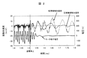
- FIG. 2 is a diagram showing a result of measuring a relationship between a compressor vibration acceleration and a piping vibration acceleration in the compressor shown in FIG. 1.
- FIG. 3 is a diagram illustrating pipe vibration suppression control by sudden deceleration in the compressor according to the first embodiment of the present invention.
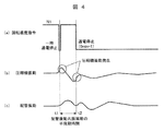
- FIG. 4 is a diagram illustrating pipe vibration suppression control by temporarily stopping power supply in the compressor according to the first embodiment of the present invention.
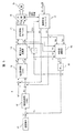
- FIG. 2 is a block diagram illustrating a configuration of a motor control device in the compressor according to the first embodiment of the present invention.
- FIG. 7 is a diagram illustrating a simulation result of vibration acceleration of a compressor and piping when a motor is normally stopped in a process of increasing a load torque in a motor control device.
- FIG. 9 is a diagram showing a result of simulating vibration acceleration of a compressor and piping when the motor is stopped after abrupt deceleration in a process of increasing a load torque in a motor control device.
- FIG. 9 is a diagram illustrating a simulation result of vibration acceleration of a compressor and piping when a motor is normally stopped in a process of decreasing a load torque in a motor control device.
- FIG. 7 is a diagram illustrating a simulation result of vibration acceleration of a compressor and piping when the motor is stopped after abrupt deceleration in the process of decreasing load torque in the motor control device.
- 1 is a schematic configuration diagram illustrating an air conditioner as a refrigeration air conditioner to which the present invention has been applied.
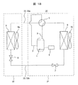
- FIG. 1A is a schematic diagram showing Embodiment 1 of the compressor of the present invention.
- the compressor 1 includes a compression mechanism 1a, a motor 1b for driving the compression mechanism 1a, and a motor control device 4 for controlling the rotation speed of the motor 1b.
- the compressor 1 is configured as a hermetic electric compressor in which the compression mechanism 1a and the motor 1b are housed in a closed container 1c.
- the compressor 1 is used for a refrigeration / air-conditioning device such as an air conditioner.
- refrigerant pipes 2 and 3 (2: suction refrigerant pipe, 3: discharge refrigerant pipe) are provided in the closed vessel 1c of the compressor 1. Is connected.
- the low-temperature and low-pressure refrigerant returned from the refrigeration cycle to the compressor 1 via the suction refrigerant pipe 2 is sucked into the compression mechanism 1a, compressed by the compression mechanism 1a, and converted into a high-temperature and high-pressure gaseous refrigerant. It is discharged from the mechanism section 1a and supplied to the refrigeration cycle via the discharged refrigerant pipe 3.
- FIG. 1B is a refrigeration cycle configuration diagram showing an example of an air conditioner as a refrigeration / air-conditioning apparatus of the present invention.
- the air conditioner 30 as a refrigerating air conditioner includes an outdoor unit 31 and an indoor unit 32.
- the outdoor unit 31 includes a hermetic electric compressor (hereinafter, also simply referred to as a compressor) 1, a four-way valve 5 for switching the circulation direction of the refrigerant from the compressor 1 via a discharge refrigerant pipe (refrigerant pipe) 3, a blower
- An outdoor heat exchanger 6 provided with 6a and an electronic expansion valve (expansion valve) 7 for heating are provided, and are sequentially connected by a refrigerant pipe.
- the suction side of the compressor 1 and the four-way valve 5 are connected by a suction refrigerant pipe 2.
- Reference numeral 4 denotes a motor control device that controls the motor 1b (see FIG. 1A) of the compressor 1.
- the indoor unit 32 is connected to the indoor heat exchanger 9 provided with the blower 9a and an electronic expansion valve (expansion valve) 8 for cooling by refrigerant piping.
- the outdoor unit 31 side and the indoor unit 32 side are connected by a refrigerant pipe 33 (33a: gas pipe, 33b: liquid pipe) to form a closed cycle refrigeration cycle.
- the compressor 1 compresses a refrigerant, which is a working medium of a refrigeration cycle, by a compression mechanism 1a.
- the high-temperature and high-pressure gaseous refrigerant discharged from the compressor 1 passes through the four-way valve 5 and is condensed by radiating heat to the outside air in the outdoor heat exchanger 6 to be condensed. It becomes a liquid refrigerant.
- the liquid refrigerant flows through the refrigerant pipe 33 (liquid pipe 33b) to the indoor unit 32 side, and is decompressed by the action of the cooling electronic expansion valve 8 to be in a low-temperature low-pressure gas-liquid two-phase state to be indoor heat exchange.
- the evaporator 9 evaporates by absorbing the heat of the indoor air.
- the refrigerant evaporated in the indoor heat exchanger 9 returns to the outdoor unit 31 through the refrigerant pipe 33 (gas pipe 33a), is drawn into the compressor 1 after passing through the four-way valve 5, and is compressed again by the compressor 1. You.
- the refrigerant flow path is switched by the four-way valve 5 from the case of the cooling operation.
- the high-temperature and high-pressure refrigerant gas discharged from the compressor 1 flows to the indoor unit 32 through the four-way valve 5 and the refrigerant pipe 33 (gas pipe 33a).
- the refrigerant that has entered the indoor unit 32 is condensed by radiating heat to the indoor air in the indoor heat exchanger 9 to become a high-pressure liquid refrigerant.
- the high-pressure liquid refrigerant flows to the outdoor unit 31 through the refrigerant pipe 33 (the liquid pipe 33b).
- the high-pressure liquid refrigerant that has entered the outdoor unit 31 is reduced in pressure by the heating electronic expansion valve 7, enters a low-temperature low-pressure gas-liquid two-phase state, flows into the outdoor heat exchanger 6, and absorbs the heat of the outdoor air. It evaporates and becomes a gaseous refrigerant.
- the refrigerant gasified in the outdoor heat exchanger 6 passes through the four-way valve 5 and is sucked into the compressor 1 and is compressed again by the compressor 1.
- the air conditioner 30 has a refrigeration cycle as described above.
- FIG. 2 is a diagram showing the results of actually measuring the relationship between the vibration acceleration of the compressor 1 and the vibration acceleration of the pipe (discharge refrigerant pipe 3) in the compressor shown in FIG.
- the motor terminal voltage (for one phase) is also shown so that the power supply to the compressor 1 is stopped.
- FIG. 3 is a diagram illustrating pipe vibration suppression control by rapid deceleration in the compressor of Embodiment 1 of the present invention.
- FIG. 4 is a diagram illustrating pipe vibration suppression control by temporarily stopping power supply in the compressor of Embodiment 1 of the present invention.
- FIGS. 3 and 4 show that before the power supply to the compressor 1 (the motor 1b) is stopped, the motor control device 4 shown in FIG. 1A generates vibrations that cancel the vibrations generated by stopping the power supply to the compressor 1.
- Pre-vibration generation control (hereinafter, also referred to as press top) is performed. This pre-vibration generation control will be described with reference to FIGS. 3 and 4, (a) is a line showing a change in the rotational speed command, (b) is a line showing a change in compressor vibration, (c) is a pipe vibration caused by the compressor vibration (the discharge refrigerant pipe has (Vibration).
- the motor control device 4 changes the rotation speed command from N1 to N2 (for example, about 100 min -1).
- the rotation speed command is reduced), and a command for rapid deceleration is issued.
- the brake torque is generated by the rapid deceleration, and accordingly, the compressor 1 vibrates as shown by the curve of “(b) compressor vibration”.
- the vibration generated in the compressor 1 also occurs in the discharge refrigerant pipe 3 connected to the compressor 1 as shown by the curve of “(c) pipe vibration” with the compressor vibration. (Hereinafter, this vibration is also referred to as “pre-vibration due to sudden deceleration”).
- the timing at which the command for the rapid deceleration is issued and the pre-vibration due to the rapid deceleration is generated is the timing at which the vibration generated by stopping the power supply to the compressor 1 (vibration due to the power stop) is generated. That is, the timing at which the pre-vibration is generated in the compressor 1 and the discharge refrigerant pipe 3 is based on the resonance frequency (resonance cycle) of the vibration of the discharge refrigerant pipe 3, as shown by the curves (b) and (c). The timing at which vibration of a phase opposite to the phase of the pipe vibration generated by stopping power supply to the machine 1 is generated.
- a pre-vibration generation control that provides rapid deceleration is performed such that pre-vibration is generated at a timing when the phase is shifted by a half cycle of the resonance cycle with respect to the phase of the pipe vibration generated by stopping power supply to the compressor 1. Just do it.
- the pre-vibration generation control is performed to generate pre-vibration in the pipe, and the resonance cycle of the pre-vibration is performed.
- the pre-vibration due to rapid deceleration and the vibration due to the stop of energization interfere to suppress the vibration of the discharge refrigerant pipe 3.
- the motor control device 4 issues a rapid deceleration command to the motor 1b, and the sudden deceleration causes the compressor 1 to vibrate, so that the refrigerant pipe connected to the compressor 1 (particularly, the discharge refrigerant pipe 3) is also provided.
- a vibration having the same phase as the vibration generated in the compressor 1 is generated to interfere with the vibration caused by stopping the power supply to the compressor 1. Thereby, the vibration of the discharge refrigerant pipe 3 can be suppressed.
- the motor control device 4 temporarily controls the compressor 1 rotating at the rotation speed command N1. This is to issue an energization stop command.
- the brake torque is also generated by temporarily stopping the energization, and the compressor 1 vibrates accordingly, as shown by the curve of “(b) compressor vibration”.
- the discharge refrigerant pipe 3 connected to the compressor 1 is also connected to the compressor 1 as shown in the curve of “(c) pipe vibration” in the same manner as described with reference to FIG. Vibration having the same phase as the generated vibration (hereinafter, this vibration is also referred to as “previbration due to temporary suspension of energization”) is generated.
- vibrations are generated in the compressor 1 and vibrations in the discharge refrigerant pipe 3 are also in the same phase as the vibrations generated in the compressor 1 (vibrations caused by stopping the power supply). Occurs.
- the timing at which the pre-vibration due to the temporary stop of the power supply is the same as the timing described with reference to FIG. That is, the timing at which the pre-vibration is generated in the compressor 1 and the discharge refrigerant pipe 3 is based on the resonance frequency (resonance cycle) of the vibration of the discharge refrigerant pipe 3, as shown by the curves (b) and (c).
- the timing at which vibration of a phase opposite to the phase of the pipe vibration generated by stopping power supply to the machine 1 is generated. More specifically, the temporary power stop command may be given at a timing when the phase is shifted by a half cycle of the resonance cycle with respect to the phase of the vibration caused by the power stop.
- a pre-vibration generation control for suddenly decelerating or temporarily stopping power supply is performed before stopping power supply to the compressor.
- a pre-vibration is intentionally generated in the discharged refrigerant pipe, and the power supply to the compressor 1 is stopped at a timing when the resonance cycle of the pipe vibration becomes the opposite phase.
- the pre-vibration by the press top and the vibration generated by stopping the energization are caused to interfere with each other, and the vibration of the pipe can be suppressed by canceling the vibration.
- the press top such as the rapid deceleration or the temporary stop of the power supply is performed once.
- the press top may be performed a plurality of times.
- the phase is shifted by a half cycle with respect to the cycle of the vibration generated by stopping the power supply to the compressor 1, and is shifted by 1.5 cycle, 2.5 cycle,. It is good to put a press top.
- the timing of applying the press top or the timing of stopping the power supply to the compressor after the press top is not limited to the timing in which the phase is shifted by a half cycle with respect to the phase of the vibration due to the stop of the power supply. Any timing can be used.
- the resonance cycle of the pipe vibration it is desirable to use a dominant value among the values obtained by measuring in advance.
- the pre-vibration generation control is performed after the compressor is decelerated to a predetermined value, so that the effect of suppressing the pipe vibration can be further improved.
- FIG. 5 is a block diagram illustrating a configuration of the motor control device 4 in the compressor of the first embodiment.
- FIG. 5 shows a position and speed estimating means for estimating the position and speed of the magnet of the motor from the detected value of the motor current flowing through the permanent magnet synchronous motor 1b, and a control device for performing vector control in the dq coordinate system based on the position and speed estimation information. ing.
- the speed command 11 outputs a motor rotation speed command ⁇ r * based on a command from the host system.
- a speed control unit (ASR: Auto Speed Regulator) 12 outputs a torque current command Iq * according to a deviation ⁇ r between the rotation speed command ⁇ r * and the rotation speed ⁇ r.
- the torque control (control for suppressing the fluctuation of the rotation speed of the motor by making the output torque of the motor 1b substantially coincide with the load torque (pulsation torque) of the compressor 1) is performed in the speed control unit 12. A detailed description of the torque control is omitted.
- An optimal current command value corresponding to the torque current Iq * is given (this is referred to as optimal current phase control).
- the current control unit (ACR: Auto Current Regulator) 13 generates a second current command value (Id ** ) so that the detected current value (Idc, Iqc) matches the given current command (Id * , Iq * ). , Iq ** ).
- the voltage command calculator 14 calculates the motor applied voltage (Vd * , Vq * ) from the second current command value (Id ** , Iq ** ) using the motor voltage equation.
- the coordinate transformations 15 and 17 are coordinate transformation means for the dq coordinate system and the three-phase AC coordinates.
- the PWM 16 performs a PWM output to the motor 1b based on the three-phase voltage commands (Vu * , Vv * , Vw * ) output from the coordinate transformation 15.
- the position / velocity estimating means includes an axis error calculating section 18, a PLL (Phase Locked Loop; phase locked loop) 19, and an integrator 20.
- the axis error calculating section 18 detects motor current values (Idc, Iqc). From the motor application voltages (Vd * , Vq * ), the rotational speed ⁇ r, and the motor constant, the error (axis error ⁇ ) between the actual phase of the motor and the control phase is calculated using the equation (1). I do.
- the PLL 19 calculates the rotation speed ⁇ r such that the axis error ⁇ becomes zero.
- the integrator 20 calculates the phase information ⁇ dc by integrating the calculated rotation speed ⁇ r.
- the motor control device 4 shown in FIG. 1 has a control configuration as shown in FIG. 5 described above.
- FIG. 6 is a diagram showing a simulation result of vibration acceleration of the compressor 1 and a pipe (discharge refrigerant pipe 3) when the motor 1b is normally stopped in the process of increasing the load torque in the motor control device 4
- FIG. FIG. 13 is a diagram illustrating a simulation result of vibration acceleration of the compressor 1 and a pipe (discharge refrigerant pipe 3) when the motor is stopped after the press-top in the process of increasing the load torque in the motor control device.
- the press top shown in FIG. 7 is for rapidly reducing the rotational speed command value (0 min ⁇ 1 in the example shown in FIG. 7), similarly to the press top described with reference to FIG.
- FIG. 8 is a diagram showing a simulation result of vibration acceleration of the compressor and the pipe when the motor is normally stopped in the process of decreasing the load torque in the motor control device.
- FIG. 9 is a diagram showing a result of simulating vibration acceleration of a compressor and piping when a motor is stopped after a press top in a process.
- the pre-vibration generation control is such that, as shown in FIG. 7, a process of decreasing the load torque (the load torque is reduced) as shown in FIG. 9 is more than a process of increasing the load torque (a period during which the load torque is increased). It can be seen that a larger pipe vibration reduction effect can be obtained by performing the process in a period during which the pressure decreases.
- FIG. 10 illustrates a configuration example when the first embodiment is applied to an air conditioner 30 that is an example of a refrigeration and air conditioning apparatus.
- FIG. 10 is a schematic configuration diagram showing an air conditioner 30 as a refrigerating air conditioner to which the present invention is applied.
- the air conditioner 30 is a room air conditioner in this embodiment, and has an outdoor unit 31 as a heat source unit having an outdoor heat exchanger as a heat source side heat exchanger, and an indoor heat exchanger as a use side heat exchanger.
- An indoor unit 32 as a use unit is provided, and the outdoor unit 31 and the indoor unit 32 are connected by a refrigerant pipe 33 (33a: gas pipe, 33b: liquid pipe) to form a refrigeration cycle as shown in FIG. 1B.
- Reference numeral 34 denotes a transmission line for performing communication between the outdoor unit 31 and the indoor unit 32
- reference numeral 35 denotes a remote controller for controlling the air conditioner 30.
- the outdoor unit 31 accommodates components such as the compressor 1, the motor control device 4, the four-way valve 5, the outdoor heat exchanger 6, and the electronic expansion valve 7 shown in FIG. 1B.
- the indoor unit 32 accommodates components such as the indoor heat exchanger 9 and the electronic expansion valve 8 shown in FIG. 1B.
- the pre-vibration generation control i.e., the motor control device 4 of the compressor 1 generates a vibration that cancels the vibration generated by stopping the power supply to the compressor 1 before the power supply to the compressor 1 is stopped). Press top).
- the compressor 1 mounted on the outdoor unit 31 is constituted by a one-cylinder rotary compressor.
- This rotary compressor is a compressor having one torque fluctuation every time the rotating shaft makes one rotation at a mechanical angle.
- the compressor 1 is a rotary compressor.
- a scroll compressor having relatively small periodic torque fluctuations and other compressors having torque fluctuations are also applicable.
- the invention is equally applicable.
- the refrigeration air conditioner the case of an air conditioner such as a room air conditioner has been described, but the present invention is not limited to the air conditioner, but includes a compressor, a heat source side heat exchanger and a use side heat exchanger,
- the present invention can be similarly applied to a refrigerating air conditioner connected to a refrigerant pipe to form a refrigerating cycle, for example, a refrigerating device such as a refrigerator.
- the embodiment of the present invention it is possible to obtain a compressor and a refrigeration / air-conditioning apparatus using the same, which can improve the effect of suppressing vibration of a compressor and piping connected to the compressor. it can. That is, after the stop button for stopping the refrigeration air conditioner is pressed and before the energization of the compressor is stopped, the pre-vibration generation control (press top) is performed to actively reduce the pipe vibration generated when the compressor is stopped. Can be suppressed. Therefore, a large vibration suppression effect can be obtained with a simple configuration, and the reliability of the compressor and the refrigeration / air-conditioning device can be improved.
Landscapes
- Engineering & Computer Science (AREA)
- Mechanical Engineering (AREA)
- General Engineering & Computer Science (AREA)
- Power Engineering (AREA)
- Physics & Mathematics (AREA)
- Thermal Sciences (AREA)
- Control Of Ac Motors In General (AREA)
- Control Of Positive-Displacement Pumps (AREA)
Abstract
圧縮機に接続されている配管の振動抑制効果を向上する。圧縮機は、圧縮機構部と、該圧縮機構部を駆動するモータと、該モータの回転速度を制御するモータ制御装置を備え、冷媒配管が接続されている。前記モータ制御装置は、圧縮機への通電停止を行う前に、圧縮機への通電停止により発生する振動を打ち消す予振動を発生させる予振動発生制御を行い、圧縮機への通電停止時に発生する振動と干渉させて、配管振動を抑制する。
Description
本発明は、圧縮機及びそれを用いた冷凍空調装置に関し、特に、永久磁石同期モータを可変速駆動するモータ駆動装置を備えるルームエアコンや冷蔵庫等の冷凍空調装置に好適なものである。
ロータリ圧縮機やレシプロ圧縮機は冷媒の圧縮過程で大きなトルク変動を生じる。このような圧縮機を適用しているエアコンや冷蔵庫などの冷凍空調装置では、低振動・低騒音化のために圧縮機の負荷トルク(脈動トルク)にモータ出力トルクを概略一致させることでモータの回転速度変動を抑制する制御(以下、トルク制御という)を用いている。トルク制御の代表例としては、特許第4221307号公報(特許文献1)に記載のものなどがある。
トルク制御を適用することにより、運転中の圧縮機やこの圧縮機に接続されている配管(例えば、吐出冷媒配管や吸入冷媒配管)の低振動化を図ることはできるが、圧縮機停止時、即ち圧縮機への通電停止に伴って発生する圧縮機の振動や圧縮機に接続されている配管の振動を低減することはできない。
そこで、圧縮機停止時に発生する圧縮機や配管(特に吐出側配管)の振動を抑制するものとして、特許第4265601号公報(特許文献2)に記載されたものなどが提案されている。この特許文献2のものでは、圧縮機を停止させる際に、ロータの速度を停止速度まで減速した後、指定するロータ位置でモータを停止させることが記載されている。
上記特許文献2に記載されているものでも、圧縮機やこれに接続されている配管の振動抑制効果はあるものの、その振動低減効果は圧縮機内の圧力や停止する回転数で変化する可能性があり、十分なものではなかった。即ち、特許文献2に記載されたものは、配管振動を受動的に抑制するものであるため、振動抑制効果を確実に得ることができるものではなかった。
本発明の目的は、圧縮機や圧縮機に接続されている配管の振動抑制効果を向上することのできる圧縮機及びそれを用いた冷凍空調装置を得ることにある。
上記目的を達成するため、本発明は、圧縮機構部と、該圧縮機構部を駆動するモータと、該モータの回転速度を制御するモータ制御装置を備え、冷媒配管が接続される圧縮機において、前記モータ制御装置は、圧縮機への通電停止を行う前に、圧縮機への通電停止により発生する振動を打ち消す予振動を発生させる予振動発生制御を行う機能を備えることを特徴とする。
本発明の他の特徴は、圧縮機、熱源側熱交換器及び利用側熱交換器を備え、冷媒配管で接続して冷凍サイクルを構成している冷凍空調装置において、前記圧縮機として上記圧縮機を用いることにある。
本発明によれば、圧縮機や圧縮機に接続されている配管の振動抑制効果を向上することのできる圧縮機及びそれを用いた冷凍空調装置を得ることができる効果がある。
以下、本発明の圧縮機及びそれを用いた冷凍空調装置の具体的実施例を図面に基づいて説明する。
本発明の実施例1を図1A、図1B、図2~図10を用いて説明する。
最初に、本発明の圧縮機の実施例1を、図1Aを用いて説明する。図1Aは本発明の圧縮機の実施例1を示す概略図である。
最初に、本発明の圧縮機の実施例1を、図1Aを用いて説明する。図1Aは本発明の圧縮機の実施例1を示す概略図である。
図1Aにおいて、圧縮機1は、圧縮機構部1aと、該圧縮機構部1aを駆動するモータ1bと、該モータ1bの回転速度を制御するモータ制御装置4を備えている。前記圧縮機1は、本実施例では、密閉容器1c内に前記圧縮機構部1aと前記モータ1bを収納している密閉型電動圧縮機として構成されている。この圧縮機1は、空気調和機などの冷凍空調装置に使用されるものであり、圧縮機1の密閉容器1cには、冷媒配管2,3(2:吸入冷媒配管、3:吐出冷媒配管)が接続されている。
冷凍サイクルから、吸入冷媒配管2を介して圧縮機1に戻された低温低圧の冷媒は圧縮機構部1aに吸入され、該圧縮機構部1aで圧縮されて高温高圧のガス状冷媒となって圧縮機構部1aから吐出され、吐出冷媒配管3を介して冷凍サイクルに供給される。
ここで、冷凍空調装置の一例としての空気調和機における冷凍サイクルの構成を、図1Bを用いて説明する。図1Bは本発明の冷凍空調装置としての空気調和機の一例を示す冷凍サイクル構成図である。
図1Bに示すように、冷凍空調装置としての空気調和機30は、室外機31と室内機32を備える。室外機31には、密閉型電動圧縮機(以下、単に圧縮機ともいう)1、この圧縮機1から吐出冷媒配管(冷媒配管)3を介して、冷媒の循環方向を切換える四方弁5、送風機6aが付設されている室外側熱交換器6、暖房用の電子膨張弁(膨張弁)7が設けられ、順次冷媒配管により接続されている。また、前記圧縮機1の吸込側と前記四方弁5は吸入冷媒配管2で接続されている。なお、4は圧縮機1のモータ1b(図1A参照)を制御するモータ制御装置である。
室内機32には、送風機9aが付設されている室内側熱交換器9と冷房用の電子膨張弁(膨張弁)8が冷媒配管で接続されている。前記室外機31側と前記室内機32側とは冷媒配管33(33a:ガス管、33b:液管)で接続されることにより、閉サイクルの冷凍サイクルを構成している。前記圧縮機1は、冷凍サイクルの作動媒体である冷媒を圧縮機構部1aで圧縮するものである。
空気調和機30を冷房運転する場合、圧縮機1から吐出された高温・高圧のガス状冷媒は、四方弁5を通って室外側熱交換器6で外気に放熱することで凝縮し、高圧の液状冷媒となる。液状冷媒は、冷媒配管33(液管33b)を通って室内機32側に流れ、冷房用の電子膨張弁8の作用で減圧されて低温低圧の気液二相状態となって室内側熱交換器9で室内空気の熱を吸収することで蒸発する。室内側熱交換器9で蒸発した冷媒は、冷媒配管33(ガス管33a)を通って室外機31へ戻り、四方弁5を通過後圧縮機1に吸入され、該圧縮機1で再び圧縮される。
次に、空気調和機が暖房運転をする場合について説明する。暖房運転の場合では、冷媒流路が四方弁5により冷房運転の場合から切り替えられる。暖房運転の場合、圧縮機1から吐出された高温・高圧の冷媒ガスは、四方弁5及び冷媒配管33(ガス管33a)を通って室内機32側に流れる。室内機32に入った冷媒は、室内側熱交換器9で室内空気に放熱することで凝縮し、高圧の液状冷媒となる。高圧の液状冷媒は、冷媒配管33(液管33b)を通って室外機31側に流れる。室外機31に入った高圧の液状冷媒は、暖房用の電子膨張弁7で減圧され、低温低圧の気液二相状態となり、室外側熱交換器6に流れて、室外空気の熱を吸収することで蒸発し、ガス状冷媒になる。室外側熱交換器6でガス状となった冷媒は、四方弁5を通過後、圧縮機1に吸入され、該圧縮機1で再び圧縮される。
空気調和機30は、以上説明したような冷凍サイクルに構成されている。
空気調和機30は、以上説明したような冷凍サイクルに構成されている。
図1Aに示す圧縮機1において、圧縮機1が振動すると、その振動が圧縮機1に接続されている吸入冷媒配管2や吐出冷媒配管3に伝達され、これらの冷媒配管を振動させる。特に、配管振動で問題となるのは、圧縮機1から吐出される冷媒を熱交換器側に送る吐出冷媒配管3である。吐出冷媒配管3は、圧縮機1の上部付近に接続されているため、圧縮機の振動が瞬時に伝達され、吐出冷媒配管3の共振周波数(固有振動数)において大きく振動するため、騒音の原因となる。
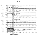
図2は図1に示す圧縮機において、圧縮機1の振動加速度と配管(吐出冷媒配管3)の振動加速度との関係を実際に測定した結果を示す線図である。なお、図2においては、圧縮機1への通電停止がわかるようにモータ端子電圧(1相分)についても合わせて表示している。
図2からわかるように、圧縮機1への通電を停止すると、圧縮機の回転エネルギーによって圧縮機1の振動が大きくなる。その後、圧縮機1の振動が吐出冷媒配管3に伝わり、その配管の共振周波数において配管振動が次第に増加していくことがわかる。なお、通電停止前は、特許文献1に示すようなトルク制御が行われているので、圧縮機や配管の振動は抑制されていることもわかる。
次に、図3、図4を用いて、本発明の実施例1の圧縮機における配管振動抑制制御について説明する。図3は本発明の実施例1の圧縮機において、急減速による配管振動抑制制御を説明する線図、図4は本発明の実施例1の圧縮機において、一時通電停止による配管振動抑制制御を説明する線図である。
図3、図4は、圧縮機1(のモータ1b)への通電停止を行う前に、図1Aに示すモータ制御装置4により、圧縮機1への通電停止により発生する振動を打ち消す振動を発生させる予振動発生制御(以下、プレストップともいう)を行うものである。この予振動発生制御について、図3、図4を用いて説明する。
図3、図4において、(a)は回転速度指令の変化を示す線、(b)は圧縮機振動の変化を示す線、(c)は圧縮機振動によって引き起こされる配管振動(吐出冷媒配管の振動)の変化を示す線である。
図3、図4において、(a)は回転速度指令の変化を示す線、(b)は圧縮機振動の変化を示す線、(c)は圧縮機振動によって引き起こされる配管振動(吐出冷媒配管の振動)の変化を示す線である。
まず、図3に示す予振動発生制御について説明する。この図3に示す例では、「(a)回転速度指令」の線に示すように、時間t1において、前記モータ制御装置4により、回転速度指令をN1からN2に変更(例えば、100min-1程度回転速度指令を低下)し急減速させる指令を出すものである。この急減速によりブレーキトルクが発生し、これに伴って、「(b)圧縮機振動」の曲線に示すように、圧縮機1が振動する。圧縮機1が振動すると、この圧縮機振動に伴い、圧縮機1に接続されている吐出冷媒配管3にも、「(c)配管振動」の曲線に示すように、圧縮機1に発生する振動と同じ位相の振動(以下、この振動を「急減速による予振動」ともいう)が発生する。
その後、時間t2において、圧縮機1への通電を停止すると、この圧縮機1への通電停止によっても、圧縮機1に振動が発生し、この振動に伴い吐出冷媒配管3にも圧縮機1に発生する振動と同じ位相の振動(以下、この振動を「通電停止による振動」ともいう)が発生する。
前記急減速の指令を出して急減速による予振動を発生させるタイミングは、圧縮機1への通電停止により発生する振動(通電停止による振動)を打ち消す振動を発生させるタイミングとする。即ち、圧縮機1及び吐出冷媒配管3に予振動を発生させるタイミングは、(b)(c)の曲線に示すように、吐出冷媒配管3の振動の共振周波数(共振周期)に基づいて、圧縮機1への通電停止により発生する配管振動の位相に対し、逆位相の振動が発生するタイミングとする。更に詳しくは、圧縮機1への通電停止により発生する配管振動の位相に対し、共振周期の半周期分、位相がずれるタイミングで予振動が発生するように、急減速を与える予振動発生制御を行えば良い。
或いは、冷凍空調装置を停止させる停止ボタンが押された後、圧縮機1への通電停止を行う前に、前記予振動発生制御を行って配管に予振動を発生させ、この予振動の共振周期の逆位相になるタイミングで圧縮機1への通電停止を行うことで、前記予振動の位相と逆位相となる振動を前記配管に発生させるようにしても良い。
このような予振動発生制御を行うことにより、(b)(c)の曲線に示すように、急減速による予振動と通電停止による振動とが干渉し、吐出冷媒配管3の振動を抑制することができる。即ち、前記モータ制御装置4からモータ1bに対し、急減速指令を出し、この急減速により圧縮機1を振動させ、圧縮機1に接続されている冷媒配管(特に、吐出冷媒配管3)にも圧縮機1に発生する振動と同じ位相の振動を発生させて、圧縮機1への通電停止による振動と干渉させる。これにより、吐出冷媒配管3の振動を抑制することができる。
次に、図4に示す予振動発生制御について説明する。この図4に示す例では、「(a)回転速度指令」の線に示すように、時間t1において、前記モータ制御装置4により、回転速度指令N1で回転している圧縮機1に対し、一時通電停止指令を出すものである。一時通電停止を行うことによってもブレーキトルクが発生し、これに伴って「(b)圧縮機振動」の曲線に示すように、圧縮機1が振動する。圧縮機1が振動すると、図3で説明したものと同様に、圧縮機1に接続されている吐出冷媒配管3にも、「(c)配管振動」の曲線に示すように、圧縮機1に発生する振動と同じ位相の振動(以下、この振動を「一時通電停止による予振動」ともいう)が発生する。
その後、時間t2において、圧縮機1への通電を停止すると、圧縮機1に振動が発生すると共に、吐出冷媒配管3にも圧縮機1に発生する振動と同じ位相の振動(通電停止による振動)が発生する。
前記一時通電停止による予振動を発生させるタイミングも、図3で説明したものと同様に、通電停止による振動を打ち消す振動を発生させるタイミングとする。即ち、圧縮機1及び吐出冷媒配管3に予振動を発生させるタイミングは、(b)(c)の曲線に示すように、吐出冷媒配管3の振動の共振周波数(共振周期)に基づいて、圧縮機1への通電停止により発生する配管振動の位相に対し、逆位相の振動が発生するタイミングとする。更に詳しくは、通電停止による振動の位相に対し、共振周期の半周期分、位相がずれるタイミングで前記一時通電停止指令を与えるようにすれば良い。
この図4に示すような予振動発生制御を行うことによっても、(b)(c)の曲線に示すように、一時通電停止による予振動と通電停止による振動とが干渉し、吐出冷媒配管3の振動を抑制することができる。
この図4に示すような予振動発生制御を行うことによっても、(b)(c)の曲線に示すように、一時通電停止による予振動と通電停止による振動とが干渉し、吐出冷媒配管3の振動を抑制することができる。
図3、図4を用いて説明したように、本実施例では、圧縮機への通電停止を行う前に、急減速や一時通電停止をする予振動発生制御(プレストップ)を行い、圧縮機1を振動させることで、意図的に吐出冷媒配管に予振動を発生させ、配管振動の共振周期の逆位相になるタイミングで圧縮機1への通電を停止するように構成している。これにより、プレストップによる予振動と通電停止により発生する振動を干渉させ、打ち消すことにより配管振動を抑制することができる。
なお、図3、図4を用いて説明した例では、急減速や一時通電停止等のプレストップを1回行うもので説明したが、プレストップを複数回行うようにしても良い。この場合には、圧縮機1への通電停止により発生する振動の周期に対し、半周期分、位相がずれるタイミングの他に、1.5周期,2.5周期,…分位相がずれるタイミングでプレストップを掛けるようにすると良い。
また、プレストップを掛けるタイミング或いはプレストップ後圧縮機への通電停止を行うタイミングについても、通電停止による振動の位相に対し、半周期分、位相がずれるタイミングには限られず、配管振動を打ち消すことができるタイミングであれば良い。更に、配管振動の共振周期については、予め測定して求めた値のうち、支配的な値を使用することが望ましい。
また、プレストップを掛けるタイミング或いはプレストップ後圧縮機への通電停止を行うタイミングについても、通電停止による振動の位相に対し、半周期分、位相がずれるタイミングには限られず、配管振動を打ち消すことができるタイミングであれば良い。更に、配管振動の共振周期については、予め測定して求めた値のうち、支配的な値を使用することが望ましい。
なお、前記予振動発生制御は、圧縮機を所定値まで減速させてから実施することにより、更に配管振動の抑制効果を向上できる。
次に、本実施例におけるモータ制御の一例を、図5を用いて簡単に説明する。図5は本実施例1の圧縮機におけるモータ制御装置4の構成を示すブロック図である。
図5は、永久磁石同期モータ1bに流れるモータ電流検出値からモータの磁石位置と速度を推定する位置速度推定手段と位置速度推定情報を基に、dq座標系でベクトル制御を行う制御装置を示している。
速度指令11は、上位系からの指令に基づいてモータの回転速度指令ωr*を出力する。速度制御部(ASR:Auto Speed Regulator)12は、回転速度指令ωr*と回転速度ωrとの偏差Δωrに従ってトルク電流指令Iq*を出力する。トルク制御(圧縮機1の負荷トルク(脈動トルク)にモータ1bの出力トルクを概略一致させることにより、モータの回転速度変動を抑制する制御)はこの速度制御部12内で行われている。トルク制御についての詳細説明は省略する。
ここで、励磁電流Id*に関しては、前記モータ1bが非突極型(Ld(d軸インダクタンス)=Lq(q軸インダクタンス))の場合は0、突極型(Ld<Lq)の場合は、トルク電流Iq*に応じた最適な電流指令値が与えられる(これを最適電流位相制御と称す)。
電流制御部(ACR:Auto Current Regulator)13は、与えられた電流指令(Id*、Iq*)に電流検出値(Idc、Iqc)が一致するように、第二の電流指令値(Id**、Iq**)を出力する。
電圧指令演算部14は、第二の電流指令値(Id**、Iq**)からモータの電圧方程式を用いてモータ印可電圧(Vd*、Vq*)を算出している。
電圧指令演算部14は、第二の電流指令値(Id**、Iq**)からモータの電圧方程式を用いてモータ印可電圧(Vd*、Vq*)を算出している。
座標変換15及び17は、dq座標系と三相交流座標の座標変換手段である。PWM16は、座標変換15からの出力である三相電圧指令(Vu*、Vv*、Vw*)を基にモータ1bにPWM出力を行う。
位置速度推定手段は、軸誤差演算部18、PLL(Phase Locked Loop;位相同期回路)19、積分器20から構成されており、前記軸誤差演算部18は、モータ電流検出値(Idc、Iqc)、モータ印可電圧(Vd*、Vq*)、回転速度ωr及びモータ定数から、モータの実際の位相と制御位相との誤差(軸誤差Δθ)を(数1)の軸誤差演算式を用いて算出する。

前記PLL19は、前記軸誤差Δθが0になるように回転速度ωrを算出している。前記積分器20は、算出された回転速度ωrを積分することで位相情報θdcを算出している。
図1に示すモータ制御装置4は、本実施例では、上述した図5に示すような制御構成を有している。
図1に示すモータ制御装置4は、本実施例では、上述した図5に示すような制御構成を有している。
次に、上述したモータ制御装置4と、圧縮機/配管振動解析モデルとを連成させたシミュレーション結果を、図6~図9により説明する。圧縮機1としては、1シリンダのロータリ圧縮機を用い、駆動時(圧縮機1の通常運転時)はトルク制御が動作している。また、図6~図9において、それぞれ、(a)は負荷トルクとモータトルクの変化、(b)は回転速度指令値、回転速度演算値及び実回転速度の変化、(c)は圧縮機振動加速度と、配管振動加速度の変化、(d)はモータ端子電圧、即ち三相電圧の変化、をそれぞれ示している。更に、図6~図9の「(c)振動加速度」を示す曲線からわかる通り、図2に示す圧縮機の振動加速度と配管振動加速度との関係を実際に測定した結果の図と同様に、圧縮機の振動発生後に配管振動が増加していく傾向が一致していることがわかる。即ち、上述した圧縮機/配管振動解析モデルを用いて配管振動を解析できることがわかる。
まず、図6、図7を用いて説明する。図6は、モータ制御装置4において、負荷トルク上昇過程でモータ1bを通常停止させた場合の圧縮機1と配管(吐出冷媒配管3)の振動加速度をシミュレーションした結果を示す線図、図7は、モータ制御装置において、負荷トルク上昇過程でプレストップ後にモータを停止させた場合の圧縮機1と配管(吐出冷媒配管3)の振動加速度をシミュレーションした結果を示す線図である。図7に示すプレストップは、図3を用いて説明したものと同様に、回転速度指令値を急減速(図7に示す例では、0min-1)させるものである。
図6の「(a)トルク」、「(b)回転速度」及び「(c)振動加速度」の曲線からわかるように、負荷トルクの上昇過程でモータ1bを通常停止させた場合、圧縮機1への通電停止により発生する圧縮機振動に伴い、配管(吐出冷媒配管3)の振動加速度が次第に増加し、大きな振動が発生する。
これに対し、図7に示すように、負荷トルク上昇過程でプレストップ後にモータを停止させた場合、図7の「(c)振動加速度」の曲線に示すように、配管の振動(振動加速度)の振幅が、図6の場合と比較して約半分になっており、配管振動を大幅に抑制できていることがわかる。
次に、図8、図9を用いて説明する。図8は、モータ制御装置において、負荷トルク下降過程でモータを通常停止させた場合の圧縮機と配管の振動加速度をシミュレーションした結果を示す線図、図9は、モータ制御装置において、負荷トルク下降過程でプレストップ後にモータを停止させた場合の圧縮機と配管の振動加速度をシミュレーションした結果を示す線図である。
図8の「(a)トルク」、「(b)回転速度」及び「(c)振動加速度」の曲線からわかるように、負荷トルクの下降過程でモータ1bを通常停止させた場合、圧縮機1への通電停止により発生する圧縮機振動に伴い、配管の振動加速度が次第に増加するが、図6に示す場合よりも配管振動は小さくなっている。
また、図9に示すように、負荷トルク下降過程でプレストップ後にモータを停止させた場合、図9の「(c)振動加速度」の曲線に示すように、配管の振動(振動加速度)の振幅が、図7や図8に示す場合と比較して約半分になっており、配管振動を更に大幅に抑制でき、大きな騒音低減効果が得られることがわかる。
図7及び図9に示すように、圧縮機1への通電停止を行う前に、圧縮機1への通電停止により発生する振動を打ち消す振動を発生させる予振動発生制御(プレストップ)を行うことにより、吐出冷媒配管3等の配管が大きく振動するのを抑制できることがわかる。また、前記予振動発生制御は、図7に示すように、負荷トルクが上昇する過程(負荷トルクが増加する期間)よりも、図9に示すように、負荷トルクが下降する過程(負荷トルクが減少する期間)で行った方が、大きな配管振動低減効果が得られることがわかる。
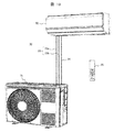
図10により、本実施例1を冷凍空調装置の一例である空気調和機30に適用した場合の構成例を説明する。図10は本発明を適用した冷凍空調装置としての空気調和機30を示す概略構成図である。
空気調和機30は、本実施例ではルームエアコンであり、熱源側熱交換器である室外熱交換器を有する熱源機としての室外機31と、利用側熱交換器である室内熱交換器を有する利用ユニットとしての室内機32を備え、前記室外機31と室内機32を冷媒配管33(33a:ガス管、33b:液管)で接続して、図1Bに示すような冷凍サイクルを構成している。なお、34は前記室外機31と前記室内機32の間で通信を行うための伝送線、35は空気調和機30を制御するためのリモコンである。
前記室外機31には、図1Bに示す圧縮機1、モータ制御装置4、四方弁5、室外側熱交換器6、電子膨張弁7等の構成部品が収容されている。また、前記室内機32には、図1Bに示す室内側熱交換器9や電子膨張弁8等の構成部品が収容されている。
前記室外機31の構成部品である前記圧縮機1に上述した本実施例の圧縮機が適用されている。具体的には、前記圧縮機1のモータ制御装置4に、圧縮機1への通電停止を行う前に、圧縮機1への通電停止により発生する振動を打ち消す振動を発生させる予振動発生制御(プレストップ)を行う機能が備えられている。
前記室外機31に搭載されている圧縮機1は、この例では、1シリンダのロータリ圧縮機で構成している。このロータリ圧縮機は、回転軸が機械角で1回転する毎に1回のトルク変動を持つ圧縮機である。
なお、図10の説明では、圧縮機1として、ロータリ圧縮機とした場合について説明したが、周期的なトルク変動が比較的少ないスクロール圧縮機や、その他のトルク変動のある圧縮機に対しても本発明は同様に適用できるものである。また、冷凍空調装置として、ルームエアコン等の空気調和機である場合について説明したが、本発明は、空気調和機に限らず、圧縮機、熱源側熱交換器及び利用側熱交換器を備え、冷媒配管で接続して冷凍サイクルを構成している冷凍空調装置、例えば冷蔵庫などの冷凍装置等にも同様に適用できるものである。
以上説明したように、本発明の実施例によれば、圧縮機や圧縮機に接続されている配管の振動抑制効果を向上することのできる圧縮機及びそれを用いた冷凍空調装置を得ることができる。即ち、冷凍空調装置を停止させる停止ボタンを押された後、圧縮機への通電停止前に、予振動発生制御(プレストップ)を行うことで、圧縮機停止時に発生する配管振動を能動的に抑制することができる。従って、簡単な構成で大きな振動抑制効果が得られ、圧縮機や冷凍空調装置の信頼性を向上することできる。
なお、本発明は上述した実施例に限定されるものではなく、様々な変形例が含まれる。また、上記した実施例は本発明を分かりやすく説明するために詳細に説明したものであり、必ずしも説明した全ての構成を備えるものに限定されるものではない。
1:圧縮機、1a:圧縮機構部、1b:モータ、1c:密閉容器、2:吸入冷媒配管、3:吐出冷媒配管、4:モータ制御装置、5:四方弁、6:室外側熱交換器、6a:送風機、7,8:電子膨張弁、9:室内側熱交換器、9a:送風機、11:速度指令、12:速度制御部、13:電流制御部、14:電圧指令演算部、15:座標変換(dq/3相)、16:PWM出力部、17:座標変換(3相/dq)、18:軸誤差演算部、19:PLL、20:積分器、30:空気調和機(ルームエアコン)、31:室外機、32:室内機、33冷媒配管(33a:ガス管、33b:液管)、34:伝送線、35:リモコン
Claims (11)
- 圧縮機構部と、該圧縮機構部を駆動するモータと、該モータの回転速度を制御するモータ制御装置を備え、冷媒配管が接続される圧縮機において、
前記モータ制御装置は、圧縮機への通電停止を行う前に、圧縮機への通電停止により発生する振動を打ち消す予振動を発生させる予振動発生制御を行う機能を備えることを特徴とする圧縮機。 - 請求項1に記載の圧縮機において、
前記モータ制御装置は、圧縮機への通電停止により発生する振動の位相と逆位相の予振動を発生させるように前記予振動発生制御を行うことを特徴とする圧縮機。 - 請求項2に記載の圧縮機において、
前記予振動発生制御による圧縮機の振動発生タイミングは、圧縮機への通電停止により発生する配管振動の位相に対し、配管振動の共振周期の半周期分、位相がずれるタイミングで予振動が発生するように、予振動発生制御を行うことを特徴とする圧縮機。 - 請求項2に記載の圧縮機において、
圧縮機への通電停止を行う前に、前記予振動発生制御を行って配管に予振動を発生させ、この予振動の共振周期の逆位相になるタイミングで圧縮機への通電停止を行うことで、前記予振動の位相と逆位相となる振動を前記配管に発生させることを特徴とする圧縮機。 - 請求項1に記載の圧縮機において、
前記圧縮機への通電停止により発生する振動を打ち消す振動を、圧縮機通電停止前に少なくとも1回発生させることを特徴とする圧縮機。 - 請求項1に記載の圧縮機において、
前記予振動発生制御は、圧縮機への通電停止を行う前に、圧縮機を急減速させるまたは圧縮機への一時的な通電停止を行うことにより、圧縮機への通電停止により発生する振動を打ち消す予振動を発生させる制御であることを特徴とする圧縮機。 - 請求項6に記載の圧縮機において、
前記予振動発生制御は、圧縮機の負荷トルクが減少する期間に実施することを特徴とする圧縮機。 - 請求項6に記載の圧縮機において、
前記予振動発生制御は、圧縮機を所定値まで減速させてから実施することを特徴とする圧縮機。 - 請求項1に記載の圧縮機において、
前記圧縮機は、密閉容器内に前記圧縮機構部と前記モータを収納している密閉型電動圧縮機であり、前記冷媒配管は前記密閉容器に接続される吐出冷媒配管と吸入冷媒配管であることを特徴とする圧縮機。 - 圧縮機、熱源側熱交換器及び利用側熱交換器を備え、冷媒配管で接続して冷凍サイクルを構成している冷凍空調装置において、
前記圧縮機として請求項1~9の何れか一項に記載の圧縮機を用いることを特徴とする冷凍空調装置。 - 請求項10に記載の冷凍空調装置において、
冷凍空調装置は空気調和機であって、圧縮機と、熱源側熱交換器である室外熱交換器を有する室外機と、利用側熱交換器である室内熱交換器を有する室内機を備え、前記室外機と室内機を冷媒配管で接続して冷凍サイクルを構成していることを特徴とする冷凍空調装置。
Priority Applications (1)
| Application Number | Priority Date | Filing Date | Title |
|---|---|---|---|
| PCT/JP2018/037396 WO2020070879A1 (ja) | 2018-10-05 | 2018-10-05 | 圧縮機及びそれを用いた冷凍空調装置 |
Applications Claiming Priority (1)
| Application Number | Priority Date | Filing Date | Title |
|---|---|---|---|
| PCT/JP2018/037396 WO2020070879A1 (ja) | 2018-10-05 | 2018-10-05 | 圧縮機及びそれを用いた冷凍空調装置 |
Publications (1)
| Publication Number | Publication Date |
|---|---|
| WO2020070879A1 true WO2020070879A1 (ja) | 2020-04-09 |
Family
ID=70055350
Family Applications (1)
| Application Number | Title | Priority Date | Filing Date |
|---|---|---|---|
| PCT/JP2018/037396 Ceased WO2020070879A1 (ja) | 2018-10-05 | 2018-10-05 | 圧縮機及びそれを用いた冷凍空調装置 |
Country Status (1)
| Country | Link |
|---|---|
| WO (1) | WO2020070879A1 (ja) |
Cited By (1)
| Publication number | Priority date | Publication date | Assignee | Title |
|---|---|---|---|---|
| JPWO2022239113A1 (ja) * | 2021-05-11 | 2022-11-17 |
Citations (7)
| Publication number | Priority date | Publication date | Assignee | Title |
|---|---|---|---|---|
| JPS48708U (ja) * | 1971-05-24 | 1973-01-08 | ||
| JPS53119403A (en) * | 1977-03-28 | 1978-10-18 | Matsushita Electric Ind Co Ltd | Motor-driven compressor |
| JPH04288460A (ja) * | 1991-03-14 | 1992-10-13 | Sharp Corp | 空気調和機 |
| JPH0580776A (ja) * | 1991-09-19 | 1993-04-02 | Toshiba Corp | 能動消音装置 |
| JP2001037281A (ja) * | 1999-05-18 | 2001-02-09 | Matsushita Electric Ind Co Ltd | 電動機のトルク制御装置 |
| WO2004083744A1 (ja) * | 2003-03-17 | 2004-09-30 | Matsushita Electric Industrial Co. Ltd. | 空気調和機 |
| JP2009024929A (ja) * | 2007-07-19 | 2009-02-05 | Mitsubishi Electric Corp | 圧縮機制御装置、冷凍空調装置およびロータリ圧縮機 |
-
2018
- 2018-10-05 WO PCT/JP2018/037396 patent/WO2020070879A1/ja not_active Ceased
Patent Citations (7)
| Publication number | Priority date | Publication date | Assignee | Title |
|---|---|---|---|---|
| JPS48708U (ja) * | 1971-05-24 | 1973-01-08 | ||
| JPS53119403A (en) * | 1977-03-28 | 1978-10-18 | Matsushita Electric Ind Co Ltd | Motor-driven compressor |
| JPH04288460A (ja) * | 1991-03-14 | 1992-10-13 | Sharp Corp | 空気調和機 |
| JPH0580776A (ja) * | 1991-09-19 | 1993-04-02 | Toshiba Corp | 能動消音装置 |
| JP2001037281A (ja) * | 1999-05-18 | 2001-02-09 | Matsushita Electric Ind Co Ltd | 電動機のトルク制御装置 |
| WO2004083744A1 (ja) * | 2003-03-17 | 2004-09-30 | Matsushita Electric Industrial Co. Ltd. | 空気調和機 |
| JP2009024929A (ja) * | 2007-07-19 | 2009-02-05 | Mitsubishi Electric Corp | 圧縮機制御装置、冷凍空調装置およびロータリ圧縮機 |
Cited By (3)
| Publication number | Priority date | Publication date | Assignee | Title |
|---|---|---|---|---|
| JPWO2022239113A1 (ja) * | 2021-05-11 | 2022-11-17 | ||
| WO2022239113A1 (ja) * | 2021-05-11 | 2022-11-17 | 三菱電機株式会社 | モータ駆動装置およびそれを有する空気調和装置の室外機 |
| JP7511753B2 (ja) | 2021-05-11 | 2024-07-05 | 三菱電機株式会社 | モータ駆動装置およびそれを有する空気調和装置の室外機 |
Similar Documents
| Publication | Publication Date | Title |
|---|---|---|
| KR100738755B1 (ko) | 모터 제어 장치, 압축기, 공기 조화기, 및 냉장고 | |
| US6977474B2 (en) | Control system for a linear vibration motor | |
| US8790089B2 (en) | Compressor speed control system for bearing reliability | |
| JP5558400B2 (ja) | 熱源システム及び熱源システムの台数制御方法 | |
| TWI663333B (zh) | 空調機及馬達控制裝置 | |
| Dianov | Estimation of the mechanical position of reciprocating compressor for silent stoppage | |
| JP6364463B2 (ja) | モータ駆動装置、及びこれを備える冷凍サイクル装置、並びにモータ駆動方法 | |
| JP4575704B2 (ja) | モータ制御装置、圧縮機、空気調和機、及び冷蔵庫 | |
| WO2018037454A1 (ja) | モータ駆動装置、ヒートポンプ装置および冷凍空調装置 | |
| WO2005029692A1 (ja) | コンプレッサの駆動装置及びそれを用いた冷蔵庫 | |
| JP2019213389A (ja) | モータ制御装置および空気調和装置 | |
| JP2012202581A (ja) | 冷凍サイクル装置及びその制御方法 | |
| JP5094256B2 (ja) | 圧縮機制御装置 | |
| US20240405694A1 (en) | Power converting apparatus, motor drive unit, and refrigeration cycle-incorporating device | |
| CN114930713B (zh) | 交流电动机的驱动装置、压缩机驱动装置以及制冷循环装置 | |
| JP7012901B2 (ja) | 交流電動機の速度推定装置、交流電動機の駆動装置、冷媒圧縮機及び冷凍サイクル装置 | |
| JP4453308B2 (ja) | 圧縮機の制御装置 | |
| WO2019116533A1 (ja) | 冷凍サイクル装置 | |
| KR101918058B1 (ko) | 브러시리스 모터의 구동 장치, 구동 방법, 및 이를 포함한 공기 조화기 | |
| JP2018148678A (ja) | モータ制御装置及び空気調和装置 | |
| KR101979453B1 (ko) | 공기 조화기 및 그의 제어방법 | |
| WO2023165620A1 (zh) | 空调器及其控制方法 | |
| JP3995377B2 (ja) | 冷凍サイクルの制御装置及びその方法 | |
| JP2024088980A (ja) | モータの駆動制御装置、モータ装置、冷凍空調機、ファン装置および駆動制御方法 | |
| TWI662782B (zh) | 馬達驅動裝置、及具備其之冷凍循環裝置、以及馬達驅動方法 |
Legal Events
| Date | Code | Title | Description |
|---|---|---|---|
| 121 | Ep: the epo has been informed by wipo that ep was designated in this application |
Ref document number: 18936017 Country of ref document: EP Kind code of ref document: A1 |
|
| NENP | Non-entry into the national phase |
Ref country code: DE |
|
| 122 | Ep: pct application non-entry in european phase |
Ref document number: 18936017 Country of ref document: EP Kind code of ref document: A1 |
|
| NENP | Non-entry into the national phase |
Ref country code: JP |