WO2020065726A1 - 光音響撮影装置 - Google Patents
光音響撮影装置 Download PDFInfo
- Publication number
- WO2020065726A1 WO2020065726A1 PCT/JP2018/035467 JP2018035467W WO2020065726A1 WO 2020065726 A1 WO2020065726 A1 WO 2020065726A1 JP 2018035467 W JP2018035467 W JP 2018035467W WO 2020065726 A1 WO2020065726 A1 WO 2020065726A1
- Authority
- WO
- WIPO (PCT)
- Prior art keywords
- acoustic wave
- sample
- propagator
- excitation light
- detection unit
- Prior art date
Links
Images


Classifications
-
- G—PHYSICS
- G01—MEASURING; TESTING
- G01N—INVESTIGATING OR ANALYSING MATERIALS BY DETERMINING THEIR CHEMICAL OR PHYSICAL PROPERTIES
- G01N29/00—Investigating or analysing materials by the use of ultrasonic, sonic or infrasonic waves; Visualisation of the interior of objects by transmitting ultrasonic or sonic waves through the object
- G01N29/04—Analysing solids
- G01N29/06—Visualisation of the interior, e.g. acoustic microscopy
- G01N29/0654—Imaging
-
- A—HUMAN NECESSITIES
- A61—MEDICAL OR VETERINARY SCIENCE; HYGIENE
- A61B—DIAGNOSIS; SURGERY; IDENTIFICATION
- A61B8/00—Diagnosis using ultrasonic, sonic or infrasonic waves
- A61B8/13—Tomography
-
- G—PHYSICS
- G01—MEASURING; TESTING
- G01N—INVESTIGATING OR ANALYSING MATERIALS BY DETERMINING THEIR CHEMICAL OR PHYSICAL PROPERTIES
- G01N29/00—Investigating or analysing materials by the use of ultrasonic, sonic or infrasonic waves; Visualisation of the interior of objects by transmitting ultrasonic or sonic waves through the object
- G01N29/22—Details, e.g. general constructional or apparatus details
- G01N29/24—Probes
- G01N29/2418—Probes using optoacoustic interaction with the material, e.g. laser radiation, photoacoustics
-
- G—PHYSICS
- G01—MEASURING; TESTING
- G01N—INVESTIGATING OR ANALYSING MATERIALS BY DETERMINING THEIR CHEMICAL OR PHYSICAL PROPERTIES
- G01N29/00—Investigating or analysing materials by the use of ultrasonic, sonic or infrasonic waves; Visualisation of the interior of objects by transmitting ultrasonic or sonic waves through the object
- G01N29/22—Details, e.g. general constructional or apparatus details
- G01N29/28—Details, e.g. general constructional or apparatus details providing acoustic coupling, e.g. water
Definitions
- the present invention relates to a photoacoustic imaging device.
- Patent Document 1 A photoacoustic imaging apparatus that irradiates a sample with pulsed excitation light and detects an acoustic wave generated in the sample to acquire an image of the sample is known (for example, see Patent Document 1).
- the apparatus disclosed in Patent Document 1 includes a water tank that fills a space between a sample and an acoustic wave detector with an acoustic wave propagation medium such as water in order to detect an acoustic wave generated in the sample without loss.
- the water tank has a form of an open container that has a bottom surface with a membrane that is in close contact with the top surface of the specimen and that opens upward.
- the acoustic wave detector is brought into close contact with the surface of the water stored inside.
- An object of the present invention is to provide a photoacoustic imaging apparatus that can reduce the size of the apparatus while securing a necessary imaging range.
- One embodiment of the present invention is an excitation light irradiator that irradiates a sample with excitation light, an acoustic wave detector that detects an acoustic wave generated at a position where the excitation light is irradiated by the excitation light irradiator, and the sample
- the acoustic wave propagator at the time of image acquisition of the sample, between the acoustic wave detection unit and the sample, disposed without interposing an air layer, and, the acoustic wave detection unit and the sample Is a photoacoustic imaging apparatus that moves with respect to the specimen in accordance with relative movement of the sample.
- an acoustic wave is generated at the irradiated position of the sample, and the acoustic wave propagates through the sample and the acoustic wave detector that is in close contact with the acoustic wave detection unit. And is detected by the acoustic wave detector.
- an acoustic wave image of the sample can be generated by measuring and arranging the magnitude of the acoustic wave at each position of the sample.
- the acoustic wave propagator moves with respect to the sample along with the relative movement between the acoustic wave detection unit and the sample.
- the membrane constituting the body is deformed according to the surface shape of the sample, and the space between the acoustic wave detection unit and the sample is filled to eliminate the intervening air layer, thereby suppressing acoustic wave loss. This makes it possible to reduce the size of the apparatus while ensuring a necessary photographing range without preparing a large water tank.
- the acoustic wave propagator may be attached to the acoustic wave detector. With this configuration, the acoustic wave propagator can be more reliably moved with respect to the sample with the relative movement between the acoustic wave detector and the sample.
- the acoustic wave detection unit includes an acoustic wave collection optical system that collects the acoustic wave, and a converter that converts the acoustic wave collected by the acoustic wave collection optical system into an electric signal.
- the acoustic wave propagator may be attached to the acoustic wave collection optical system.
- the acoustic wave detection unit may include a converter that converts the acoustic wave into an electric signal, and the acoustic wave propagator may be attached to the converter.
- the acoustic wave generated in the sample directly enters the converter via the acoustic wave propagator, and is converted into an electric signal in the converter.
- Another aspect of the present invention is an acoustic wave propagator in which an acoustic wave propagating medium is filled in a bag-like body having a film deformed following the surface shape between a sample and an acoustic wave detector. Is arranged in a state sandwiched without an air layer, and irradiates the sample with excitation light from the light source while relatively moving the light source, the acoustic wave detector and the acoustic wave propagator with respect to the sample.
- Photoacoustic imaging for detecting an acoustic wave generated at a position irradiated with the excitation light by the acoustic wave detection unit via the acoustic wave propagator, and generating an image based on the detected acoustic wave Is the way.
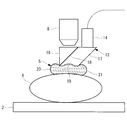
- FIG. 1 is an overall configuration diagram illustrating a photoacoustic imaging apparatus according to an embodiment of the present invention.
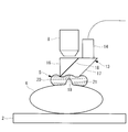
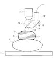
- FIG. 2 is a partially enlarged view showing a state where an acoustic wave propagator of the photoacoustic imaging apparatus of FIG. 1 is arranged above a sample.
- FIG. 3 is a partially enlarged view showing a state in which the sample is lifted from the state of FIG. 2 and the surface of the sample is brought into close contact with the acoustic wave propagator.
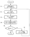
- 3 is a flowchart illustrating a photoacoustic imaging method using the photoacoustic imaging device of FIG. 1.
- FIG. 4 is a partially enlarged view showing a case where a protrusion is present on a surface of a sample in the photoacoustic imaging apparatus of FIG. 3.
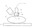
- FIG. 4 is a partially enlarged view showing a modified example of the photoacoustic imaging apparatus in FIG. 1.
- FIG. 9 is a partially enlarged view showing another modified example of the photoacoustic imaging apparatus in FIG. 1.
- a photoacoustic imaging apparatus 1 includes a stage 2 on which a sample X is mounted, and excitation for irradiating the sample X mounted on the stage 2 with laser light (excitation light).
- a light irradiating section 3 an acoustic wave detecting section 4 for detecting an acoustic wave generated in the sample X by the irradiation of the laser light, an acoustic wave propagator 5 attached to the acoustic wave detecting section 4,
- An image processing unit (image generation unit) 6 that generates an image based on the image data.
- reference numeral 7 denotes a light source that generates a pulsed laser beam.
- the stage 2 can move the mounted sample X in a three-dimensional direction. That is, the focal position of the objective lens 8 can be moved in the depth direction of the sample X by vertically moving the stage 2 with respect to the objective lens 8 described below. Further, by moving the stage 2 in the horizontal direction with respect to the objective lens 8, the irradiation position of the laser beam can be adjusted in the horizontal direction.
- the excitation light irradiation unit 3 includes an objective lens 8 that focuses the pulsed laser light generated by the light source 7 on the region of interest of the sample X.
- reference numeral 3a denotes a condenser lens
- 9 denotes a mirror
- 10 denotes a pinhole
- 11 denotes a beam splitter
- 12 denotes an eyepiece.
- the acoustic wave detection unit 4 includes a branch element (acoustic wave collection optical system) 13 that branches an acoustic wave generated in the sample X from the optical path of the laser light, and an acoustic wave transducer ( And a converter 14.
- the acoustic wave transducer 14 outputs the intensity of the detected acoustic wave as an electric signal.
- reference numeral 15 denotes an amplifier that amplifies an electric signal output from the acoustic wave transducer 14.
- the branch element 13 is configured by combining a triangular prism 16 and a parallelogram prism 17, and is arranged close to the tip of the objective lens 8.
- the inclined surface of the triangular prism 16 and the inclined surface of the parallelogram prism 17 which are arranged adjacent to each other are a liquid disposed between them, that is, a non-volatile liquid having a matching optical refractive index and a low acoustic impedance. For example, separated by a thin layer of low molecular weight silicone oil. This layer forms the branch surface 18.
- the upper surface of the triangular prism 16 that is disposed opposite to the lower end of the front end of the objective lens 8 is disposed orthogonal to the optical axis of the objective lens 8.
- the laser light emitted from the objective lens 8 and incident on the triangular prism 16 is transmitted through the branch surface 18 and emitted from the lower surface of the parallelogram prism 17 to the outside of the branch element 13.
- the refraction generated in the laser light on the upper surface and the branch surface 18 of the triangular prism 16 is suppressed, and the laser light emitted from the objective lens 8 irradiates the sample X directly vertically below.
- the lower surface of the parallelogram prism 17 emits a laser beam and receives an acoustic wave.
- a concave portion (acoustic lens) 19 for collecting an incident acoustic wave is provided on the lower surface.
- Acoustic waves entering the branching element 13 from the lower surface of the parallelogram prism 17 are collected in the concave portion 19 and enter the parallelogram prism 17, where the branch surface 18 and the branch surface 18 in the parallelogram prism 17 are formed.
- the light is emitted out of the branching element 13 from the upper surface of the parallelogram prism 17 adjacent to the opposing surface.
- the acoustic wave propagator 5 is configured by filling an acoustic wave propagating medium 21 such as water having the same refractive index as the branch element 13 and the bag 20 in the bag-like body 20 formed of a thin film.
- the bag-like body 20 is made of a material that can transmit laser light and acoustic waves, such as silicone rubber, and has a property of being deformed in accordance with the shape of a contacting object and of being closely attached to the object without any gap. Further, as the bag-like body 20, the whole is formed of a film, but the bag-shaped body 20 is not limited to this, and a part that does not contact the object may not be in the form of a film.
- the bag 20 is filled with the acoustic wave propagation medium 21 without forming an air layer inside.
- the bag-like body 20 is attached to the lower surface of the parallelogram prism 17 that is the laser light emission surface and the acoustic wave incident surface, and fills the recess 19 with an acoustic wave propagation medium 21. Since the concave portion 19 is filled with the acoustic wave propagation medium 21 having the same refractive index as the parallelogram prism 17, the concave portion 19 does not have a light condensing function for laser light and exhibits a lens function only for acoustic waves. I do.
- the image processing unit 6 generates an image based on the signal amplified by the amplifier 15 and the position information of the stage 2.
- a photoacoustic imaging method using the photoacoustic imaging device 1 according to the present embodiment configured as described above will be described with reference to the drawings.
- the sample X such as a mouse is placed on the stage 2 and the sample X is placed on the acoustic wave propagator as shown in FIG.
- the stage 2 By raising the stage 2 from the state of being placed vertically below the acoustic wave 5, the acoustic wave propagation body 5 is brought into contact with the upper surface of the sample X.
- Step S1 When the stage 2 is further raised in this state, as shown in FIGS. 3 and 4, the acoustic wave propagator 5 is deformed according to the surface shape of the sample X and is brought into close contact with the surface of the sample X without any gap.
- Step S1 When the stage 2 is raised to a position where the focal position of the objective lens 8 is located at a desired position inside the sample X, pulsed laser light is generated from the light source 7 and the laser light is condensed by the condenser lens. The light passes through the beam splitter 11 via the pinhole 3a and the pinhole 10, is condensed by the objective lens 8, passes through the branching element 13 and the acoustic wave propagator 5, and is incident on the sample X (step S2).
- the branch element 13 and the acoustic wave propagator 5 have the same refractive index, and the laser beam from the objective lens 8 is incident in a direction orthogonal to the surface of the branch element 13, so that the laser beam travels straight without being refracted, Focus within sample X.
- the acoustic wave propagator 5 Since the acoustic wave propagator 5 is in close contact with the surface of the sample X and the inside of the bag 20 of the acoustic wave propagator 5 is filled with the acoustic wave propagating medium 21, the sample X and the acoustic wave transducer 14 There is no air layer between them, and detection can be performed while reducing attenuation of acoustic waves.
- the image processing unit 6 associates the detected acoustic wave with the position information of the stage 2 (step S4). Then, it is determined whether or not the acoustic wave has been detected at all the irradiation positions (step S5). If the detection has not been completed, the stage 2 is moved by a predetermined distance in the horizontal direction, so that the laser light By changing the irradiation position in the horizontal direction (Step S6) and repeating the processes from Step S2, the image processing unit 6 can generate an image showing the acoustic wave intensity distribution.
- the stage 2 when the stage 2 is moved, the surface shape of the sample X in contact with the acoustic wave propagating body 5 changes, but the acoustic wave propagating body 5 is deformed according to the surface shape of the sample X each time. The state of close contact with the surface of the sample X is maintained. Thereby, even if the irradiation position of the laser beam is changed, the detection can be performed while reducing the attenuation of the acoustic wave.
- the shape of the acoustic wave propagator 5 is changed according to the surface shape, so that the acoustic wave can be detected stably. You can continue to do.
- the gel-like acoustic wave propagation medium 21 is applied to the surface of the sample X, it is possible to perform imaging corresponding to a certain degree of unevenness, but according to the present embodiment, the gel-like acoustic wave propagation medium 21 It is possible to easily photograph even irregularities that are too large to cope with the surface tension.
- the acoustic wave propagator 5 is attached to the acoustic wave detection unit 4 unlike the conventional method in which the objective lens 8 is moved in the water tank. Therefore, there is no need to provide a large water tank covering the relative movement range between the sample X and the objective lens 8, and there is an advantage that the apparatus can be miniaturized while securing a necessary imaging range.
- the acoustic wave propagation medium 21 is sealed inside the bag-like body 20, so that water is evaporated, dust is mixed in, and water is scattered due to the movement of the objective lens 8. There is also an advantage that occurrence of the inconvenience can be prevented beforehand.
- the branch element 13 is arranged between the objective lens 8 and the sample X, and the acoustic wave propagator 5 is attached to the branch element 13.
- the laser light may be incident on the sample X without passing through the acoustic wave propagator 5, and the acoustic wave propagator 5 may be directly attached to the acoustic wave transducer 14.
- the acoustic wave propagating body 5 in which the acoustic wave propagating medium 21 is enclosed in the bag-shaped body 20 is attached to the acoustic wave detecting unit 4, but instead, as shown in FIG. Alternatively, an independent acoustic wave propagator 5 may be interposed between the acoustic wave detector 4 and the sample X.
- the sample X is moved with respect to the acoustic wave detection unit 4 by moving the stage 2 on which the sample X is placed in a three-dimensional direction.
- the acoustic wave detector 4 may be moved in a three-dimensional direction.
- water has been exemplified as the acoustic wave propagation medium 21, any other acoustic wave propagation medium 21 may be employed.
Abstract
標本(X)に励起光を照射する励起光照射部(2)と、励起光照射部(2)により励起光が照射された位置において発生する音響波を検出する音響波検出部(4)と、標本(X)の表面形状に倣って変形する膜を有する袋状体(20)の内部に音響波伝播媒体(21)を充填してなる音響波伝播体(5)と、検出された音響波に基づいて画像を生成する画像生成部(6)とを備え、音響波伝播体(5)が、標本(X)の画像取得時に、音響波検出部(4)と標本(X)との間に、空気層を介在させずに配置され、かつ、音響波検出部(4)と標本(X)との相対移動に伴って、標本(X)に対して移動する光音響撮影装置(1)である。
Description
本発明は、光音響撮影装置に関するものである。
パルス状の励起光を標本に照射し、標本において発生した音響波を検出することにより標本の画像を取得する光音響撮影装置が知られている(例えば、特許文献1参照。)。
特許文献1の装置は、標本において発生する音響波を損失なく検出するために、標本と音響波検出器との間を水等の音響波伝播媒体で埋めるウォータタンクを備えている。ウォータタンクは、標本の上面に密着させるメンブレンを底面とし、上方に開口する開放容器の形態を有している。そして、内部に貯留された水の水面に音響波検出器を密着させている。
特許文献1の装置は、標本において発生する音響波を損失なく検出するために、標本と音響波検出器との間を水等の音響波伝播媒体で埋めるウォータタンクを備えている。ウォータタンクは、標本の上面に密着させるメンブレンを底面とし、上方に開口する開放容器の形態を有している。そして、内部に貯留された水の水面に音響波検出器を密着させている。
しかしながら、超音波検出器を標本に対して移動させる場合に、特許文献1の装置では、ウォータタンク内の水面に超音波検出器を密着させたままの状態を維持して移動させる必要がある。このため、ウォータタンクは、撮影範囲に音響波検出器の大きさを加えた大きさの開口面積を確保する必要があり、装置が大型化してしまうという不都合がある。
本発明は、必要な撮影範囲を確保しながら、装置を小型化することができる光音響撮影装置を提供することを目的としている。
本発明は、必要な撮影範囲を確保しながら、装置を小型化することができる光音響撮影装置を提供することを目的としている。
本発明の一態様は、標本に励起光を照射する励起光照射部と、該励起光照射部により前記励起光が照射された位置において発生する音響波を検出する音響波検出部と、前記標本の表面形状に倣って変形する膜を有する袋状体の内部に音響波伝播媒体を充填してなる音響波伝播体と、検出された前記音響波に基づいて画像を生成する画像生成部とを備え、前記音響波伝播体が、前記標本の画像取得時に、前記音響波検出部と前記標本との間に、空気層を介在させずに配置され、かつ、前記音響波検出部と前記標本との相対移動に伴って、前記標本に対して移動する光音響撮影装置である。
本態様によれば、パルス状の励起光が標本に照射されると、標本の照射された位置において音響波が発生し、標本および音響波検出部に密着している音響波伝播体を経由して音響波検出部により検出される。画像生成部において、標本の各位置における音響波の大きさを測定して配列することにより、標本の音響波画像を生成することができる。
この場合において、音響波伝播体は、音響波検出部と標本との相対移動に伴って標本に対して移動するので、撮影範囲よりも小さくても、必要な撮影範囲の各位置において、袋状体を構成している膜を標本の表面形状に倣って変形させ、音響波検出部と標本との間の空間を埋めて空気層の介在をなくし、音響波の損失を抑えることができる。これにより、大きなウォータタンクを用意せずに、必要な撮影範囲を確保しながら、装置を小型化することができる。
上記態様においては、前記音響波伝播体が、前記音響波検出部に取り付けられていてもよい。
この構成により、音響波検出部と標本との相対移動に伴って、音響波伝播体を標本に対して、より確実に移動させることができる。
この構成により、音響波検出部と標本との相対移動に伴って、音響波伝播体を標本に対して、より確実に移動させることができる。
また、上記態様においては、前記音響波検出部が、前記音響波を収集する音響波収集光学系と、該音響波収集光学系により収集された前記音響波を電気信号に変換する変換器とを備え、前記音響波伝播体が、前記音響波収集光学系に取り付けられていてもよい。
この構成により、標本において発生した音響波は、音響波伝播体を経由して音響波収集光学系により収集され、変換器により電気信号に変換される。
この構成により、標本において発生した音響波は、音響波伝播体を経由して音響波収集光学系により収集され、変換器により電気信号に変換される。
また、上記態様においては、前記音響波検出部が、前記音響波を電気信号に変換する変換器を備え、前記音響波伝播体が、前記変換器に取り付けられていてもよい。
この構成により、標本において発生した音響波は、音響波伝播体を経由して、直接変換器に入射し、変換器において電気信号に変換される。
この構成により、標本において発生した音響波は、音響波伝播体を経由して、直接変換器に入射し、変換器において電気信号に変換される。
また、本発明の他の態様は、標本と音響波検出部との間に、表面形状に倣って変形する膜を有する袋状体の内部に音響波伝播媒体を充填してなる音響波伝播体を、空気層を介在させずに挟んだ状態に配置し、前記標本に対して光源、前記音響波検出部および前記音響波伝播体を相対移動させながら前記光源から前記標本に励起光を照射し、前記励起光が照射された位置において発生する音響波を、前記音響波伝播体を経由して前記音響波検出部により検出し、検出された前記音響波に基づいて画像を生成する光音響撮影方法である。
本発明によれば、必要な撮影範囲を確保しながら、装置を小型化することができるという効果を奏する。
本発明の一実施形態に係る光音響撮影装置1および光音響撮影方法について図面を参照して以下に説明する。
本実施形態に係る光音響撮影装置1は、図1に示されるように、標本Xを載置するステージ2と、ステージ2に載置された標本Xにレーザ光(励起光)を照射する励起光照射部3と、レーザ光の照射により標本Xにおいて発生した音響波を検出する音響波検出部4と、音響波検出部4に取り付けられた音響波伝播体5と、検出された音響波に基づいて画像を生成する画像処理部(画像生成部)6とを備えている。図中、符号7はパルス状のレーザ光を発生する光源である。
本実施形態に係る光音響撮影装置1は、図1に示されるように、標本Xを載置するステージ2と、ステージ2に載置された標本Xにレーザ光(励起光)を照射する励起光照射部3と、レーザ光の照射により標本Xにおいて発生した音響波を検出する音響波検出部4と、音響波検出部4に取り付けられた音響波伝播体5と、検出された音響波に基づいて画像を生成する画像処理部(画像生成部)6とを備えている。図中、符号7はパルス状のレーザ光を発生する光源である。
ステージ2は、搭載した標本Xを3次元方向に移動させることができる。すなわち、後述する対物レンズ8に対してステージ2を鉛直方向に上下動させることにより、対物レンズ8の焦点位置を標本Xの深さ方向に移動させることができる。また、対物レンズ8に対してステージ2を水平方向に移動させることにより、レーザ光の照射位置を水平方向に調整することができる。
励起光照射部3は、光源7において発生したパルス状のレーザ光を標本Xの関心領域に集光する対物レンズ8を備えている。図中、符号3aは集光レンズ、9はミラー、10はピンホール、11はビームスプリッタ、12は接眼レンズである。
音響波検出部4は、標本Xにおいて発生した音響波をレーザ光の光路から分岐する分岐素子(音響波収集光学系)13と、分岐素子13の上面に接触して配置された音響波トランスデューサ(変換器)14とを備えている。音響波トランスデューサ14は、検出した音響波の強度を電気信号として出力する。図中、符号15は音響波トランスデューサ14から出力された電気信号を増幅する増幅器である。
分岐素子13は、図2に示されるように、三角プリズム16と平行四辺形プリズム17とを組み合わせて構成され、対物レンズ8の先端に近接して配置されている。
相互に隣接配置された三角プリズム16の傾斜面と平行四辺形プリズム17の傾斜面とは、両者間に配置される液体、すなわち、光学的な屈折率が整合しかつ低音響インピーダンスの不揮発性液体、例えば、低分子量シリコーンオイルの薄い層によって分離されている。この層により分岐面18が構成されている。
相互に隣接配置された三角プリズム16の傾斜面と平行四辺形プリズム17の傾斜面とは、両者間に配置される液体、すなわち、光学的な屈折率が整合しかつ低音響インピーダンスの不揮発性液体、例えば、低分子量シリコーンオイルの薄い層によって分離されている。この層により分岐面18が構成されている。
対物レンズ8の先端下方に対向して配置される三角プリズム16の上面は、対物レンズ8の光軸に直交して配置されている。
これにより、対物レンズ8から射出され、三角プリズム16に入射するレーザ光は分岐面18を透過して平行四辺形プリズム17の下面から分岐素子13外に放出される。この際に、三角プリズム16の上面および分岐面18におけるレーザ光に発生する屈折が抑えられ、対物レンズ8から射出されたレーザ光は真っ直ぐに鉛直下方の標本Xに照射される。
これにより、対物レンズ8から射出され、三角プリズム16に入射するレーザ光は分岐面18を透過して平行四辺形プリズム17の下面から分岐素子13外に放出される。この際に、三角プリズム16の上面および分岐面18におけるレーザ光に発生する屈折が抑えられ、対物レンズ8から射出されたレーザ光は真っ直ぐに鉛直下方の標本Xに照射される。
本実施形態においては、平行四辺形プリズム17の下面は、レーザ光が射出されるとともに、音響波が入射される。この下面には、入射する音響波を収集する凹部(音響レンズ)19が設けられている。平行四辺形プリズム17の下面から分岐素子13内に入射する音響波は、凹部19において収集させられて平行四辺形プリズム17内に入り、平行四辺形プリズム17内の、分岐面18および分岐面18に平行な対向面において反射された後、対向面に隣接する平行四辺形プリズム17の上面から分岐素子13外に射出される。この上面に音響波トランスデューサ14を配置しておくことにより、音響波を検出することができる。
音響波伝播体5は、薄膜からなる袋状体20の内部に、分岐素子13および袋状体20と同等の屈折率を有する水等の音響波伝播媒体21を充填することにより構成されている。袋状体20は、例えば、シリコーンゴム等のレーザ光および音響波を透過可能な材質からなり、接触する物体の形状に合わせて変形し、物体に隙間なく密着する性質を有している。また、袋状体20として、全体が膜からなるものを例示したが、これに限定されるものではなく、物体と接触しない一部が膜状ではないものを採用してもよい。
袋状体20は、内部に空気層を形成することなく、音響波伝播媒体21を充填している。袋状体20は、平行四辺形プリズム17におけるレーザ光の射出面かつ音響波の入射面である下面に取り付けられ、凹部19内を音響波伝播媒体21で埋めている。凹部19は平行四辺形プリズム17と同等の屈折率を有する音響波伝播媒体21によって埋められることにより、レーザ光に対しては集光作用を有さず、音響波に対してのみレンズ機能を発揮する。
画像処理部6は、増幅器15によって増幅された信号とステージ2の位置情報とに基づいて画像を生成する。
画像処理部6は、増幅器15によって増幅された信号とステージ2の位置情報とに基づいて画像を生成する。
このように構成された本実施形態に係る光音響撮影装置1を用いた光音響撮影方法について、図面を参照して説明する。
本実施形態に係る光音響撮影装置1を用いて標本Xの観察を行うには、ステージ2にマウス等の標本Xを載置し、図2に示されるように、標本Xを音響波伝播体5の鉛直下方に配置した状態から、ステージ2を上昇させることにより、標本Xの上面に音響波伝播体5を接触させる。
本実施形態に係る光音響撮影装置1を用いて標本Xの観察を行うには、ステージ2にマウス等の標本Xを載置し、図2に示されるように、標本Xを音響波伝播体5の鉛直下方に配置した状態から、ステージ2を上昇させることにより、標本Xの上面に音響波伝播体5を接触させる。
この状態で、ステージ2をさらに上昇させていくと、図3および図4に示されるように、音響波伝播体5が標本Xの表面形状に倣って変形し標本Xの表面に隙間なく密着させられる(ステップS1)。そして、対物レンズ8の焦点位置が標本X内部の所望の位置に配置される位置までステージ2を上昇させた時点で、光源7からパルス状のレーザ光を発生させると、レーザ光が集光レンズ3aおよびピンホール10を経てビームスプリッタ11を通過して対物レンズ8により集光され、分岐素子13および音響波伝播体5を透過して標本Xに入射される(ステップS2)。
分岐素子13および音響波伝播体5は同等の屈折率を有し、対物レンズ8からのレーザ光が分岐素子13の表面に直交する方向に入射するので、レーザ光は屈折することなく直進し、標本X内において焦点を結ぶ。
標本Xに入射したレーザ光は、対物レンズ8の焦点位置において音響波を発生させる。発生した音響波の内、音響波伝播体5側に戻った部分が、音響波伝播体5を透過して分岐素子13に入射する際に、凹部19によって収集される。そして、平行四辺形プリズム17内部の分岐面18および対向面において反射させられた後に、平行四辺形プリズム17に接触して配置されている音響波トランスデューサ14により検出される(ステップS3)。音響波伝播体5が標本Xの表面に密着しているとともに、音響波伝播体5の袋状体20の内部に音響波伝播媒体21が充満させられているので、標本Xと音響波トランスデューサ14との間に空気層が存在せず、音響波の減衰を低減しつつ検出することができる。
検出された音響波は増幅器15により増幅された後、画像処理部6において、ステージ2の位置情報と対応づけられる(ステップS4)。そして、全ての照射位置において音響波の検出が行われたか否かが判定され(ステップS5)、終了していない場合には、ステージ2を水平方向に所定距離だけ移動させることにより、レーザ光の照射位置を水平方向に変化させ(ステップS6)、ステップS2からの工程を繰り返すことにより、画像処理部6において音響波の強度分布を示す画像を生成することができる。
この場合において、ステージ2を移動させると、音響波伝播体5に接触する標本Xの表面形状が変化するが、音響波伝播体5がその都度標本Xの表面形状に倣って変形することにより、標本Xの表面との密着状態が維持される。これにより、レーザ光の照射位置を変更しても、音響波の減衰を低減しつつ検出することができる。
特に、図5に示されるように、標本Xの表面に突起等による凹凸が存在する場合においても、音響波伝播体5の形状を表面形状に倣って変化させるので、音響波を安定して検出し続けることができる。例えば、ジェル状の音響波伝播媒体21を標本Xの表面に塗布してもある程度の凹凸に対応して撮影を行うことができるが、本実施形態によれば、ジェル状の音響波伝播媒体21の表面張力では対処できない程大きな凹凸に対しても、簡易に撮影することができる。
そして、本実施形態に係る光音響撮影装置1によれば、従来のようにウォータタンク内で対物レンズ8を移動させることとは異なり、音響波伝播体5を音響波検出部4に取り付けているので、標本Xと対物レンズ8との相対移動範囲を網羅する大きなウォータタンクを設ける必要がなく、必要な撮影範囲を確保しながら、装置を小型化することができるという利点がある。
また、水面を形成するウォータタンクとは異なり、袋状体20の内部に音響波伝播媒体21を封入した状態とするので、水の蒸発、塵埃の混入および対物レンズ8の移動による水の飛散等の不都合の発生を未然に防止することができるという利点もある。
なお、本実施形態においては、対物レンズ8と標本Xとの間に分岐素子13を配置し、分岐素子13に音響波伝播体5を取り付けることにしたが、これに代えて、図6に示されるように、レーザ光については音響波伝播体5を通過させることなく標本Xに入射し、音響波トランスデューサ14に音響波伝播体5を直接取り付けることにしてもよい。
また、本実施形態においては、袋状体20に音響波伝播媒体21を封入した音響波伝播体5を音響波検出部4に取り付けることとしたが、これに代えて、図7に示されるように、音響波検出部4と標本Xとの間に、独立した音響波伝播体5を挟むことにしてもよい。
また、本実施形態においては、標本Xを載置したステージ2を3次元方向に移動させることにより、音響波検出部4に対して標本Xを移動させたが、これに代えて、ステージ2を固定し、音響波検出部4を3次元方向に移動させることにしてもよい。
音響波伝播媒体21として水を例示したが、他の任意の音響波伝播媒体21を採用してもよい。
音響波伝播媒体21として水を例示したが、他の任意の音響波伝播媒体21を採用してもよい。
1 光音響撮影装置
3 励起光照射部
4 音響波検出部
5 音響波伝播体
6 画像処理部(画像生成部)
7 光源
13 分岐素子(音響波収集光学系)
14 音響波トランスデューサ(変換器)
20 袋状体
21 音響波伝播媒体
X 標本
3 励起光照射部
4 音響波検出部
5 音響波伝播体
6 画像処理部(画像生成部)
7 光源
13 分岐素子(音響波収集光学系)
14 音響波トランスデューサ(変換器)
20 袋状体
21 音響波伝播媒体
X 標本
Claims (5)
- 標本に励起光を照射する励起光照射部と、
該励起光照射部により前記励起光が照射された位置において発生する音響波を検出する音響波検出部と、
前記標本の表面形状に倣って変形する膜を有する袋状体の内部に音響波伝播媒体を充填してなる音響波伝播体と、
検出された前記音響波に基づいて画像を生成する画像生成部とを備え、
前記音響波伝播体が、前記標本の画像取得時に、前記音響波検出部と前記標本との間に、空気層を介在させずに配置され、かつ、前記音響波検出部と前記標本との相対移動に伴って、前記標本に対して移動する光音響撮影装置。 - 前記音響波伝播体が、前記音響波検出部に取り付けられている請求項1に記載の光音響撮影装置。
- 前記音響波検出部が、前記音響波を収集する音響波収集光学系と、該音響波収集光学系により収集された前記音響波を電気信号に変換する変換器とを備え、
前記音響波伝播体が、前記音響波収集光学系に取り付けられている請求項2に記載の光音響撮影装置。 - 前記音響波検出部が、前記音響波を電気信号に変換する変換器を備え、
前記音響波伝播体が、前記変換器に取り付けられている請求項2に記載の光音響撮影装置。 - 標本と音響波検出部との間に、表面形状に倣って変形する膜を有する袋状体の内部に音響波伝播媒体を充填してなる音響波伝播体を、空気層を介在させずに挟んだ状態に配置し、
前記標本に対して光源、前記音響波検出部および前記音響波伝播体を相対移動させながら前記光源から前記標本に励起光を照射し、
前記励起光が照射された位置において発生する音響波を、前記音響波伝播体を経由して前記音響波検出部により検出し、
検出された前記音響波に基づいて画像を生成する光音響撮影方法。
Priority Applications (3)
| Application Number | Priority Date | Filing Date | Title |
|---|---|---|---|
| PCT/JP2018/035467 WO2020065726A1 (ja) | 2018-09-25 | 2018-09-25 | 光音響撮影装置 |
| JP2020547637A JPWO2020065726A1 (ja) | 2018-09-25 | 2018-09-25 | 光音響撮影装置 |
| US17/207,897 US20210208109A1 (en) | 2018-09-25 | 2021-03-22 | Photoacoustic imaging device |
Applications Claiming Priority (1)
| Application Number | Priority Date | Filing Date | Title |
|---|---|---|---|
| PCT/JP2018/035467 WO2020065726A1 (ja) | 2018-09-25 | 2018-09-25 | 光音響撮影装置 |
Related Child Applications (1)
| Application Number | Title | Priority Date | Filing Date |
|---|---|---|---|
| US17/207,897 Continuation US20210208109A1 (en) | 2018-09-25 | 2021-03-22 | Photoacoustic imaging device |
Publications (1)
| Publication Number | Publication Date |
|---|---|
| WO2020065726A1 true WO2020065726A1 (ja) | 2020-04-02 |
Family
ID=69949322
Family Applications (1)
| Application Number | Title | Priority Date | Filing Date |
|---|---|---|---|
| PCT/JP2018/035467 WO2020065726A1 (ja) | 2018-09-25 | 2018-09-25 | 光音響撮影装置 |
Country Status (3)
| Country | Link |
|---|---|
| US (1) | US20210208109A1 (ja) |
| JP (1) | JPWO2020065726A1 (ja) |
| WO (1) | WO2020065726A1 (ja) |
Citations (4)
| Publication number | Priority date | Publication date | Assignee | Title |
|---|---|---|---|---|
| JP2011519281A (ja) * | 2007-10-25 | 2011-07-07 | ワシントン・ユニバーシティ | 光学的方位分解能を備えた共焦点光音響顕微鏡検査 |
| JP2016013478A (ja) * | 2012-12-11 | 2016-01-28 | ヘルムホルツ ツェントルム ミュンヘン ドイチェス フォルシュンクスツェントルム フュア ゲスントハイト ウント ウンベルト ゲゼルシャフト ミット ベシュレンクテル ハフツング | 対象体の立体実時間光音響撮像用の手持ち式装置及び方法 |
| JP2016120184A (ja) * | 2014-12-25 | 2016-07-07 | キヤノン株式会社 | 光音響計測プローブおよび光音響計測装置 |
| US20170356884A1 (en) * | 2014-12-08 | 2017-12-14 | University Of Virginia Patent Foundation | Systems and Methods for Multispectral Photoacoustic Microscopy |
Family Cites Families (2)
| Publication number | Priority date | Publication date | Assignee | Title |
|---|---|---|---|---|
| JPH08114770A (ja) * | 1994-08-26 | 1996-05-07 | Omron Corp | 光学的ローパスフィルタおよびそれを利用したドットマトリクス表示装置 |
| US6709396B2 (en) * | 2002-07-17 | 2004-03-23 | Vermon | Ultrasound array transducer for catheter use |
-
2018
- 2018-09-25 WO PCT/JP2018/035467 patent/WO2020065726A1/ja active Application Filing
- 2018-09-25 JP JP2020547637A patent/JPWO2020065726A1/ja active Pending
-
2021
- 2021-03-22 US US17/207,897 patent/US20210208109A1/en not_active Abandoned
Patent Citations (4)
| Publication number | Priority date | Publication date | Assignee | Title |
|---|---|---|---|---|
| JP2011519281A (ja) * | 2007-10-25 | 2011-07-07 | ワシントン・ユニバーシティ | 光学的方位分解能を備えた共焦点光音響顕微鏡検査 |
| JP2016013478A (ja) * | 2012-12-11 | 2016-01-28 | ヘルムホルツ ツェントルム ミュンヘン ドイチェス フォルシュンクスツェントルム フュア ゲスントハイト ウント ウンベルト ゲゼルシャフト ミット ベシュレンクテル ハフツング | 対象体の立体実時間光音響撮像用の手持ち式装置及び方法 |
| US20170356884A1 (en) * | 2014-12-08 | 2017-12-14 | University Of Virginia Patent Foundation | Systems and Methods for Multispectral Photoacoustic Microscopy |
| JP2016120184A (ja) * | 2014-12-25 | 2016-07-07 | キヤノン株式会社 | 光音響計測プローブおよび光音響計測装置 |
Also Published As
| Publication number | Publication date |
|---|---|
| JPWO2020065726A1 (ja) | 2021-08-30 |
| US20210208109A1 (en) | 2021-07-08 |
Similar Documents
| Publication | Publication Date | Title |
|---|---|---|
| US10302569B2 (en) | Microscope device and image acquisition method | |
| US10209226B2 (en) | Photoacoustic microscope apparatus | |
| WO2013190843A1 (ja) | 光音響顕微鏡 | |
| JPS58501335A (ja) | 物体の表面および内部組織を解析する方法および装置 | |
| JP2015219502A (ja) | 光刺激装置及び光刺激方法 | |
| US20120127557A1 (en) | Apparatus and method for irradiating a medium | |
| JP2014124242A (ja) | 光音響顕微鏡 | |
| US11193886B2 (en) | Device and method for mid-infrared microscopy and analysis | |
| CN104614349A (zh) | 反射式分光瞳共焦-光声显微成像装置与方法 | |
| JP2013113804A (ja) | 光音響顕微鏡 | |
| WO2020065726A1 (ja) | 光音響撮影装置 | |
| JP5950538B2 (ja) | 被検体情報取得装置 | |
| Cikaluk et al. | Rapid ultraviolet photoacoustic remote sensing microscopy using voice-coil stage scanning | |
| JP2019012270A (ja) | 顕微鏡装置及び画像取得方法 | |
| JP2012163526A (ja) | 測定装置 | |
| JP6431928B2 (ja) | 光音響顕微鏡及び光音響信号検出方法 | |
| JP6473699B2 (ja) | 撮影装置および撮影方法 | |
| JP4518549B2 (ja) | 蛍光断層画像計測装置 | |
| KR100978600B1 (ko) | 초고분해능 주사 광학 측정 장치 | |
| KR101101988B1 (ko) | 근접 주사 광음향 측정 장치 | |
| CN104614846A (zh) | 反射式分光瞳差动共焦-光声显微成像装置与方法 | |
| JP6086719B2 (ja) | 光音響顕微鏡 | |
| JP6512801B2 (ja) | 被検体情報取得装置 | |
| US20210204817A1 (en) | Photoacoustic imaging device and method | |
| JP5313016B2 (ja) | 成分濃度分析装置及び成分濃度分析方法 |
Legal Events
| Date | Code | Title | Description |
|---|---|---|---|
| 121 | Ep: the epo has been informed by wipo that ep was designated in this application |
Ref document number: 18934854 Country of ref document: EP Kind code of ref document: A1 |
|
| ENP | Entry into the national phase |
Ref document number: 2020547637 Country of ref document: JP Kind code of ref document: A |
|
| NENP | Non-entry into the national phase |
Ref country code: DE |
|
| 122 | Ep: pct application non-entry in european phase |
Ref document number: 18934854 Country of ref document: EP Kind code of ref document: A1 |