WO2020065699A1 - 移動体位置決め制御装置及び部品実装機 - Google Patents
移動体位置決め制御装置及び部品実装機 Download PDFInfo
- Publication number
- WO2020065699A1 WO2020065699A1 PCT/JP2018/035290 JP2018035290W WO2020065699A1 WO 2020065699 A1 WO2020065699 A1 WO 2020065699A1 JP 2018035290 W JP2018035290 W JP 2018035290W WO 2020065699 A1 WO2020065699 A1 WO 2020065699A1
- Authority
- WO
- WIPO (PCT)
- Prior art keywords
- vibration
- signal
- component
- moving
- mobile object
- Prior art date
- Legal status (The legal status is an assumption and is not a legal conclusion. Google has not performed a legal analysis and makes no representation as to the accuracy of the status listed.)
- Ceased
Links
Images




Classifications
-
- G—PHYSICS
- G05—CONTROLLING; REGULATING
- G05D—SYSTEMS FOR CONTROLLING OR REGULATING NON-ELECTRIC VARIABLES
- G05D3/00—Control of position or direction
- G05D3/12—Control of position or direction using feedback
Definitions
- This specification discloses a technique relating to a moving body positioning control device including a feedback compensator that performs feedback control so that the position of a moving body such as a mounting head matches a position command and a component mounting machine.
- This type of moving object positioning control device detects the position of a moving object with a position detecting unit such as an encoder, and inputs a deviation between the detected value and a position command to a feedback compensator to reduce the deviation.
- the motor serving as the driving source is feedback-controlled by PID control or the like.
- a moving object positioning control device used in an environment where disturbance (vibration from the outside) is input to a control target as described in Patent Document 1 (Japanese Patent Application Laid-Open No. 2000-330624), Is provided with a disturbance observer for compensating the disturbance inputted to the control unit, and the disturbance is compensated by correcting the control signal (operation amount) output from the feedback compensator to the control target by the disturbance observer.
- the disturbance observer models the control target in detail and then estimates the disturbance input to the control target, and thus has the following disadvantages.
- the disturbance observer includes a delay element such as a low-pass filter in the disturbance estimation, there is a response delay in the disturbance estimation, and there is a limit in improving the positioning control performance.
- a moving object moving device that moves a moving object is set as a control target, and a detection signal of a position detecting unit that detects a position of the moving object is fed back to match the position of the moving object with a position command.
- a moving object positioning control device including a feedback compensator that controls the moving object moving device, a signal component of a predetermined frequency band corresponding to a vibration frequency band of a disturbance among the detection signals of the position detection unit.
- a band-pass filter that allows the signal to pass therethrough, and a multiplier that multiplies the signal component of the predetermined frequency band that has passed through the band-pass filter by a predetermined gain to convert the signal component into a vibration compensation signal. It is configured to correct and feed back the vibration compensation signal.
- a deviation between the position command and the detection signal of the position detection unit may be corrected by the vibration compensation signal and input to the feedback compensator.
- a band-pass filter that passes a signal component of a predetermined frequency band corresponding to a vibration frequency band of a disturbance among the detection signals of the position detection unit, and a band-pass filter of the predetermined frequency band that has passed through the band-pass filter. Since the disturbance (vibration) is compensated using a multiplier that multiplies the signal component by a predetermined gain to convert the signal component into a vibration compensation signal, a simple disturbance observer having a complicated structure as in the related art can be used. The configuration can compensate for disturbance. Moreover, since the bandpass filter has no delay with respect to the center frequency, unlike a conventional disturbance observer having a delay element such as a low-pass filter, there is no response delay in disturbance estimation, and improvement in positioning control performance can be expected.
- FIG. 1 is a perspective view schematically showing the configuration of the entire component mounter in the first embodiment.
- FIG. 2 is a block diagram showing a configuration of a control system of the component mounter.
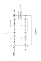
- FIG. 3 is a block diagram illustrating the configuration of the feedback control system with disturbance compensation according to the first embodiment.
- FIG. 4 is a flowchart showing the flow of processing of a filter coefficient / compensation gain identification program for identifying a filter coefficient and a compensation gain of a bandpass filter.
- FIG. 5 is a time chart showing a comparison between the waveform of the residual vibration of the positioning control with disturbance compensation and the waveform of the residual vibration of the positioning control without disturbance compensation according to the first embodiment.
- FIG. 6 is a block diagram illustrating a configuration of a feedback control system with disturbance compensation according to the second embodiment.
- a component supply device 12 for supplying components is detachably set in the component mounter 11.
- the component supply device 12 to be set in the component mounter 11 may be any of a tray feeder, a tape feeder, a bulk feeder, a stick feeder, and the like, and of course, a plurality of types of feeders may be mixed.
- the component mounter 11 includes a conveyor 13 for transporting a circuit board (not shown), a mounting head 14 (moving body) for picking up components supplied by the component supply device 12 and mounting the components on the circuit board.
- a mounting head moving device 15 (moving body moving device) that moves the head 14 in the X direction (the direction of transporting the circuit board) and the Y direction that is a direction perpendicular to the X direction, and a suction nozzle (not shown) for replacement are placed.
- a nozzle station 16 and the like are provided.
- the mounting head 14 is a rotary mounting head that holds a plurality of suction nozzles for suctioning components supplied by the component supply device 12 on an outer peripheral portion of a cylindrical rotary body. is there.
- the mounting head 14 has an R-axis motor 20 (FIG. 2) that rotates the cylindrical rotary body around an R-axis (vertical axis) at the center thereof to rotate the plurality of suction nozzles around the R-axis. ), A Q-axis motor 21 (see FIG. 2) for rotating (spinning) each suction nozzle to correct the angle of each suction nozzle (the angle of the sucked component), and lowering / moving the suction nozzle swiveled to a predetermined position.
- An ascending Z-axis motor 22 (see FIG. 2) is provided. At the time of the component suction operation or the component mounting operation, the Z-axis slide 24 (see FIG. 1) is moved down / up by the Z-axis motor 22 to move down / up the suction nozzle.
- the component mounter 11 is provided with a component imaging camera 17 that images components adsorbed by the suction nozzles of the mounting head 14 from below. Further, the mounting head 14 is provided with a mark imaging camera 18 for imaging a reference position mark or the like of the circuit board.
- the mounting head moving device 15 includes an X-axis slide device 26 using an X-axis motor 25 as a drive source, and a Y-axis slide device 28 using a Y-axis linear motor 27 as a drive source.
- the X-axis slide device 26 rotates the X-axis ball screw 29 by the X-axis motor 25 to move the X-axis slide (not shown) to which the mounting head 14 is attached in the X direction along the X-axis guide 30. .
- the X-axis guide 30 is supported by a Y-axis guide 31 of a Y-axis slide device 28 so as to be slidable in the Y direction, and has an X-axis guide 32 attached to a Y-axis slide 32 attached to a mover 33 of the Y-axis linear motor 27. 30 are connected. Thereby, the X-axis slide device 26 is moved in the Y direction along the Y-axis guide 31 by the Y-axis linear motor 27.
- the stator 34 of the Y-axis linear motor 27 is provided with two rows of magnets facing each other across the mover 33 so as to extend parallel to the Y direction.
- the X-axis slide device 26 and the Y-axis slide device 28 include, as means for detecting the position (X, Y coordinates) of the mounting head 14 in the X and Y directions, an X and Y direction position detector 45 such as an encoder or a linear scale. , 46 (see FIG. 2).
- the control device 41 of the component mounter 11 mainly includes one or a plurality of computers (CPUs), and includes an input device 42 such as a keyboard, a mouse, and a touch panel, a display device 43 such as an LCD, an EL, and a CRT.
- CPUs central processing unit
- a hard disk device that stores various data such as various control programs and control parameters for controlling the operation of each function of the component mounter 11, a nonvolatile memory device such as a flash memory and an EEPROM, and the like are connected.
- the control device 41 (moving object positioning control device) of the component mounter 11 controls the operations of the X-axis motor 25 and the Y-axis linear motor 27 of the mounting head moving device 15 during operation (during production) of the component mounter 11. Then, the mounting head 14 is moved between the component pick-up position on the component supply device 12 side, the component pick-up position above the component pick-up camera 17 and the component mounting position on the circuit board, and the component pick-up operation and the component pick-up Execute the operation and the component mounting operation.
- the X-axis motor 25 and the Y-axis linear motor 27 of the mounting head moving device 15 are composed of, for example, servo motors, and the positions of the mounting head 14 are detected by the X and Y direction position detectors 45 and 46.
- the X-axis motor 25 and the Y-axis linear motor 27 are feedback-controlled to move the mounting head 14 to the command position.
- the disturbance input to the mounting head moving device 15 to be controlled includes not only the vibration of the component mounter 11 itself but also the vibration of a structure such as a floor of a building. . If the disturbance observer attempts to compensate for such a disturbance, the structure of the disturbance observer becomes complicated, and the processing load of the control device 41 of the component mounter 11 increases. Moreover, since the disturbance observer includes a delay element such as a low-pass filter in the disturbance estimation, there is a response delay in the disturbance estimation, and there is a limit in improving the positioning control performance.
- the control device 41 of the component mounter 11 performs feedback control of the mounting head moving device 15 so that the position of the mounting head 14 matches the position command
- the control system 51 compensates for the disturbance including the vibration of the component mounter 11 and the vibration of the structure such as the floor of the building where the component mounter 11 is installed, and feedback-controls the mounting head moving device 15.
- the mounting head moving device 15 includes the X-axis slide device 26 and the Y-axis slide device 28, when the position of the mounting head 14 in the X direction is feedback-controlled, the X- The detection signal of the X-direction position detector 45 for detecting the position in the direction is fed back.
- the Y direction for detecting the position of the mounting head 14 in the Y direction is The detection signal of the position detector 46 is fed back. Therefore, the feedback control system 51 with disturbance compensation includes the feedback control system 51 with disturbance compensation in the X direction and the feedback control system 51 with disturbance compensation in the Y direction.
- Each feedback control system 51 includes a band-pass filter 52 that passes a signal component in a predetermined frequency band corresponding to a vibration frequency band of the disturbance among the detection signals of the position detection unit 45 or 46, in order to compensate for the disturbance.
- the pass frequency band (the predetermined frequency band) of the bandpass filter 52 is set to include the resonance frequency of the component mounter 11 and a structure such as a floor of a building where the component mounter 11 is installed.
- the center frequency of the band-pass filter 52 is set so as to substantially match the resonance frequency.
- the compensation gain K is a coefficient for matching the amplitude of the vibration component of the signal extracted by the band-pass filter 52 with the vibration component of the detection signal of the position detection unit 45 or 46 that feeds back.
- Each feedback control system 51 adds the detection signal of the position detection unit 45 or 46 that is fed back and the vibration compensation signal converted by the multiplier 53 by the adder 54, thereby detecting the position detection unit 45 or 46.
- the signal is corrected by the vibration compensation signal, the deviation between the position command and the corrected detection signal is calculated by the comparator 55 and input to the feedback compensator 56.
- the feedback compensator 56 calculates a control signal (operation amount) by PID control, PI control, or the like so as to reduce (close to 0) the deviation between the position command and the corrected detection signal, and to control the mounting head moving device 15. (X-axis slide device 26 or Y-axis slide device 28).
- each feedback control system 51 adjusts the X-axis slide device 26 or the X-axis slide device 26 of the mounting head moving device 15 so that the position of the mounting head 14 detected by the position detection unit 45 or 46 matches the position command while compensating for disturbance.
- the Y-axis slide device 28 is feedback-controlled.
- the functions of the feedback control system 51 as the band-pass filter 52, the multiplier 53, the adder 54, the comparator 55, and the feedback compensator 56 are performed by a feedback control program (not shown) executed by the control device 41 of the component mounter 11. ).
- the control device 41 of the component mounter 11 stores the component mounter 11 in the storage device 44 when the component mounter 11 is installed on a structure such as a floor of a building and the component mounter 11 is to be tested.
- the transfer function coefficient (filter coefficient) of the band-pass filter 52 and the compensation gain K of the multiplier 53 are identified, and these are stored in the storage device 44.
- the bandpass filter 52 and the multiplier 53 of the feedback control system 51 are automatically created at the installation site of the component mounter 11, and the feedback control system 51 can be used.
- step 101 the detection signals of the position detection units 45 and 46 are read at a predetermined sampling cycle, and the waveform of the vibration of the detection signals is read by the mounting head 14. [Function as a vibration measuring unit] Thereafter, the process proceeds to step 102, where the vibration waveform of the measured detection signal is analyzed by FFT (Fast Fourier Transform) or the like to identify the vibration frequency of the mounting head 14 [function as a vibration frequency identification unit].
- FFT Fast Fourier Transform
- step 103 the damping coefficient representing the vibration damping characteristic of the mounting head 14 identified in step 102 is identified by a half width method or the like [function as a damping coefficient identification unit].
- step 104 the coefficient (filter coefficient) of the transfer function of the band-pass filter 52 is identified using the vibration frequency and the damping coefficient of the mounting head 14 identified in steps 102 and 103, and the band-pass filter 52 [Function as bandpass filter creation unit].
- step 105 in which the signal component of the predetermined frequency band passing through the band-pass filter 52 is compared with the residual vibration measured in step 101, and the residual vibration is reduced based on the comparison result.
- the compensation gain K is identified by the least squares method or the like [function as a gain identification unit], and the program ends.
- the present inventor evaluated the case with disturbance compensation by the feedback control system 51 with disturbance compensation according to the first embodiment and the case without disturbance compensation.
- the waveform of the residual vibration of the mounting head 14 (the vibration of the deviation between the position of the mounting head 14 and the commanded position) when the mounting head 14 is positioned at the commanded position by the feedback control was measured. It is shown in FIG. From the measurement data shown in FIG. 5, the use of the feedback control system 51 with disturbance compensation according to the first embodiment sufficiently suppresses the residual vibration of the mounting head 14 as compared with the case without disturbance compensation. Has been confirmed to be accurately positioned at the command position.
- the band-pass filter 52 that passes the signal component of the predetermined frequency band corresponding to the vibration frequency band of the disturbance among the detection signals of the position detection units 45 and 46, and the band-pass filter 52 Is configured to compensate for disturbance (vibration) using a multiplier 53 that multiplies the signal component of the predetermined frequency band that has passed through by the compensation gain K and converts the signal into a vibration compensation signal.
- the disturbance can be compensated with a simple configuration without using the disturbance observer described above, and the processing load of the control device 41 of the component mounter 11 can be reduced.
- the band-pass filter 52 has no delay with respect to the center frequency, unlike a conventional disturbance observer having a delay element such as a low-pass filter, there is no response delay in disturbance estimation, and improvement in positioning control performance can be expected.
- the control device 41 of the component mounter 11 has a function of executing the filter coefficient / compensation gain identification program shown in FIG. 4, the component mounter 11 is installed on a structure such as a floor of a building to mount the component.
- the filter coefficient of the bandpass filter 52 and the compensation gain K of the multiplier 53 are automatically determined at the installation site of the component mounting machine 11.
- the bandpass filter 52 and the multiplier 53 suitable for the installation site of the component mounter 11 can be created.
- the disturbance is compensated by correcting the feedback signal (the detection signal of the position detection units 45 and 46) with the vibration compensation signal generated by the band-pass filter 52 and the multiplier 53.
- the deviation between the position command and the feedback signal (the detection signal of the position detectors 45 and 46) is corrected by the vibration compensation signal generated by the band-pass filter 52 and the multiplier 53, and the feedback compensator 56 is used. Is configured to be input. Therefore, in the second embodiment, the adder 54 of the first embodiment is eliminated, and instead, a band-pass filter 52 and a multiplier 53 are provided between the feedback compensator 56 and the mounting head moving device 15 to be controlled. An adder 57 is provided for adding the vibration compensation signal generated in step (1) to the deviation between the position command and the feedback signal (the detection signal of the position detectors 45 and 46).
- the control target is not limited to the mounting head moving device 15, and includes, for example, an R-axis driving mechanism that controls the rotation position (rotation angle) of the mounting head 14, a Q-axis driving mechanism that controls the angle of each suction nozzle, and the like.
- Another moving object moving device of the component mounter 11 may be a control target.
- the present invention is not limited to the component mounter 11, and a moving object moving device in various production apparatuses equipped with a moving object positioning control device may be controlled.
- the control device 41 of the component mounter 11 may omit the function of executing the filter coefficient / compensation gain identification program of FIG.
- the work equivalent to the work performed in each of steps 101 to 105 of the filter coefficient / compensation gain identification program in FIG. 4 is performed by an operator using an appropriate measuring instrument at the installation site of the component mounter 11. May be.
- 11 Component mounting machine
- 14 Mounting head (moving body)
- 15 Mounting head moving device (moving body moving device)
- 25 X-axis motor
- 26 X-axis sliding device (moving body moving device)
- 27 Y Axis linear motor
- 28 Y-axis slide device (moving body moving device)
- 41 control device (moving body positioning control device)
- 45 X-direction position detection unit
- 46 Y-direction position detection unit
- 51 with disturbance compensation
- 52 bandpass filter
- 53 multiplier
- 54 adder
- 55 comparator
- 56 feedback compensator
- 57 adder
Landscapes
- Physics & Mathematics (AREA)
- General Physics & Mathematics (AREA)
- Engineering & Computer Science (AREA)
- Automation & Control Theory (AREA)
- Control Of Position Or Direction (AREA)
- Supply And Installment Of Electrical Components (AREA)
Abstract
実装ヘッド等の移動体を移動させる移動体移動装置を制御対象とし、前記移動体の位置を検出する位置検出部(45,46)の検出信号をフィードバックして前記移動体の位置を位置指令に一致させるように前記移動体移動装置を制御するフィードバック補償器(56)を備える。更に、位置検出部の検出信号のうちの外乱の振動周波数帯域に相当する所定の周波数帯域の信号成分を通過させるバンドパスフィルタ(52)と、前記バンドパスフィルタを通過した所定の周波数帯域の信号成分に所定のゲインを乗算して振動補償信号に変換する乗算器(53)とを備え、前記位置検出部の検出信号を前記振動補償信号で補正してフィードバックするように構成する。
Description
本明細書は、実装ヘッド等の移動体の位置を位置指令に一致させるようにフィードバック制御するフィードバック補償器を備えた移動体位置決め制御装置及び部品実装機に関する技術を開示したものである。
この種の移動体位置決め制御装置は、移動体の位置をエンコーダ等の位置検出部で検出して、その検出値と位置指令との偏差をフィードバック補償器に入力し、当該偏差を小さくするように駆動源となるモータをPID制御等によりフィードバック制御するようにしている。更に、制御対象に外乱(外部から振動)が入力される環境下で使用する移動体位置決め制御装置においては、特許文献1(特開2000-330642号公報)に記載されているように、制御対象に入力される外乱を補償するための外乱オブザーバを設け、フィードバック補償器から制御対象に出力される制御信号(操作量)を外乱オブザーバによって補正することで外乱を補償するようにしたものがある。
一般に、外乱オブザーバは、制御対象を詳細にモデル化した上で、その制御対象に入力される外乱を推定するため、以下のような欠点があった。
(1)制御対象の詳細なモデル化によって外乱オブザーバの構造が複雑になり、演算処理負荷が増大する。特に、移動体移動装置が搭載された機械を設置した建物の床面等の構造物の強度が十分でない場合には、機械の稼働時に機械の振動によって建物の床面等の構造物も振動して機械を揺らすため、外乱オブザーバの構造が益々複雑になる。
(2)制御対象を詳細にモデル化することが困難な場合もある。
(3)外乱オブザーバは、外乱推定にローパスフィルタ等の遅れ要素を含むため、外乱推定に応答遅れがあり、位置決め制御性能の向上に限界がある。
上記課題を解決するために、移動体を移動させる移動体移動装置を制御対象とし、前記移動体の位置を検出する位置検出部の検出信号をフィードバックして前記移動体の位置を位置指令に一致させるように前記移動体移動装置を制御するフィードバック補償器を備えた移動体位置決め制御装置において、前記位置検出部の検出信号のうちの外乱の振動周波数帯域に相当する所定の周波数帯域の信号成分を通過させるバンドパスフィルタと、前記バンドパスフィルタを通過した前記所定の周波数帯域の信号成分に所定のゲインを乗算して振動補償信号に変換する乗算器とを備え、前記位置検出部の検出信号を前記振動補償信号で補正してフィードバックするように構成したものである。或は、前記位置指令と前記前記位置検出部の検出信号との偏差を前記振動補償信号で補正して前記フィードバック補償器に入力するように構成しても良い。
いずれの構成でも、位置検出部の検出信号のうちの外乱の振動周波数帯域に相当する所定の周波数帯域の信号成分を通過させるバンドパスフィルタと、このバンドパスフィルタを通過した前記所定の周波数帯域の信号成分に所定のゲインを乗算して振動補償信号に変換する乗算器を用いて外乱(振動)を補償する構成であるため、従来のような複雑な構造の外乱オブザーバを用いることなく、簡単な構成で外乱を補償することができる。しかも、バンドパスフィルタは中心周波数に対して遅れがないため、ローパスフィルタ等の遅れ要素を持つ従来の外乱オブザーバとは異なり、外乱推定に応答遅れがなく、位置決め制御性能の向上も期待できる。
以下、本明細書に開示する2つの実施例1,2を説明する。
部品実装機11に適用した実施例1を図1乃至図5に基づいて説明する。
まず、図1に基づいて部品実装機11の構成を説明する。
まず、図1に基づいて部品実装機11の構成を説明する。
部品実装機11には、部品を供給する部品供給装置12が着脱可能にセットされる。部品実装機11にセットする部品供給装置12は、トレイフィーダ、テープフィーダ、バルクフィーダ、スティックフィーダ等のいずれであっても良く、勿論、複数種類のフィーダを混載するようにしても良い。部品実装機11には、回路基板(図示せず)を搬送するコンベア13と、部品供給装置12によって供給される部品をピックアップして回路基板に実装する実装ヘッド14(移動体)と、この実装ヘッド14をX方向(回路基板の搬送方向)とその直角方向であるY方向に移動させる実装ヘッド移動装置15(移動体移動装置)と、交換用の吸着ノズル(図示せず)を載置するノズルステーション16等が設けられている。
図示はしないが、本実施例1の実装ヘッド14は、部品供給装置12によって供給される部品を吸着する複数本の吸着ノズルを円筒型の回転体の外周部に保持した回転型の実装ヘッドである。この実装ヘッド14には、前記円筒型の回転体をその中心のR軸(鉛直軸)の周りを回転させて前記複数本の吸着ノズルをR軸の周りを旋回させるR軸モータ20(図2参照)と、各吸着ノズルを回転(自転)させて各吸着ノズルの角度(吸着した部品の角度)を修正するQ軸モータ21(図2参照)と、所定位置に旋回した吸着ノズルを下降/上昇させるZ軸モータ22(図2参照)が設けられている。部品吸着動作時や部品実装動作時には、Z軸モータ22によってZ軸スライド24(図1参照)を下降/上昇させることで、吸着ノズルを下降/上昇させるようになっている。
部品実装機11には、実装ヘッド14の各吸着ノズルに吸着した部品を下方から撮像する部品撮像用のカメラ17が設けられている。また、実装ヘッド14には、回路基板の基準位置マーク等を撮像するマーク撮像用のカメラ18が設けられている。
実装ヘッド移動装置15は、X軸モータ25を駆動源とするX軸スライド装置26と、Y軸リニアモータ27を駆動源とするY軸スライド装置28とから構成されている。X軸スライド装置26は、X軸モータ25でX軸ボールねじ29を回転させて、実装ヘッド14が取り付けられたX軸スライド(図示せず)をX軸ガイド30に沿ってX方向に移動させる。X軸ガイド30は、Y軸スライド装置28のY軸ガイド31にY方向にスライド可能に支持され、且つ、Y軸リニアモータ27の可動子33に取り付けられたY軸スライド32に、X軸ガイド30が連結されている。これにより、Y軸リニアモータ27によってX軸スライド装置26がY軸ガイド31に沿ってY方向に移動されるようになっている。Y軸リニアモータ27の固定子34には、可動子33を挟んで対向する2列の磁石の列がY方向に平行に延びるように設けられている。
X軸スライド装置26とY軸スライド装置28には、実装ヘッド14のX,Y方向の位置(X,Y座標)を検出する手段として、エンコーダやリニアスケール等のX,Y方向位置検出部45,46(図2参照)が設けられている。
部品実装機11の制御装置41は、1台又は複数台のコンピュータ(CPU)を主体として構成され、キーボード、マウス、タッチパネル等の入力装置42と、LCD、EL、CRT等の表示装置43と、部品実装機11の各機能の動作を制御する各種制御プログラムや制御パラメータ等の各種データを記憶保持するハードディスク装置、フラッシュメモリ、EEPROM等の不揮発性の記憶装置44等が接続されている。
部品実装機11の制御装置41(移動体位置決め制御装置)は、部品実装機11の稼働中(生産中)に、実装ヘッド移動装置15のX軸モータ25とY軸リニアモータ27の動作を制御して、実装ヘッド14を部品供給装置12側の部品吸着位置と部品撮像用のカメラ17の上方の部品撮像位置と回路基板上の部品実装位置との間を移動させて部品吸着動作と部品撮像動作と部品実装動作を実行する。本実施例1では、実装ヘッド移動装置15のX軸モータ25とY軸リニアモータ27は、例えばサーボモータにより構成され、実装ヘッド14の位置をX,Y方向位置検出部45,46で検出しながら実装ヘッド14を指令位置まで移動させるようにX軸モータ25とY軸リニアモータ27がフィードバック制御される。
この場合、部品実装機11を設置した建物の床面等の構造物の強度が十分でない場合には、部品実装機11の稼働時に部品実装機11の振動によって建物の床面等の構造物も振動して部品実装機11を揺らすため、制御対象である実装ヘッド移動装置15に入力される外乱は、部品実装機11自身の振動に加え、建物の床面等の構造物の振動も含まれる。このような外乱を外乱オブザーバで補償しようとすると、外乱オブザーバの構造が複雑になり、部品実装機11の制御装置41の演算処理負荷が増大する。しかも、外乱オブザーバは、外乱推定にローパスフィルタ等の遅れ要素を含むため、外乱推定に応答遅れがあり、位置決め制御性能の向上に限界がある。
そこで、本実施例1では、部品実装機11の制御装置41が実装ヘッド14の位置を位置指令に一致させるように実装ヘッド移動装置15をフィードバック制御する際に、図3に示す外乱補償付きフィードバック制御系51を用いて部品実装機11の振動とそれが設置された建物の床面等の構造物の振動を含む外乱を補償して実装ヘッド移動装置15をフィードバック制御する。
この場合、実装ヘッド移動装置15は、X軸スライド装置26とY軸スライド装置28とから構成されているため、実装ヘッド14のX方向の位置をフィードバック制御する場合には、実装ヘッド14のX方向の位置を検出するX方向位置検出部45の検出信号をフィードバックし、一方、実装ヘッド14のY方向の位置をフィードバック制御する場合には、実装ヘッド14のY方向の位置を検出するY方向位置検出部46の検出信号をフィードバックする。従って、外乱補償付きフィードバック制御系51は、X方向の外乱補償付きフィードバック制御系51とY方向の外乱補償付きフィードバック制御系51とが設けられている。
各フィードバック制御系51は、外乱を補償するために、位置検出部45又は46の検出信号のうちの外乱の振動周波数帯域に相当する所定の周波数帯域の信号成分を通過させるバンドパスフィルタ52と、このバンドパスフィルタ52を通過した前記所定の周波数帯域の信号成分に所定の補償ゲインKを乗算して振動補償信号に変換する乗算器53とを備える。ここで、バンドパスフィルタ52の通過周波数帯域(前記所定の周波数帯域)は、部品実装機11とそれが設置された建物の床面等の構造物との共振周波数を含むように設定されている。好ましくは、バンドパスフィルタ52の中心周波数が上記共振周波数とほぼ一致するように設定すると良い。また、補償ゲインKは、バンドパスフィルタ52で抽出した信号の振動成分とフィードバックする位置検出部45又は46の検出信号の振動成分の振幅を合わせるための係数である。
各フィードバック制御系51は、フィードバックされる位置検出部45又は46の検出信号と、乗算器53で変換された振動補償信号とを加算器54で加算することで、位置検出部45又は46の検出信号を振動補償信号で補正し、位置指令と補正後の検出信号との偏差を比較器55で演算してフィードバック補償器56に入力する。このフィードバック補償器56は、位置指令と補正後の検出信号との偏差を小さくする(0に近付ける)ようにPID制御又はPI制御等により制御信号(操作量)を演算して実装ヘッド移動装置15(X軸スライド装置26又はY軸スライド装置28)に出力する。これにより、各フィードバック制御系51は、外乱を補償しながら、位置検出部45又は46で検出した実装ヘッド14の位置を位置指令に一致させるように実装ヘッド移動装置15のX軸スライド装置26又はY軸スライド装置28をフィードバック制御する。
各フィードバック制御系51のバンドパスフィルタ52、乗算器53、加算器54、比較器55及びフィードバック補償器56としての機能は、部品実装機11の制御装置41が実行するフィードバック制御プログラム(図示せず)によって実現される。
更に、本実施例1では、部品実装機11の制御装置41は、部品実装機11を建物の床面等の構造物に設置して部品実装機11を試運転するときに、記憶装置44に記憶された図4のフィルタ係数/補償ゲイン同定プログラムを実行することで、バンドパスフィルタ52の伝達関数の係数(フィルタ係数)及び乗算器53の補償ゲインKを同定して、それらを記憶装置44に記憶する。これにより、部品実装機11の設置現場でフィードバック制御系51のバンドパスフィルタ52と乗算器53が自動的に作成されてフィードバック制御系51が使用可能な状態となる。
次に、部品実装機11の制御装置41が実行する図4のフィルタ特性/補償ゲイン同定プログラムの処理内容を説明する。部品実装機11の制御装置41は、本プログラムを起動すると、まず、ステップ101で、位置検出部45,46の検出信号を所定のサンプリング周期で読み込んでその検出信号の振動の波形を実装ヘッド14の振動の波形として測定する[振動測定部としての機能]。この後、ステップ102に進み、測定した検出信号の振動の波形をFFT(高速フーリエ変換)等で解析して実装ヘッド14の振動周波数を同定する[振動周波数同定部としての機能]。
この後、ステップ103に進み、上記ステップ102で同定した実装ヘッド14の振動の減衰特性を表す減衰係数を半値幅法等で同定する[減衰系数同定部としての機能]。この後、ステップ104に進み、上記ステップ102及び103で同定された実装ヘッド14の振動周波数及び減衰係数を用いてバンドパスフィルタ52の伝達関数の係数(フィルタ係数)を同定してバンドパスフィルタ52を作成する[バンドパスフィルタ作成部としての機能]。
この後、ステップ105に進み、バンドパスフィルタ52を通過した所定の周波数帯域の信号成分と前記ステップ101で測定した残留振動とを比較して、その比較結果に基づいて残留振動が小さくなるように補償ゲインKを最小二乗法等で同定して[ゲイン同定部としての機能]、本プログラムを終了する。
本発明者は、本実施例1の外乱補償付きフィードバック制御系51による外乱補償効果を確認するために、本実施例1の外乱補償付きフィードバック制御系51による外乱補償ありの場合と、外乱補償なしの場合について、フィードバック制御により実装ヘッド14を指令位置に位置決めしたときの実装ヘッド14の残留振動(実装ヘッド14の位置と指令位置との偏差の振動)の波形を測定したので、その測定結果を図5に示している。この図5の測定データから、本実施例1の外乱補償付きフィードバック制御系51を使用すれば、外乱補償がない場合と比較して、実装ヘッド14の残留振動が十分に抑えられて実装ヘッド14が指令位置に精度良く位置決めされることが確認された。
以上説明した本実施例1では、位置検出部45,46の検出信号のうちの外乱の振動周波数帯域に相当する所定の周波数帯域の信号成分を通過させるバンドパスフィルタ52と、このバンドパスフィルタ52を通過した前記所定の周波数帯域の信号成分に補償ゲインKを乗算して振動補償信号に変換する乗算器53を用いて外乱(振動)を補償する構成であるため、従来のような複雑な構造の外乱オブザーバを用いることなく、簡単な構成で外乱を補償することができ、部品実装機11の制御装置41の演算処理負荷を軽減できる。しかも、バンドパスフィルタ52は中心周波数に対して遅れがないため、ローパスフィルタ等の遅れ要素を持つ従来の外乱オブザーバとは異なり、外乱推定に応答遅れがなく、位置決め制御性能の向上も期待できる。
しかも、部品実装機11の制御装置41は、図4のフィルタ係数/補償ゲイン同定プログラムを実行する機能を備えているため、部品実装機11を建物の床面等の構造物に設置して部品実装機11を試運転するときに、図4のフィルタ係数/補償ゲイン同定プログラムを実行することで、部品実装機11の設置現場でバンドパスフィルタ52のフィルタ係数と乗算器53の補償ゲインKを自動的に同定することができ、部品実装機11の設置現場に対応した適切なバンドパスフィルタ52と乗算器53を作成できる利点もある。
次に、図6を用いて実施例2を説明する。但し、前記実施例1と実質的に同一の部分については同一符号を付して説明を省略又は簡略化し、主として異なる部分について説明する。
前記実施例1では、バンドパスフィルタ52及び乗算器53で生成した振動補償信号でフィードバック信号(位置検出部45,46の検出信号)を補正することで外乱を補償するようにしたが、図6に示す実施例2では、位置指令とフィードバック信号(位置検出部45,46の検出信号)との偏差を、バンドパスフィルタ52及び乗算器53で生成した振動補償信号で補正してフィードバック補償器56に入力するように構成している。従って、本実施例2では、前記実施例1の加算器54を廃止し、その代わりに、フィードバック補償器56と制御対象の実装ヘッド移動装置15との間に、バンドパスフィルタ52及び乗算器53で生成した振動補償信号を、位置指令とフィードバック信号(位置検出部45,46の検出信号)との偏差に加算する加算器57を設けている。
以上のように構成した本実施例2においても、前記実施例2と同様の効果を得ることができる。
[その他の実施例]
制御対象は、実装ヘッド移動装置15に限定されず、例えば、実装ヘッド14の回転位置(回転角度)を制御するR軸軸駆動機構、各吸着ノズルの角度を制御するQ軸軸駆動機構等、部品実装機11の他の移動体移動装置を制御対象としても良い。或は、部品実装機11に限定されず、移動体位置決め制御装置を搭載した様々な生産装置における移動体移動装置を制御対象としても良い。
制御対象は、実装ヘッド移動装置15に限定されず、例えば、実装ヘッド14の回転位置(回転角度)を制御するR軸軸駆動機構、各吸着ノズルの角度を制御するQ軸軸駆動機構等、部品実装機11の他の移動体移動装置を制御対象としても良い。或は、部品実装機11に限定されず、移動体位置決め制御装置を搭載した様々な生産装置における移動体移動装置を制御対象としても良い。
また、部品実装機11の制御装置41は、図4のフィルタ係数/補償ゲイン同定プログラムを実行する機能を省略しても良い。この場合、図4のフィルタ係数/補償ゲイン同定プログラムの各ステップ101~105で行う作業と同等の作業を、部品実装機11の設置現場で作業者が適宜の測定器具を使用して行うようにしても良い。
その他、本発明は、前記各実施例に限定されず、要旨を逸脱しない範囲内で種々変更して実施しても良いことは勿論である。
11…部品実装機、14…実装ヘッド(移動体)、15…実装ヘッド移動装置(移動体移動装置)、25…X軸モータ、26…X軸スライド装置(移動体移動装置)、27…Y軸リニアモータ、28…Y軸スライド装置(移動体移動装置)、41…制御装置(移動体位置決め制御装置)、45…X方向位置検出部、46…Y方向位置検出部、51…外乱補償付きフィードバック制御系、52…バンドパスフィルタ、53…乗算器、54…加算器、55…比較器、56…フィードバック補償器、57…加算器
Claims (8)
- 移動体を移動させる移動体移動装置を制御対象とし、前記移動体の位置を検出する位置検出部の検出信号をフィードバックして前記移動体の位置を位置指令に一致させるように前記移動体移動装置を制御するフィードバック補償器を備えた移動体位置決め制御装置において、
前記位置検出部の検出信号のうちの外乱の振動周波数帯域に相当する所定の周波数帯域の信号成分を通過させるバンドパスフィルタと、
前記バンドパスフィルタを通過した前記所定の周波数帯域の信号成分に所定のゲインを乗算して振動補償信号に変換する乗算器とを備え、
前記位置検出部の検出信号を前記振動補償信号で補正してフィードバックするように構成されている、移動体位置決め制御装置。 - 移動体を移動させる移動体移動装置を制御対象とし、前記移動体の位置を検出する位置検出部の検出信号をフィードバックして前記移動体の位置を位置指令に一致させるように前記移動体移動装置を制御するフィードバック補償器を備えた移動体位置決め制御装置において、
前記位置検出部の検出信号のうちの外乱の振動周波数帯域に相当する所定の周波数帯域の信号成分を通過させるバンドパスフィルタと、
前記バンドパスフィルタを通過した前記所定の周波数帯域の信号成分に所定のゲインを乗算して振動補償信号に変換する乗算器とを備え、
前記位置指令と前記前記位置検出部の検出信号との偏差を前記振動補償信号で補正して前記フィードバック補償器に入力するように構成されている、移動体位置決め制御装置。 - 前記所定の周波数帯域は、前記移動体移動装置が搭載された機械とその機械が設置された構造物との共振周波数を含むように設定されている、請求項1又は2に記載の移動体位置決め制御装置。
- 前記位置検出部の検出信号を所定のサンプリング周期で読み込んで前記移動体の振動の波形を測定する振動測定部と、
前記振動測定部で測定した前記移動体の振動の波形を解析してその振動周波数を同定する振動周波数同定部と、
前記移動体の振動の減衰特性を表す減衰系数を同定する減衰系数同定部と、
前記振動周波数同定部及び前記減衰系数同定部で同定された前記振動周波数及び前記減衰系数を用いて前記バンドパスフィルタの伝達関数の係数を同定して前記バンドパスフィルタを作成するバンドパスフィルタ作成部と
を備える、請求項3に記載の移動体位置決め制御装置。 - 前記バンドパスフィルタを通過した前記所定の周波数帯域の信号成分と前記振動測定部で測定した残留振動とを比較してその比較結果に基づいて前記残留振動が小さくなるように前記所定のゲインを同定するゲイン同定部を備える、請求項4に記載の移動体位置決め制御装置。
- 前記移動体移動装置は、前記移動体を前後左右方向であるXY方向に移動させるように構成されている、請求項1乃至5のいずれかに記載の移動体位置決め制御装置。
- 請求項1乃至6のいずれかに記載の移動体位置決め制御装置が搭載されている、部品実装機。
- 前記移動体は、部品供給装置から供給される電子部品をピックアップして回路基板に実装する実装ヘッドである、請求項7に記載の部品実装機。
Priority Applications (2)
| Application Number | Priority Date | Filing Date | Title |
|---|---|---|---|
| PCT/JP2018/035290 WO2020065699A1 (ja) | 2018-09-25 | 2018-09-25 | 移動体位置決め制御装置及び部品実装機 |
| JP2020547616A JP7050171B2 (ja) | 2018-09-25 | 2018-09-25 | 移動体位置決め制御装置及び部品実装機 |
Applications Claiming Priority (1)
| Application Number | Priority Date | Filing Date | Title |
|---|---|---|---|
| PCT/JP2018/035290 WO2020065699A1 (ja) | 2018-09-25 | 2018-09-25 | 移動体位置決め制御装置及び部品実装機 |
Publications (1)
| Publication Number | Publication Date |
|---|---|
| WO2020065699A1 true WO2020065699A1 (ja) | 2020-04-02 |
Family
ID=69949764
Family Applications (1)
| Application Number | Title | Priority Date | Filing Date |
|---|---|---|---|
| PCT/JP2018/035290 Ceased WO2020065699A1 (ja) | 2018-09-25 | 2018-09-25 | 移動体位置決め制御装置及び部品実装機 |
Country Status (2)
| Country | Link |
|---|---|
| JP (1) | JP7050171B2 (ja) |
| WO (1) | WO2020065699A1 (ja) |
Citations (5)
| Publication number | Priority date | Publication date | Assignee | Title |
|---|---|---|---|---|
| JPH07224839A (ja) * | 1994-02-15 | 1995-08-22 | Seiko Seiki Co Ltd | 磁気軸受装置 |
| JPH09112482A (ja) * | 1995-10-20 | 1997-05-02 | Koyo Seiko Co Ltd | ターボ分子ポンプ |
| JP2005115586A (ja) * | 2003-10-07 | 2005-04-28 | Yaskawa Electric Corp | フィードバック制御装置およびその振動抑制方法 |
| JP2007021512A (ja) * | 2005-07-13 | 2007-02-01 | Kawasaki Plant Systems Ltd | ダウンコイラーのラッパーロール制御装置 |
| JP2017010300A (ja) * | 2015-06-23 | 2017-01-12 | 富士機械製造株式会社 | 作業装置及びその制御方法 |
-
2018
- 2018-09-25 WO PCT/JP2018/035290 patent/WO2020065699A1/ja not_active Ceased
- 2018-09-25 JP JP2020547616A patent/JP7050171B2/ja active Active
Patent Citations (5)
| Publication number | Priority date | Publication date | Assignee | Title |
|---|---|---|---|---|
| JPH07224839A (ja) * | 1994-02-15 | 1995-08-22 | Seiko Seiki Co Ltd | 磁気軸受装置 |
| JPH09112482A (ja) * | 1995-10-20 | 1997-05-02 | Koyo Seiko Co Ltd | ターボ分子ポンプ |
| JP2005115586A (ja) * | 2003-10-07 | 2005-04-28 | Yaskawa Electric Corp | フィードバック制御装置およびその振動抑制方法 |
| JP2007021512A (ja) * | 2005-07-13 | 2007-02-01 | Kawasaki Plant Systems Ltd | ダウンコイラーのラッパーロール制御装置 |
| JP2017010300A (ja) * | 2015-06-23 | 2017-01-12 | 富士機械製造株式会社 | 作業装置及びその制御方法 |
Also Published As
| Publication number | Publication date |
|---|---|
| JP7050171B2 (ja) | 2022-04-07 |
| JPWO2020065699A1 (ja) | 2021-03-11 |
Similar Documents
| Publication | Publication Date | Title |
|---|---|---|
| US6515442B1 (en) | Position controller | |
| JP6012742B2 (ja) | 作業装置 | |
| US8154226B2 (en) | Operating apparatus | |
| JP5852505B2 (ja) | 部品または基板の作業装置および部品実装装置 | |
| JP5918622B2 (ja) | 部品または基板の作業装置および部品実装装置 | |
| JPH0448698A (ja) | 電子部品取付装置 | |
| JP6630500B2 (ja) | 作業装置及びその制御方法 | |
| JP2015213139A (ja) | 位置決め装置 | |
| JP7473572B2 (ja) | 構成装置良否判定方法 | |
| JP2013062290A (ja) | 実装基板製造システムおよび実装基板の製造方法 | |
| JP7050171B2 (ja) | 移動体位置決め制御装置及び部品実装機 | |
| JP3946046B2 (ja) | 機械の制振制御方法および制振制御型機械 | |
| JP4421991B2 (ja) | 移載装置、表面実装機、誤差テーブルの作成方法、プログラムおよび記憶媒体 | |
| JP6076790B2 (ja) | 電子部品実装装置 | |
| JP2000069782A (ja) | 直線方向駆動装置 | |
| US20170305012A1 (en) | Conveyance method and conveyance device | |
| JP6510282B2 (ja) | 部品実装装置 | |
| JP7307546B2 (ja) | 基板作業装置 | |
| US11382246B2 (en) | Substrate work system under adjustable rail spacing distance | |
| JP6270841B2 (ja) | 検査制御装置、実装システム及び検査制御方法 | |
| JP7105882B2 (ja) | 制御パラメータ調整システム及び制御パラメータ調整方法 | |
| JP2019012784A (ja) | 部品保持具の偏心補正方法 | |
| EP3790368B1 (en) | Use method of work machine | |
| JP3247703B2 (ja) | プリント基板作業装置およびそれの送り装置誤差検出装置 | |
| KR20210121636A (ko) | 전자부품실장방법 |
Legal Events
| Date | Code | Title | Description |
|---|---|---|---|
| 121 | Ep: the epo has been informed by wipo that ep was designated in this application |
Ref document number: 18934851 Country of ref document: EP Kind code of ref document: A1 |
|
| ENP | Entry into the national phase |
Ref document number: 2020547616 Country of ref document: JP Kind code of ref document: A |
|
| NENP | Non-entry into the national phase |
Ref country code: DE |
|
| 122 | Ep: pct application non-entry in european phase |
Ref document number: 18934851 Country of ref document: EP Kind code of ref document: A1 |