WO2020065632A1 - 光ファイバ母材 - Google Patents
光ファイバ母材 Download PDFInfo
- Publication number
- WO2020065632A1 WO2020065632A1 PCT/IB2019/058290 IB2019058290W WO2020065632A1 WO 2020065632 A1 WO2020065632 A1 WO 2020065632A1 IB 2019058290 W IB2019058290 W IB 2019058290W WO 2020065632 A1 WO2020065632 A1 WO 2020065632A1
- Authority
- WO
- WIPO (PCT)
- Prior art keywords
- optical fiber
- refractive index
- fiber preform
- core
- ratio
- Prior art date
- Legal status (The legal status is an assumption and is not a legal conclusion. Google has not performed a legal analysis and makes no representation as to the accuracy of the status listed.)
- Ceased
Links
Images



Classifications
-
- C—CHEMISTRY; METALLURGY
- C03—GLASS; MINERAL OR SLAG WOOL
- C03B—MANUFACTURE, SHAPING, OR SUPPLEMENTARY PROCESSES
- C03B37/00—Manufacture or treatment of flakes, fibres, or filaments from softened glass, minerals, or slags
- C03B37/01—Manufacture of glass fibres or filaments
- C03B37/012—Manufacture of preforms for drawing fibres or filaments
- C03B37/014—Manufacture of preforms for drawing fibres or filaments made entirely or partially by chemical means, e.g. vapour phase deposition of bulk porous glass either by outside vapour deposition [OVD], or by outside vapour phase oxidation [OVPO] or by vapour axial deposition [VAD]
- C03B37/01413—Reactant delivery systems
- C03B37/0142—Reactant deposition burners
-
- C—CHEMISTRY; METALLURGY
- C03—GLASS; MINERAL OR SLAG WOOL
- C03B—MANUFACTURE, SHAPING, OR SUPPLEMENTARY PROCESSES
- C03B37/00—Manufacture or treatment of flakes, fibres, or filaments from softened glass, minerals, or slags
- C03B37/01—Manufacture of glass fibres or filaments
- C03B37/012—Manufacture of preforms for drawing fibres or filaments
- C03B37/014—Manufacture of preforms for drawing fibres or filaments made entirely or partially by chemical means, e.g. vapour phase deposition of bulk porous glass either by outside vapour deposition [OVD], or by outside vapour phase oxidation [OVPO] or by vapour axial deposition [VAD]
- C03B37/01406—Deposition reactors therefor
-
- C—CHEMISTRY; METALLURGY
- C03—GLASS; MINERAL OR SLAG WOOL
- C03B—MANUFACTURE, SHAPING, OR SUPPLEMENTARY PROCESSES
- C03B37/00—Manufacture or treatment of flakes, fibres, or filaments from softened glass, minerals, or slags
- C03B37/01—Manufacture of glass fibres or filaments
- C03B37/012—Manufacture of preforms for drawing fibres or filaments
- C03B37/014—Manufacture of preforms for drawing fibres or filaments made entirely or partially by chemical means, e.g. vapour phase deposition of bulk porous glass either by outside vapour deposition [OVD], or by outside vapour phase oxidation [OVPO] or by vapour axial deposition [VAD]
- C03B37/018—Manufacture of preforms for drawing fibres or filaments made entirely or partially by chemical means, e.g. vapour phase deposition of bulk porous glass either by outside vapour deposition [OVD], or by outside vapour phase oxidation [OVPO] or by vapour axial deposition [VAD] by glass deposition on a glass substrate, e.g. by inside-, modified-, plasma- or plasma modified- chemical vapour deposition [ICVD, MCVD, PCVD, PMCVD], i.e. by thin layer coating on the inside or outside of a glass tube or on a glass rod
-
- G—PHYSICS
- G01—MEASURING; TESTING
- G01B—MEASURING LENGTH, THICKNESS OR SIMILAR LINEAR DIMENSIONS; MEASURING ANGLES; MEASURING AREAS; MEASURING IRREGULARITIES OF SURFACES OR CONTOURS
- G01B11/00—Measuring arrangements characterised by the use of optical techniques
- G01B11/08—Measuring arrangements characterised by the use of optical techniques for measuring diameters
-
- G—PHYSICS
- G01—MEASURING; TESTING
- G01B—MEASURING LENGTH, THICKNESS OR SIMILAR LINEAR DIMENSIONS; MEASURING ANGLES; MEASURING AREAS; MEASURING IRREGULARITIES OF SURFACES OR CONTOURS
- G01B11/00—Measuring arrangements characterised by the use of optical techniques
- G01B11/24—Measuring arrangements characterised by the use of optical techniques for measuring contours or curvatures
- G01B11/2408—Measuring arrangements characterised by the use of optical techniques for measuring contours or curvatures for measuring roundness
-
- G—PHYSICS
- G01—MEASURING; TESTING
- G01M—TESTING STATIC OR DYNAMIC BALANCE OF MACHINES OR STRUCTURES; TESTING OF STRUCTURES OR APPARATUS, NOT OTHERWISE PROVIDED FOR
- G01M11/00—Testing of optical apparatus; Testing structures by optical methods not otherwise provided for
- G01M11/30—Testing of optical devices, constituted by fibre optics or optical waveguides
- G01M11/37—Testing of optical devices, constituted by fibre optics or optical waveguides in which light is projected perpendicularly to the axis of the fibre or waveguide for monitoring a section thereof
-
- G—PHYSICS
- G02—OPTICS
- G02B—OPTICAL ELEMENTS, SYSTEMS OR APPARATUS
- G02B6/00—Light guides; Structural details of arrangements comprising light guides and other optical elements, e.g. couplings
- G02B6/02—Optical fibres with cladding with or without a coating
-
- G—PHYSICS
- G02—OPTICS
- G02B—OPTICAL ELEMENTS, SYSTEMS OR APPARATUS
- G02B6/00—Light guides; Structural details of arrangements comprising light guides and other optical elements, e.g. couplings
- G02B6/02—Optical fibres with cladding with or without a coating
- G02B6/028—Optical fibres with cladding with or without a coating with core or cladding having graded refractive index
-
- C—CHEMISTRY; METALLURGY
- C03—GLASS; MINERAL OR SLAG WOOL
- C03B—MANUFACTURE, SHAPING, OR SUPPLEMENTARY PROCESSES
- C03B2203/00—Fibre product details, e.g. structure, shape
- C03B2203/10—Internal structure or shape details
- C03B2203/22—Radial profile of refractive index, composition or softening point
-
- C—CHEMISTRY; METALLURGY
- C03—GLASS; MINERAL OR SLAG WOOL
- C03B—MANUFACTURE, SHAPING, OR SUPPLEMENTARY PROCESSES
- C03B2207/00—Glass deposition burners
- C03B2207/04—Multi-nested ports
- C03B2207/06—Concentric circular ports
-
- C—CHEMISTRY; METALLURGY
- C03—GLASS; MINERAL OR SLAG WOOL
- C03B—MANUFACTURE, SHAPING, OR SUPPLEMENTARY PROCESSES
- C03B2207/00—Glass deposition burners
- C03B2207/20—Specific substances in specified ports, e.g. all gas flows specified
-
- C—CHEMISTRY; METALLURGY
- C03—GLASS; MINERAL OR SLAG WOOL
- C03B—MANUFACTURE, SHAPING, OR SUPPLEMENTARY PROCESSES
- C03B2207/00—Glass deposition burners
- C03B2207/50—Multiple burner arrangements
-
- C—CHEMISTRY; METALLURGY
- C03—GLASS; MINERAL OR SLAG WOOL
- C03B—MANUFACTURE, SHAPING, OR SUPPLEMENTARY PROCESSES
- C03B2207/00—Glass deposition burners
- C03B2207/70—Control measures
-
- C—CHEMISTRY; METALLURGY
- C03—GLASS; MINERAL OR SLAG WOOL
- C03B—MANUFACTURE, SHAPING, OR SUPPLEMENTARY PROCESSES
- C03B37/00—Manufacture or treatment of flakes, fibres, or filaments from softened glass, minerals, or slags
- C03B37/01—Manufacture of glass fibres or filaments
- C03B37/012—Manufacture of preforms for drawing fibres or filaments
- C03B37/014—Manufacture of preforms for drawing fibres or filaments made entirely or partially by chemical means, e.g. vapour phase deposition of bulk porous glass either by outside vapour deposition [OVD], or by outside vapour phase oxidation [OVPO] or by vapour axial deposition [VAD]
- C03B37/01446—Thermal after-treatment of preforms, e.g. dehydrating, consolidating, sintering
-
- G—PHYSICS
- G02—OPTICS
- G02B—OPTICAL ELEMENTS, SYSTEMS OR APPARATUS
- G02B6/00—Light guides; Structural details of arrangements comprising light guides and other optical elements, e.g. couplings
- G02B6/02—Optical fibres with cladding with or without a coating
- G02B6/028—Optical fibres with cladding with or without a coating with core or cladding having graded refractive index
- G02B6/0281—Graded index region forming part of the central core segment, e.g. alpha profile, triangular, trapezoidal core
-
- G—PHYSICS
- G02—OPTICS
- G02B—OPTICAL ELEMENTS, SYSTEMS OR APPARATUS
- G02B6/00—Light guides; Structural details of arrangements comprising light guides and other optical elements, e.g. couplings
- G02B6/02—Optical fibres with cladding with or without a coating
- G02B6/036—Optical fibres with cladding with or without a coating core or cladding comprising multiple layers
- G02B6/03605—Highest refractive index not on central axis
- G02B6/03611—Highest index adjacent to central axis region, e.g. annular core, coaxial ring, centreline depression affecting waveguiding
Definitions
- the present invention relates to an optical fiber preform.
- the optical fiber preform becomes an optical fiber by drawing and reducing the diameter.
- An optical fiber preform of a communication optical fiber has a core portion having a relatively high refractive index and a clad portion disposed around the core portion and having a relatively low refractive index.
- a core deposition burner for depositing a core portion and a clad deposition burner for depositing a clad portion outside the core may be installed and used at the same time.
- an important parameter that determines the optical characteristics of an optical fiber is the ratio of the diameter of the core to the diameter of the clad. This ratio greatly affects the mode field diameter of the optical fiber. For this reason, even at the stage of the optical fiber preform, it is required to more finely grasp the ratio between the diameter of the core portion and the diameter of the clad portion and the amount of change in the ratio in the longitudinal direction of the optical fiber preform.
- Patent Document 1 JP 2005-308717 A
- the method described in the above document irradiates parallel light from the side of the preform and measures the intensity distribution of transmitted light through the optical fiber preform. According to this method, the relative value of the core diameter can be obtained in a shorter time than in the preform analyzer.
- the outer diameter of the preform can be measured in a short time by using a laser outer diameter measuring device, each core measured from a plurality of circumferential angles in the same cross section of the optical fiber preform using the method of the above-mentioned document.
- the non-circularity of the core can be obtained in a short time based on the relative value of the diameter.
- the outer diameter ratio which is the ratio to the outer diameter of the core portion
- the ratio between the measured value measured by the method of the above-mentioned document and the measured value measured using the preform analyzer is constant in the longitudinal direction of the base material. It turns out that there is no case.
- the optical fiber preform may have a core having a relatively high refractive index. In one embodiment of the present invention, the optical fiber preform may have a clad portion having a relatively low refractive index. In one embodiment of the present invention, the optical fiber preform has the refractive index of the clad portion as a reference 0.0 of the refractive index ratio in a section from the core portion where the refractive index changes in the radial direction of the optical fiber preform to the clad portion.
- the absolute value of the ratio of the refractive index difference between the refractive index of the optical fiber preform at the second position where the refractive index ratio is 0.75 and the interval (mm) between the first position and the second position is When calculated according to the following Equation 1, it may be 0.0015 (/ mm) or more.
- the optical fiber preform has a refractive index distribution in which a curve indicating a change in the refractive index in the radial direction of the optical fiber preform causes an inflection point on the outer peripheral side of the first position. May be.
- the optical fiber preform may have a core equivalent diameter of the substantially cylindrical portion of 22 mm or more.
- FIG. 2 is a schematic cross-sectional view showing a structure of a burner 20. It is a figure explaining the concept of the refractive index ratio in an optical fiber preform.
- 5 is a graph showing a change in a refractive index ratio in a radial direction of an optical fiber preform. It is a figure which shows and compares the measurement result of core part equivalent diameter. It is a figure which shows and compares the measurement result of core part equivalent diameter.
- 6 is a graph comparing changes in the refractive index ratio of the optical fiber preform. It is a figure which shows and compares the measurement result of core part equivalent diameter.
- FIG. 1 is a schematic diagram for explaining a method for producing a glass fine particle deposit body 12 serving as an optical fiber preform. As shown in FIG. 1, the glass fine particle deposit body 12 was sprayed from a core portion deposition burner 13, a first cladding portion deposition burner 14, and a second cladding portion deposition burner 15 near the lower end of the starting material 11. It is manufactured by depositing glass particles.
- FIG. 1 also shows the burner position in the case of manufacturing the glass fine particle deposit body 12.
- the core part deposition burner 13 is disposed at the lowest position independently of the first clad part deposition burner 14 and the second clad part deposition burner 15.
- the core part deposition burner 13 forms a core part of the glass particulate deposit body 12 by injecting a flame accompanied by a dopant material such as germanium tetrachloride in addition to silicon tetrachloride as a glass material.
- the first cladding deposition burner 14 and the second cladding deposition burner 15 are disposed above the core deposition burner 13, and the core deposition burner 13 is configured to place the core deposited on the starting material 11 on the outside.
- the clad portion is formed so as to cover the cladding.
- the glass particle deposit body 12 is manufactured using a plurality of burners as a whole.
- the manufactured glass particle deposit 12 is dehydrated by heating in a furnace tube containing, for example, chlorine gas, and then further heated in a furnace tube in a helium gas atmosphere to form a transparent glass, thereby becoming an optical fiber preform. .
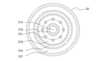
- FIG. 2 is a schematic cross-sectional view showing a structure of a burner 20 that can be used as the first clad part deposition burner 14 and the second clad part deposition burner 15.
- the illustrated burner 20 has a plurality of concentrically arranged injection ports 21a, 21b, 21d, 21e, 21f and a group of small-diameter injection ports 21c, and simultaneously injects combustible gas, oxygen gas, shield gas, and the like. .
- the burner 14 for depositing the first clad portion and the burner 15 for depositing the second clad portion also have a role other than the deposition of the clad portion.
- cracking of the glass particulate deposit body 12 is prevented by baking the core portion with a flame to increase the density.
- the diameter of the core is reduced by baking to prevent re-adhesion of the germanium oxide particulates floating without adhering to the glass particulate deposit body 12.
- the temperature of the core portion is increased by a flame to volatilize excess germanium oxide.
- Example 1 Using the equipment shown in FIG. 1 and FIG. 2, a glass fine particle deposit 12 was produced. 9.3 L / min of oxygen, 6.8 L / min of hydrogen, 0.38 L / min of argon, 0.46 L / min of silicon tetrachloride, and 17 mL / min of germanium tetrachloride were passed through the core portion deposition burner 13.
- the glass particle deposit body 12 manufactured under the above conditions was heated to about 1200 ° C. in a furnace tube containing chlorine gas to be dehydrated. After that, the glass particle deposit body 12 was heated to about 1500 ° C. in a furnace tube in a helium gas atmosphere to be vitrified transparently. Thus, an optical fiber preform was obtained.
- the refractive index distribution was measured with a preform analyzer at a cylindrical portion having a generally stable diameter except for the tapered portions at both ends in the longitudinal direction. As a result, it was found that the core had a diameter of 22.0 mm. Further, in the radial direction of the optical fiber preform, the value of the ratio R obtained at the position where the refractive index ratio is 0.25 and the position where the refractive index ratio is 0.75 is 0.00167 (1 / mm). there were.
- the refractive index ratio and the ratio R are defined as follows.
- FIG. 3 is a diagram illustrating the concept of the refractive index ratio in the optical fiber preform.
- FIG. 3 shows a radial refractive index distribution of the optical fiber preform.
- the refractive index ratio is based on the refractive index of the cladding having a relatively low refractive index as a reference 0.0, and the maximum value of the refractive index of the core having a relatively high refractive index is 1.0. It is a relative value.
- the refractive index of the clad portion was a refractive index at a position where the outer diameter ratio, which is a ratio to the outer diameter in the radial direction of the optical fiber preform, was 95%.
- FIG. 4 is a graph showing a change in the refractive index ratio in a section including the boundary between the core portion and the clad portion in the radial direction of the optical fiber preform.
- the “boundary between the core portion and the cladding portion” refers to the position where the refractive index ratio of the optical fiber preform becomes 0.75 and the refractive index ratio becomes 0.25 in the radial direction of the optical fiber preform. It means a section between the position.
- the radial position means a distance from the center of the optical fiber preform in the radial direction of the optical fiber preform.
- the ratio R in the above optical fiber preform is a value defined by the following equation 1.
- a curve indicating a change in the refractive index ratio includes an inflection point on the outer peripheral side of the boundary between the core and the clad. Therefore, in the entire optical fiber preform, the refractive index that decreases from the core to the cladding increases at the position of the inflection point.
- the inflection point of the refractive index ratio can be formed by adjusting the gas flow rate of the first cladding deposition burner 14.
- the ratio of the combustible gas or the auxiliary gas to the glass raw material such as silicon tetrachloride may be adjusted to be higher.
- the diameter of the core portion of the above optical fiber preform was measured using a parallel light beam.
- a dimension measuring device LS-9030D using a green LED parallel light manufactured by Keyence Corporation was used. Parallel light was irradiated from the side of the optical fiber preform, and the light transmitted through the optical fiber preform was received, and the light intensity distribution was measured from an image taken. The distance between the two dark portions of the measured light intensity distribution is defined as the core equivalent diameter (relative value of the core diameter) of the optical fiber preform, and is repeated at a pitch of 1 mm along the longitudinal direction of the optical fiber preform. The core equivalent diameter was measured at the position.
- the refractive index distribution was measured at intervals of 20 to 100 mm in the longitudinal direction using a preform analyzer, and the half value width of the refractive index of the core was taken as the diameter of the core.
- the half value width of the refractive index of the core was taken as the diameter of the core.
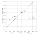
- FIG. 5 is a diagram showing a comparison between the value of the core equivalent diameter obtained by measurement using parallel light and the measurement result of the core diameter obtained by using a preform analyzer. As shown in the figure, the ratio of the values of the measurement results obtained by different measurement methods was approximately equal to 1.04.
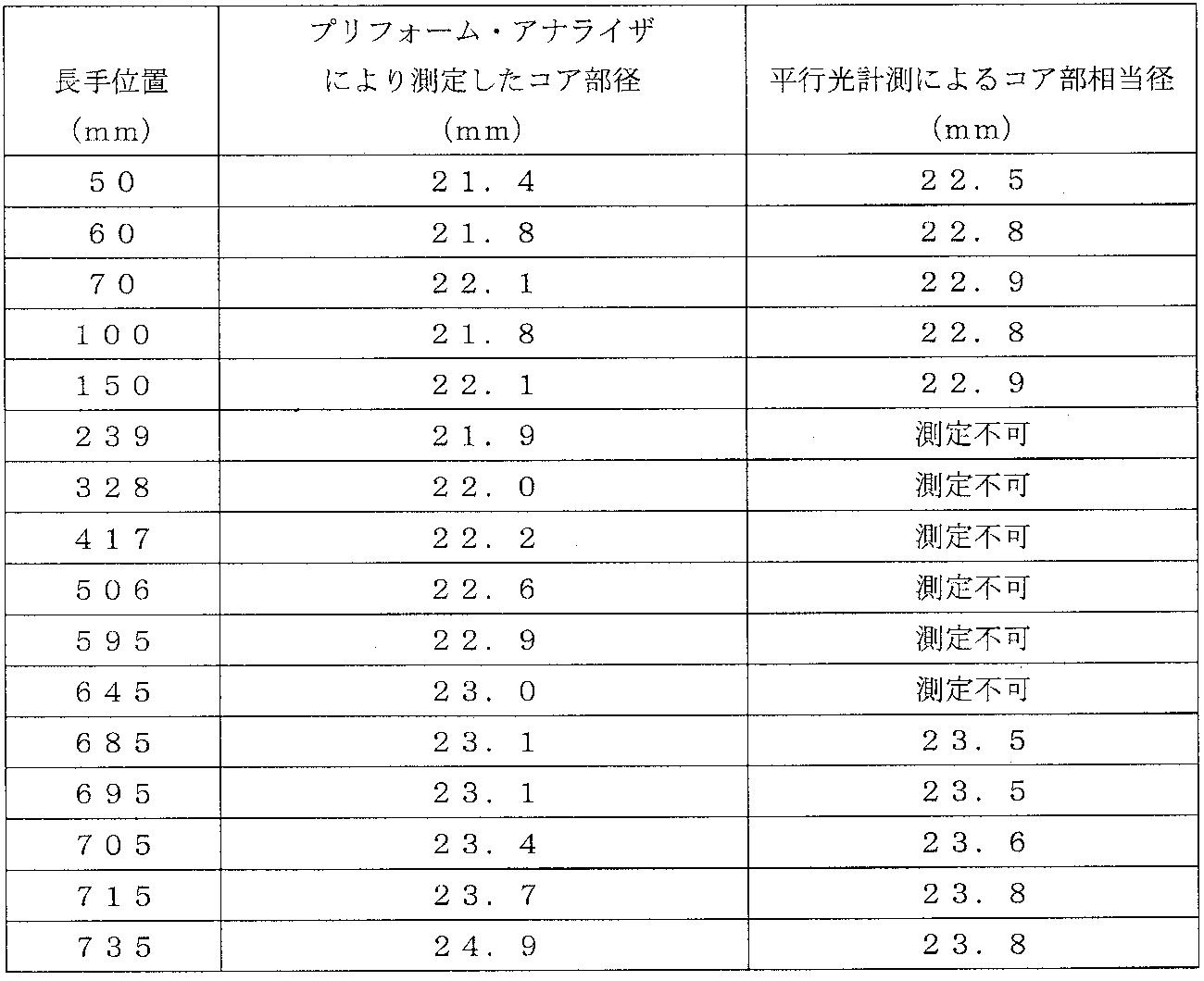
- FIG. 6 is a diagram showing a comparison of the results of measuring the core diameter by the respective measurement methods in the longitudinal direction of the optical fiber preform. As shown in the figure, also in the longitudinal direction of the optical fiber preform, the measurement result using the parallel light and the measurement result using the preform analyzer are almost the same, and the diameter of the core portion is 23 mm. With respect to the optical fiber preform that exceeds the above, it was found that the measurement result using the preform analyzer could be substituted for the measurement using the parallel light.
- Example 2 Using the same equipment as in Example 1, a glass fine particle deposit was manufactured. 8.9 L / min of oxygen, 6.7 L / min of hydrogen, 0.40 L / min of argon, 0.41 L / min of silicon tetrachloride, and 20 mL / min of germanium tetrachloride were passed through the core deposition burner 13.
- 0.91 L / min of silicon tetrachloride and 0.68 L / min of oxygen are injected into the injection port 21a of the first clad part deposition burner 14, 34L / minute of hydrogen is injected into the injection port 21d, and 18L / minute of oxygen is injected into the injection port 21f.
- Oxygen was supplied to the small-diameter injection port group 21c at a flow rate of 1.4 L / min in total.
- the injection port 21a of the second cladding deposition burner 15 is set at 5.4 L / min of silicon tetrachloride and 3.5 L / min of oxygen, 70 L / min of hydrogen at the injection port 21d, and at the injection port 21f.
- Oxygen was supplied at a flow rate of 30 L / min and the small-diameter jet group 21 c at a total flow rate of 6.3 L / min.
- the manufactured glass particle deposit was dehydrated by heating to about 1200 ° C. in a furnace tube containing chlorine gas. Then, the glass was heated to about 1500 ° C. in a furnace tube in a helium gas atmosphere to be transparently vitrified to prepare an optical fiber preform.
- the refractive index distribution was measured with a preform analyzer for a cylindrical portion having a generally stable diameter except for the tapered portions at both ends in the longitudinal direction.
- the value of the ratio R calculated in Example 1 was 0.00149 (1 / mm).
- the diameter corresponding to the core was 21.6 mm.
- Comparative Example 1 Using the same equipment as in Example 1, an optical fiber preform according to Comparative Example 1 was produced.
- the core deposition burner 13 was supplied with 9.3 L / min of oxygen, 6.5 L / min of hydrogen, 0.38 L / min of argon, 0.44 L / min of silicon tetrachloride, and 16 mL / min of germanium tetrachloride.
- ⁇ Circle around (1) 0.81 L / min of silicon tetrachloride and 0.66 L / min of oxygen flowed into the injection port 21a of the first cladding deposition burner 14.
- a flow rate of 29 L / min of hydrogen was supplied to the injection port 21d, 15 L / min of oxygen was supplied to the injection port 21f, and a total of 3.0 L / min was supplied to the small-diameter injection port group 21c.
- the injection port 21a of the second cladding deposition burner 15 is set at 4.8 L / min of silicon tetrachloride and 3.6 L / min of oxygen, 63 L / min of hydrogen at the injection port 21d, and 63 L / min of the injection port 21f.
- Oxygen was supplied at a flow rate of 6.2 L / min through the small-diameter injection port group 21 c at a total flow rate of 6.2 L / min.
- the glass particle deposit body 12 manufactured under the above conditions was heated to about 1200 ° C. in a furnace tube containing chlorine gas to be dehydrated. Thereafter, the mixture was heated to about 1500 ° C. in a furnace tube in a helium gas atmosphere to form a transparent glass, thereby producing an optical fiber preform.
- the refractive index distribution was measured with a preform analyzer for a cylindrical portion having a substantially stable diameter except for the tapered portions at both ends in the longitudinal direction.
- FIG. 7 is a graph showing the distribution of the refractive index ratio of the optical fiber preform according to Comparative Example 1 in comparison with the distribution of the refractive index ratio of the optical fiber preform according to Example 1. As shown in the figure, the refractive index ratio distributions of the two are different, reflecting the difference in the manufacturing conditions.
- the ratio R of the optical fiber preform according to Comparative Example 1 was 0.00113 (1 / mm).
- the above optical fiber preform was irradiated with parallel light from the side, and the light transmitted through the optical fiber preform was received, and the light intensity distribution of the image photographed was measured.
- the distance between the two dark portions of the light intensity distribution was defined as the core equivalent diameter of the optical fiber preform.
- the core equivalent diameter was measured at a plurality of locations in the longitudinal direction of the optical fiber preform by the same method. The measurement results are shown in Table 1 below.
- the core equivalent diameter of the optical fiber preform manufactured as a comparative example could not be measured in a part of the longitudinal direction.
- FIG. 8 is a view showing a comparison between the core equivalent diameter obtained by measurement using parallel light and the measurement result of the core diameter obtained by using a preform analyzer in Comparative Example 1 described above. As shown in the figure, the ratio of the values of the measurement results obtained by different measurement methods varied from 0.95 to 1.05, and did not become constant in the longitudinal direction.
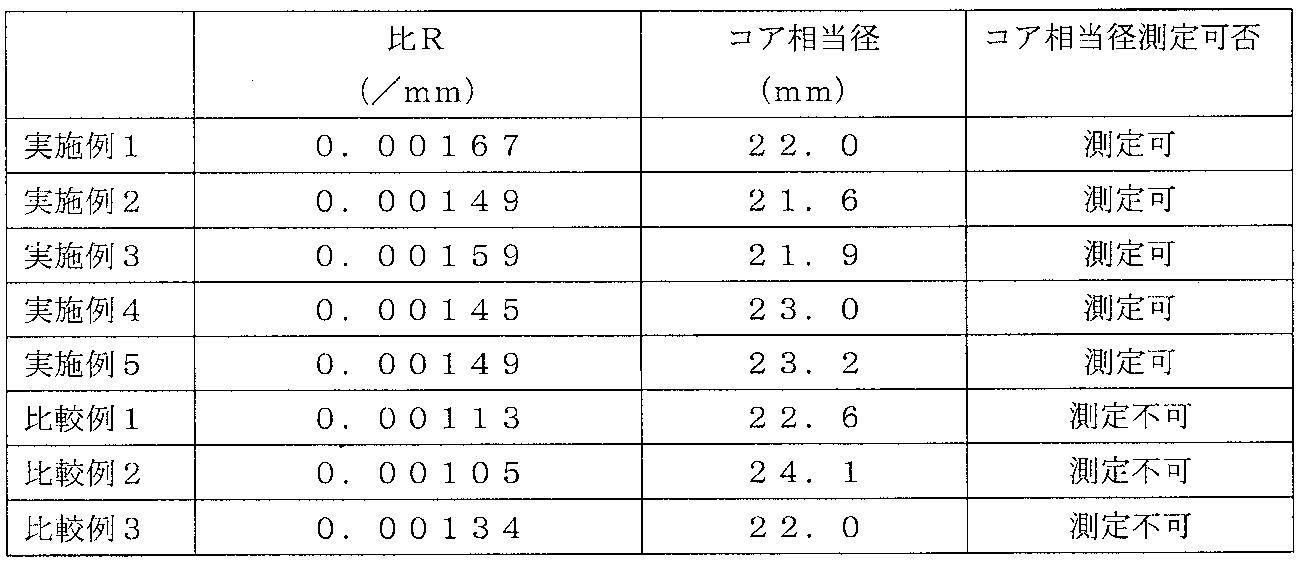
- the ratio R is 0.0015 or more
- the effective core equivalent diameter can be measured from the transmitted light intensity distribution of the parallel light.
- the value of the core equivalent diameter measured by the method using parallel light and the value of the core diameter measured by the preform analyzer are used.
- the ratio sometimes changed.
- the trade-off is whether the measurement interval is increased in the longitudinal direction of the optical fiber preform and the measurement accuracy is reduced, or the measurement time is increased by measuring at small intervals. could not be avoided.
- the relationship between the measurement result of the core equivalent diameter by the parallel light and the measurement result of the core diameter measured by the preform analyzer is stable, and is quick and easy.
- a highly reliable measurement result can be obtained. Therefore, the quality and productivity of the enlarged optical fiber preform can be improved, and the supply of the optical fiber can be improved.
Landscapes
- Chemical & Material Sciences (AREA)
- Physics & Mathematics (AREA)
- Engineering & Computer Science (AREA)
- General Physics & Mathematics (AREA)
- Optics & Photonics (AREA)
- General Life Sciences & Earth Sciences (AREA)
- General Chemical & Material Sciences (AREA)
- Life Sciences & Earth Sciences (AREA)
- Chemical Kinetics & Catalysis (AREA)
- Geochemistry & Mineralogy (AREA)
- Manufacturing & Machinery (AREA)
- Materials Engineering (AREA)
- Organic Chemistry (AREA)
- Analytical Chemistry (AREA)
- Manufacture, Treatment Of Glass Fibers (AREA)
Abstract
Description
特許文献1 特開2005-308717号公報
【一般的開示】

図1および図2に示した機材を用いてガラス微粒子堆積体12を製造した。コア部堆積用バーナ13に、酸素9.3L/分、水素6.8L/分、アルゴン0.38L/分、四塩化ケイ素0.46L/分および四塩化ゲルマニウム17mL/分を流した。

実施例1と同じ機材を用いてガラス微粒子堆積体を製造した。コア部堆積用バーナ13には、酸素8.9L/分、水素6.7L/分、アルゴン0.40L/分、四塩化ケイ素0.41L/分および四塩化ゲルマニウム20mL/分を流した。
実施例1と同じ機材を用いて、比較例1に係る光ファイバ母材を作成した。コア部堆積用バーナ13には、酸素9.3L/分、水素6.5L/分、アルゴン0.38L/分、四塩化ケイ素0.44L/分および四塩化ゲルマニウム16mL/分を流した。
更に、比Rが異なる複数の実施例および比較例を作成して、平行光の照射によるコア相当径の測定の可否について調べた。結果を下記の表2にまとめて示す。
Claims (3)
- 屈折率が相対的に高いコア部と屈折率が相対的に低いクラッド部とを有する光ファイバ母材であって、
前記光ファイバ母材の半径方向について屈折率が変化する前記コア部から前記クラッド部に至る区間において、前記クラッド部の屈折率を屈折率比の基準0.0とし、前記コア部の屈折率の最大値を屈折率比1.0として、
前記光ファイバ母材の径方向について、前記屈折率比が0.25となる第1の位置の前記光ファイバ母材の屈折率と、前記屈折率比が0.75となる第2の位置の前記光ファイバ母材の屈折率との間の差と、前記第1の位置および前記第2の位置の間隔(mm)との比の絶対値を下記の式1に従って算出した場合に0.0015(/mm)以上である光ファイバ母材。

- 前記光ファイバ母材は、前記第1の位置よりも外周側に、前記光ファイバ母材の径方向について屈折率の変化を示す曲線が変曲点を生じる屈折率分布を有する請求項1に記載の光ファイバ母材。
- 前記光ファイバ母材が略円筒形状になる部分のコア部相当径が直径で22mm以上である請求項1または2に記載の光ファイバ母材。
Priority Applications (4)
| Application Number | Priority Date | Filing Date | Title |
|---|---|---|---|
| JP2020547477A JP7068484B2 (ja) | 2018-09-28 | 2019-09-30 | 光ファイバ母材の測定方法 |
| CN201980061866.4A CN112805254B (zh) | 2018-09-28 | 2019-09-30 | 光纤母材 |
| KR1020217008467A KR102434616B1 (ko) | 2018-09-28 | 2019-09-30 | 광파이버 모재 |
| US17/213,213 US11274917B2 (en) | 2018-09-28 | 2021-03-25 | Method of measuring optical fiber preform |
Applications Claiming Priority (2)
| Application Number | Priority Date | Filing Date | Title |
|---|---|---|---|
| JP2018183352 | 2018-09-28 | ||
| JP2018-183352 | 2018-09-28 |
Related Child Applications (1)
| Application Number | Title | Priority Date | Filing Date |
|---|---|---|---|
| US17/213,213 Continuation US11274917B2 (en) | 2018-09-28 | 2021-03-25 | Method of measuring optical fiber preform |
Publications (1)
| Publication Number | Publication Date |
|---|---|
| WO2020065632A1 true WO2020065632A1 (ja) | 2020-04-02 |
Family
ID=69951882
Family Applications (1)
| Application Number | Title | Priority Date | Filing Date |
|---|---|---|---|
| PCT/IB2019/058290 Ceased WO2020065632A1 (ja) | 2018-09-28 | 2019-09-30 | 光ファイバ母材 |
Country Status (5)
| Country | Link |
|---|---|
| US (1) | US11274917B2 (ja) |
| JP (1) | JP7068484B2 (ja) |
| KR (1) | KR102434616B1 (ja) |
| CN (1) | CN112805254B (ja) |
| WO (1) | WO2020065632A1 (ja) |
Families Citing this family (2)
| Publication number | Priority date | Publication date | Assignee | Title |
|---|---|---|---|---|
| JP7399835B2 (ja) * | 2020-10-07 | 2023-12-18 | 信越化学工業株式会社 | 光ファイバ用多孔質ガラス堆積体の製造方法 |
| WO2023219116A1 (ja) * | 2022-05-10 | 2023-11-16 | 信越化学工業株式会社 | 光ファイバ母材及び光ファイバ母材の製造方法 |
Citations (9)
| Publication number | Priority date | Publication date | Assignee | Title |
|---|---|---|---|---|
| JPH0925135A (ja) * | 1995-07-12 | 1997-01-28 | Samsung Electron Co Ltd | 揮発性錯体を用いた希土類元素添加光ファイバーの製造方法 |
| JP2003054976A (ja) * | 2001-08-17 | 2003-02-26 | Sumitomo Electric Ind Ltd | ガラス微粒子堆積体の製造方法 |
| JP2003206152A (ja) * | 2001-11-09 | 2003-07-22 | Fujikura Ltd | 光ファイバ、光ファイバ母材およびそれらの製造方法 |
| JP2006292843A (ja) * | 2005-04-06 | 2006-10-26 | Shin Etsu Chem Co Ltd | 光ファイバの製造方法 |
| US20070137256A1 (en) * | 2005-12-19 | 2007-06-21 | Barish Eric L | Methods for optical fiber manufacture |
| JP2013234078A (ja) * | 2012-05-02 | 2013-11-21 | Shin-Etsu Chemical Co Ltd | 光ファイバ用多孔質ガラス堆積体の製造方法 |
| JP2014142613A (ja) * | 2012-12-28 | 2014-08-07 | Shin Etsu Chem Co Ltd | 光ファイバおよび光ファイバ用シリカガラス母材 |
| CN104876434A (zh) * | 2015-03-10 | 2015-09-02 | 武汉理工大学 | 一种均匀掺杂石英玻璃棒的制备方法 |
| JP2016196388A (ja) * | 2015-04-06 | 2016-11-24 | 信越化学工業株式会社 | 多孔質ガラス母材の製造方法 |
Family Cites Families (16)
| Publication number | Priority date | Publication date | Assignee | Title |
|---|---|---|---|---|
| US4307296A (en) * | 1980-04-14 | 1981-12-22 | Bell Telephone Laboratories, Incorporated | Method of observing the core region of optical fibers and preforms |
| US4362943A (en) * | 1980-09-08 | 1982-12-07 | Bell Telephone Laboratories, Incorporated | Method of measuring the refractive index profile and the core diameter of optical fibers and preforms |
| CN1138690A (zh) * | 1995-11-08 | 1996-12-25 | 重庆大学 | 一种横向前射光光纤几何参数和折射率分布测量方法 |
| TWI233430B (en) * | 2000-01-28 | 2005-06-01 | Shinetsu Chemical Co | Method for manufacturing glass base material, glass base material, and optical fiber |
| US6807350B2 (en) * | 2001-07-17 | 2004-10-19 | Verrillon, Inc. | Optical fiber with a radially varying index of refraction and related methods |
| JP3986842B2 (ja) * | 2001-07-26 | 2007-10-03 | 株式会社フジクラ | ノンゼロ分散シフト光ファイバ用光ファイバ母材の製法 |
| JP2003238203A (ja) * | 2002-02-15 | 2003-08-27 | Furukawa Electric Co Ltd:The | 石英光ファイバおよび石英光ファイバ母材の製造方法 |
| JP2003277069A (ja) * | 2002-03-22 | 2003-10-02 | Fujikura Ltd | 多孔質母材の製造方法 |
| JP4056778B2 (ja) * | 2002-04-04 | 2008-03-05 | 株式会社フジクラ | 光ファイバ母材の製造方法 |
| CN1310045C (zh) * | 2002-10-01 | 2007-04-11 | 古河电气工业株式会社 | 光纤、光传送线路以及光纤的制造方法 |
| EP1657575A4 (en) * | 2003-04-11 | 2008-03-19 | Fujikura Ltd | OPTICAL FIBER |
| CN100567930C (zh) * | 2004-03-23 | 2009-12-09 | 信越化学工业株式会社 | 光纤母材的芯部不圆度的测量方法及其装置 |
| JP2005308717A (ja) | 2004-03-23 | 2005-11-04 | Shin Etsu Chem Co Ltd | 光ファイバ母材のコア部非円率の測定方法及びその装置 |
| JP4233098B2 (ja) * | 2005-05-31 | 2009-03-04 | 信越化学工業株式会社 | 光ファイバ用母材の構造測定方法と測定装置 |
| US9975802B2 (en) * | 2013-05-31 | 2018-05-22 | Corning Incorporated | Method for making low bend loss optical fiber preforms |
| RU2736023C2 (ru) * | 2015-12-22 | 2020-11-11 | Корнинг Инкорпорейтед | Легированное бромом оптическое волокно |
-
2019
- 2019-09-30 KR KR1020217008467A patent/KR102434616B1/ko active Active
- 2019-09-30 CN CN201980061866.4A patent/CN112805254B/zh active Active
- 2019-09-30 JP JP2020547477A patent/JP7068484B2/ja active Active
- 2019-09-30 WO PCT/IB2019/058290 patent/WO2020065632A1/ja not_active Ceased
-
2021
- 2021-03-25 US US17/213,213 patent/US11274917B2/en active Active
Patent Citations (9)
| Publication number | Priority date | Publication date | Assignee | Title |
|---|---|---|---|---|
| JPH0925135A (ja) * | 1995-07-12 | 1997-01-28 | Samsung Electron Co Ltd | 揮発性錯体を用いた希土類元素添加光ファイバーの製造方法 |
| JP2003054976A (ja) * | 2001-08-17 | 2003-02-26 | Sumitomo Electric Ind Ltd | ガラス微粒子堆積体の製造方法 |
| JP2003206152A (ja) * | 2001-11-09 | 2003-07-22 | Fujikura Ltd | 光ファイバ、光ファイバ母材およびそれらの製造方法 |
| JP2006292843A (ja) * | 2005-04-06 | 2006-10-26 | Shin Etsu Chem Co Ltd | 光ファイバの製造方法 |
| US20070137256A1 (en) * | 2005-12-19 | 2007-06-21 | Barish Eric L | Methods for optical fiber manufacture |
| JP2013234078A (ja) * | 2012-05-02 | 2013-11-21 | Shin-Etsu Chemical Co Ltd | 光ファイバ用多孔質ガラス堆積体の製造方法 |
| JP2014142613A (ja) * | 2012-12-28 | 2014-08-07 | Shin Etsu Chem Co Ltd | 光ファイバおよび光ファイバ用シリカガラス母材 |
| CN104876434A (zh) * | 2015-03-10 | 2015-09-02 | 武汉理工大学 | 一种均匀掺杂石英玻璃棒的制备方法 |
| JP2016196388A (ja) * | 2015-04-06 | 2016-11-24 | 信越化学工業株式会社 | 多孔質ガラス母材の製造方法 |
Also Published As
| Publication number | Publication date |
|---|---|
| JPWO2020065632A1 (ja) | 2021-09-16 |
| JP7068484B2 (ja) | 2022-05-16 |
| KR102434616B1 (ko) | 2022-08-19 |
| KR20210048518A (ko) | 2021-05-03 |
| US20210215473A1 (en) | 2021-07-15 |
| CN112805254A (zh) | 2021-05-14 |
| US11274917B2 (en) | 2022-03-15 |
| CN112805254B (zh) | 2024-10-29 |
Similar Documents
| Publication | Publication Date | Title |
|---|---|---|
| JP2007230862A (ja) | ディプレスト・インデックス光ファイバの製造 | |
| US3932160A (en) | Method for forming low loss optical waveguide fibers | |
| WO2020065632A1 (ja) | 光ファイバ母材 | |
| US8820121B2 (en) | Method of manufacturing optical fiber base material | |
| US6823125B2 (en) | Optical fiber base material, its manufacturing method and optical fiber | |
| WO2021037248A1 (zh) | 光纤预制棒及其制备方法、等离子沉积设备 | |
| US20150040616A1 (en) | Optical fiber glass base material manufacturing method and optical fiber glass base material | |
| KR100426394B1 (ko) | 외부증착공법을 이용한 대형 프리폼 제조시에 증착입자를제어하는 방법 및 장치 | |
| JP7286587B2 (ja) | 光ファイバ母材 | |
| JPS638707A (ja) | 分散シフト光フアイバ | |
| JP6431349B2 (ja) | 光ファイバ母材の製造方法 | |
| JP3562545B2 (ja) | 光ファイバ用ガラス母材の製造方法 | |
| JPH087284B2 (ja) | 漏洩光フアイバとその製造方法 | |
| JP2013056786A (ja) | 光ファイバ用母材の製造方法 | |
| JP2009114045A (ja) | 光ファイバ用ガラス母材の製造方法 | |
| EP4524116A1 (en) | Optical fiber preform and method for producing optical fiber preform | |
| CN115650578B (zh) | 用于抑制sbs的轴向成分周期性变化的光纤及其制备方法 | |
| KR100641941B1 (ko) | 길이방향으로 균일성을 갖는 기가비트급 전송시스템용다중모드 광섬유의 제조방법 | |
| KR830002121B1 (ko) | 광 파이버 | |
| US20220009816A1 (en) | Optical fiber preform | |
| KR101287545B1 (ko) | 유효면적이 증가된 분산이동 광섬유용 모재의 제조방법 | |
| CN119707275A (zh) | 一种折射率阶越式套管及其制备方法、制造设备 | |
| US20070147753A1 (en) | Optical fiber and method for fabricating same | |
| JP2017043512A (ja) | 光ファイバ母材の製造方法、光ファイバの製造方法およびレンズの製造方法 | |
| JP2003277069A (ja) | 多孔質母材の製造方法 |
Legal Events
| Date | Code | Title | Description |
|---|---|---|---|
| 121 | Ep: the epo has been informed by wipo that ep was designated in this application |
Ref document number: 19867867 Country of ref document: EP Kind code of ref document: A1 |
|
| ENP | Entry into the national phase |
Ref document number: 2020547477 Country of ref document: JP Kind code of ref document: A |
|
| ENP | Entry into the national phase |
Ref document number: 20217008467 Country of ref document: KR Kind code of ref document: A |
|
| NENP | Non-entry into the national phase |
Ref country code: DE |
|
| 122 | Ep: pct application non-entry in european phase |
Ref document number: 19867867 Country of ref document: EP Kind code of ref document: A1 |