WO2020054752A1 - 冷却装置および冷却装置を用いた冷却システム - Google Patents
冷却装置および冷却装置を用いた冷却システム Download PDFInfo
- Publication number
- WO2020054752A1 WO2020054752A1 PCT/JP2019/035632 JP2019035632W WO2020054752A1 WO 2020054752 A1 WO2020054752 A1 WO 2020054752A1 JP 2019035632 W JP2019035632 W JP 2019035632W WO 2020054752 A1 WO2020054752 A1 WO 2020054752A1
- Authority
- WO
- WIPO (PCT)
- Prior art keywords
- container
- refrigerant
- cooling device
- heat
- phase
- Prior art date
- Legal status (The legal status is an assumption and is not a legal conclusion. Google has not performed a legal analysis and makes no representation as to the accuracy of the status listed.)
- Ceased
Links
Images




Classifications
-
- F—MECHANICAL ENGINEERING; LIGHTING; HEATING; WEAPONS; BLASTING
- F28—HEAT EXCHANGE IN GENERAL
- F28D—HEAT-EXCHANGE APPARATUS, NOT PROVIDED FOR IN ANOTHER SUBCLASS, IN WHICH THE HEAT-EXCHANGE MEDIA DO NOT COME INTO DIRECT CONTACT
- F28D1/00—Heat-exchange apparatus having stationary conduit assemblies for one heat-exchange medium only, the media being in contact with different sides of the conduit wall, in which the other heat-exchange medium is a large body of fluid, e.g. domestic or motor car radiators
- F28D1/06—Heat-exchange apparatus having stationary conduit assemblies for one heat-exchange medium only, the media being in contact with different sides of the conduit wall, in which the other heat-exchange medium is a large body of fluid, e.g. domestic or motor car radiators with the heat-exchange conduits forming part of, or being attached to, the tank containing the body of fluid
-
- F—MECHANICAL ENGINEERING; LIGHTING; HEATING; WEAPONS; BLASTING
- F28—HEAT EXCHANGE IN GENERAL
- F28D—HEAT-EXCHANGE APPARATUS, NOT PROVIDED FOR IN ANOTHER SUBCLASS, IN WHICH THE HEAT-EXCHANGE MEDIA DO NOT COME INTO DIRECT CONTACT
- F28D15/00—Heat-exchange apparatus with the intermediate heat-transfer medium in closed tubes passing into or through the conduit walls ; Heat-exchange apparatus employing intermediate heat-transfer medium or bodies
- F28D15/02—Heat-exchange apparatus with the intermediate heat-transfer medium in closed tubes passing into or through the conduit walls ; Heat-exchange apparatus employing intermediate heat-transfer medium or bodies in which the medium condenses and evaporates, e.g. heat pipes
- F28D15/04—Heat-exchange apparatus with the intermediate heat-transfer medium in closed tubes passing into or through the conduit walls ; Heat-exchange apparatus employing intermediate heat-transfer medium or bodies in which the medium condenses and evaporates, e.g. heat pipes with tubes having a capillary structure
-
- F—MECHANICAL ENGINEERING; LIGHTING; HEATING; WEAPONS; BLASTING
- F28—HEAT EXCHANGE IN GENERAL
- F28F—DETAILS OF HEAT-EXCHANGE AND HEAT-TRANSFER APPARATUS, OF GENERAL APPLICATION
- F28F1/00—Tubular elements; Assemblies of tubular elements
- F28F1/10—Tubular elements and assemblies thereof with means for increasing heat-transfer area, e.g. with fins, with projections, with recesses
- F28F1/12—Tubular elements and assemblies thereof with means for increasing heat-transfer area, e.g. with fins, with projections, with recesses the means being only outside the tubular element
-
- F—MECHANICAL ENGINEERING; LIGHTING; HEATING; WEAPONS; BLASTING
- F28—HEAT EXCHANGE IN GENERAL
- F28F—DETAILS OF HEAT-EXCHANGE AND HEAT-TRANSFER APPARATUS, OF GENERAL APPLICATION
- F28F1/00—Tubular elements; Assemblies of tubular elements
- F28F1/10—Tubular elements and assemblies thereof with means for increasing heat-transfer area, e.g. with fins, with projections, with recesses
- F28F1/40—Tubular elements and assemblies thereof with means for increasing heat-transfer area, e.g. with fins, with projections, with recesses the means being only inside the tubular element
-
- F—MECHANICAL ENGINEERING; LIGHTING; HEATING; WEAPONS; BLASTING
- F28—HEAT EXCHANGE IN GENERAL
- F28F—DETAILS OF HEAT-EXCHANGE AND HEAT-TRANSFER APPARATUS, OF GENERAL APPLICATION
- F28F21/00—Constructions of heat-exchange apparatus characterised by the selection of particular materials
- F28F21/02—Constructions of heat-exchange apparatus characterised by the selection of particular materials of carbon, e.g. graphite
-
- F—MECHANICAL ENGINEERING; LIGHTING; HEATING; WEAPONS; BLASTING
- F28—HEAT EXCHANGE IN GENERAL
- F28F—DETAILS OF HEAT-EXCHANGE AND HEAT-TRANSFER APPARATUS, OF GENERAL APPLICATION
- F28F21/00—Constructions of heat-exchange apparatus characterised by the selection of particular materials
- F28F21/08—Constructions of heat-exchange apparatus characterised by the selection of particular materials of metal
Definitions
- the present invention relates to a cooling device for cooling electric / electronic components and the like, and more particularly to a cooling device capable of cooling electric / electronic components and the like having a large calorific value to a predetermined allowable temperature without increasing the size of the cooling device. .
- heating elements such as electric and electronic components are mounted at a high density inside the electronic devices, and the amount of heat generated by the heating elements is increasing. If the temperature of a heating element such as an electric or electronic component rises above a predetermined allowable temperature, it may cause malfunction of the electric or electronic component or the like. It is important to keep it below the allowable temperature. Therefore, a cooling device for cooling electric / electronic parts and the like is mounted inside the electronic device.
- the cooling device is required to further improve the cooling characteristics while avoiding an increase in size.
- a liquid chamber also serving as a liquid storage tank a vapor pipe is connected, a first part defining the vapor chamber, and a liquid pipe is connected to one side, the heat conductivity is lower than the first part,
- Patent Document 1 A loop heat pipe using an evaporator having a case having the following has been proposed (Patent Document 1).
- the cooling performance is improved by smoothing a phase change of a working fluid from a liquid phase to a gas phase by using a porous body having a plurality of cylindrical protrusions.
- Patent Document 1 which is a loop heat pipe
- the working fluid that has received heat from the heating element and changed phase from the liquid phase to the gas phase in the steamer is carried out from the steamer to a radiating fin portion that is a heat exchange means.
- the heat is exchanged by the radiating fins and the heat is radiated to the radiating fins, and the phase changes from a gas phase to a liquid phase.
- the heat exchange function of the heat radiation fins depends on the cooling air supplied to the heat radiation fins, it is necessary to increase the fin area, that is, enlarge the device, in order to improve the heat exchange function of the heat radiation fins Becomes Therefore, in the loop heat pipe as disclosed in Patent Document 1, there is room for improvement in improving the cooling characteristics while avoiding an increase in size.
- a gas-phase working fluid in a steamer is conveyed out of the steamer and exchanges heat to change into a liquid phase, and the liquid-phase working fluid radiates heat. Reflux into the steamer from the fin. Therefore, in the loop heat pipe as disclosed in Patent Document 1, there is room for improvement in the cooling characteristics in that it is not easy to control the flow of the working fluid.
- an object of the present invention is to provide a cooling device capable of exhibiting excellent cooling characteristics while avoiding an increase in the size of the device, and a cooling system using the cooling device.
- the gist of the configuration of the cooling device of the present invention and the cooling system using the cooling device is as follows. [1] A container to which at least one heating element is thermally connected, a primary refrigerant sealed in the container, and a condensing tube through which a secondary refrigerant flows through a gas phase portion inside the container, Cooling device with. [2] The heating element according to [1], wherein the heating element is thermally connected to a portion of the outer surface of the container where the liquid-phase primary refrigerant is present or near a portion where the liquid-phase primary refrigerant is present. Cooling system.
- the cooling device according to [6], wherein the heat conductive member is a metal member or a carbon member.
- the device according to any one of [3] to [7], wherein at least a part of the container inner surface area increasing portion is a sintered body of a heat conductive material or an aggregate of a particulate heat conductive material. Cooling system.
- the sintered body of the heat conductive material is a metal sintered body, and the metal sintered body is selected from the group consisting of metal powder, metal fiber, metal mesh, metal braid, and metal foil.
- the cooling device according to [8], wherein the cooling device is a sintered body of at least one metal material.
- the cooling device according to [8], wherein the aggregate of the particulate heat conductive material is an aggregate of carbon particles.
- a condensing tube outer surface surface area increasing portion for increasing a contact area of the gas phase with the primary refrigerant is formed on an outer surface of the condensing tube. apparatus.
- a condensing tube inner surface area increasing portion that increases a contact area with the secondary refrigerant is formed on an inner surface of the condensing tube.
- a plurality of the condensation tubes are arranged in parallel.
- the shape perpendicular to the longitudinal direction in at least a part of the region is the shape perpendicular to the longitudinal direction of the condenser tube outside the container,
- the cooling device according to any one of [1] to [17].
- the condensing pipe is further provided with a secondary refrigerant storage block for storing the secondary refrigerant, and the secondary refrigerant storage block is thermally connected to the container [1] to [1].
- the primary refrigerant that has received heat from the heating element changes its phase from a liquid phase to a gaseous phase, and the primary refrigerant in a gaseous phase exchanges heat with the condensing tube.
- phase change from the gas phase to the liquid phase heat is transmitted from the primary refrigerant to the secondary refrigerant flowing through the condenser tube, and the secondary refrigerant to which the heat has been transmitted passes through the condenser tube to the secondary refrigerant.
- a cooling system that circulates to a secondary refrigerant cooling unit is cooled to a predetermined temperature, and is cooled by the secondary refrigerant cooling unit, and the secondary refrigerant circulates through the condensing tube and returns to the cooling device.
- a first container a primary refrigerant sealed in the first container, a condensing pipe through which a secondary refrigerant flows through a gas phase portion inside the first container,
- a heat transport member connected to the container of The heat transport member has a second container to which at least one heating element is thermally connected, an extension having an internal space communicating with the inside of the second container, and an inside of the heat transport member.
- a sealed tertiary refrigerant wherein the extension portion is in contact with the liquid-phase primary refrigerant.
- a first container a primary refrigerant sealed in the first container, a condensing tube through which a secondary refrigerant flows through a gas phase portion inside the first container,
- a heat transport member connected to the container of The heat transport member has a second container to which at least one heating element is thermally connected, and a tertiary refrigerant sealed inside the second container, wherein the second container is A cooling device in contact with the liquid-phase primary refrigerant.
- a heat transport member connected to the container of The heat transport member includes: a base block to which at least one heating element is thermally connected; a heat pipe section erected on the base block; and a tertiary refrigerant sealed inside the heat pipe section.
- a first container a primary refrigerant sealed in the first container, a condensing tube through which a secondary refrigerant flows through a gas phase portion inside the first container,
- a heat transport member connected to the container of A cooling device, wherein the heat transport member includes a base block to which at least one heating element is thermally connected, a heat pipe embedded in the base block, and a tertiary refrigerant sealed inside the heat pipe.
- the cooling device according to [22] wherein the second container is in contact with the primary refrigerant in a liquid phase.
- the heating element is thermally connected to a portion of the outer surface of the second container where the liquid-phase tertiary refrigerant is present or near a portion where the liquid-phase tertiary refrigerant is present [22] ] Or the cooling device according to [23].
- a second container inner surface area increasing portion for increasing a contact area of the liquid phase with the tertiary refrigerant is formed on an inner surface of the second container to which the heating element is thermally connected [22]. ] Or the cooling device according to [23].
- the heat transport member outer surface area increasing portion for increasing a contact area of the liquid phase with the primary refrigerant is formed on an outer surface of the second container and / or the extension portion according to [22].
- Cooling system [31] The cooling device according to [23], wherein a heat transport member outer surface surface area increasing portion for increasing a contact area of the liquid phase with the primary refrigerant is formed on an outer surface of the second container. [32] The cooling device according to [24], wherein a heat transport member outer surface surface area increasing portion for increasing a contact area of the liquid phase with the primary refrigerant is formed on an outer surface of the heat pipe portion. [33] The cooling device according to any one of [30] to [32], wherein the heat transport member outer surface surface area increasing portion has an uneven portion. [34] The cooling device according to [33], wherein the uneven portion has a sintered body of a metal wire and / or a sintered body of a metal powder.
- the shape of the condensation tube inside the first container in a direction perpendicular to the longitudinal direction in at least a part of the region is perpendicular to the longitudinal direction of the condensation tube outside the first container.
- a secondary refrigerant storage block for storing the secondary refrigerant is further provided in the condensing tube, and the secondary refrigerant storage block is thermally connected to the first container [22]. ]
- a radiation fin is further provided on an outer surface of the first container.
- a first container a primary refrigerant sealed in the first container, a condensing pipe through which a secondary refrigerant flows through a gas phase portion inside the first container, And a heat transport member connected to the second container, wherein the heat transport member has a second container to which at least one heating element is thermally connected, and an inner portion communicating with the inside of the second container.
- An extending portion having a space, a tertiary refrigerant sealed inside the heat transport member, the extending portion, a cooling device in contact with the liquid-phase primary refrigerant, from the cooling device
- a secondary refrigerant cooling unit to which the extended condensing tube is connected is used, and the condensing tube circulates the cooling device and the secondary refrigerant cooling unit.
- the tertiary refrigerant received from the heating element changes its phase from a liquid phase to a gaseous phase, and the tertiary refrigerant in a gaseous phase is the second refrigerant.
- the heat is transferred from the tertiary refrigerant to the primary refrigerant by flowing from the inside of the container toward the inside of the extending portion and undergoing a phase change from a gaseous phase to a liquid phase by a heat exchange action with the primary refrigerant.
- the primary refrigerant to which heat has been transferred from the tertiary refrigerant, undergoes a phase change from a liquid phase to a gaseous phase inside the first container, and the primary refrigerant in a gaseous phase is converted from a gaseous phase to a liquid by a heat exchange action of the condensing tube.
- phase change to the phase heat is transmitted from the primary refrigerant to the secondary refrigerant flowing through the condensing tube, and the secondary refrigerant to which the heat has been transmitted passes the condensing tube to the secondary refrigerant cooling unit.
- the secondary refrigerant cooling unit Before being circulated and cooled to a predetermined temperature, and cooled by the secondary refrigerant cooling unit. Cooling system for reflux to the cooler secondary refrigerant is circulated to the condenser tube.
- a first container a primary refrigerant sealed in the first container, a condensing pipe through which a secondary refrigerant flows through a gas phase portion in the first container, And a heat transport member connected to the container, wherein the heat transport member is sealed inside the second container to which at least one heating element is thermally connected.
- a refrigeration device having a tertiary refrigerant, wherein the second container is in contact with the liquid-phase primary refrigerant, and a secondary refrigerant cooling unit to which the condensing tube extending from the cooling device is connected.
- the tertiary refrigerant received from the heating element changes its phase from a liquid phase to a gaseous phase, and the tertiary refrigerant in a gaseous phase is the second refrigerant.
- the primary refrigerant changes a phase from a liquid phase to a gas phase inside the first container, and the primary refrigerant in a gas phase changes phase from a gas phase to a liquid phase by a heat exchange action of the condensing tube.
- the heat is transmitted from the primary refrigerant to the secondary refrigerant flowing through the condensing tube, and the secondary refrigerant to which the heat is transmitted flows through the condensing tube to the secondary refrigerant cooling unit and cools to a predetermined temperature.
- the secondary refrigerant cooled in the secondary refrigerant cooling unit is condensed Cooling system for reflux to the cooling device and flowing.
- a first container a primary refrigerant sealed in the first container, a condensing tube through which a secondary refrigerant flows through a gas phase part in the first container, And a heat transport member connected to the container, wherein the heat transport member is a base block to which at least one heating element is thermally connected, and a heat pipe section erected on the base block.
- a cooling system in which the condensing tube circulates through the cooling device and the secondary refrigerant cooling unit.
- Heat is transmitted from the base block thermally connected to the heating element to the heat pipe portion, and the tertiary refrigerant sealed in the heat pipe portion that has received heat from the base block changes phase from a liquid phase to a gas phase. Then, the tertiary refrigerant in the gas phase flows through the inside of the heat pipe portion and undergoes a phase change from a gas phase to a liquid phase by a heat exchange action with the primary refrigerant, whereby heat is transferred from the tertiary refrigerant to the primary refrigerant.
- the primary refrigerant to which heat is transmitted from the tertiary refrigerant, undergoes a phase change from a liquid phase to a gaseous phase inside the first container, and the primary refrigerant in a gaseous phase acts as a heat exchanger for the condensation tube.
- the phase change from the gas phase to the liquid phase heat is transmitted from the primary refrigerant to the secondary refrigerant flowing through the condenser tube, and the secondary refrigerant to which the heat has been transmitted passes through the condenser tube to the secondary refrigerant.
- a cooling system wherein said secondary refrigerant cooled in the secondary refrigerant cooling unit is refluxed to the cooling device and flowing through the condenser tubes.
- a first container a primary refrigerant sealed in the first container, a condensing pipe through which a secondary refrigerant flows through a gas phase portion inside the first container,
- a heat transport member connected to the container, wherein the heat transport member is a base block to which at least one heating element is thermally connected; a heat pipe embedded in the base block;
- a cooling device having a tertiary refrigerant enclosed in a pipe, and a secondary refrigerant cooling unit to which the condensing tube extending from the cooling device is used, wherein the condensing tube has the cooling device and the It is a cooling system that circulates with the secondary refrigerant cooling unit, Heat is transferred from the base block thermally connected to the heating element to the heat pipe, and the ter
- the gaseous tertiary refrigerant flows inside the heat pipe, heat is transmitted from the tertiary refrigerant to the primary refrigerant, and the primary refrigerant to which heat is transmitted from the tertiary refrigerant is the first container.
- the secondary refrigerant is Cooling system for reflux to the cooling device by circulation.
- the primary refrigerant enclosed in the container undergoes heat from the heating element, so that the primary refrigerant undergoes a phase change from a liquid phase to a gaseous phase.
- a phase change from a gaseous phase to a liquid phase is caused by a condensing tube through which a secondary refrigerant flows, which penetrates a gas phase portion inside the container, and latent heat released from the primary refrigerant at the time of this phase change flows through the condensing tube. It is transmitted to the secondary refrigerant.
- the secondary refrigerant that has received the latent heat from the primary refrigerant flows through the condenser tube from inside the cooling device to the outside, so that the latent heat is transported outside the cooling device.
- the secondary refrigerant that has received the latent heat is cooled by a secondary refrigerant cooling unit provided outside the cooling device.
- the tertiary refrigerant enclosed in the second container of the heat transport member receives heat from the heating element, and changes phase from a liquid phase to a gas phase
- the tertiary refrigerant that has changed to the gaseous phase flows from the inside of the second container toward the inside of the extension portion, and undergoes heat exchange with the primary refrigerant sealed inside the first container to change from the gaseous phase to the liquid phase. Changes phase.
- the latent heat released from the tertiary refrigerant during this phase change is transmitted to the primary refrigerant enclosed inside the first container.
- the primary refrigerant undergoes a phase change from a liquid phase to a gaseous phase by receiving latent heat from the tertiary refrigerant, and the primary refrigerant that has undergone a phase change to the gaseous phase penetrates the gaseous phase inside the first container.
- the flowing condensing tube changes the phase from the gas phase to the liquid phase, and the latent heat released from the primary refrigerant during this phase change is transmitted to the secondary refrigerant flowing through the condensing tube.
- the secondary refrigerant that has received the latent heat from the primary refrigerant flows through the condenser tube from inside the cooling device to the outside, so that the latent heat is transported outside the cooling device.
- the secondary refrigerant that has received the latent heat is cooled by a secondary refrigerant cooling unit provided outside the cooling device.
- plan view means a state viewed from above in the direction of gravity.
- the cooling device of the present invention a primary refrigerant sealed in a container, and a condensing pipe through which a secondary refrigerant flows through a gas phase portion in the container, the large size of the device is provided. Excellent cooling characteristics can be exhibited while avoiding the formation of the cooling medium.
- the heating element is thermally connected to a portion of the outer surface of the container where the primary refrigerant in the liquid phase exists or in the vicinity thereof, so that the heat from the heating element to the primary refrigerant is generated. Resistance can be reduced.
- the inner surface of the container to which the heating element is thermally connected is formed with the container inner surface area increasing portion that increases the contact area with the liquid-phase primary refrigerant, Heat transfer from the heating element to the primary refrigerant via the container is facilitated. Therefore, the phase change of the primary refrigerant from the liquid phase to the gas phase is promoted, and the cooling characteristics are further improved.
- At least a part of the container inner surface area increasing portion is a sintered body of the heat conductive material or an aggregate of the particulate heat conductive material, thereby increasing the container inner surface area. Since the porous portion is formed in the portion, the phase change of the primary refrigerant from the liquid phase to the gas phase is further promoted, and the cooling characteristics are further improved.
- the cooling device of the present invention since the outer surface of the condensation tube is formed with the condensation tube outer surface area increasing portion that increases the contact area with the primary refrigerant in the gas phase, the heat exchange action of the condensation tube is improved. This promotes the phase change of the primary refrigerant from the gas phase to the liquid phase. Therefore, heat transfer from the primary refrigerant to the secondary refrigerant is further promoted, and the cooling characteristics are further improved.
- the heat exchange action of the condensation tube is improved by forming the condensation tube inner surface area increasing portion that increases the contact area with the secondary refrigerant on the inner surface of the condensation tube.
- heat transfer from the primary refrigerant to the secondary refrigerant is further promoted.
- FIG. 1 (A) Drawing is a side sectional view explaining the outline of the cooling device concerning a 5th embodiment of the present invention, and (b) Drawing explains the outline of the cooling device concerning a 5th embodiment of the present invention. It is a front sectional view. It is a side sectional view explaining the outline of the cooling device concerning a 6th embodiment of the present invention. It is a perspective view explaining the outline of the cooling device concerning a 7th embodiment of the present invention. It is a side sectional view explaining the outline of the cooling device concerning an 8th embodiment of the present invention. It is a plane sectional view explaining an outline of a cooling device concerning an 8th embodiment of the present invention. It is a side sectional view explaining the outline of the cooling device concerning a 9th embodiment of the present invention.
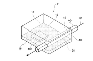
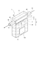
- FIG. 1 is a perspective view illustrating an outline of a cooling device according to a first embodiment of the present invention.
- FIG. 2 is a perspective view illustrating an outline of a cooling device according to a second embodiment of the present invention.
- FIG. 3 is a perspective view illustrating an outline of a cooling device according to a third embodiment of the present invention.
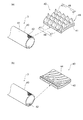
- 4A is an explanatory view in which the outer surface of a condensing tube provided in a cooling device according to a third embodiment of the present invention is enlarged
- FIG. 4B is a diagram illustrating a third embodiment of the present invention.
- FIG. 5 is a side sectional view for explaining an outline of a cooling device according to a fourth embodiment of the present invention.
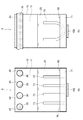
- FIG. 6A is a side cross-sectional view illustrating an outline of a cooling device according to a fifth embodiment of the present invention
- FIG. 6B is a side view of the cooling device according to the fifth embodiment of the present invention. It is a front sectional view explaining an outline.
- FIG. 7 is a side sectional view for explaining an outline of a cooling device according to a sixth embodiment of the present invention.
- FIG. 8 is a perspective view illustrating an outline of a cooling device according to a seventh embodiment of the present invention.
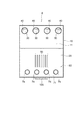
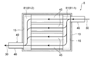
- FIG. 9 is a side sectional view for explaining an outline of a cooling device according to an eighth embodiment of the present invention.
- FIG. 10 is a cross-sectional plan view illustrating an outline of a cooling device according to an eighth embodiment of the present invention.
- FIG. 11 is a side sectional view for explaining an outline of a cooling device according to a ninth embodiment of the present invention.
- the cooling device 1 according to the first embodiment of the present invention has penetrated the container 10, the primary refrigerant 20 sealed inside the container 10, and the gas phase part 11 inside the container 10.
- the heating element 100 to be cooled is thermally connected to the outer surface 12 of the container 10 so that the heating element 100 is cooled.
- a hollow cavity 13 is formed inside the container 10.
- the cavity 13 is a space sealed with respect to the external environment, and is depressurized by degassing.
- the shape of the container 10 is a rectangular parallelepiped and has a longitudinal direction Z.
- the container 10 is installed so that the longitudinal direction Z of the container 10 is along the direction of gravity. Therefore, in the cooling device 1, the rectangular parallelepiped container 10 is installed in an upright state.
- the heating element 100 is in an upright state and is thermally connected to the side surface 14 of the container 10.
- the cooling device 1 is effective when it is necessary to install the cooling device in a space having a narrow width direction.
- the cavity 13 contains a predetermined amount of the liquid-phase primary refrigerant 20.
- the primary refrigerant 20 in the liquid phase is stored in the container 10 in such a volume that the gas phase portion 11 can be formed.
- the liquid-phase primary refrigerant 20 exists below the hollow portion 13 in the direction of gravity, and the gas-phase portion 11 in which the liquid-phase primary refrigerant 20 is not stored is formed above the hollow portion 13 in the direction of gravity.
- the connection position of the heating element 100 is not particularly limited, but in the cooling device 1, the heating element 100 is thermally connected to a portion of the outer surface 12 of the container 10 where the liquid-phase primary refrigerant 20 exists.
- connection position of the heating element 100 to the container 10 By setting the connection position of the heating element 100 to the container 10 as the above-described portion, heat transfer from the heating element 100 to the liquid-phase primary refrigerant 20 is facilitated, and the heat resistance from the heating element 100 to the primary refrigerant 20 is reduced. Can be reduced.
- the condensation tube 40 is a tubular member and penetrates the gas phase part 11 inside the container 10.
- the condensation tube 40 is located above the inner surface 15 of the container 10 in the gravity direction at a portion where the heating element 100 is thermally connected.
- the internal space of the condenser tube 40 does not communicate with the inside of the container 10 (the cavity 13). That is, the internal space of the condensation tube 40 is a space that is not communicated with the gas phase part 11 and is independent of the gas phase part 11.
- the condenser tube 40 is not in contact with the primary refrigerant 20 of the liquid phase stored on the lower side in the direction of gravity. That is, the primary refrigerant 20 in the liquid phase is not in contact with the condensation tube 40 in which the secondary refrigerant is stored.
- the outer surface 41 of the condenser tube 40 may be provided with a portion that increases the surface area of the outer surface 41 of the condenser tube 40 such as unevenness (condenser tube outer surface surface area increasing portion) or may be a smooth surface.
- the inner surface 42 of the condenser tube 40 may be formed with a portion (such as an uneven portion) that increases the surface area of the inner surface 42 of the condenser tube 40 (condensation tube inner surface surface area increasing portion) or may be a smooth surface.
- the outer surface 41 of the condenser tube 40 and the inner surface 42 of the condenser tube 40 are both smooth surfaces.
- a through-hole is formed at a portion corresponding to the gas-phase portion 11, and the condenser tube 40 is inserted into the through-hole. Is attached to the container 10.
- the number of the condenser tubes 40 is not particularly limited, and the cooling device 1 is provided with one condenser tube 40.
- the radial cross section of the condenser tube 40 is substantially circular.
- the liquid-phase secondary refrigerant 30 flows in the condenser tube 40 in a certain direction along the extending direction of the condenser tube 40. Therefore, the secondary refrigerant 30 flows through the gas phase part 11 through the wall surface of the condensation tube 40.
- the secondary refrigerant 30 is cooled to a liquid temperature lower than the allowable maximum temperature of the heating element 100, for example.
- the material of the container 10 is not particularly limited, and a wide variety of materials can be used, and examples thereof include copper, copper alloy, aluminum, aluminum alloy, nickel, nickel alloy, stainless steel, titanium, and titanium alloy.
- the material of the condenser tube 40 is not particularly limited, and examples thereof include copper, copper alloy, aluminum, aluminum alloy, nickel, nickel alloy, stainless steel, titanium, and titanium alloy.
- the primary refrigerant is not particularly limited, and a wide variety of materials can be used, and examples thereof include an electrically insulating refrigerant. Specific examples include, for example, water, fluorocarbons, cyclopentane, ethylene glycol, and mixtures thereof.
- the secondary refrigerant is not particularly limited, and includes, for example, water, antifreeze (the main component is, for example, ethylene glycol) and the like.
- the primary refrigerant 20 in the liquid phase stored in the hollow portion 13 of the container 10 receives heat from the heating element 100, the primary refrigerant 20 changes from a liquid phase to a gaseous phase and absorbs the heat from the heating element 100 as latent heat.
- the primary refrigerant that has changed to the gaseous phase moves upward in the direction of gravity in the internal space of the container 10 and flows into the gaseous phase part 11 of the container 10.
- the low-temperature secondary refrigerant 30 is circulating in the condensation tube 40 penetrating the gas phase part 11. Since the low-temperature secondary refrigerant 30 flows through the condenser tube 40, the condenser tube 40 arranged in the gas phase part 11 exhibits a heat exchange action.
- the primary refrigerant which has changed into a gaseous phase, contacts or approaches the outer surface 41 of the condensing tube 40, thereby releasing latent heat by the heat exchange action of the condensing tube 40, and changing from the gaseous phase to the liquid phase.
- the latent heat released from the primary refrigerant during the phase change from the gas phase to the liquid phase is transmitted to the secondary refrigerant 30 flowing through the condenser 40.
- the primary refrigerant that has changed to the liquid phase returns to the liquid phase primary refrigerant 20 from the gas phase portion 11 downward in the direction of gravity due to gravity.
- the primary refrigerant 20 repeats the phase change from the liquid phase to the gas phase and from the gas phase to the liquid phase in the internal space of the container 10.
- the primary refrigerant 20 changes the phase from the liquid phase to the gas phase and from the gas phase to the liquid phase in the internal space of the container 10. It is not necessary to form a circulation path for the primary refrigerant 20 such as a partition plate when repeating the above. Therefore, the structure of the container 10 can be simplified.
- a cooling system using the cooling device 1 will be described.
- the cooling device 1 and a secondary refrigerant cooling unit (not shown) to which a condensing pipe 40 extending from the cooling device 1 is connected are used.
- a circulation path of the condenser tube 40 is formed in which the condenser tube 40 circulates the cooling device 1 and the secondary refrigerant cooling unit in a loop.
- the secondary refrigerant 30 that has received heat from the primary refrigerant flows through the condenser tube 40 from the cooling device 1 to the secondary refrigerant cooling unit, and has a predetermined liquid temperature in the secondary refrigerant cooling unit, for example, the allowable temperature of the heating element 100.
- the liquid is cooled to a liquid temperature lower than the maximum temperature.
- the secondary refrigerant 30 cooled in the secondary refrigerant cooling unit flows through the condensing tube 40, returns from the secondary refrigerant cooling unit to the cooling device 1, and exhibits a heat exchange function in the gas phase unit 11 of the cooling device 1. I do. Accordingly, the secondary refrigerant 30 circulates in a loop between the cooling device 1 and the secondary refrigerant cooling unit, so that the cooled secondary refrigerant 30 is continuously supplied to the region of the gas phase unit 11.
- the container 10 is set upright so that the longitudinal direction Z of the container 10 is along the direction of gravity, and heat is applied to the side surface 14 of the container 10 in a state where the heating element 100 is set up. Was connected.
- the container 10 is a flat type, and the plane direction of the container 10 is substantially perpendicular to the direction of gravity.
- the rectangular parallelepiped container 10 is placed horizontally, and the heating element 100 is thermally connected to the bottom surface 16 of the container 10 in a horizontally placed posture.
- the mounting position of the condenser tube 40 is not particularly limited. In the cooling device 2, the condenser tube 40 is mounted at a position that does not overlap with the heating element 100 in a plan view.
- the cooling device 2 is effective when it is necessary to install the cooling device in a space where the height direction is narrow. Where the heating elements may be mounted at high density, the cooling device of the present invention can be installed not only in a space having a narrow width direction but also in a space having a narrow height direction.
- a region of the inner surface 15 of the container 10 corresponding to a portion to which the heating element 100 is thermally connected includes a container 10
- a container inner surface area increasing portion 50 which is a portion for increasing the surface area of the inner surface 15 is formed. Due to the formation of the container inner surface area increasing portion 50, the primary refrigerant of the liquid phase and the inner surface 15 of the container 10 in the region corresponding to the portion of the inner surface 15 of the container 10 to which the heating element 100 is thermally connected. 20 and the contact area thereof increases. Therefore, heat transfer from the heating element 100 to the primary refrigerant 20 in the liquid phase via the container 10 is facilitated by the container inner surface area increasing portion 50. As a result, the phase change of the primary refrigerant 20 from the liquid phase to the gas phase is promoted, and the cooling characteristics of the cooling device 3 are further improved.
- the container inner surface area increasing portion 50 is immersed in the primary refrigerant 20 of the liquid phase stored in the container 10. Therefore, the container inner surface area increasing portion 50 is in direct contact with the primary refrigerant 20 in the liquid phase.
- the entire container inner surface area increasing portion 50 may be immersed in the primary refrigerant 20 of the liquid phase, or may be partially immersed in the primary refrigerant 20 of the liquid phase.
- the entire inner surface area increasing portion 50 of the container is immersed in the primary refrigerant 20 in the liquid phase.
- the container inner surface area increasing portion 50 can be provided, for example, by molding the container 10 using a mold and attaching a member different from the container 10 to the inner surface 15 of the container 10.
- Examples of the mode of the container inner surface surface area increasing portion 50 include a concave and a convex formed on the inner surface 15 of the container 10, and specific examples thereof include plate-like fins and pin fins standing on the inner surface 15 of the container 10. And a depression, a groove, and the like formed on the inner surface 15 of the container 10.
- a method of forming the plate-shaped fins and the pin fins for example, a method of attaching a separately manufactured plate-shaped fin or pin fin to the inner surface 15 of the container 10 by soldering, brazing, sintering, or the like, cutting the inner surface 15 of the container 10 Method, extrusion method, etching method, and the like.
- the method of forming the depressions and grooves include a method of cutting the inner surface 15 of the container 10, a method of extruding the same, and a method of etching the same.
- a plurality of square or rectangular plate-like fins are arranged in parallel as the container inner surface area increasing portion 50.
- the material of the container inner surface area increasing portion 50 is not particularly limited, and examples thereof include a heat conductive member.
- Specific examples of the material of the container inner surface area increasing portion 50 include a metal member (for example, copper, a copper alloy, aluminum, an aluminum alloy, and stainless steel), and a carbon member (for example, graphite and the like).
- at least a part of the container inner surface area increasing portion 50 may be formed of a sintered body of a heat conductive material or an aggregate of a particulate heat conductive material. It may be formed of an aggregate of carbon particles. The aggregate of the metal sintered body and the carbon particles may be provided, for example, on the surface of the container inner surface area increasing portion 50.
- An aggregate of a particulate heat conductive material such as an aggregate of a conductive material and an aggregate of carbon particles and / or metal powder may be formed in a layered manner. Since at least a part of the container inner surface area increasing portion 50 is formed of a sintered body of a heat conductive material or an aggregate of particulate heat conductive material, a porous portion is formed in the container inner surface area increasing portion 50.
- the phase change of the primary refrigerant 20 from the liquid phase to the gas phase is further promoted, and the cooling characteristics of the cooling device 3 are further improved.
- the container inner surface area increasing portion 50 is made of a sintered body of a heat conductive material or an aggregate of particulate heat conductive material, the entire container inner surface surface area increasing portion 50 becomes a porous body, and the primary refrigerant in the gas phase becomes porous. Due to generation and stagnation in the solid body, sufficient heat transfer from the container inner surface area increasing portion 50 to the primary refrigerant 20 in the liquid phase may not be obtained.
- the sintered body of the heat conductive material or the aggregate of the particulate heat conductive material is formed in a layer on the surface portions such as the plate-like fins, the pin fins, the depressions, and the grooves.
- the primary refrigerant 20 is formed. While the phase change from the liquid phase to the gas phase is further promoted, the heat transfer from the container inner surface area increasing portion 50 to the primary refrigerant 20 of the liquid phase is improved, and as a result, the cooling characteristics of the cooling device 3 are further improved.
- the material of the metal sintered body include metal powder, metal fiber, metal mesh, metal braid, and metal foil. These metal materials may be used alone or in combination of two or more.
- the metal species of the metal sintered body is not particularly limited, and examples thereof include copper and copper alloy.
- the metal sintered body can be formed by heating a metal material with a heating means such as a furnace.
- a heating means such as a furnace.
- an aggregate of particulate heat conductive material in the form of a film having fine irregularities can be formed.
- the metal powder may be melted and formed with a laser or the like to form an aggregate of the particulate heat conductive material.
- the carbon particles forming the aggregate of the carbon particles are not particularly limited, and examples thereof include carbon nanoparticles and carbon black.
- the number of condensing tubes is one, but instead, as shown in FIG. 3, the cooling device according to the third embodiment 3, a plurality of condenser tubes 40 are provided.
- the condenser tubes 40 are arranged in multiple layers (two layers in FIG. 3), and a plurality of first condenser tubes 40-1, 40-1... Arranged on the primary refrigerant 20 side of the liquid phase.
- a plurality of second condenser tubes 40-2, 40-2,... Disposed above the first condenser tube 40-1 in the direction of gravity. Are arranged in substantially the same plane in parallel with each other, and the plurality of second condensation tubes 40-2, 40-2,. They are arranged in parallel on the same plane.
- the extending direction of the first condenser tube 40-1 in the gas phase portion 11 of the container 10 may be the same as or different from the extending direction of the second condenser tube 40-2.
- the extending direction of the first condenser tube 40-1 is different from the extending direction of the second condenser tube 40-2.
- the extending direction of the first condenser tube 40-1 is substantially orthogonal to the extending direction of the second condenser tube 40-2.
- the heating element 100 is thermally connected to the bottom surface 16 of the container 10 in a horizontal position.
- the condenser tube 40 has a portion that overlaps the heating element 100 in a plan view.
- the cooling device 3 by increasing the surface area of the outer surface 41 of the condensation tube 40, such as unevenness, on the outer surface 41 of the condensation tube 40, the contact area with the primary refrigerant in the gas phase is increased.
- a condensing tube outer surface surface area increasing portion 43 to be increased is formed.
- the heat exchange action of the condensing tube 40 is improved, and the phase change of the primary refrigerant from the gas phase to the liquid phase is promoted.
- heat transfer from the primary refrigerant 20 to the secondary refrigerant 30 is further promoted, and the cooling characteristics of the cooling device 3 are further improved.
- the condensing tube outer surface surface area increasing portion 43 may be formed on the entire outer surface 41 that is in contact with the primary refrigerant in the gas phase, or is formed only on a partial region of the outer surface 41 (for example, below the outer surface 41 in the direction of gravity). You may.
- the condensing tube outer surface surface area increasing portion 43 can be provided by, for example, forming the condensing tube 40 using a mold, and attaching a separate member to the outer surface 41 of the condensing tube 40.
- the mode of the condensing tube outer surface surface area increasing portion 43 is not particularly limited, and includes a plurality of protrusions formed on the outer surface 41 of the condensing tube 40, a plurality of grooves, recesses, etc. formed on the outer surface 41 of the condensing tube 40. Can be.
- the method for forming the projection is not particularly limited.
- the method of forming the depressions and grooves is not particularly limited, and examples thereof include a method of cutting the outer surface 41 of the condensation tube 40 and a method of etching.
- the conical projections 47 are arranged on the outer surface 41 in a staggered manner. More specifically, in the condensing tube outer surface area increasing portion 43 in FIG. 4A, the shape of the protrusion 47 is a quadrangular pyramid.
- a plurality of protrusions 47 are linearly arranged in parallel in the longitudinal direction of the condensation tube 40 to form a protrusion row 48, and a plurality of protrusions 47 are formed along the circumferential direction of the condensation tube 40.
- the projection rows 48 are arranged in parallel.
- the projections 47 are arranged in a staggered manner because the positions of the projections 47 are shifted from each other by a predetermined amount.
- the projection 47 is formed by a method of rolling, forging, cutting, or etching the outer surface 41. That is, the condensing tube outer surface area increasing portion 43 is integrated with the condensing tube 40. Since the outer surface 41 is rolled, forged, cut or etched to form the condensing tube outer surface surface area increasing portion 43, compared to a mode in which a separately prepared projection is attached to the outer surface 41 of the condensing tube 40, It is possible to save space and reduce the size of the condenser tube 40, and thus to save space and reduce the size of the cooling device 3.
- the condenser tube 40 can be reduced in space and size, more protrusions 47 can be provided per unit area of the outer surface 41 of the condenser tube 40. As a result, the phase of the primary refrigerant from the gas phase to the liquid phase can be increased. Change is more facilitated.
- the inner surface 42 of the condenser tube 40 is increased by increasing the surface area of the inner surface 42 of the condenser tube 40 such as unevenness.
- a condensing tube inner surface area increasing portion 44 for increasing a contact area with the secondary refrigerant 30 is formed.
- the condensing tube inner surface area increasing portion 44 can be provided by, for example, forming the condensing tube 40 using a mold, and attaching a member different from the condensing tube 40 to the inner surface 42 of the condensing tube 40.
- the mode of the condensing tube inner surface surface area increasing portion 44 is not particularly limited, and includes a plurality of projections formed on the inner surface 42 of the condensing tube 40, a plurality of grooves, recesses formed on the inner surface 42 of the condensing tube 40, and the like. Can be.
- a method of forming the projection for example, a method of attaching a separately manufactured projection to the inner surface 42 of the condenser tube 40 by soldering, brazing, sintering, or the like, a method of cutting the inner surface 42 of the condenser tube 40, or a method of etching And the like.
- Examples of the method of forming the depressions and grooves include a method of cutting the inner surface 42 of the condensation tube 40 and a method of etching.
- a plurality of grooves are formed in the inner surface 42 in a spiral shape.
- heat transport connected to the first container 10 is provided.
- a member 60 is provided.
- the heat transport member 60 includes a second container 61 to which at least one heating element 100 is thermally connected, an extension 63 having an internal space 64 communicating with an internal space 62 of the second container 61,
- the tertiary refrigerant 70 enclosed in the transport member 60 that is, the internal space 62 of the second container 61 and the internal space 64 of the extension 63.
- the tertiary refrigerant 70 functions as a working fluid of the heat transport member 60.
- the tertiary refrigerant 70 can be circulated between the internal space 62 of the second container 61 and the internal space 64 of the extension 63.
- the internal space 62 of the second container 61 and the internal space 64 of the extension portion 63 are spaces sealed from the external environment, and are in a state of being decompressed by the deaeration process.
- the second container 61 is of a flat type. Of the outer surfaces of the second container 61, an outer surface 65 facing the condenser tube 40 is in contact with the liquid-phase primary refrigerant 20 sealed inside the first container 10. In the cooling device 4, the outer surface 65 of the second container 61 forms the bottom surface 16 of the first container 10. Further, the heating element 100 to be cooled is thermally connected to the outer surface 66 facing the outer surface 65 of the second container 61, so that the heating element 100 is cooled.
- connection position of the heating element 100 on the outer surface 66 of the second container 61 is not particularly limited. For example, a portion of the outer surface 66 of the second container 61 where the liquid-phase tertiary refrigerant 70 as the working liquid exists or The heating element 100 is thermally connected to the vicinity of the portion where the liquid-phase tertiary refrigerant 70 exists.
- connection position of the heating element 100 to the second container 61 as the above-described portion, heat transfer from the heating element 100 to the liquid-phase tertiary refrigerant 70 is facilitated, and the heat transfer from the heating element 100 to the tertiary refrigerant 70 is performed. Thermal resistance can be reduced.
- a region corresponding to a portion to which the heating element 100 is thermally connected is provided with a second container 61 such as an uneven surface.
- a second container inner surface area increasing portion 80 which is a portion for increasing the surface area of the inner bottom surface 67 is formed. Due to the formation of the second container inner surface area increasing portion 80, the second container 61 is provided in a region of the inner bottom surface 67 of the second container 61 corresponding to a portion to which the heating element 100 is thermally connected. The contact area between the inner surface of 61 and the tertiary refrigerant 70 in the liquid phase increases.
- the heat transfer from the heating element 100 to the liquid-phase tertiary refrigerant 70 via the second container 61 is facilitated by the second container inner surface area increasing portion 80.
- the phase change from the liquid phase to the gas phase of the tertiary refrigerant 70 is promoted, and the cooling characteristics of the cooling device 4 are further improved.
- the second container inner surface surface area increasing portion 80 is provided, for example, by molding the second container 61 using a mold and attaching a member different from the second container 61 to the inner bottom surface 67 of the second container 61.
- a concave and convex portion formed on the inner bottom surface 67 of the second container 61 can be mentioned.
- the inner bottom surface of the second container 61 can be mentioned.
- a plate-like fin, a pin fin, and a depression, a groove, and the like formed on the inner bottom surface 67 of the second container 61 can be given.
- Examples of a method of forming the plate fins and the pin fins include a method of attaching a separately prepared plate fin and pin fins to the inner bottom surface 67 of the second container 61 by soldering, brazing, sintering, or the like.
- a method of cutting the inner bottom surface 67 of the container 61, a method of extruding the inner bottom surface 67, a method of etching, and the like are given.
- Examples of the method of forming the depression and the groove include a method of cutting the inner bottom surface 67 of the second container 61, a method of extruding the same, and a method of etching the same.
- a plurality of plate-like fins are arranged in parallel as the second container inner surface area increasing portion 80.
- the material of the second container inner surface area increasing portion 80 is not particularly limited, and examples thereof include a heat conductive member.
- Specific examples of the material of the second container inner surface area increasing portion 80 include a metal member (for example, copper, a copper alloy, aluminum, an aluminum alloy, and stainless steel), and a carbon member (for example, graphite and the like).
- at least a part of the second container inner surface area increasing portion 80 may be formed of a sintered body of a heat conductive material or an aggregate of a particulate heat conductive material. It may be formed of aggregates or aggregates of carbon particles. The aggregate of the metal sintered body and the carbon particles may be provided, for example, on the surface of the second container inner surface area increasing portion 80.
- a sintered body of a heat conductive material such as a metal sintered body or an aggregate of a particulate heat conductive material such as an aggregate of carbon particles and / or metal powder may be formed in a layer. Since at least a part of the second container inner surface area increasing portion 80 is formed of a sintered body of a heat conductive material or an aggregate of particulate heat conductive material, the second container inner surface area increasing portion 80 is formed.
- the porous portion is formed in 80, the phase change from the liquid phase to the gas phase of the tertiary refrigerant 70 is further promoted, and the cooling characteristics of the cooling device 4 are further improved.
- the second container inner surface area increasing portion 80 is formed of a sintered body of a heat conductive material or an aggregate of particulate heat conductive material, the entire second container inner surface area increasing portion 80 becomes a porous body, When the tertiary refrigerant 70 in the phase is generated and stays in the porous body, heat transfer from the second container inner surface area increasing portion 80 to the tertiary refrigerant 70 in the liquid phase may not be sufficiently obtained.
- the sintered body of the heat conductive material and the aggregate of the particulate heat conductive material are formed in layers on the surface portions such as the plate-like fins, the pin fins, the depressions, and the grooves, the tertiary refrigerant 70 While the phase change from the liquid phase to the gaseous phase is further promoted, the heat transfer from the second container inner surface area increasing portion 80 to the liquid phase tertiary refrigerant 70 is improved, and as a result, the cooling characteristics of the cooling device 4 are improved. Is further improved.
- the material of the metal sintered body include metal powder, metal fiber, metal mesh, metal braid, and metal foil. These metal materials may be used alone or in combination of two or more.
- the metal species of the metal sintered body is not particularly limited, and examples thereof include copper and copper alloy.
- the metal sintered body can be formed by heating a metal material with a heating means such as a furnace.
- a heating means such as a furnace.
- an aggregate of particulate heat conductive material in the form of a film having fine irregularities can be formed.
- the metal powder may be melted and formed with a laser or the like to form an aggregate of the particulate heat conductive material.
- the carbon particles forming the aggregate of the carbon particles are not particularly limited, and examples thereof include carbon nanoparticles and carbon black.
- a wick structure (not shown) having a capillary force is provided on the inner surface of the second container 61.
- the tertiary refrigerant 70 that has released the latent heat and changed phase from the gas phase to the liquid phase is a part of the inner bottom surface 67 of the second container 61 to which the heating element 100 is thermally connected due to the capillary force of the wick structure. To the area corresponding to.
- the extension 63 extends from the outer surface 65 of the second container 61 in the direction of the gas phase 11 inside the first container 10.
- the cooling device 4 is a tubular body whose end on the gas phase portion 11 side is closed.
- the shape of the extending portion 63 is not particularly limited, but in the cooling device 4, the extending portion 63 is linear, and stands upright with respect to the outer surface 65 of the second container 61.
- a plurality of extending portions 63 are provided in the cooling device 4, a plurality of extending portions 63 are provided.
- the internal space 64 of the extension 63 communicates with the internal space 62 of the second container 61. That is, the end of the extension 63 on the second container 61 side is open. Therefore, the internal space 64 of the extension portion 63 is in a state of being decompressed by the degassing process, like the internal space 62 of the second container 61. If necessary, a wick structure having a capillary force may be provided on the inner surface of the extension 63 as well.
- the extension 63 is in contact with the liquid-phase primary refrigerant 20 enclosed in the first container 10. In the cooling device 4, the entire extension 63 is in a state of being immersed in the primary refrigerant 20 of the liquid phase.
- a heat transport member outer surface area increasing portion 81 for increasing the contact area of the liquid phase with the primary refrigerant 20 is formed on the outer surface of the extending portion 63.
- the heat transport member outer surface surface area increasing portion 81 is an uneven portion.
- the uneven portion of the outer surface area increasing portion 81 of the heat transport member may be formed of, for example, a sintered body of a metal wire, a sintered body of a metal powder, or the like, or may be formed by etching or polishing.
- the heat transport member outer surface surface area increasing portion 81 on the outer surface of the extending portion 63 By providing the heat transport member outer surface surface area increasing portion 81 on the outer surface of the extending portion 63, when the primary refrigerant 20 changes from a liquid phase to a gaseous phase, fine bubble nuclei of the primary refrigerant 30 are easily formed, The phase change of the primary refrigerant 20 from the liquid phase to the gas phase is smoothed. By smoothing the phase change of the primary refrigerant 20 from the liquid phase to the gaseous phase, heat transfer from the tertiary refrigerant 70 to the primary refrigerant 20 is facilitated.
- the heat transport member outer surface surface area increasing portion 81 is provided on the outer surface of the extension portion 63, the gas layer containing the gas phase primary refrigerant is prevented from growing along the outer surface of the extension portion 63. In addition, heat transfer from the tertiary refrigerant 70 to the primary refrigerant 20 is facilitated.
- the heat transport member outer surface area increasing portion 81 may be formed on the outer surface of the extending portion 63 and the outer surface 65 of the second container 61, or may be formed only on the outer surface 65 of the second container 61. Good.
- the material of the second container 61 and the extension 63 is not particularly limited, and a wide variety of materials can be used.
- materials copper, copper alloy, aluminum, aluminum alloy, nickel, nickel alloy, stainless steel, titanium, titanium alloy And the like.
- the tertiary refrigerant 70 is not particularly limited, and may include water, fluorocarbons, cyclopentane, ethylene glycol, a mixture thereof, and the like.
- the heat transport member 60 causes the liquid-phase tertiary refrigerant 70 sealed in the internal space 62 of the second container 61 to move to the second container inner surface surface area increasing portion 80.
- the phase changes from the liquid phase to the gas phase, and flows through the vapor flow path in the internal space 62 of the second container 61.
- the tertiary refrigerant 70 in the gas phase flows from the vapor flow path of the internal space 62 of the second container 61 into the internal space 64 of the extension 63 communicating with the internal space 62.
- the tertiary refrigerant 70 in the gaseous phase that has flowed into the internal space 64 of the extension 63 releases latent heat in the internal space 64 of the extension 63 and changes its phase from a gaseous phase to a liquid phase.
- the latent heat released in the internal space 64 of the extension 63 is transmitted to the liquid-phase primary refrigerant 20 via the wall of the extension 63.
- the tertiary refrigerant 70 that has changed from a gaseous phase to a liquid phase in the internal space 64 of the extension 63 is recirculated from the extension 63 to the second container 61, and the wick structure provided in the second container 61. ,
- the liquid is returned from the second container 61 to the second container inner surface area increasing portion 80.
- the primary refrigerant 20 in the liquid phase enclosed in the first container 10 undergoes a phase change from the liquid phase to the gas phase inside the container 10 by receiving heat from the tertiary refrigerant 70, and the heat from the heating element 100 is used as latent heat. Absorb. Thereafter, the heat from the heating element 100 is transmitted from the primary refrigerant 20 to the secondary refrigerant 30 flowing through the condensing tube 40 by the same operation as the cooling devices 1, 2, and 3, and the heat from the primary refrigerant 20 is removed.
- the received secondary refrigerant 30 flows from the inside of the cooling device 4 to the outside along the extending direction of the condensation tube 40, so that the heat of the heating element 100 is transported to the outside of the cooling device 4.
- the cooling device 4 and a secondary refrigerant cooling unit (not shown) to which the condensing tube 40 extending from the cooling device 4 is connected. Is used. Furthermore, in the above-mentioned cooling system, the circulation path of the condensation pipe 40 in which the condensation pipe 40 circulates the cooling device 4 and the secondary refrigerant cooling unit in a loop is formed.
- the primary refrigerant 20 receiving the heat from the tertiary refrigerant 70 undergoes a phase change from the liquid phase to the gas phase inside the first container 10, and the primary refrigerant in the gas phase is converted from the gas phase to the liquid phase by the heat exchange action of the condensation tube 40.
- the secondary refrigerant 30 which has received heat from the primary refrigerant, flows through the condenser tube 40 from the cooling device 4 to the secondary refrigerant cooling unit, and has a predetermined liquid temperature in the secondary refrigerant cooling unit, for example, the allowable temperature of the heating element 100.
- the liquid is cooled to a liquid temperature lower than the maximum temperature.
- the secondary refrigerant 30 cooled in the secondary refrigerant cooling unit flows through the condensing tube 40, returns from the secondary refrigerant cooling unit to the cooling device 4, and exhibits a heat exchange effect in the gas phase unit 11 of the cooling device 4. I do. Accordingly, the secondary refrigerant 30 circulates in a loop between the cooling device 4 and the secondary refrigerant cooling unit, whereby the cooled secondary refrigerant 30 is continuously supplied to the region of the gas phase unit 11.
- the shape of the container in a plan view is a quadrangle, but the shape of the container is not particularly limited, and is, for example, a pentagon or more polygon, a circle, an ellipse. Or a combination of these shapes.
- the container inner surface surface area increasing portion is formed in a region corresponding to a portion of the container inner surface to which the heating element is thermally connected.
- a container inner surface area increasing portion may be formed from a region corresponding to a portion to which the heating element is thermally connected to a peripheral edge of the region, and a wall surface (third surface) of the container to which the heating element is thermally connected.
- the container inner surface surface area increasing portion may be formed on the entire (bottom surface of the container).
- one heating element is thermally connected to the container.
- the number of heating elements that are thermally connected to the container is not particularly limited. There may be more than one.
- the radial cross-sectional shape of the condenser tube is substantially circular.
- the radial cross-sectional shape of the condenser tube is not particularly limited, and may be, for example, an elliptical shape, a flat shape, or a square shape. , A rounded rectangular shape or the like.
- the heating element is thermally connected to the portion where the liquid-phase primary refrigerant is present.
- the liquid-phase primary refrigerant is present.
- a heating element may be thermally connected near the part. In this case, the vicinity is a portion where heat transfer from the heating element to the liquid-phase primary refrigerant can be smoothed, similarly to the portion where the liquid-phase primary refrigerant exists.
- the heat transport member includes the second container and the extension having the internal space communicating with the internal space of the second container.
- the heat transport member without the extension may be used.
- the heat transport member has a planar shape and functions as a vapor chamber.
- the outer surface facing the condensing tube is in contact with the liquid-phase primary refrigerant.
- a heat transport member outer surface area increasing portion that increases a contact area of the liquid phase with the primary refrigerant may be formed on an outer surface of the second container.
- the tertiary refrigerant in the liquid phase sealed in the internal space of the second container is changed from the liquid phase to the gas phase in the vicinity of the second container inner surface area increase part. And diffuses into the interior space of the second container.
- the gaseous tertiary refrigerant emits latent heat in the internal space of the second container, and changes from a gaseous phase to a liquid phase.
- the latent heat released in the internal space of the second container is transmitted to the liquid-phase primary refrigerant via the wall surface of the second container.
- the tertiary refrigerant that has undergone a phase change from a gas phase to a liquid phase in the internal space of the second container is transferred from the second container to the second container inner surface area increasing portion by a wick structure provided in the second container. It is refluxed.
- the primary refrigerant in the liquid phase enclosed in the first container undergoes a phase change from the liquid phase to the gas phase inside the first container by receiving heat from the tertiary refrigerant, and absorbs heat from the heating element as latent heat. I do.
- the heat from the heating element is transmitted from the primary refrigerant to the secondary refrigerant flowing through the condensing tube, and the secondary refrigerant receiving the heat from the primary refrigerant is condensed by the condensing tube.
- the heat of the heating element is transported to the outside of the cooling device by flowing from the inside of the cooling device to the outside along the extending direction of the cooling device.
- a cooling device and a secondary refrigerant cooling portion to which a condensation pipe extending from the cooling device is connected are used. Furthermore, in the above-mentioned cooling system, a circulation path of the condensation pipe is formed in which the condensation pipe circulates the cooling device and the secondary refrigerant cooling unit in a loop.
- the primary refrigerant receiving heat from the tertiary refrigerant undergoes a phase change from the liquid phase to the gas phase inside the first container, and the primary refrigerant in the gas phase undergoes a phase change from the gas phase to the liquid phase due to the heat exchange action of the condenser tube.
- the secondary refrigerant that has received heat from the primary refrigerant flows through the condenser tube from the cooling device to the secondary refrigerant cooling unit, and has a predetermined liquid temperature in the secondary refrigerant cooling unit, for example, higher than the allowable maximum temperature of the heating element. It is cooled to a low liquid temperature.
- the secondary refrigerant cooled in the secondary refrigerant cooling unit flows through the condensing tube, returns from the secondary refrigerant cooling unit to the cooling device, and exhibits a heat exchange action in the gas phase part of the cooling device. Therefore, the secondary refrigerant circulates in a loop between the cooling device and the secondary refrigerant cooling unit, whereby the cooled secondary refrigerant is continuously supplied to the region of the gas phase.
- the heat transport member includes the second container.
- the cooling device according to the fifth embodiment includes a second container.
- the cooling device 5 using a solid base block 71 instead of the container 2 may be used.
- the extension part functions as a heat pipe part 73, and the tertiary refrigerant is sealed inside the heat pipe part 73.
- the heat pipe 73 as an extension is in a state of being erected on the base block 71.
- the base block 71 is a plate-shaped member corresponding to the bottom surface 16 of the first container 10, and the base block 71 is in contact with the primary refrigerant 20 in the liquid phase.
- the shape of the heat pipe forming the heat pipe portion 73 is not particularly limited, and examples thereof include an L shape, a U shape, and a straight shape.
- a U-shaped heat pipe is provided upright on the base block 71.
- the material of the base block 71 is not particularly limited, and a wide variety of materials can be used.
- a heat conductive member and specific examples thereof include metal members such as copper, copper alloy, aluminum, and aluminum alloy.
- the method of attaching the heat pipe portion 73 to the base block 71 is not particularly limited.
- a recess is provided in the thickness direction of the base block 71, and the bottom of the U-shaped heat pipe is provided in the recess. By fitting, the heat pipe portion 73 can be provided on the base block 71.
- the base block 71 side of the heat pipe portion 73 functions as a heat receiving portion, and a portion in contact with the primary refrigerant in the liquid phase serves as a heat radiating portion. Function.
- the heat receiving portion of the heat pipe portion 73 receives heat from the heating element 100 via the base block 71
- the liquid-phase tertiary refrigerant sealed inside the heat pipe portion 73 is converted from the liquid phase by the heat receiving portion of the heat pipe portion 73.
- the phase changes to the gas phase, and the tertiary refrigerant in the gas phase flows from the heat receiving section of the heat pipe section 73 to the heat radiating section.
- the gaseous tertiary refrigerant emits latent heat at the heat radiating portion of the heat pipe 73 to change from a gaseous phase to a liquid phase.
- the latent heat emitted from the heat radiating portion of the heat pipe portion 73 is transmitted to the liquid-phase primary refrigerant 20 via the wall surface of the heat pipe portion 73.
- the tertiary refrigerant that has undergone a phase change from a gas phase to a liquid phase in the internal space of the heat pipe portion 73 receives heat from a heat radiating portion of the heat pipe portion 73 at a wick structure (not shown) provided in the heat pipe portion 73.
- the cooling device 5 and the condensing tube 40 extending from the cooling device 5 are provided as described above.
- a connected secondary refrigerant cooling unit is used. Furthermore, in the above-mentioned cooling system, the circulation path of the condensation pipe 40 in which the condensation pipe 40 circulates the cooling device 5 and the secondary refrigerant cooling unit in a loop is formed.
- the phase change transfers heat from the primary refrigerant 20 to the secondary refrigerant 30 flowing through the condenser tube 40.
- the secondary refrigerant 30 that has received heat from the primary refrigerant 20 flows through the condenser tube 40 from the cooling device 5 to the secondary refrigerant cooling unit, and has a predetermined liquid temperature in the secondary refrigerant cooling unit.
- the liquid is cooled to a liquid temperature lower than the maximum allowable temperature.
- the secondary refrigerant 30 cooled in the secondary refrigerant cooling unit flows through the condensing tube 40, returns from the secondary refrigerant cooling unit to the cooling device 5, and exhibits a heat exchange effect in the gas phase unit 11 of the cooling device 5. I do. Accordingly, the secondary refrigerant 30 circulates in a loop between the cooling device 5 and the secondary refrigerant cooling unit, so that the cooled secondary refrigerant 30 is continuously supplied to the region of the gas phase unit 11.
- a heat pipe 74 is embedded in the base block 71 as a cooling device of the sixth embodiment.
- the cooling device 6 may be used.
- the entire heat pipe 74 is embedded in the base block 71.
- the heat pipe 74 extends along a plane direction of the base block 71 (a direction orthogonal to a thickness direction of the base block 71). Therefore, the heat pipe 74 is not in contact with the liquid-phase primary refrigerant 20.
- the shape of the heat pipe 74 is not particularly limited, but may be, for example, a linear shape.
- the container inner surface area increasing portion 50 is formed in the base block 71.
- the container inner surface area increasing portion 50 is formed by arranging a plurality of square or rectangular plate-like fins in parallel.
- a portion of the heat pipe 74 that is close to the heating element 100 functions as a heat receiving portion, and a portion that is distant from the heat receiving portion is heat radiation. Functions as a unit.
- the heat receiving portion of the heat pipe 74 receives heat from the heating element 100 via the base block 71
- the liquid-phase tertiary refrigerant sealed in the heat pipe 74 is converted from the liquid phase to the gas phase by the heat receiving portion of the heat pipe 74.
- the phase-changed, gas-phase tertiary refrigerant flows from the heat receiving section of the heat pipe 74 to the heat radiating section.
- the gaseous tertiary refrigerant emits latent heat at the heat radiating portion of the heat pipe 74 to change from a gaseous phase to a liquid phase. Thereby, the heat from the heating element 100 is uniformly diffused throughout the base block 71. The heat diffused to the entire base block 71 is transmitted to the liquid-phase primary refrigerant 20 via the base block 71.
- the cooling device 6 and the condensing tube 40 extending from the cooling device 6 are connected as described above.
- the used secondary refrigerant cooling unit is used.
- the circulation path of the condensation pipe 40 in which the condensation pipe 40 circulates the cooling device 6 and the secondary refrigerant cooling unit in a loop is formed.
- the primary refrigerant 20, which has received heat from the tertiary refrigerant, undergoes a phase change from the liquid phase to the gas phase inside the first container 10, and the primary refrigerant in the gas phase changes from the gas phase to the liquid phase by the heat exchange action of the condensing tube 40.
- the phase change transfers heat from the primary refrigerant 20 to the secondary refrigerant 30 flowing through the condenser tube 40.
- the liquid is cooled to a liquid temperature lower than the maximum allowable temperature.
- the secondary refrigerant 30 cooled in the secondary refrigerant cooling unit flows through the condensing tube 40, returns from the secondary refrigerant cooling unit to the cooling device 6, and exhibits a heat exchange action in the gas phase unit 11 of the cooling device 6. I do. Therefore, by cooling the secondary refrigerant 30 to circulate in a loop between the cooling device 6 and the secondary refrigerant cooling unit, the cooled secondary refrigerant 30 is continuously supplied to the region of the gas phase unit 11.
- the same components as those of the cooling devices according to the first to sixth embodiments will be described using the same reference numerals.
- the shape of the condensation tube 40 in the direction perpendicular to the longitudinal direction of the condensation tube portion 45 inside the container 10 is different from the condensation outside the container 10.
- the shape of the tube portion 46 is different from the shape in the direction perpendicular to the longitudinal direction.
- the shape of the condensing tube portion 45 inside the container 10 in the direction perpendicular to the longitudinal direction is a quadrangular shape, and the shape of the condensing tube portion 46 outside the container 10 in the direction perpendicular to the longitudinal direction is quadrilateral. It has a circular shape. Therefore, the condensing pipe part 45 inside the container 10 is not a cylindrical shape but a rectangular parallelepiped.
- a condenser tube portion 45 inside the container 10 and a condenser tube portion 46 outside the container 10 are connected to each other, and the internal spaces communicate with each other.
- the surface area of the outer surface 41 of the condensing tube portion 45 is increased on the outer surface 41 of the condensing tube portion 45 inside the container 10, so that the contact area with the gas-phase primary refrigerant 20 is increased.
- a condensing tube outer surface surface area increasing portion 73 is formed to increase the surface area.
- the cooling device 7 has the same configuration as that of the cooling device according to the first embodiment except for the condensing tube 40 for convenience of explanation, but the portions other than the condensing tube 40 are the same as those of the second to sixth embodiments. And the same configuration as the cooling device according to the above.
- the condenser tubes 45, 45, 45,... .. May be independent, that is, may not be in communication, and the condensation pipe portions 45, 45, 45... Inside the container 10 may be in communication with each other and integrated.
- a cooling device according to an eighth embodiment of the present invention will be described. Note that the same components as those of the cooling devices according to the first to seventh embodiments will be described using the same reference numerals.
- a secondary refrigerant storage block 81 in which the secondary refrigerant 30 is stored is further provided in the condensation pipe 40.
- the cooling device 8 has the same configuration as that of the cooling device according to the third embodiment except for the condensing tube 40 for convenience of explanation.
- the secondary refrigerant storage block 81 is provided inside the container 10. Also, the secondary refrigerant storage block 81 is connected to the first secondary refrigerant storage block 81-connected to the upstream end (one end) of the secondary refrigerant 30 of the condensing tube portion 45 inside the container 10 in the condensing tube 40. 1 and a second secondary refrigerant storage block 81-2 connected to the downstream end (the other end) of the secondary refrigerant 30 of the condensation pipe section 45 inside the container 10.
- the secondary refrigerant storage block 81 is a hollow block member together with the first secondary refrigerant storage block 81-1 and the second secondary refrigerant storage block 81-2.
- a plurality of (four in the cooling device 8) condensing tube portions 45 inside the container 10 are provided among the condensing tubes 40, and a plurality of condensing tube portions 45, 45, 45. Are arranged side by side in substantially the same plane.
- the condenser tube portion 46 outside the container 10 is a single system (that is, one line). From the above, the condensing tube 40 is in a mode branched at the portion of the secondary refrigerant storage block 81.
- a plurality of condensation pipe portions 45, 45, 45... Inside the container 10 are respectively provided with a first secondary refrigerant storage block 81-1 and a second secondary refrigerant storage block.
- the first secondary refrigerant storage block 81-1 and the second secondary refrigerant storage block 81-2 communicate with the condensing tube portion 46 outside the container 10, respectively.
- one end of the plurality of condenser tubes 45, 45, 45... Inside the container 10 communicates with the condenser tube 46 outside the container 10 via the first secondary refrigerant storage block 81-1. ing. .. Inside the container 10 communicate with each other via the first secondary refrigerant storage block 81-1.
- a secondary coolant storage block outer surface surface area increasing portion (not shown) for increasing the contact area may be formed.
- the secondary refrigerant 30 circulated from the condensing tube portion 46 outside the container 10 into the container 10 is stored for a predetermined time after flowing into the first secondary refrigerant storage block 81-1. Branch and flow into a plurality of condensation tube portions 45, 45, 45,... Inside each container 10.
- the secondary refrigerant 30 that has branched and flowed into the plurality of condensation pipe portions 45, 45, 45,... Inside each container 10 has one end of the plurality of condensation pipe portions 45, 45, 45,.
- the positions of the inlet of the secondary refrigerant 30 in the first secondary refrigerant storage block 81-1 and the outlet of the secondary refrigerant 30 in the second secondary refrigerant storage block 81-2 are not particularly limited. From the viewpoint of cooling characteristics, it is preferable to arrange the secondary coolant 30 so that a high flow velocity of the secondary coolant 30 can be obtained in a portion overlapping with the heating element 100 in a plan view. In FIG.
- the position of the inlet of the secondary refrigerant 30 in the first secondary refrigerant storage block 81-1 is one end of the first secondary refrigerant storage block 81-1 and the position of the second secondary refrigerant storage block 81-1.
- the position of the outlet of the secondary refrigerant 30 is provided at the other end of the second secondary refrigerant storage block 81-2.
- the heating element 100 is located at the center of the bottom surface 16 of the container 10
- the position of the inlet of the secondary refrigerant 30 in the first secondary refrigerant storage block 81-1 is located at the center of the first secondary refrigerant storage block 81-1 and the position of the second secondary refrigerant storage block 81-.
- the position of the outlet of the second secondary refrigerant 30 may be provided at the center of the second secondary refrigerant storage block 81-2.
- the secondary refrigerant storage block 81 is thermally connected to the container 10.
- the first secondary refrigerant storage block 81-1 and the second secondary refrigerant storage block 81-2 are in contact with the inner surface 15 of the container 10, respectively, so that the secondary refrigerant storage block 81 Is thermally connected to the container 10.
- the first secondary refrigerant storage block 81-1 and the second secondary refrigerant storage block 81-2 are in contact with the side surface 14 of the container 10.
- the heat H of the heating element 100 thermally connected to the bottom surface 16 of the container 10 Part of the heat H of the heating element 100 transmitted to the bottom surface 16 and transmitted to the bottom surface 16 of the container 10 is transmitted from the bottom surface 16 to the side surface 14 of the container 10.
- the heat H transmitted from the bottom surface 16 of the container 10 to the side surface 14 is transmitted from the side surface 14 of the container 10 to the secondary refrigerant 30 in the secondary refrigerant storage block 81, and the received secondary refrigerant 30 is converted into the secondary refrigerant storage block.
- the heat H of the heating element 100 is transported to the outside of the cooling device 8 by flowing from the 81 to the condensing tube portion 46 outside the container 10.
- a part of the heat H of the heating element 100 is transmitted from the bottom surface 16 to the side surface 14 of the container 10, so that the side surface 14 of the container 10 functions as a heat radiating part. That is, in the cooling device 8, of the outer surface 12 of the container 10, the outer surface to which the heating element 100 is not thermally connected can also function as a radiator.
- the cooling device 8 since the secondary refrigerant storage block 81 has a function of transmitting the heat H of the heating element 100 to the secondary refrigerant 30, the cooling characteristics are further improved. Further, in the cooling device 8, since the side surface 14 of the container 10 functions as a heat radiating portion, the cooling characteristics are further improved.
- the cooling device 8 has the same configuration as that of the cooling device according to the third embodiment except for the condenser tube 40 for convenience of description, but the first, second, and fourth components other than the condensation tube 40 are provided.
- the cooling apparatus according to the sixth to sixth embodiments may have the same configuration.
- a cooling device according to a ninth embodiment of the present invention will be described. Note that the same components as those of the cooling devices according to the first to eighth embodiments will be described using the same reference numerals.
- a radiation fin 90 is further provided on the outer surface 12 of the container 10 of the cooling device 8 according to the eighth embodiment of the present invention.
- the radiation fins 90 are provided on the outer surface 12 of the container 10 to which the heating element 100 is not thermally connected. That is, the radiation fin 90 is thermally connected to the outer surface 12 to which the heating element 100 is not thermally connected.
- a plurality of radiating fins 90, 90, 90,... are provided on the side surface 14 of the container 10 functioning as a radiating portion.
- the shape of the radiating fins 90 is not particularly limited, such as a flat plate shape and a pin shape. In the cooling device 9, the flat radiating fins 90 are arranged in parallel.
- the radiation fins 90 are provided not only on the side surface 14 of the container 10 but also on the upper surface of the container 10.
- the radiation fins 90 are further provided on the outer surface 12 of the container 10 to which the heating element 100 is not thermally connected, so that the outer surface 12 to which the heating element 100 is not thermally connected is provided.
- the function as a heat radiator is further improved, and as a result, the cooling characteristics of the cooling device 9 are further improved.
- the shape of the plate-like fin of the container inner surface area increasing portion is square or rectangular, but instead, the plate-like fin is continuous with the inner surface of the container.
- the base may be wider than the tip.
- Examples of the shape of the plate-like fin having the base portion wider than the tip portion include a trapezoid and a triangle.
- the inner surface area increasing portion of the container is more likely to be heated by the heat transmitted from the heating element in the inner portion thereof, and the plate-shaped fin has a wider base portion than the tip portion.
- the low-temperature refrigerant immersed in the container inner surface area increasing portion to the inside smoothly enters. Therefore, heat transfer from the heating element to the refrigerant immersed in the container inner surface area increasing portion is further smoothed, and the cooling characteristics of the cooling device are further improved.
- a heating element is thermally connected to the inner surface of the container, and the primary refrigerant is used.
- a sintered body of a thermally conductive material or an aggregate of a particulate thermally conductive material may be formed in a layer on a part or the entire area of the surface immersed.
- the cooling device of the present invention can exhibit excellent cooling characteristics while avoiding an increase in the size of the device, so that it can be used in a wide range of fields. It is highly useful in the field of cooling large quantities of electronic components.
- Cooling device 10 container (first container) DESCRIPTION OF SYMBOLS 11 Gas phase part 20 Primary refrigerant 30 Secondary refrigerant 40 Condenser tube 50 Container inner surface area increasing part 60 Heat transport member 61 Second container 63 Extension part 70 Tertiary refrigerant 81 Secondary refrigerant storage block
Landscapes
- Engineering & Computer Science (AREA)
- Physics & Mathematics (AREA)
- Thermal Sciences (AREA)
- Mechanical Engineering (AREA)
- General Engineering & Computer Science (AREA)
- Geometry (AREA)
- Life Sciences & Earth Sciences (AREA)
- Sustainable Development (AREA)
- Cooling Or The Like Of Electrical Apparatus (AREA)
Abstract
本発明は、装置の大型化を避けつつ優れた冷却特性を発揮できる冷却装置及び該冷却装置を用いた冷却システムを提供する。 少なくとも1つの発熱体が熱的に接続されるコンテナと、前記コンテナ内部に封入された一次冷媒と、前記コンテナ内部の気相部を貫通した、二次冷媒が流通する凝縮管と、を備えた冷却装置。
Description
本発明は、電気・電子部品等を冷却する冷却装置に関し、特に、冷却装置を大型化させることなく、発熱量の大きい電気・電子部品等を所定の許容温度まで冷却できる冷却装置に関するものである。
電子機器の高機能化に伴い、電子機器内部には、電気・電子部品等の発熱体が高密度に搭載され、また、発熱体の発熱量が増大化されている。電気・電子部品等の発熱体の温度が所定の許容温度よりも上昇してしまうと、電気・電子部品等が誤作動等を起こす原因となるので、電気・電子部品等の発熱体の温度を許容温度以下に維持することが重要である。そこで、電気・電子部品等を冷却するための冷却装置が、電子機器内部に搭載されている。
一方で、上記の通り、電気・電子部品等の発熱体は高密度に搭載されているので、冷却装置の設置可能空間には制限がある。従って、冷却装置には、大型化を避けつつ冷却特性をさらに向上させることが要求されている。
そこで、発熱量の増大化された電気・電子部品等であっても、安定して冷却するために、複数の筒状凸部を有する多孔質体と、前記多孔質体によって隔てられた蒸気室及び液溜めタンクを兼ねる液室と、蒸気管が接続され、前記蒸気室を規定する第1部分と、一方の側に液管が接続され、前記第1部分よりも熱伝導率が低く、前記液室を規定する第2部分と、前記第1部分に設けられ、前記第2部分の側へ向けて突出し、前記多孔質体の前記複数の筒状凸部のそれぞれに嵌め込まれる複数の突起部と、を有するケースを備える蒸発器を用いたループヒートパイプが提案されている(特許文献1)。特許文献1では、複数の筒状凸部を有する多孔質体により、作動流体の液相から気相への相変化を円滑化させることで、冷却性能を向上させている。
しかし、ループヒートパイプである特許文献1では、蒸気器内で発熱体から受熱し液相から気相へ相変化した作動流体は、蒸気器から熱交換手段である放熱フィン部へ搬出されて、放熱フィン部で熱交換されて放熱フィン部へ放熱し、気相から液相へ相変化する。放熱フィン部の熱交換機能は、放熱フィン部へ供給される冷却風によるので、放熱フィン部の熱交換機能を向上させるには、フィン面積を増大させる、すなわち、装置を大型化させることが必要となる。従って、特許文献1のようなループヒートパイプでは、大型化を避けつつ冷却特性を向上させることに改善の余地があった。
また、特許文献1のようなループヒートパイプでは、蒸気器内の気相の作動流体は、蒸気器から搬出されて熱交換されることで液相へ相変化し、液相の作動流体が放熱フィン部から蒸気器内へ還流する。従って、特許文献1のようなループヒートパイプでは、作動流体の流通の制御が容易ではない点でも、冷却特性に改善の余地があった。
上記事情に鑑み、本発明は、装置の大型化を避けつつ優れた冷却特性を発揮できる冷却装置及び該冷却装置を用いた冷却システムを提供することを目的とする。
本発明の冷却装置及び該冷却装置を用いた冷却システムの構成の要旨は、以下の通りである。
[1]少なくとも1つの発熱体が熱的に接続されるコンテナと、前記コンテナ内部に封入された一次冷媒と、前記コンテナ内部の気相部を貫通した、二次冷媒が流通する凝縮管と、を備えた冷却装置。
[2]前記コンテナの外面のうち、液相の前記一次冷媒が存在する部位または液相の前記一次冷媒が存在する部位の近傍に、前記発熱体が熱的に接続される[1]に記載の冷却装置。
[3]前記発熱体が熱的に接続される前記コンテナの内面に、液相の前記一次冷媒との接触面積を増大させるコンテナ内面表面積増大部が形成されている[1]または[2]に記載の冷却装置。
[4]前記コンテナ内面表面積増大部が、液相の前記一次冷媒中に浸漬されている[3]に記載の冷却装置。
[5]前記コンテナ内面表面積増大部が、板状フィン、ピンフィン及び/または窪みである[3]または[4]に記載の冷却装置。
[6]前記コンテナ内面表面積増大部が、熱伝導性部材を有する[3]乃至[5]のいずれか1つに記載の冷却装置。
[7]前記熱伝導性部材が、金属部材または炭素部材である[6]に記載の冷却装置。
[8]前記コンテナ内面表面積増大部の少なくとも一部が、熱伝導性材料の焼結体または粒子状の熱伝導性材料の集合体である[3]乃至[7]のいずれか1つに記載の冷却装置。
[9]前記熱伝導性材料の焼結体が、金属焼結体であり、前記金属焼結体が、金属粉、金属繊維、金属メッシュ、金属編組体及び金属箔からなる群から選択される少なくとも1種の金属材料の焼結体である[8]に記載の冷却装置。
[10]前記粒子状の熱伝導性材料の集合体が、炭素粒子の集合体である[8]に記載の冷却装置。
[11]前記凝縮管の外面に、気相の前記一次冷媒との接触面積を増大させる凝縮管外面表面積増大部が形成されている[1]乃至[10]のいずれか1つに記載の冷却装置。
[12]前記凝縮管の内面に、前記二次冷媒との接触面積を増大させる凝縮管内面表面積増大部が形成されている[1]乃至[11]のいずれか1つに記載の冷却装置。
[13]複数の前記凝縮管が、並列配置されている[1]乃至[12]のいずれか1つに記載の冷却装置。
[14]複数の前記凝縮管が、積層配置されている[1]乃至[13]のいずれか1つに記載の冷却装置。
[15]前記凝縮管が、発熱体が熱的に接続される部位におけるコンテナ内面よりも重力方向上方に位置する[1]乃至[14]のいずれか1つに記載の冷却装置。
[16]前記凝縮管が、平面視において前記発熱体と重なり合う部位を有する[1]乃至[15]のいずれか1つに記載の冷却装置。
[17]前記凝縮管に、前記発熱体の許容最高温度よりも低温の前記二次冷媒が流通している[1]乃至[16]のいずれか1つに記載の冷却装置。
[18]前記コンテナ内部における前記凝縮管のうち、少なくとも一部領域における長手方向に対して直交方向の形状が、前記コンテナ外部における前記凝縮管の、長手方向に対して直交方向の形状とは、異なる[1]乃至[17]のいずれか1つに記載の冷却装置。
[19]前記凝縮管に、前記二次冷媒が貯留される二次冷媒貯留ブロックが、さらに設けられ、前記二次冷媒貯留ブロックが、前記コンテナと熱的に接続されている[1]乃至[18]のいずれか1つに記載の冷却装置。
[20]前記コンテナ外面に、さらに、放熱フィンが設けられている[1]乃至[19]のいずれか1つに記載の冷却装置。
[21]少なくとも1つの発熱体が熱的に接続されるコンテナと、前記コンテナ内部に封入された一次冷媒と、前記コンテナ内部の気相部を貫通した、二次冷媒が流通する凝縮管と、を備えた冷却装置と、前記冷却装置から延在した前記凝縮管が接続された二次冷媒冷却部とが用いられ、前記凝縮管が前記冷却装置と前記二次冷媒冷却部とを循環する冷却システムであり、
前記発熱体と熱的に接続された前記コンテナの内部で、前記発熱体から受熱した前記一次冷媒が液相から気相へ相変化し、気相の前記一次冷媒が前記凝縮管の熱交換作用により気相から液相へ相変化することで、前記一次冷媒から前記凝縮管を流通する前記二次冷媒へ熱が伝達され、熱が伝達された前記二次冷媒が、前記凝縮管を前記二次冷媒冷却部まで流通して所定温度まで冷却され、前記二次冷媒冷却部で冷却された前記二次冷媒が前記凝縮管を流通して前記冷却装置へ還流する冷却システム。
[22]第1のコンテナと、前記第1のコンテナ内部に封入された一次冷媒と、前記第1のコンテナ内部の気相部を貫通した、二次冷媒が流通する凝縮管と、前記第1のコンテナと連設された熱輸送部材と、を備え、
前記熱輸送部材が、少なくとも1つの発熱体が熱的に接続される第2のコンテナと、前記第2のコンテナの内部と連通した内部空間を有する延出部と、前記熱輸送部材の内部に封入された三次冷媒と、を有し、前記延出部が、液相の前記一次冷媒と接している冷却装置。
[23]第1のコンテナと、前記第1のコンテナ内部に封入された一次冷媒と、前記第1のコンテナ内部の気相部を貫通した、二次冷媒が流通する凝縮管と、前記第1のコンテナと連設された熱輸送部材と、を備え、
前記熱輸送部材が、少なくとも1つの発熱体が熱的に接続される第2のコンテナと、前記第2のコンテナの内部に封入された三次冷媒と、を有し、前記第2のコンテナが、液相の前記一次冷媒と接している冷却装置。
[24]第1のコンテナと、前記第1のコンテナ内部に封入された一次冷媒と、前記第1のコンテナ内部の気相部を貫通した、二次冷媒が流通する凝縮管と、前記第1のコンテナと連設された熱輸送部材と、を備え、
前記熱輸送部材が、少なくとも1つの発熱体が熱的に接続されるベースブロックと、前記ベースブロックに立設されたヒートパイプ部と、前記ヒートパイプ部の内部に封入された三次冷媒と、を有し、前記ヒートパイプ部が、液相の前記一次冷媒と接している冷却装置。
[25]第1のコンテナと、前記第1のコンテナ内部に封入された一次冷媒と、前記第1のコンテナ内部の気相部を貫通した、二次冷媒が流通する凝縮管と、前記第1のコンテナと連設された熱輸送部材と、を備え、
前記熱輸送部材が、少なくとも1つの発熱体が熱的に接続されるベースブロックと、前記ベースブロックに埋設されたヒートパイプと、前記ヒートパイプの内部に封入された三次冷媒と、を有する冷却装置。
[26]前記第2のコンテナが、液相の前記一次冷媒と接している[22]に記載の冷却装置。
[27]前記ベースブロックが、液相の前記一次冷媒と接している[24]または[25]に記載の冷却装置。
[28]前記第2のコンテナの外面のうち、液相の前記三次冷媒が存在する部位または液相の前記三次冷媒が存在する部位の近傍に、前記発熱体が熱的に接続される[22]または[23]に記載の冷却装置。
[29]前記発熱体が熱的に接続される前記第2のコンテナの内面に、液相の前記三次冷媒との接触面積を増大させる第2のコンテナ内面表面積増大部が形成されている[22]または[23]に記載の冷却装置。
[30]前記第2のコンテナ及び/または前記延出部の外面に、液相の前記一次冷媒との接触面積を増大させる熱輸送部材外面表面積増大部が形成されている[22]に記載の冷却装置。
[31]前記第2のコンテナの外面に、液相の前記一次冷媒との接触面積を増大させる熱輸送部材外面表面積増大部が形成されている[23]に記載の冷却装置。
[32]前記ヒートパイプ部の外面に、液相の前記一次冷媒との接触面積を増大させる熱輸送部材外面表面積増大部が形成されている[24]に記載の冷却装置。
[33]前記熱輸送部材外面表面積増大部が、凹凸部を有する[30]乃至[32]のいずれか1つに記載の冷却装置。
[34]前記凹凸部が、金属線の焼結体及び/または金属粉の焼結体を有する[33]に記載の冷却装置。
[35]前記凹凸部が、エッチング及び/または研磨で形成された凹凸部を有する[33]に記載の冷却装置。
[36]前記第1のコンテナ内部における前記凝縮管のうち、少なくとも一部領域における長手方向に対して直交方向の形状が、前記第1のコンテナ外部における前記凝縮管の、長手方向に対して直交方向の形状とは、異なる[22]乃至[35]のいずれか1つに記載の冷却装置。
[37]前記凝縮管に、前記二次冷媒が貯留される二次冷媒貯留ブロックが、さらに設けられ、前記二次冷媒貯留ブロックが、前記第1のコンテナと熱的に接続されている[22]乃至[36]のいずれか1つに記載の冷却装置。
[38]前記第1のコンテナ外面に、さらに、放熱フィンが設けられている[22]乃至[37]のいずれか1つに記載の冷却装置。
[39]第1のコンテナと、前記第1のコンテナ内部に封入された一次冷媒と、前記第1のコンテナ内部の気相部を貫通した、二次冷媒が流通する凝縮管と、前記第1のコンテナと連設された熱輸送部材と、を備え、前記熱輸送部材が、少なくとも1つの発熱体が熱的に接続される第2のコンテナと、前記第2のコンテナの内部と連通した内部空間を有する延出部と、前記熱輸送部材の内部に封入された三次冷媒と、を有し、前記延出部が、液相の前記一次冷媒と接している冷却装置と、前記冷却装置から延在した前記凝縮管が接続された二次冷媒冷却部とが用いられ、前記凝縮管が前記冷却装置と前記二次冷媒冷却部とを循環する冷却システムであり、
前記発熱体と熱的に接続された前記第2のコンテナの内部で、前記発熱体から受熱した前記三次冷媒が液相から気相へ相変化し、気相の前記三次冷媒が、前記第2のコンテナの内部から延出部の内部方向へ流通して前記一次冷媒との熱交換作用により気相から液相へ相変化することで、前記三次冷媒から前記一次冷媒へ熱が伝達され、前記三次冷媒から熱が伝達された前記一次冷媒は、前記第1のコンテナの内部で液相から気相へ相変化し、気相の前記一次冷媒が前記凝縮管の熱交換作用により気相から液相へ相変化することで、前記一次冷媒から前記凝縮管を流通する前記二次冷媒へ熱が伝達され、熱が伝達された前記二次冷媒が、前記凝縮管を前記二次冷媒冷却部まで流通して所定温度まで冷却され、前記二次冷媒冷却部で冷却された前記二次冷媒が前記凝縮管を流通して前記冷却装置へ還流する冷却システム。
[40]第1のコンテナと、前記第1のコンテナ内部に封入された一次冷媒と、前記第1のコンテナ内部の気相部を貫通した、二次冷媒が流通する凝縮管と、前記第1のコンテナと連設された熱輸送部材と、を備え、前記熱輸送部材が、少なくとも1つの発熱体が熱的に接続される第2のコンテナと、前記第2のコンテナの内部に封入された三次冷媒と、を有し、前記第2のコンテナが、液相の前記一次冷媒と接している冷却装置と、前記冷却装置から延在した前記凝縮管が接続された二次冷媒冷却部とが用いられ、前記凝縮管が前記冷却装置と前記二次冷媒冷却部とを循環する冷却システムであり、
前記発熱体と熱的に接続された前記第2のコンテナの内部で、前記発熱体から受熱した前記三次冷媒が液相から気相へ相変化し、気相の前記三次冷媒が、前記第2のコンテナの壁面を介した、前記一次冷媒との熱交換作用により気相から液相へ相変化することで、前記三次冷媒から前記一次冷媒へ熱が伝達され、前記三次冷媒から熱が伝達された前記一次冷媒は、前記第1のコンテナの内部で液相から気相へ相変化し、気相の前記一次冷媒が前記凝縮管の熱交換作用により気相から液相へ相変化することで、前記一次冷媒から前記凝縮管を流通する前記二次冷媒へ熱が伝達され、熱が伝達された前記二次冷媒が、前記凝縮管を前記二次冷媒冷却部まで流通して所定温度まで冷却され、前記二次冷媒冷却部で冷却された前記二次冷媒が前記凝縮管を流通して前記冷却装置へ還流する冷却システム。
[41]第1のコンテナと、前記第1のコンテナ内部に封入された一次冷媒と、前記第1のコンテナ内部の気相部を貫通した、二次冷媒が流通する凝縮管と、前記第1のコンテナと連設された熱輸送部材と、を備え、前記熱輸送部材が、少なくとも1つの発熱体が熱的に接続されるベースブロックと、前記ベースブロックに立設されたヒートパイプ部と、前記ヒートパイプ部の内部に封入された三次冷媒と、を有し、前記ヒートパイプ部が、液相の前記一次冷媒と接している冷却装置と、前記冷却装置から延在した前記凝縮管が接続された二次冷媒冷却部とが用いられ、前記凝縮管が前記冷却装置と前記二次冷媒冷却部とを循環する冷却システムであり、
前記発熱体と熱的に接続された前記ベースブロックから前記ヒートパイプ部へ熱が伝達され、前記ベースブロックから受熱した前記ヒートパイプ部に封入された前記三次冷媒が液相から気相へ相変化し、気相の前記三次冷媒が、前記ヒートパイプ部の内部を流通して前記一次冷媒との熱交換作用により気相から液相へ相変化することで、前記三次冷媒から前記一次冷媒へ熱が伝達され、前記三次冷媒から熱が伝達された前記一次冷媒は、前記第1のコンテナの内部で液相から気相へ相変化し、気相の前記一次冷媒が前記凝縮管の熱交換作用により気相から液相へ相変化することで、前記一次冷媒から前記凝縮管を流通する前記二次冷媒へ熱が伝達され、熱が伝達された前記二次冷媒が、前記凝縮管を前記二次冷媒冷却部まで流通して所定温度まで冷却され、前記二次冷媒冷却部で冷却された前記二次冷媒が前記凝縮管を流通して前記冷却装置へ還流する冷却システム。
[42]第1のコンテナと、前記第1のコンテナ内部に封入された一次冷媒と、前記第1のコンテナ内部の気相部を貫通した、二次冷媒が流通する凝縮管と、前記第1のコンテナと連設された熱輸送部材と、を備え、前記熱輸送部材が、少なくとも1つの発熱体が熱的に接続されるベースブロックと、前記ベースブロックに埋設されたヒートパイプと、前記ヒートパイプの内部に封入された三次冷媒と、を有する冷却装置と、前記冷却装置から延在した前記凝縮管が接続された二次冷媒冷却部とが用いられ、前記凝縮管が前記冷却装置と前記二次冷媒冷却部とを循環する冷却システムであり、
前記発熱体と熱的に接続された前記ベースブロックから前記ヒートパイプへ熱が伝達され、前記ベースブロックから受熱した前記ヒートパイプに封入された前記三次冷媒が液相から気相へ相変化し、気相の前記三次冷媒が、前記ヒートパイプの内部を流通して、前記三次冷媒から前記一次冷媒へ熱が伝達され、前記三次冷媒から熱が伝達された前記一次冷媒は、前記第1のコンテナの内部で液相から気相へ相変化し、気相の前記一次冷媒が前記凝縮管の熱交換作用により気相から液相へ相変化することで、前記一次冷媒から前記凝縮管を流通する前記二次冷媒へ熱が伝達され、熱が伝達された前記二次冷媒が、前記凝縮管を前記二次冷媒冷却部まで流通して所定温度まで冷却され、前記二次冷媒冷却部で冷却された前記二次冷媒が前記凝縮管を流通して前記冷却装置へ還流する冷却システム。
上記[1]の冷却装置の態様では、コンテナ内部に封入された一次冷媒が発熱体からの熱を受けることで、液相から気相へ相変化し、気相へ相変化した一次冷媒は、コンテナ内部の気相部を貫通した、二次冷媒が流通する凝縮管によって、気相から液相へ相変化し、この相変化の際に一次冷媒から放出される潜熱が、凝縮管を流通する二次冷媒へ伝達される。一次冷媒から潜熱を受けた二次冷媒は、凝縮管を冷却装置の内部から外部へ流通することで、潜熱が冷却装置の外部へ輸送される。潜熱を受けた二次冷媒は、冷却装置の外部に設けられた二次冷媒冷却部で冷却される。また、上記[19]の冷却装置の態様では、熱輸送部材の第2のコンテナの内部に封入された三次冷媒が発熱体からの熱を受けることで、液相から気相へ相変化し、気相へ相変化した三次冷媒は、第2のコンテナの内部から延出部の内部方向へ流通して、第1のコンテナ内部に封入された一次冷媒との熱交換作用により気相から液相へ相変化する。この相変化の際に三次冷媒から放出される潜熱が、第1のコンテナ内部に封入された一次冷媒へ伝達される。一次冷媒は、三次冷媒から潜熱を受けることで、液相から気相へ相変化し、気相へ相変化した一次冷媒は、第1のコンテナ内部の気相部を貫通した、二次冷媒が流通する凝縮管によって、気相から液相へ相変化し、この相変化の際に一次冷媒から放出される潜熱が、凝縮管を流通する二次冷媒へ伝達される。一次冷媒から潜熱を受けた二次冷媒は、凝縮管を冷却装置の内部から外部へ流通することで、潜熱が冷却装置の外部へ輸送される。潜熱を受けた二次冷媒は、冷却装置の外部に設けられた二次冷媒冷却部で冷却される。
なお、本明細書中、「平面視」とは重力方向上方から視認した状態を意味する。
本発明の冷却装置の態様によれば、コンテナ内部に封入された一次冷媒と、前記コンテナ内部の気相部を貫通した、二次冷媒が流通する凝縮管と、を備えることにより、装置の大型化を避けつつ優れた冷却特性を発揮できる。
本発明の冷却装置の態様によれば、コンテナの外面のうち、液相の一次冷媒が存在する部位またはその近傍に発熱体が熱的に接続されることで、発熱体から一次冷媒への熱抵抗を低減できる。
本発明の冷却装置の態様によれば、発熱体が熱的に接続されるコンテナの内面に、液相の一次冷媒との接触面積を増大させるコンテナ内面表面積増大部が形成されていることにより、コンテナを介した発熱体から一次冷媒への熱伝達が円滑化される。従って、一次冷媒の液相から気相への相変化が促進されて、冷却特性がより向上する。
本発明の冷却装置の態様によれば、コンテナ内面表面積増大部の少なくとも一部が、熱伝導性材料の焼結体または粒子状の熱伝導性材料の集合体であることにより、コンテナ内面表面積増大部に多孔質部が形成されるので、一次冷媒の液相から気相への相変化がさらに促進されて、冷却特性がさらに向上する。
本発明の冷却装置の態様によれば、凝縮管の外面に、気相の一次冷媒との接触面積を増大させる凝縮管外面表面積増大部が形成されていることにより、凝縮管の熱交換作用が向上して一次冷媒の気相から液相への相変化が促進される。よって、一次冷媒から二次冷媒への熱伝達がより促進されて、冷却特性がさらに向上する。
本発明の冷却装置の態様によれば、凝縮管の内面に、二次冷媒との接触面積を増大させる凝縮管内面表面積増大部が形成されていることにより、凝縮管の熱交換作用が向上して、一次冷媒から二次冷媒への熱伝達がより促進される。
以下に、本発明の実施形態例に係るヒートシンクについて、図面を用いながら説明する。図1は、本発明の第1実施形態例に係る冷却装置の概要を説明する斜視図である。図2は、本発明の第2実施形態例に係る冷却装置の概要を説明する斜視図である。図3は、本発明の第3実施形態例に係る冷却装置の概要を説明する斜視図である。図4は、(a)図は、本発明の第3実施形態例に係る冷却装置に設けられる凝縮管の外面を拡大した説明図、(b)図は、本発明の第3実施形態例に係る冷却装置に設けられる凝縮管の内面を拡大した説明図である。図5は、本発明の第4実施形態例に係る冷却装置の概要を説明する側面断面図である。図6の(a)図は、本発明の第5実施形態例に係る冷却装置の概要を説明する側面断面図、同(b)図は、本発明の第5実施形態例に係る冷却装置の概要を説明する正面断面図である。図7は、本発明の第6実施形態例に係る冷却装置の概要を説明する側面断面図である。図8は、本発明の第7実施形態例に係る冷却装置の概要を説明する斜視図である。図9は、本発明の第8実施形態例に係る冷却装置の概要を説明する側面断面図である。図10は、本発明の第8実施形態例に係る冷却装置の概要を説明する平面断面図である。図11は、本発明の第9実施形態例に係る冷却装置の概要を説明する側面断面図である。
まず、本発明の第1実施形態例に係る冷却装置について説明する。図1に示すように、本発明の第1実施形態例に係る冷却装置1は、コンテナ10と、コンテナ10内部に封入された一次冷媒20と、コンテナ10内部の気相部11を貫通した、二次冷媒30が流通する凝縮管40と、を備えている。コンテナ10の外面12に冷却対象である発熱体100が熱的に接続されることで、発熱体100が冷却される。
コンテナ10内部には、中空の空洞部13が形成されている。空洞部13は、外部環境に対して密閉された空間であり、脱気処理により減圧されている。コンテナ10の形状は直方体であり、長手方向Zを有している。冷却装置1では、コンテナ10の長手方向Zが重力方向に沿うように設置されている。従って、冷却装置1では、直方体のコンテナ10が立てられた状態で設置されている。また、直方体のコンテナ10が立てられた状態である冷却装置1では、発熱体100が立てられた状態で、コンテナ10の側面14に熱的に接続されている。冷却装置1では、幅方向が狭い空間に冷却装置を設置する必要がある場合に有効である。
また、図1に示すように、空洞部13には、所定量の液相の一次冷媒20が収納されている。液相の一次冷媒20は、コンテナ10内部に気相部11が形成できる体積量にて収納されている。空洞部13の重力方向下方側に、液相の一次冷媒20が存在し、空洞部13の重力方向上方側に、液相の一次冷媒20が収納されていない気相部11が形成されている。発熱体100の接続位置は、特に限定されないが、冷却装置1では、コンテナ10の外面12のうち、液相の一次冷媒20が存在する部位に、発熱体100が熱的に接続されている。発熱体100のコンテナ10への接続位置を上記部位とすることで、発熱体100から液相の一次冷媒20への熱伝達が円滑化されて、発熱体100から一次冷媒20への熱抵抗を低減できる。コンテナ10の内面15のうち、発熱体100が熱的に接続される部位に対応する領域には、凸凹等、コンテナ10の内面15の表面積を増大させる部位(コンテナ内面表面積増大部)が形成されていてもよく、平坦面でもよい。図1では、便宜上、コンテナ10の内面15は、平坦面としている。
凝縮管40は、管状部材であり、コンテナ10内部の気相部11を貫通している。凝縮管40は、発熱体100が熱的に接続される部位におけるコンテナ10の内面15よりも重力方向上方に位置している。凝縮管40の内部空間は、コンテナ10の内部(空洞部13)とは連通していない。すなわち、凝縮管40の内部空間は、気相部11とは連通していない、気相部11から独立した空間となっている。また、凝縮管40は、重力方向下方側に収納された液相の一次冷媒20とは接触していない。すなわち、液相の一次冷媒20は、二次冷媒が収納された凝縮管40とは接触していない。凝縮管40の外面41には、凹凸等、凝縮管40の外面41の表面積を増大させる部位(凝縮管外面表面積増大部)が形成されていてもよく、平滑面でもよい。また、凝縮管40の内面42には、凹凸等、凝縮管40の内面42の表面積を増大させる部位(凝縮管内面表面積増大部)が形成されていてもよく、平滑面でもよい。図1では、便宜上、凝縮管40の外面41、凝縮管40の内面42ともに、平滑面としている。
コンテナ10のうち、気相部11に対応する部位に貫通孔が形成されており、該貫通孔に凝縮管40が嵌挿されることで、空洞部13の密閉状態を維持したまま、凝縮管40がコンテナ10に取り付けられている。凝縮管40の本数は、特に限定されず、冷却装置1では、凝縮管40が1つ取り付けられている。凝縮管40の径方向の断面形状は、略円形となっている。
凝縮管40には、液相の二次冷媒30が凝縮管40の延在方向に沿って一定方向に流通している。従って、二次冷媒30は、凝縮管40の壁面を介して、気相部11を貫通するように流通する。二次冷媒30は、例えば、発熱体100の許容最高温度よりも低温の液温まで冷却されている。
コンテナ10の材料としては、特に限定されず、広汎な材料が使用でき、例えば、銅、銅合金、アルミニウム、アルミニウム合金、ニッケル、ニッケル合金、ステンレス、チタン、チタン合金等を挙げることができる。凝縮管40の材料としては、特に限定されず、例えば、銅、銅合金、アルミニウム、アルミニウム合金、ニッケル、ニッケル合金、ステンレス、チタン、チタン合金等を挙げることができる。一次冷媒としては、特に限定されず、広汎な材料が使用でき、例えば、電気絶縁性の冷媒を挙げることができる。具体例としては、例えば、水、フルオロカーボン類、シクロペンタン、エチレングリコール、これらの混合物等を挙げることができる。これらの一次冷媒のうち、電気絶縁性の点から、フルオロカーボン類、シクロペンタン、エチレングリコールが好ましく、フルオロカーボン類が特に好ましい。二次冷媒としては、特に限定されず、例えば、水、不凍液(主成分は、例えば、エチレングリコール)等を挙げることができる。
次に、第1実施形態例に係る冷却装置1の動作及び冷却装置1を用いた冷却システムについて説明する。まず、冷却装置1の動作について説明する。
コンテナ10の空洞部13に収納された液相の一次冷媒20が発熱体100からの熱を受けることで、液相から気相へ相変化し、発熱体100からの熱を潜熱として吸収する。気相へ相変化した一次冷媒は、コンテナ10の内部空間を重力方向上方へ移動し、コンテナ10の気相部11へ流入する。一方で、気相部11を貫通した凝縮管40には、低温の二次冷媒30が流通している。凝縮管40に低温の二次冷媒30が流通していることで、気相部11に配置された凝縮管40は、熱交換作用を発揮する。気相に相変化した一次冷媒は、凝縮管40の外面41に接触または接近することで、凝縮管40の熱交換作用により、潜熱を放出し、気相から液相へ相変化する。気相から液相への相変化の際に一次冷媒から放出される潜熱が、凝縮管40を流通する二次冷媒30へ伝達される。また、液相へ相変化した一次冷媒は、重力作用により、気相部11から重力方向下方へ液相の一次冷媒20として還流する。上記から、一次冷媒20は、コンテナ10の内部空間にて、液相から気相へ及び気相から液相への相変化を繰り返す。なお、冷却装置1では、コンテナ10の気相部11が所定の体積を有することから、一次冷媒20がコンテナ10の内部空間にて液相から気相へ及び気相から液相への相変化を繰り返すにあたり、仕切り板のような一次冷媒20の循環経路を形成する必要はない。従って、コンテナ10の構造は、簡略化が可能である。一次冷媒から熱を受けた二次冷媒30は、凝縮管40の延在方向に沿って冷却装置1の内部から外部へ流通することで、発熱体100の熱が冷却装置1の外部へ輸送される。
次に、第1実施形態例に係る冷却装置1を用いた冷却システムについて説明する。冷却装置1を用いた冷却システムでは、冷却装置1と、冷却装置1から延在した凝縮管40が接続された二次冷媒冷却部(図示せず)とが用いられる。さらに、上記冷却システムでは、凝縮管40が冷却装置1と二次冷媒冷却部とをループ状に循環する、凝縮管40の循環経路が形成されている。一次冷媒から熱を受けた二次冷媒30が、凝縮管40を冷却装置1から二次冷媒冷却部まで流通して、二次冷媒冷却部にて所定の液温、例えば、発熱体100の許容最高温度よりも低温の液温まで冷却される。二次冷媒冷却部で冷却された二次冷媒30は、凝縮管40を流通して二次冷媒冷却部から冷却装置1へ還流し、冷却装置1の気相部11にて熱交換作用を発揮する。従って、二次冷媒30が冷却装置1と二次冷媒冷却部とをループ状に循環することで、冷却された二次冷媒30が、連続的に気相部11の領域へ供給される。
次に、本発明の第2実施形態例に係る冷却装置について説明する。なお、第1実施形態例に係る冷却装置と同じ構成要素については、同じ符号を用いて説明する。
第1実施形態例に係る冷却装置1では、コンテナ10の長手方向Zが重力方向に沿うようにコンテナ10が立てられて設置され、発熱体100が立てられた状態でコンテナ10の側面14に熱的に接続されていた。これに代えて、図2に示すように、第2実施形態例に係る冷却装置2では、コンテナ10は平面型であり、コンテナ10の平面方向が重力方向に対して略直交方向となるように、直方体のコンテナ10が横置きされ、発熱体100が横置きされた姿勢でコンテナ10の底面16に熱的に接続されている。なお、凝縮管40の取り付け位置は、特に限定されず、冷却装置2では、凝縮管40は、平面視において発熱体100と重なり合わない位置に取り付けられている。
冷却装置2では、高さ方向が狭い空間に冷却装置を設置する必要がある場合に有効である。発熱体が高密度に搭載されることがあるところ、このように、本発明の冷却装置は、幅方向が狭い空間だけではなく、高さ方向が狭い空間でも設置することができる。
次に、本発明の第3実施形態例に係る冷却装置について説明する。なお、第1、第2実施形態例に係る冷却装置と同じ構成要素については、同じ符号を用いて説明する。
図3に示すように、第3実施形態例に係る冷却装置3では、コンテナ10の内面15のうち、発熱体100が熱的に接続される部位に対応する領域には、凸凹等、コンテナ10の内面15の表面積を増大させる部位であるコンテナ内面表面積増大部50が形成されている。コンテナ内面表面積増大部50が形成されていることにより、コンテナ10の内面15のうち、発熱体100が熱的に接続される部位に対応する領域において、コンテナ10の内面15と液相の一次冷媒20との接触面積が増大する。従って、コンテナ内面表面積増大部50により、コンテナ10を介した発熱体100から液相の一次冷媒20への熱伝達が円滑化される。結果、一次冷媒20の液相から気相への相変化が促進されて、冷却装置3の冷却特性がより向上する。
コンテナ内面表面積増大部50は、コンテナ10に収納された液相の一次冷媒20中に浸漬されている。従って、コンテナ内面表面積増大部50は、液相の一次冷媒20と直接接している。コンテナ内面表面積増大部50は、全体が液相の一次冷媒20中に浸漬されてもよく、一部が液相の一次冷媒20中に浸漬されてもよい。なお、冷却装置3では、コンテナ内面表面積増大部50全体が液相の一次冷媒20中に浸漬されている。
コンテナ内面表面積増大部50は、例えば、型を用いたコンテナ10の成形、コンテナ10とは別部材をコンテナ10の内面15に取り付けることで設けることができる。コンテナ内面表面積増大部50の態様としては、例えば、コンテナ10の内面15に形成された凸凹部を挙げることができ、具体例としては、コンテナ10の内面15に立設された板状フィン、ピンフィン、コンテナ10の内面15に形成された窪み部、溝部等を挙げることができる。板状フィン、ピンフィンの形成方法としては、例えば、別途作製した板状フィン、ピンフィンをコンテナ10の内面15に、はんだ付け、ろう付け、焼結等にて取り付ける方法、コンテナ10の内面15を切削する方法、押し出す方法、エッチングする方法等が挙げられる。また、窪み部、溝部の形成方法としては、例えば、コンテナ10の内面15を切削する方法、押し出す方法、エッチングする方法等が挙げられる。なお、冷却装置3では、コンテナ内面表面積増大部50として複数の正方形または長方形の板状フィンが並列配置されている。
コンテナ内面表面積増大部50の材料は、特に限定されず、例えば、熱伝導性部材を挙げることができる。コンテナ内面表面積増大部50の材料の具体例としては、金属部材(例えば、銅、銅合金、アルミニウム、アルミニウム合金、ステンレス等)、炭素部材(例えば、グラファイト等)を挙げることができる。また、コンテナ内面表面積増大部50は、その少なくとも一部が、熱伝導性材料の焼結体や粒子状の熱伝導性材料の集合体で形成されていてもよく、例えば、金属焼結体や炭素粒子の集合体で形成されていてもよい。金属焼結体や炭素粒子の集合体は、例えば、コンテナ内面表面積増大部50の表面部に設けてもよい。より具体的には、例えば、コンテナ10の内面15に立設された板状フィン、ピンフィン、コンテナ10の内面15に形成された窪み部、溝部等の表面部に、金属焼結体等の熱伝導性材料の焼結体や炭素粒子及び/または金属粉の集合体等の粒子状の熱伝導性材料の集合体が層状に形成されてもよい。コンテナ内面表面積増大部50の少なくとも一部が、熱伝導性材料の焼結体や粒子状の熱伝導性材料の集合体で形成されていることにより、コンテナ内面表面積増大部50に多孔質部が形成されるので、一次冷媒20の液相から気相への相変化がさらに促進されて、冷却装置3の冷却特性がさらに向上する。コンテナ内面表面積増大部50が、熱伝導性材料の焼結体や粒子状の熱伝導性材料の集合体からなると、コンテナ内面表面積増大部50全体が多孔質体となり、気相の一次冷媒が多孔質体中に生成、滞留することで、コンテナ内面表面積増大部50から液相の一次冷媒20への熱伝達性が十分得られないことがある。しかし、板状フィン、ピンフィン、窪み部、溝部等の表面部に、熱伝導性材料の焼結体や粒子状の熱伝導性材料の集合体が層状に形成されていることにより、一次冷媒20の液相から気相への相変化がさらに促進されつつ、コンテナ内面表面積増大部50から液相の一次冷媒20への熱伝達性が向上し、結果として、冷却装置3の冷却特性がさらに向上する。金属焼結体の材料としては、例えば、金属粉、金属繊維、金属メッシュ、金属編組体、金属箔等を挙げることができる。これらの金属材料は、単独で使用してもよく、2種以上を併用してもよい。また、金属焼結体の金属種としては、特に限定されず、例えば、銅、銅合金等を挙げることができる。金属焼結体は、金属材料を炉等の加熱手段で加熱することにより形成できる。また、金属粉を表面に溶射加工することで細かい凸凹を有する被膜状である、粒子状の熱伝導性材料の集合体を形成できる。また、金属粉をレーザー等で溶融形成して、粒子状の熱伝導性材料の集合体を形成してもよい。また、炭素粒子の集合体を形成する炭素粒子としては、特に限定されず、例えば、カーボンナノ粒子、カーボンブラック等を挙げることができる。
また、第1、第2実施形態例に係る冷却装置では、凝縮管の設置本数は1本であったが、これに代えて、図3に示すように、第3実施形態例に係る冷却装置3では、複数の凝縮管40、40・・・が、設けられている。冷却装置3では、複数の凝縮管40、40・・・が積層配置されている。冷却装置3では、凝縮管40が多層(図3では2層)に配置されており、液相の一次冷媒20側に配置された複数の第1凝縮管40-1、40-1・・・と、第1凝縮管40-1の重力方向上方に配置された複数の第2凝縮管40-2、40-2・・・とが設けられている。複数の第1凝縮管40-1、40-1・・・は、相互に略同一平面状に並列配置され、複数の第2凝縮管40-2、40-2・・・は、相互に略同一平面状に並列配置されている。
また、コンテナ10の気相部11における第1凝縮管40-1の延在方向は、第2凝縮管40-2の延在方向と同じでも異なっていてもよいが、冷却装置3では、第1凝縮管40-1の延在方向は、第2凝縮管40-2の延在方向と異なっている。気相部11において、第1凝縮管40-1の延在方向は、第2凝縮管40-2の延在方向に対して、略直交方向となっている。
冷却装置3では、発熱体100は横置きされた姿勢でコンテナ10の底面16に熱的に接続されている。凝縮管40は、平面視において発熱体100と重なり合う部位を有している。
図4(a)に示すように、冷却装置3では、凝縮管40の外面41に、凹凸等、凝縮管40の外面41の表面積を増大させることで、気相の一次冷媒との接触面積を増大させる凝縮管外面表面積増大部43が形成されている。凝縮管外面表面積増大部43が形成されていることにより、凝縮管40の熱交換作用が向上して一次冷媒の気相から液相への相変化が促進される。結果、一次冷媒20から二次冷媒30への熱伝達がより促進されて、冷却装置3の冷却特性がさらに向上する。凝縮管外面表面積増大部43は、気相の一次冷媒と接触する外面41全体に形成されていてもよく、外面41の一部領域(例えば、外面41の重力方向下方側)にのみ形成されていてもよい。
凝縮管外面表面積増大部43は、例えば、型を用いた凝縮管40の成形、凝縮管40とは別部材を凝縮管40の外面41に取り付けることで設けることができる。凝縮管外面表面積増大部43の態様としては、特に限定されず、凝縮管40の外面41に形成された複数の突起、凝縮管40の外面41に形成された複数の溝、窪み等を挙げることができる。突起の形成方法としては、特に限定されず、例えば、別途作製した突起を凝縮管40の外面41に、はんだ付け、ろう付け、焼結等にて取り付ける方法、凝縮管40の外面41を切削する方法、エッチングする方法等が挙げられる。また、窪み部、溝の形成方法としては、特に限定されず、例えば、凝縮管40の外面41を切削する方法、エッチングする方法等が挙げられる。図4(a)の凝縮管外面表面積増大部43では、外面41上に錐体状の突起47が千鳥状に配置されている。より具体的には、図4(a)の凝縮管外面表面積増大部43では、突起47の形状は四角錐である。凝縮管外面表面積増大部43では、複数の突起47が凝縮管40の長手方向に直線状に並列配置されることで突起列48が形成され、また、凝縮管40の周方向に沿って複数の突起列48が並列配置されている。また、隣接する突起列48は、相互に、突起47の位置が所定量ずれていることで、突起47が千鳥状に配置されている。上記のような凝縮管外面表面積増大部43とすることで、凝縮管40の外面41の表面張力が低下して、一次冷媒の気相から液相への相変化が、より促進される。凝縮管外面表面積増大部43では、外面41を転造加工、鍛造加工、切削する方法またはエッチングする方法で突起47が形成されている。すなわち、凝縮管外面表面積増大部43は凝縮管40と一体となっている。外面41が、転造加工、鍛造加工、切削またはエッチングされて 凝縮管外面表面積増大部43が形成されていることにより、別途作製した突起を凝縮管40の外面41に取り付ける態様と比較して、凝縮管40を省スペース化、小型化することができ、ひいては、冷却装置3を省スペース化、小型化することができる。また、凝縮管40を省スペース化、小型化できることで、凝縮管40の外面41の単位面積あたり、より多くの突起47を設けることができ、結果、一次冷媒の気相から液相への相変化が、より促進される。
また、図4(b)に示すように、冷却装置3では、凝縮管40の内面42には、凹凸等、凝縮管40の内面42の表面積を増大させることで、凝縮管40の内面42と二次冷媒30との接触面積を増大させる凝縮管内面表面積増大部44が形成されている。凝縮管内面表面積増大部44が形成されていることにより、凝縮管40の熱交換作用が向上して、一次冷媒20から二次冷媒30への熱伝達がより促進される。
凝縮管内面表面積増大部44は、例えば、型を用いた凝縮管40の成形、凝縮管40とは別部材を凝縮管40の内面42に取り付けることで設けることができる。凝縮管内面表面積増大部44の態様としては、特に限定されず、凝縮管40の内面42に形成された複数の突起、凝縮管40の内面42に形成された複数の溝、窪み等を挙げることができる。突起の形成方法としては、例えば、別途作製した突起を凝縮管40の内面42に、はんだ付け、ろう付け、焼結等にて取り付ける方法、凝縮管40の内面42を切削する方法、エッチングする方法等が挙げられる。また、窪み部、溝の形成方法としては、例えば、凝縮管40の内面42を切削する方法、エッチングする方法等が挙げられる。図4(b)の凝縮管内面表面積増大部44では、内面42に複数の溝が螺旋状に形成されている。
次に、本発明の第4実施形態例に係る冷却装置について説明する。なお、第1~第3実施形態例に係る冷却装置と同じ構成要素については、同じ符号を用いて説明する。
図5に示すように、第4実施形態例に係る冷却装置4では、コンテナ10(冷却装置4では、第1のコンテナ10)の底面16として、第1のコンテナ10と連設された熱輸送部材60が設けられている。熱輸送部材60は、少なくとも1つの発熱体100が熱的に接続される第2のコンテナ61と、第2のコンテナ61の内部空間62と連通した内部空間64を有する延出部63と、熱輸送部材60の内部、すなわち、第2のコンテナ61の内部空間62と延出部63の内部空間64に封入された三次冷媒70と、を有している。三次冷媒70は、熱輸送部材60の作動流体として機能する。三次冷媒70は、第2のコンテナ61の内部空間62と延出部63の内部空間64との間で流通可能となっている。第2のコンテナ61の内部空間62と延出部63の内部空間64は、外部環境に対して密閉された空間であり、脱気処理により減圧された状態となっている。
第2のコンテナ61は、平面型となっている。第2のコンテナ61の外面のうち、凝縮管40と対向する外面65は、第1のコンテナ10内部に封入された液相の一次冷媒20と接している。冷却装置4では、第2のコンテナ61の外面65が、第1のコンテナ10の底面16を形成している。また、第2のコンテナ61の外面65と対向する外面66に冷却対象である発熱体100が熱的に接続されることで、発熱体100が冷却される。
第2のコンテナ61の外面66における発熱体100の接続位置は、特に限定されないが、例えば、第2のコンテナ61の外面66のうち、作動液である液相の三次冷媒70が存在する部位または液相の三次冷媒70が存在する部位の近傍に、発熱体100が熱的に接続される。発熱体100の第2のコンテナ61への接続位置を上記部位とすることで、発熱体100から液相の三次冷媒70への熱伝達が円滑化されて、発熱体100から三次冷媒70への熱抵抗を低減できる。
また、発熱体100が熱的に接続される第2のコンテナ61の内底面67のうち、発熱体100が熱的に接続される部位に対応する領域には、凸凹等、第2のコンテナ61の内底面67の表面積を増大させる部位である第2のコンテナ内面表面積増大部80が形成されている。第2のコンテナ内面表面積増大部80が形成されていることにより、第2のコンテナ61の内底面67のうち、発熱体100が熱的に接続される部位に対応する領域において、第2のコンテナ61の内面と液相の三次冷媒70との接触面積が増大する。従って、第2のコンテナ内面表面積増大部80により、第2のコンテナ61を介した発熱体100から液相の三次冷媒70への熱伝達が円滑化される。結果、三次冷媒70の液相から気相への相変化が促進されて、冷却装置4の冷却特性がより向上する。
第2のコンテナ内面表面積増大部80は、例えば、型を用いた第2のコンテナ61の成形、第2のコンテナ61とは別部材を第2のコンテナ61の内底面67に取り付けることで設けることができる。第2のコンテナ内面表面積増大部80の態様としては、例えば、第2のコンテナ61の内底面67に形成された凸凹部を挙げることができ、具体例としては、第2のコンテナ61の内底面67に立設された板状フィン、ピンフィン、第2のコンテナ61の内底面67に形成された窪み部、溝部等を挙げることができる。板状フィン、ピンフィンの形成方法としては、例えば、別途作製した板状フィン、ピンフィンを第2のコンテナ61の内底面67に、はんだ付け、ろう付け、焼結等にて取り付ける方法、第2のコンテナ61の内底面67を切削する方法、押し出す方法、エッチングする方法等が挙げられる。また、窪み部、溝部の形成方法としては、例えば、第2のコンテナ61の内底面67を切削する方法、押し出す方法、エッチングする方法等が挙げられる。なお、冷却装置4では、第2のコンテナ内面表面積増大部80として複数の板状フィンが並列配置されている。
第2のコンテナ内面表面積増大部80の材料は、特に限定されず、例えば、熱伝導性部材を挙げることができる。第2のコンテナ内面表面積増大部80の材料の具体例としては、金属部材(例えば、銅、銅合金、アルミニウム、アルミニウム合金、ステンレス等)、炭素部材(例えば、グラファイト等)を挙げることができる。また、第2のコンテナ内面表面積増大部80は、その少なくとも一部が、熱伝導性材料の焼結体や粒子状の熱伝導性材料の集合体で形成されていてもよく、例えば、金属焼結体や炭素粒子の集合体で形成されていてもよい。金属焼結体や炭素粒子の集合体は、例えば、第2のコンテナ内面表面積増大部80の表面部に設けてもよい。より具体的には、例えば、第2のコンテナ61の内底面67に立設された板状フィン、ピンフィン、第2のコンテナ61の内底面67に形成された窪み部、溝部等の表面部に、金属焼結体等の熱伝導性材料の焼結体や炭素粒子及び/または金属粉の集合体等の粒子状の熱伝導性材料の集合体が層状に形成されてもよい。第2のコンテナ内面表面積増大部80の少なくとも一部が、熱伝導性材料の焼結体や粒子状の熱伝導性材料の集合体で形成されていることにより、第2のコンテナ内面表面積増大部80に多孔質部が形成されるので、三次冷媒70の液相から気相への相変化がさらに促進されて、冷却装置4の冷却特性がさらに向上する。第2のコンテナ内面表面積増大部80が、熱伝導性材料の焼結体や粒子状の熱伝導性材料の集合体からなると、第2のコンテナ内面表面積増大部80全体が多孔質体となり、気相の三次冷媒70が多孔質体中に生成、滞留することで、第2のコンテナ内面表面積増大部80から液相の三次冷媒70への熱伝達性が十分得られないことがある。しかし、板状フィン、ピンフィン、窪み部、溝部等の表面部に、熱伝導性材料の焼結体や粒子状の熱伝導性材料の集合体が層状に形成されていることにより、三次冷媒70の液相から気相への相変化がさらに促進されつつ、第2のコンテナ内面表面積増大部80から液相の三次冷媒70への熱伝達性が向上し、結果として、冷却装置4の冷却特性がさらに向上する。金属焼結体の材料としては、例えば、金属粉、金属繊維、金属メッシュ、金属編組体、金属箔等を挙げることができる。これらの金属材料は、単独で使用してもよく、2種以上を併用してもよい。また、金属焼結体の金属種としては、特に限定されず、例えば、銅、銅合金等を挙げることができる。金属焼結体は、金属材料を炉等の加熱手段で加熱することにより形成できる。また、金属粉を表面に溶射加工することで細かい凸凹を有する被膜状である、粒子状の熱伝導性材料の集合体を形成できる。また、金属粉をレーザー等で溶融形成して、粒子状の熱伝導性材料の集合体を形成してもよい。また、炭素粒子の集合体を形成する炭素粒子としては、特に限定されず、例えば、カーボンナノ粒子、カーボンブラック等を挙げることができる。
また、第2のコンテナ61の内面には、毛細管力を有するウィック構造体(図示せず)が設けられている。潜熱を放出して気相から液相へ相変化した三次冷媒70は、ウィック構造体の毛細管力により、第2のコンテナ61の内底面67のうち、発熱体100が熱的に接続される部位に対応する領域に還流する。
図5に示すように、延出部63は、第2のコンテナ61の外面65から第1のコンテナ10内部の気相部11の方向へ延在している。延出部63の態様は、特に限定されないが、冷却装置4では、気相部11側の端部が閉塞された管体である。延出部63の形状は、特に限定されないが、冷却装置4では、直線状であり、第2のコンテナ61の外面65に対して鉛直に立設されている。また、冷却装置4では、複数の延出部63が設けられている。
延出部63の内部空間64は、第2のコンテナ61の内部空間62と連通している。すなわち、延出部63の第2のコンテナ61側の端部は開口している。よって、延出部63の内部空間64は、第2のコンテナ61の内部空間62と同様に、脱気処理により減圧された状態となっている。なお、必要に応じて、延出部63の内面にも毛細管力を有するウィック構造体を設けてもよい。
延出部63は、第1のコンテナ10の内部に封入された液相の一次冷媒20と接している。冷却装置4では、延出部63全体が、液相の一次冷媒20に浸漬された状態となっている。
また、延出部63の外面に、液相の一次冷媒20との接触面積を増大させる熱輸送部材外面表面積増大部81が形成されている。熱輸送部材外面表面積増大部81は、凹凸部となっている。熱輸送部材外面表面積増大部81の凹凸部は、例えば、金属線の焼結体、金属粉の焼結体等で形成されてもよく、エッチングや研磨で形成されてもよい。延出部63の外面に熱輸送部材外面表面積増大部81が設けられることで、一次冷媒20が液相から気相に相変化する際に、一次冷媒30の細かい気泡核が形成されやすくなり、一次冷媒20の液相から気相への相変化が円滑化される。一次冷媒20の液相から気相への相変化が円滑化されることで、三次冷媒70から一次冷媒20への熱伝達が円滑化される。また、延出部63の外面に熱輸送部材外面表面積増大部81が設けられることで、延出部63の外面に沿って気相の一次冷媒を含む気体層が成長することが防止されるので、三次冷媒70から一次冷媒20への熱伝達が円滑化される。
なお、熱輸送部材外面表面積増大部81は、延出部63の外面と第2のコンテナ61の外面65に形成されていてもよく、第2のコンテナ61の外面65にのみ形成されていてもよい。
第2のコンテナ61及び延出部63の材料としては、特に限定されず、広汎な材料が使用でき、例えば、銅、銅合金、アルミニウム、アルミニウム合金、ニッケル、ニッケル合金、ステンレス、チタン、チタン合金等を挙げることができる。また、三次冷媒70としては、特に限定されず、水、フルオロカーボン類、シクロペンタン、エチレングリコール、これらの混合物等を挙げることができる。
次に、第4実施形態例に係る冷却装置4の動作について説明する。熱輸送部材60は、第2のコンテナ61が発熱体100から受熱すると、第2のコンテナ61の内部空間62に封入された液相の三次冷媒70が、第2のコンテナ内面表面積増大部80とその近傍にて液相から気相へ相変化し、第2のコンテナ61の内部空間62の蒸気流路を流通する。さらに、気相の三次冷媒70は、第2のコンテナ61の内部空間62の蒸気流路から内部空間62と連通している延出部63の内部空間64へ流入する。延出部63の内部空間64へ流入した気相の三次冷媒70は、延出部63の内部空間64にて潜熱を放出して、気相から液相に相変化する。延出部63の内部空間64にて放出された潜熱は、延出部63の壁面を介して液相の一次冷媒20へ伝達される。延出部63の内部空間64にて気相から液相に相変化した三次冷媒70は、延出部63から第2のコンテナ61へ還流され、第2のコンテナ61に設けられたウィック構造体にて、第2のコンテナ61から第2のコンテナ内面表面積増大部80へ還流される。
第1のコンテナ10に封入された液相の一次冷媒20は、三次冷媒70から受熱することで、コンテナ10内部にて液相から気相へ相変化し、発熱体100からの熱を潜熱として吸収する。その後は、上記冷却装置1、2、3と同様の作用にて、発熱体100からの熱は、一次冷媒20から凝縮管40を流通する二次冷媒30へ伝達され、一次冷媒20から熱を受けた二次冷媒30は、凝縮管40の延在方向に沿って冷却装置4の内部から外部へ流通することで、発熱体100の熱が冷却装置4の外部へ輸送される。
次に、第4実施形態例に係る冷却装置4を用いた冷却システムでは、冷却装置4と、冷却装置4から延在した凝縮管40が接続された二次冷媒冷却部(図示せず)とが用いられる。さらに、上記冷却システムでは、凝縮管40が冷却装置4と二次冷媒冷却部とをループ状に循環する、凝縮管40の循環経路が形成されている。三次冷媒70から熱を受けた一次冷媒20が、第1のコンテナ10の内部で液相から気相へ相変化し、気相の一次冷媒が凝縮管40の熱交換作用により気相から液相へ相変化することで、一次冷媒から凝縮管40を流通する二次冷媒30へ熱が伝達される。一次冷媒から熱を受けた二次冷媒30が、凝縮管40を冷却装置4から二次冷媒冷却部まで流通して、二次冷媒冷却部にて所定の液温、例えば、発熱体100の許容最高温度よりも低温の液温まで冷却される。二次冷媒冷却部で冷却された二次冷媒30は、凝縮管40を流通して二次冷媒冷却部から冷却装置4へ還流し、冷却装置4の気相部11にて熱交換作用を発揮する。従って、二次冷媒30が冷却装置4と二次冷媒冷却部とをループ状に循環することで、冷却された二次冷媒30が、連続的に気相部11の領域へ供給される。
次に、本発明の冷却装置の他の実施形態例について説明する。第1~第3実施形態例の冷却装置では、コンテナの平面視の形状は、四角形状であったが、コンテナの形状は、特に限定されず、例えば、五角形以上の多角形、円形、楕円形、これら形状の組み合わせでもよい。また、第3実施形態例に係る冷却装置では、コンテナ内面のうち、発熱体が熱的に接続される部位に対応する領域にコンテナ内面表面積増大部が形成されていたが、これに代えて、発熱体が熱的に接続される部位に対応する領域から該領域の周縁にかけてコンテナ内面表面積増大部が形成されていてもよく、コンテナのうち、発熱体が熱的に接続される壁面(第3実施形態例に係る冷却装置では、コンテナの底面)全体にコンテナ内面表面積増大部が形成されてもよい。
また、第1~第3実施形態例の冷却装置では、コンテナに1つの発熱体が熱的に接続されていたが、コンテナと熱的に接続される発熱体の数量は、特に限定されず、複数個でもよい。また、上記各実施形態例では、凝縮管の径方向の断面形状は略円形であったが、凝縮管の径方向の断面形状は、特に限定されず、例えば、楕円形状、扁平形状、四角形状、角丸長方形状等でもよい。
また、第1~第3実施形態例の冷却装置では、液相の一次冷媒が存在する部位に発熱体が熱的に接続されていたが、これに代えて、液相の一次冷媒が存在する部位の近傍に発熱体が熱的に接続されていてもよい。この場合、近傍とは、液相の一次冷媒が存在する部位と同様に、発熱体から液相の一次冷媒への熱伝達が円滑化可能な部位である。
第4実施形態例の冷却装置では、熱輸送部材は、第2のコンテナと、第2のコンテナの内部空間と連通した内部空間を有する延出部とを備えていたが、これに代えて、延出部が設けられていない熱輸送部材としてもよい。この場合、熱輸送部材は、平面形状であり、ベーパーチャンバとして機能する。また、熱輸送部材の第2のコンテナの外面のうち、凝縮管と対向した外面は、液相の一次冷媒と接している。また、延出部が設けられていない熱輸送部材では、第2のコンテナの外面に、液相の一次冷媒との接触面積を増大させる熱輸送部材外面表面積増大部が形成されていてもよい。
延出部が設けられていない熱輸送部材の場合、第2のコンテナの内部空間に封入された液相の三次冷媒が、第2のコンテナ内面表面積増大部とその近傍にて液相から気相へ相変化し、第2のコンテナの内部空間を拡散していく。気相の三次冷媒は、第2のコンテナの内部空間にて潜熱を放出して、気相から液相に相変化する。第2のコンテナの内部空間にて放出された潜熱は、第2のコンテナの壁面を介して液相の一次冷媒へ伝達される。第2のコンテナの内部空間にて気相から液相に相変化した三次冷媒は、第2のコンテナに設けられたウィック構造体にて、第2のコンテナから第2のコンテナ内面表面積増大部へ還流される。
第1のコンテナに封入された液相の一次冷媒は、三次冷媒から受熱することで、第1のコンテナの内部にて液相から気相へ相変化し、発熱体からの熱を潜熱として吸収する。その後は、上記各冷却装置と同様の作用にて、発熱体からの熱は、一次冷媒から凝縮管を流通する二次冷媒へ伝達され、一次冷媒から熱を受けた二次冷媒は、凝縮管の延在方向に沿って冷却装置の内部から外部へ流通することで、発熱体の熱が冷却装置の外部へ輸送される。
延出部が設けられていない熱輸送部材を用いた冷却装置の冷却システムでは、冷却装置と、冷却装置から延在した凝縮管が接続された二次冷媒冷却部とが用いられる。さらに、上記冷却システムでは、凝縮管が冷却装置と二次冷媒冷却部とをループ状に循環する、凝縮管の循環経路が形成されている。三次冷媒から熱を受けた一次冷媒が、第1のコンテナの内部で液相から気相へ相変化し、気相の一次冷媒が凝縮管の熱交換作用により気相から液相へ相変化することで、一次冷媒から凝縮管を流通する二次冷媒へ熱が伝達される。一次冷媒から熱を受けた二次冷媒が、凝縮管を冷却装置から二次冷媒冷却部まで流通して、二次冷媒冷却部にて所定の液温、例えば、発熱体の許容最高温度よりも低温の液温まで冷却される。二次冷媒冷却部で冷却された二次冷媒は、凝縮管を流通して二次冷媒冷却部から冷却装置へ還流し、冷却装置の気相部にて熱交換作用を発揮する。従って、二次冷媒が冷却装置と二次冷媒冷却部とをループ状に循環することで、冷却された二次冷媒が、連続的に気相部の領域へ供給される。
第4実施形態例の冷却装置では、熱輸送部材は、第2のコンテナを備えていたが、図6(a)、(b)に示すように、第5実施形態例の冷却装置として、第2のコンテナに代えて、中実のベースブロック71を用いた冷却装置5としてもよい。この場合、延出部はヒートパイプ部73として機能し、三次冷媒は、ヒートパイプ部73の内部に封入されている。延出部であるヒートパイプ部73は、ベースブロック71に立設された状態となっている。また、ベースブロック71は第1のコンテナ10の底面16に対応した板状部材であり、ベースブロック71は液相の一次冷媒20と接している。
ヒートパイプ部73を形成するヒートパイプの形状は、特に限定されず、例えば、L字状、U字状、直線状等を挙げることができる。冷却装置5では、U字状のヒートパイプがベースブロック71に立設されている。ベースブロック71の材料としては、特に限定されず、広汎な材料が使用でき、例えば、熱伝導性部材、具体例としては、銅、銅合金、アルミニウム、アルミニウム合金等の金属部材を挙げることができる。ベースブロック71へのヒートパイプ部73の取り付け方法は、特に限定されず、例えば、冷却装置5では、ベースブロック71の厚さ方向に凹部を設け、該凹部にU字状のヒートパイプの底部を嵌合することで、ベースブロック71にヒートパイプ部73を設けることができる。
中実のベースブロック71とヒートパイプ部73とを備えた熱輸送部材60の場合、ヒートパイプ部73のベースブロック71側が受熱部として機能し、液相の一次冷媒と接した部位が放熱部として機能する。ヒートパイプ部73の受熱部がベースブロック71を介して発熱体100から受熱すると、ヒートパイプ部73の内部に封入された液相の三次冷媒が、ヒートパイプ部73の受熱部にて液相から気相へ相変化し、気相の三次冷媒が、ヒートパイプ部73の受熱部から放熱部へ流通する。気相の三次冷媒は、ヒートパイプ部73の放熱部にて潜熱を放出して、気相から液相に相変化する。ヒートパイプ部73の放熱部にて放出された潜熱は、ヒートパイプ部73の壁面を介して液相の一次冷媒20へ伝達される。ヒートパイプ部73の内部空間にて気相から液相に相変化した三次冷媒は、ヒートパイプ部73に設けられたウィック構造体(図示せず)にて、ヒートパイプ部73の放熱部から受熱部へ還流される。
中実のベースブロック71とヒートパイプ部73とを備えた熱輸送部材60を用いた冷却装置5の冷却システムでは、上記と同じく、冷却装置5と、冷却装置5から延在した凝縮管40が接続された二次冷媒冷却部とが用いられる。さらに、上記冷却システムでは、凝縮管40が冷却装置5と二次冷媒冷却部とをループ状に循環する、凝縮管40の循環経路が形成されている。三次冷媒から熱を受けた一次冷媒20が、第1のコンテナ10の内部で液相から気相へ相変化し、気相の一次冷媒が凝縮管40の熱交換作用により気相から液相へ相変化することで、一次冷媒20から凝縮管40を流通する二次冷媒30へ熱が伝達される。一次冷媒20から熱を受けた二次冷媒30が、凝縮管40を冷却装置5から二次冷媒冷却部まで流通して、二次冷媒冷却部にて所定の液温、例えば、発熱体100の許容最高温度よりも低温の液温まで冷却される。二次冷媒冷却部で冷却された二次冷媒30は、凝縮管40を流通して二次冷媒冷却部から冷却装置5へ還流し、冷却装置5の気相部11にて熱交換作用を発揮する。従って、二次冷媒30が冷却装置5と二次冷媒冷却部とをループ状に循環することで、冷却された二次冷媒30が、連続的に気相部11の領域へ供給される。
また、ヒートパイプ部73がベースブロック71に立設されていることに代えて、図7に示すように、第6実施形態例の冷却装置として、ベースブロック71にヒートパイプ74が埋設されている冷却装置6としてもよい。冷却装置6では、ヒートパイプ74全体が、ベースブロック71に埋設されている。また、ヒートパイプ74は、ベースブロック71の平面方向(ベースブロック71の厚さ方向に対して直交方向)に沿って延在している。従って、ヒートパイプ74は液相の一次冷媒20と接していない。ヒートパイプ74の形状は、特に限定されないが、例えば、直線状を挙げることができる。
図7に示すように、また、冷却装置6では、ベースブロック71にコンテナ内面表面積増大部50が形成されている。冷却装置6では、コンテナ内面表面積増大部50は、正方形または長方形の板状フィンが、複数並列配位されて形成されている。
中実のベースブロック71とヒートパイプ74とを備えた熱輸送部材60の場合、ヒートパイプ74のうち、発熱体100に近接した部位が受熱部として機能し、該受熱部から離れた部位が放熱部として機能する。ヒートパイプ74の受熱部がベースブロック71を介して発熱体100から受熱すると、ヒートパイプ74の内部に封入された液相の三次冷媒が、ヒートパイプ74の受熱部にて液相から気相へ相変化し、気相の三次冷媒が、ヒートパイプ74の受熱部から放熱部へ流通する。気相の三次冷媒は、ヒートパイプ74の放熱部にて潜熱を放出して、気相から液相に相変化する。これにより、ベースブロック71全体に発熱体100からの熱が均一に拡散する。ベースブロック71全体に拡散した熱は、ベースブロック71を介して液相の一次冷媒20へ伝達される。
中実のベースブロック71とヒートパイプ74とを備えた熱輸送部材60を用いた冷却装置6の冷却システムでは、上記と同じく、冷却装置6と、冷却装置6から延在した凝縮管40が接続された二次冷媒冷却部とが用いられる。さらに、上記冷却システムでは、凝縮管40が冷却装置6と二次冷媒冷却部とをループ状に循環する、凝縮管40の循環経路が形成されている。三次冷媒から熱を受けた一次冷媒20が、第1のコンテナ10の内部で液相から気相へ相変化し、気相の一次冷媒が凝縮管40の熱交換作用により気相から液相へ相変化することで、一次冷媒20から凝縮管40を流通する二次冷媒30へ熱が伝達される。一次冷媒20から熱を受けた二次冷媒30が、凝縮管40を冷却装置6から二次冷媒冷却部まで流通して、二次冷媒冷却部にて所定の液温、例えば、発熱体100の許容最高温度よりも低温の液温まで冷却される。二次冷媒冷却部で冷却された二次冷媒30は、凝縮管40を流通して二次冷媒冷却部から冷却装置6へ還流し、冷却装置6の気相部11にて熱交換作用を発揮する。従って、二次冷媒30が冷却装置6と二次冷媒冷却部とをループ状に循環することで、冷却された二次冷媒30が、連続的に気相部11の領域へ供給される。
次に、本発明の第7実施形態例に係る冷却装置について説明する。なお、第1~第6実施形態例に係る冷却装置と同じ構成要素については、同じ符号を用いて説明する。図8に示すように、第7実施形態例に係る冷却装置7では、凝縮管40のうち、コンテナ10内部における凝縮管部45の長手方向に対して直交方向の形状が、コンテナ10外部における凝縮管部46の、長手方向に対して直交方向の形状とは、異なる態様となっている。
冷却装置7では、コンテナ10内部における凝縮管部45の長手方向に対して直交方向の形状は、四角形状であり、コンテナ10外部における凝縮管部46の、長手方向に対して直交方向の形状は円形状となっている。従って、コンテナ10内部における凝縮管部45は、円筒形ではなく直方体となっている。凝縮管40は、コンテナ10内部における凝縮管部45とコンテナ10外部における凝縮管部46は、相互に接続され、且つ内部空間は連通している。
また、冷却装置7では、コンテナ10内部における凝縮管部45のうち、外面41に、凹凸等、凝縮管部45の外面41の表面積を増大させることで、気相の一次冷媒20との接触面積を増大させる凝縮管外面表面積増大部73が形成されている。凝縮管外面表面積増大部73が形成されていることにより、凝縮管40の熱交換作用が向上して一次冷媒20の気相から液相への相変化が促進される。結果、一次冷媒20から二次冷媒30への熱伝達がより促進されて、冷却装置7の冷却特性がさらに向上する。なお、冷却装置7の使用状況に応じて、凝縮管外面表面積増大部73は形成されていなくてもよい。
なお、冷却装置7は、説明の便宜上、凝縮管40以外の部位は第1実施形態例に係る冷却装置と同じ構成としているが、凝縮管40以外の部位について、第2~第6実施形態例に係る冷却装置と同じ構成としてもよい。また、凝縮管40が、複数、設けられている場合には、それぞれの凝縮管40、40、40・・・について、コンテナ10内部における凝縮管部45、45、45・・・が、相互に独立していてもよく、すなわち、連通していなくてもよく、コンテナ10内部における凝縮管部45、45、45・・・が、相互に連通して、一体化されていてもよい。
次に、本発明の第8実施形態例に係る冷却装置について説明する。なお、第1~第7実施形態例に係る冷却装置と同じ構成要素については、同じ符号を用いて説明する。図9、10に示すように、第8実施形態例に係る冷却装置8では、凝縮管40に、二次冷媒30が貯留される二次冷媒貯留ブロック81が、さらに設けられている。なお、冷却装置8は、説明の便宜上、凝縮管40以外の部位は第3実施形態例に係る冷却装置と同じ構成としている。
二次冷媒貯留ブロック81は、コンテナ10内部に設けられている。また、二次冷媒貯留ブロック81は、凝縮管40のうち、コンテナ10内部における凝縮管部45の二次冷媒30上流側端部(一端)に接続された第1の二次冷媒貯留ブロック81-1と、コンテナ10内部における凝縮管部45の二次冷媒30下流側端部(他端)に接続された第2の二次冷媒貯留ブロック81-2と、を有している。二次冷媒貯留ブロック81は、第1の二次冷媒貯留ブロック81-1、第2の二次冷媒貯留ブロック81-2ともに、中空のブロック部材である。
冷却装置8では、凝縮管40のうち、コンテナ10内部における凝縮管部45は、複数本(冷却装置8では4本)設けられ、コンテナ10内部における複数の凝縮管部45、45、45・・・は、相互に略同一平面状に並列配置されている。一方で、冷却装置8では、凝縮管40のうち、コンテナ10外部における凝縮管部46は、1系統(すなわち、1本)となっている。上記から、凝縮管40は、二次冷媒貯留ブロック81の部位にて分岐された態様となっている。
図9、10に示すように、コンテナ10内部における複数の凝縮管部45、45、45・・・は、それぞれ、第1の二次冷媒貯留ブロック81-1及び第2の二次冷媒貯留ブロック81-2と連通しており、第1の二次冷媒貯留ブロック81-1と第2の二次冷媒貯留ブロック81-2は、それぞれ、コンテナ10外部における凝縮管部46と連通している。上記から、第1の二次冷媒貯留ブロック81-1を介して、コンテナ10内部における複数の凝縮管部45、45、45・・・の一端は、コンテナ10外部における凝縮管部46と連通している。また、第1の二次冷媒貯留ブロック81-1を介して、コンテナ10内部における複数の凝縮管部45、45、45・・・は、相互に連通している。第2の二次冷媒貯留ブロック81-2を介して、コンテナ10内部における複数の凝縮管部45、45、45・・・の他端は、コンテナ10外部における凝縮管部46と連通している。また、第2の二次冷媒貯留ブロック81-2を介して、コンテナ10内部における複数の凝縮管部45、45、45・・・は、相互に連通している。また、冷却装置8では、必要に応じて、二次冷媒貯留ブロック81の外面に、複数の凹凸等、二次冷媒貯留ブロック81の外面の表面積を増大させることで、気相の一次冷媒との接触面積を増大させる二次冷媒貯留ブロック外面表面積増大部(図示せず)が形成されてもよい。
図10に示すように、コンテナ10外部における凝縮管部46からコンテナ10内部へ流通した二次冷媒30は、第1の二次冷媒貯留ブロック81-1内部へ流入後に所定時間貯留してから、それぞれのコンテナ10内部における複数の凝縮管部45、45、45・・・へ、分岐、流入する。それぞれのコンテナ10内部における複数の凝縮管部45、45、45・・・へ、分岐、流入した二次冷媒30は、コンテナ10内部における複数の凝縮管部45、45、45・・・の一端から他端へ流れ、第2の二次冷媒貯留ブロック81-2内部にて合流後に所定時間貯留してから、コンテナ10内部からコンテナ10外部における凝縮管部46へ流通する。第1の二次冷媒貯留ブロック81-1の二次冷媒30の流入口、第2の二次冷媒貯留ブロック81-2の二次冷媒30の流出口の位置は、特に限定されないが、例えば、冷却特性の点から、平面視において発熱体100と重なり合う部位において二次冷媒30の早い流速が得られるように配置することが好ましい。図10では、第1の二次冷媒貯留ブロック81-1の二次冷媒30の流入口の位置は第1の二次冷媒貯留ブロック81-1の一方端、第2の二次冷媒貯留ブロック81-2の二次冷媒30の流出口の位置は第2の二次冷媒貯留ブロック81-2の他方端に設けられているが、発熱体100がコンテナ10の底面16中央に位置する場合には、例えば、第1の二次冷媒貯留ブロック81-1の二次冷媒30の流入口の位置は第1の二次冷媒貯留ブロック81-1の中央部、第2の二次冷媒貯留ブロック81-2の二次冷媒30の流出口の位置は第2の二次冷媒貯留ブロック81-2の中央部に設けてもよい。
また、二次冷媒貯留ブロック81は、コンテナ10と熱的に接続されている。冷却装置8では、第1の二次冷媒貯留ブロック81-1及び第2の二次冷媒貯留ブロック81-2が、それぞれ、コンテナ10の内面15と接していることで、二次冷媒貯留ブロック81は、コンテナ10と熱的に接続されている。具体的には、冷却装置8では、第1の二次冷媒貯留ブロック81-1及び第2の二次冷媒貯留ブロック81-2は、コンテナ10の側面14と接している。
図9に示すように、二次冷媒貯留ブロック81が設けられている冷却装置8では、コンテナ10の底面16に熱的に接続された発熱体100の熱Hは、発熱体100からコンテナ10の底面16へ伝達され、コンテナ10の底面16へ伝達された発熱体100の熱Hの一部は、コンテナ10の底面16から側面14へ伝達される。コンテナ10の底面16から側面14へ伝達された熱Hは、コンテナ10の側面14から二次冷媒貯留ブロック81中の二次冷媒30へ伝達され、受熱した二次冷媒30が二次冷媒貯留ブロック81からコンテナ10外部における凝縮管部46へ流通することで、発熱体100の熱Hが冷却装置8の外部へ輸送される。また、冷却装置8では、発熱体100の熱Hの一部はコンテナ10の底面16から側面14へ伝達されるので、コンテナ10の側面14が放熱部として機能する。すなわち、冷却装置8では、コンテナ10の外面12のうち、発熱体100が熱的に接続されていない外面も放熱部として機能できる。
上記から、冷却装置8では、二次冷媒貯留ブロック81が発熱体100の熱Hを二次冷媒30へ伝達する機能を有するので、冷却特性がさらに向上する。また、冷却装置8では、コンテナ10の側面14が放熱部として機能するので、冷却特性がさらに向上する。なお、冷却装置8は、説明の便宜上、凝縮管40以外の部位は第3実施形態例に係る冷却装置と同じ構成としているが、凝縮管40以外の部位について、第1~第2、第4~6実施形態例に係る冷却装置と同じ構成としてもよい。
次に、本発明の第9実施形態例に係る冷却装置について説明する。なお、第1~第8実施形態例に係る冷却装置と同じ構成要素については、同じ符号を用いて説明する。図11に示すように、第9実施形態例に係る冷却装置9では、本発明の第8実施形態例に係る冷却装置8のコンテナ10の外面12に、さらに放熱フィン90が設けられている。
冷却装置9では、コンテナ10のうち、発熱体100が熱的に接続されていない外面12に、放熱フィン90が設けられている。すなわち、発熱体100が熱的に接続されていない外面12に、放熱フィン90が熱的に接続されている。冷却装置9では、放熱部として機能するコンテナ10の側面14に、複数の放熱フィン90、90、90・・・が設けられている。放熱フィン90の形状は、平板状、ピン状等、特に限定されないが、冷却装置9では、平板状の放熱フィン90が、並列配置されている。
なお、冷却装置9では、コンテナ10の側面14だけではなく、コンテナ10の上面にも放熱フィン90が設けられている。
冷却装置9では、コンテナ10の、発熱体100が熱的に接続されていない外面12に、さらに放熱フィン90が設けられていることにより、発熱体100が熱的に接続されていない外面12の放熱部としての機能がさらに向上し、結果、冷却装置9の冷却特性がさらに向上する。
なお、第3、第6実施形態例の冷却装置では、コンテナ内面表面積増大部の板状フィンの形状は正方形または長方形であったが、これに代えて、板状フィンは、コンテナの内面と連続した基部が先端部よりも幅広の形状としてもよい。基部が先端部よりも幅広の板状フィンの形状としては、例えば、台形、三角形等が挙げられる。コンテナ内面表面積増大部は、その内部の部位ほど発熱体から伝達された熱により昇温しやすいところ、板状フィンが先端部よりも基部が幅広の形状であることにより、コンテナ内面表面積増大部の内部までコンテナ内面表面積増大部を浸漬している低温の冷媒が円滑に浸入する。従って、発熱体からコンテナ内面表面積増大部を浸漬している冷媒への熱伝達がより円滑化されて、冷却装置の冷却特性がさらに向上する。
また、必要に応じて、上記各実施形態例について、一次冷媒の液相から気相への相変化を促進するために、コンテナの内面のうち、発熱体が熱的に接続され、一次冷媒により浸漬されている面の一部または全体の領域に、熱伝導性材料の焼結体や粒子状の熱伝導性材料の集合体が層状に形成されていてもよい。
本発明の冷却装置は、装置の大型化を避けつつ優れた冷却特性を発揮できるので、広汎な分野で利用可能であり、例えば、中央演算処理装置(CPU)等、回路基板に搭載された発熱量の大きい電子部品を冷却する分野で利用価値が高い。
1、2、3、4、5、6、7、8、9 冷却装置
10 コンテナ(第1のコンテナ)
11 気相部
20 一次冷媒
30 二次冷媒
40 凝縮管
50 コンテナ内面表面積増大部
60 熱輸送部材
61 第2のコンテナ
63 延出部
70 三次冷媒
81 二次冷媒貯留ブロック
10 コンテナ(第1のコンテナ)
11 気相部
20 一次冷媒
30 二次冷媒
40 凝縮管
50 コンテナ内面表面積増大部
60 熱輸送部材
61 第2のコンテナ
63 延出部
70 三次冷媒
81 二次冷媒貯留ブロック
Claims (39)
- 少なくとも1つの発熱体が熱的に接続されるコンテナと、前記コンテナ内部に封入された一次冷媒と、前記コンテナ内部の気相部を貫通した、二次冷媒が流通する凝縮管と、を備え、
前記発熱体が熱的に接続される前記コンテナの内面に、コンテナ内面表面積増大部が形成され、
前記凝縮管の外面に、凝縮管外面表面積増大部が形成されている冷却装置。 - 前記コンテナの外面のうち、液相の前記一次冷媒が存在する部位または液相の前記一次冷媒が存在する部位の近傍に、前記発熱体が熱的に接続される請求項1に記載の冷却装置。
- 前記コンテナ内面表面積増大部が、液相の前記一次冷媒中に浸漬されている請求項1または2に記載の冷却装置。
- 前記コンテナ内面表面積増大部が、板状フィン、ピンフィン及び/または窪みである請求項1乃至3のいずれか1項に記載の冷却装置。
- 前記コンテナ内面表面積増大部が、熱伝導性部材を有する請求項1乃至4のいずれか1項に記載の冷却装置。
- 前記熱伝導性部材が、金属部材または炭素部材である請求項5に記載の冷却装置。
- 前記コンテナ内面表面積増大部の少なくとも一部が、熱伝導性材料の焼結体または粒子状の熱伝導性材料の集合体である請求項1乃至6のいずれか1項に記載の冷却装置。
- 前記熱伝導性材料の焼結体が、金属焼結体であり、前記金属焼結体が、金属粉、金属繊維、金属メッシュ、金属編組体及び金属箔からなる群から選択される少なくとも1種の金属材料の焼結体である請求項7に記載の冷却装置。
- 前記粒子状の熱伝導性材料の集合体が、炭素粒子の集合体である請求項7に記載の冷却装置。
- 前記凝縮管の内面に、凝縮管内面表面積増大部が形成されている請求項1乃至9のいずれか1項に記載の冷却装置。
- 複数の前記凝縮管が、並列配置されている請求項1乃至10のいずれか1項に記載の冷却装置。
- 複数の前記凝縮管が、積層配置されている請求項1乃至11のいずれか1項に記載の冷却装置。
- 前記凝縮管が、発熱体が熱的に接続される部位におけるコンテナ内面よりも重力方向上方に位置する請求項1乃至12のいずれか1項に記載の冷却装置。
- 前記凝縮管が、平面視において前記発熱体と重なり合う部位を有する請求項1乃至13のいずれか1項に記載の冷却装置。
- 前記凝縮管に、前記発熱体の許容最高温度よりも低温の前記二次冷媒が流通している請求項1乃至14のいずれか1項に記載の冷却装置。
- 前記コンテナ内部における前記凝縮管のうち、少なくとも一部領域における長手方向に対して直交方向の形状が、前記コンテナ外部における前記凝縮管の、長手方向に対して直交方向の形状とは、異なる請求項1乃至15のいずれか1項に記載の冷却装置。
- 前記凝縮管に、前記二次冷媒が貯留される二次冷媒貯留ブロックが、さらに設けられ、前記二次冷媒貯留ブロックが、前記コンテナと熱的に接続されている請求項1乃至16のいずれか1項に記載の冷却装置。
- 前記コンテナ外面に、さらに、放熱フィンが設けられている請求項1乃至17のいずれか1項に記載の冷却装置。
- 少なくとも1つの発熱体が熱的に接続されるコンテナと、前記コンテナ内部に封入された一次冷媒と、前記コンテナ内部の気相部を貫通した、二次冷媒が流通する凝縮管と、を備え、前記発熱体が熱的に接続される前記コンテナの内面に、コンテナ内面表面積増大部が形成され、前記凝縮管の外面に、凝縮管外面表面積増大部が形成されている冷却装置と、前記冷却装置から延在した前記凝縮管が接続された二次冷媒冷却部とが用いられ、前記凝縮管が前記冷却装置と前記二次冷媒冷却部とを循環する冷却システムであり、
前記発熱体と熱的に接続された前記コンテナの内部で、前記発熱体から受熱した前記一次冷媒が液相から気相へ相変化し、気相の前記一次冷媒が前記凝縮管の熱交換作用により気相から液相へ相変化することで、前記一次冷媒から前記凝縮管を流通する前記二次冷媒へ熱が伝達され、熱が伝達された前記二次冷媒が、前記凝縮管を前記二次冷媒冷却部まで流通して所定温度まで冷却され、前記二次冷媒冷却部で冷却された前記二次冷媒が前記凝縮管を流通して前記冷却装置へ還流する冷却システム。 - 第1のコンテナと、前記第1のコンテナ内部に封入された一次冷媒と、前記第1のコンテナ内部の気相部を貫通した、二次冷媒が流通する凝縮管と、前記第1のコンテナと連設された熱輸送部材と、を備え、
前記熱輸送部材が、少なくとも1つの発熱体が熱的に接続される第2のコンテナと、前記第2のコンテナの内部と連通した内部空間を有する延出部と、前記熱輸送部材の内部に封入された三次冷媒と、を有し、前記延出部が、液相の前記一次冷媒と接し、
前記発熱体が熱的に接続される前記第2のコンテナの内面に、第2のコンテナ内面表面積増大部が形成され、前記凝縮管の外面に、凝縮管外面表面積増大部が形成されている冷却装置。 - 第1のコンテナと、前記第1のコンテナ内部に封入された一次冷媒と、前記第1のコンテナ内部の気相部を貫通した、二次冷媒が流通する凝縮管と、前記第1のコンテナと連設された熱輸送部材と、を備え、
前記熱輸送部材が、少なくとも1つの発熱体が熱的に接続される第2のコンテナと、前記第2のコンテナの内部に封入された三次冷媒と、を有し、前記第2のコンテナが、液相の前記一次冷媒と接し、
前記発熱体が熱的に接続される前記第2のコンテナの内面に、第2のコンテナ内面表面積増大部が形成され、前記凝縮管の外面に、凝縮管外面表面積増大部が形成されている冷却装置。 - 第1のコンテナと、前記第1のコンテナ内部に封入された一次冷媒と、前記第1のコンテナ内部の気相部を貫通した、二次冷媒が流通する凝縮管と、前記第1のコンテナと連設された熱輸送部材と、を備え、
前記熱輸送部材が、少なくとも1つの発熱体が熱的に接続されるベースブロックと、前記ベースブロックに立設されたヒートパイプ部と、前記ヒートパイプ部の内部に封入された三次冷媒と、を有し、前記ヒートパイプ部が、液相の前記一次冷媒と接している冷却装置。 - 第1のコンテナと、前記第1のコンテナ内部に封入された一次冷媒と、前記第1のコンテナ内部の気相部を貫通した、二次冷媒が流通する凝縮管と、前記第1のコンテナと連設された熱輸送部材と、を備え、
前記熱輸送部材が、少なくとも1つの発熱体が熱的に接続されるベースブロックと、前記ベースブロックに埋設されたヒートパイプと、前記ヒートパイプの内部に封入された三次冷媒と、を有する冷却装置。 - 前記第2のコンテナが、液相の前記一次冷媒と接している請求項20に記載の冷却装置。
- 前記ベースブロックが、液相の前記一次冷媒と接している請求項22または23に記載の冷却装置。
- 前記第2のコンテナの外面のうち、液相の前記三次冷媒が存在する部位または液相の前記三次冷媒が存在する部位の近傍に、前記発熱体が熱的に接続される請求項20または21に記載の冷却装置。
- 前記第2のコンテナ及び/または前記延出部の外面に、熱輸送部材外面表面積増大部が形成されている請求項20に記載の冷却装置。
- 前記第2のコンテナの外面に、熱輸送部材外面表面積増大部が形成されている請求項21に記載の冷却装置。
- 前記ヒートパイプ部の外面に、熱輸送部材外面表面積増大部が形成されている請求項22に記載の冷却装置。
- 前記熱輸送部材外面表面積増大部が、凹凸部を有する請求項27乃至29のいずれか1項に記載の冷却装置。
- 前記凹凸部が、金属線の焼結体及び/または金属粉の焼結体を有する請求項30に記載の冷却装置。
- 前記凹凸部が、エッチング及び/または研磨で形成された凹凸部を有する請求項30に記載の冷却装置。
- 前記第1のコンテナ内部における前記凝縮管のうち、少なくとも一部領域における長手方向に対して直交方向の形状が、前記第1のコンテナ外部における前記凝縮管の、長手方向に対して直交方向の形状とは、異なる請求項20乃至32のいずれか1項に記載の冷却装置。
- 前記凝縮管に、前記二次冷媒が貯留される二次冷媒貯留ブロックが、さらに設けられ、前記二次冷媒貯留ブロックが、前記第1のコンテナと熱的に接続されている請求項20乃至33のいずれか1項に記載の冷却装置。
- 前記第1のコンテナ外面に、さらに、放熱フィンが設けられている請求項20乃至34のいずれか1項に記載の冷却装置。
- 第1のコンテナと、前記第1のコンテナ内部に封入された一次冷媒と、前記第1のコンテナ内部の気相部を貫通した、二次冷媒が流通する凝縮管と、前記第1のコンテナと連設された熱輸送部材と、を備え、前記熱輸送部材が、少なくとも1つの発熱体が熱的に接続される第2のコンテナと、前記第2のコンテナの内部と連通した内部空間を有する延出部と、前記熱輸送部材の内部に封入された三次冷媒と、を有し、前記延出部が、液相の前記一次冷媒と接し、前記発熱体が熱的に接続される前記第2のコンテナの内面に、第2のコンテナ内面表面積増大部が形成され、前記凝縮管の外面に、凝縮管外面表面積増大部が形成されている冷却装置と、前記冷却装置から延在した前記凝縮管が接続された二次冷媒冷却部とが用いられ、前記凝縮管が前記冷却装置と前記二次冷媒冷却部とを循環する冷却システムであり、
前記発熱体と熱的に接続された前記第2のコンテナの内部で、前記発熱体から受熱した前記三次冷媒が液相から気相へ相変化し、気相の前記三次冷媒が、前記第2のコンテナの内部から延出部の内部方向へ流通して前記一次冷媒との熱交換作用により気相から液相へ相変化することで、前記三次冷媒から前記一次冷媒へ熱が伝達され、前記三次冷媒から熱が伝達された前記一次冷媒は、前記第1のコンテナの内部で液相から気相へ相変化し、気相の前記一次冷媒が前記凝縮管の熱交換作用により気相から液相へ相変化することで、前記一次冷媒から前記凝縮管を流通する前記二次冷媒へ熱が伝達され、熱が伝達された前記二次冷媒が、前記凝縮管を前記二次冷媒冷却部まで流通して所定温度まで冷却され、前記二次冷媒冷却部で冷却された前記二次冷媒が前記凝縮管を流通して前記冷却装置へ還流する冷却システム。 - 第1のコンテナと、前記第1のコンテナ内部に封入された一次冷媒と、前記第1のコンテナ内部の気相部を貫通した、二次冷媒が流通する凝縮管と、前記第1のコンテナと連設された熱輸送部材と、を備え、前記熱輸送部材が、少なくとも1つの発熱体が熱的に接続される第2のコンテナと、前記第2のコンテナの内部に封入された三次冷媒と、を有し、前記第2のコンテナが、液相の前記一次冷媒と接し、前記発熱体が熱的に接続される前記第2のコンテナの内面に、第2のコンテナ内面表面積増大部が形成され、前記凝縮管の外面に、凝縮管外面表面積増大部が形成されている冷却装置と、前記冷却装置から延在した前記凝縮管が接続された二次冷媒冷却部とが用いられ、前記凝縮管が前記冷却装置と前記二次冷媒冷却部とを循環する冷却システムであり、
前記発熱体と熱的に接続された前記第2のコンテナの内部で、前記発熱体から受熱した前記三次冷媒が液相から気相へ相変化し、気相の前記三次冷媒が、前記第2のコンテナの壁面を介した、前記一次冷媒との熱交換作用により気相から液相へ相変化することで、前記三次冷媒から前記一次冷媒へ熱が伝達され、前記三次冷媒から熱が伝達された前記一次冷媒は、前記第1のコンテナの内部で液相から気相へ相変化し、気相の前記一次冷媒が前記凝縮管の熱交換作用により気相から液相へ相変化することで、前記一次冷媒から前記凝縮管を流通する前記二次冷媒へ熱が伝達され、熱が伝達された前記二次冷媒が、前記凝縮管を前記二次冷媒冷却部まで流通して所定温度まで冷却され、前記二次冷媒冷却部で冷却された前記二次冷媒が前記凝縮管を流通して前記冷却装置へ還流する冷却システム。 - 第1のコンテナと、前記第1のコンテナ内部に封入された一次冷媒と、前記第1のコンテナ内部の気相部を貫通した、二次冷媒が流通する凝縮管と、前記第1のコンテナと連設された熱輸送部材と、を備え、前記熱輸送部材が、少なくとも1つの発熱体が熱的に接続されるベースブロックと、前記ベースブロックに立設されたヒートパイプ部と、前記ヒートパイプ部の内部に封入された三次冷媒と、を有し、前記ヒートパイプ部が、液相の前記一次冷媒と接している冷却装置と、前記冷却装置から延在した前記凝縮管が接続された二次冷媒冷却部とが用いられ、前記凝縮管が前記冷却装置と前記二次冷媒冷却部とを循環する冷却システムであり、
前記発熱体と熱的に接続された前記ベースブロックから前記ヒートパイプ部へ熱が伝達され、前記ベースブロックから受熱した前記ヒートパイプ部に封入された前記三次冷媒が液相から気相へ相変化し、気相の前記三次冷媒が、前記ヒートパイプ部の内部を流通して前記一次冷媒との熱交換作用により気相から液相へ相変化することで、前記三次冷媒から前記一次冷媒へ熱が伝達され、前記三次冷媒から熱が伝達された前記一次冷媒は、前記第1のコンテナの内部で液相から気相へ相変化し、気相の前記一次冷媒が前記凝縮管の熱交換作用により気相から液相へ相変化することで、前記一次冷媒から前記凝縮管を流通する前記二次冷媒へ熱が伝達され、熱が伝達された前記二次冷媒が、前記凝縮管を前記二次冷媒冷却部まで流通して所定温度まで冷却され、前記二次冷媒冷却部で冷却された前記二次冷媒が前記凝縮管を流通して前記冷却装置へ還流する冷却システム。 - 第1のコンテナと、前記第1のコンテナ内部に封入された一次冷媒と、前記第1のコンテナ内部の気相部を貫通した、二次冷媒が流通する凝縮管と、前記第1のコンテナと連設された熱輸送部材と、を備え、前記熱輸送部材が、少なくとも1つの発熱体が熱的に接続されるベースブロックと、前記ベースブロックに埋設されたヒートパイプと、前記ヒートパイプの内部に封入された三次冷媒と、を有する冷却装置と、前記冷却装置から延在した前記凝縮管が接続された二次冷媒冷却部とが用いられ、前記凝縮管が前記冷却装置と前記二次冷媒冷却部とを循環する冷却システムであり、
前記発熱体と熱的に接続された前記ベースブロックから前記ヒートパイプへ熱が伝達され、前記ベースブロックから受熱した前記ヒートパイプに封入された前記三次冷媒が液相から気相へ相変化し、気相の前記三次冷媒が、前記ヒートパイプの内部を流通して、前記三次冷媒から前記一次冷媒へ熱が伝達され、前記三次冷媒から熱が伝達された前記一次冷媒は、前記第1のコンテナの内部で液相から気相へ相変化し、気相の前記一次冷媒が前記凝縮管の熱交換作用により気相から液相へ相変化することで、前記一次冷媒から前記凝縮管を流通する前記二次冷媒へ熱が伝達され、熱が伝達された前記二次冷媒が、前記凝縮管を前記二次冷媒冷却部まで流通して所定温度まで冷却され、前記二次冷媒冷却部で冷却された前記二次冷媒が前記凝縮管を流通して前記冷却装置へ還流する冷却システム。
Priority Applications (2)
| Application Number | Priority Date | Filing Date | Title |
|---|---|---|---|
| CN201990000649.XU CN214582684U (zh) | 2018-09-14 | 2019-09-11 | 冷却装置及使用冷却装置的冷却系统 |
| US17/061,468 US20210022265A1 (en) | 2018-09-14 | 2020-10-01 | Cooling device and cooling system using cooling device |
Applications Claiming Priority (6)
| Application Number | Priority Date | Filing Date | Title |
|---|---|---|---|
| JP2018173037 | 2018-09-14 | ||
| JP2018-173037 | 2018-09-14 | ||
| JP2018192929 | 2018-10-11 | ||
| JP2018-192929 | 2018-10-11 | ||
| JP2018226033A JP6688863B2 (ja) | 2018-09-14 | 2018-11-30 | 冷却装置および冷却装置を用いた冷却システム |
| JP2018-226033 | 2018-11-30 |
Related Child Applications (1)
| Application Number | Title | Priority Date | Filing Date |
|---|---|---|---|
| US17/061,468 Continuation US20210022265A1 (en) | 2018-09-14 | 2020-10-01 | Cooling device and cooling system using cooling device |
Publications (1)
| Publication Number | Publication Date |
|---|---|
| WO2020054752A1 true WO2020054752A1 (ja) | 2020-03-19 |
Family
ID=69778401
Family Applications (1)
| Application Number | Title | Priority Date | Filing Date |
|---|---|---|---|
| PCT/JP2019/035632 Ceased WO2020054752A1 (ja) | 2018-09-14 | 2019-09-11 | 冷却装置および冷却装置を用いた冷却システム |
Country Status (1)
| Country | Link |
|---|---|
| WO (1) | WO2020054752A1 (ja) |
Cited By (1)
| Publication number | Priority date | Publication date | Assignee | Title |
|---|---|---|---|---|
| WO2021192669A1 (ja) * | 2020-03-27 | 2021-09-30 | 株式会社巴川製紙所 | 金属繊維成形体、温調ユニットおよび金属繊維成形体の製造方法 |
Citations (12)
| Publication number | Priority date | Publication date | Assignee | Title |
|---|---|---|---|---|
| JPS5850143A (ja) * | 1982-08-06 | 1983-03-24 | Furukawa Electric Co Ltd:The | 凝縮伝熱管の製法 |
| JPS5942476U (ja) * | 1982-09-08 | 1984-03-19 | 株式会社神戸製鋼所 | 凝縮伝熱管 |
| JPS61250492A (ja) * | 1985-04-25 | 1986-11-07 | Takasago Thermal Eng Co Ltd | 熱交換器 |
| JPH04196154A (ja) * | 1990-11-26 | 1992-07-15 | Ngk Insulators Ltd | 半導体冷却装置 |
| JPH09133483A (ja) * | 1995-11-06 | 1997-05-20 | Fujikura Ltd | 二重管型ヒートパイプ |
| JP2000150751A (ja) * | 1998-11-11 | 2000-05-30 | Toshiba Transport Eng Inc | 半導体冷却装置 |
| JP2004020093A (ja) * | 2002-06-18 | 2004-01-22 | Fujine Sangyo:Kk | 熱サイフォン型熱移動体 |
| JP2008227150A (ja) * | 2007-03-13 | 2008-09-25 | Toyota Industries Corp | 電子機器 |
| JP2009150575A (ja) * | 2007-12-19 | 2009-07-09 | Toyota Industries Corp | 沸騰冷却装置 |
| JP2010010204A (ja) * | 2008-06-24 | 2010-01-14 | Toyota Industries Corp | 沸騰冷却装置 |
| JP2013243249A (ja) * | 2012-05-21 | 2013-12-05 | Denso Corp | 沸騰冷却用伝熱面および沸騰冷却装置 |
| JP2015197245A (ja) * | 2014-04-01 | 2015-11-09 | 昭和電工株式会社 | 沸騰冷却装置 |
-
2019
- 2019-09-11 WO PCT/JP2019/035632 patent/WO2020054752A1/ja not_active Ceased
Patent Citations (12)
| Publication number | Priority date | Publication date | Assignee | Title |
|---|---|---|---|---|
| JPS5850143A (ja) * | 1982-08-06 | 1983-03-24 | Furukawa Electric Co Ltd:The | 凝縮伝熱管の製法 |
| JPS5942476U (ja) * | 1982-09-08 | 1984-03-19 | 株式会社神戸製鋼所 | 凝縮伝熱管 |
| JPS61250492A (ja) * | 1985-04-25 | 1986-11-07 | Takasago Thermal Eng Co Ltd | 熱交換器 |
| JPH04196154A (ja) * | 1990-11-26 | 1992-07-15 | Ngk Insulators Ltd | 半導体冷却装置 |
| JPH09133483A (ja) * | 1995-11-06 | 1997-05-20 | Fujikura Ltd | 二重管型ヒートパイプ |
| JP2000150751A (ja) * | 1998-11-11 | 2000-05-30 | Toshiba Transport Eng Inc | 半導体冷却装置 |
| JP2004020093A (ja) * | 2002-06-18 | 2004-01-22 | Fujine Sangyo:Kk | 熱サイフォン型熱移動体 |
| JP2008227150A (ja) * | 2007-03-13 | 2008-09-25 | Toyota Industries Corp | 電子機器 |
| JP2009150575A (ja) * | 2007-12-19 | 2009-07-09 | Toyota Industries Corp | 沸騰冷却装置 |
| JP2010010204A (ja) * | 2008-06-24 | 2010-01-14 | Toyota Industries Corp | 沸騰冷却装置 |
| JP2013243249A (ja) * | 2012-05-21 | 2013-12-05 | Denso Corp | 沸騰冷却用伝熱面および沸騰冷却装置 |
| JP2015197245A (ja) * | 2014-04-01 | 2015-11-09 | 昭和電工株式会社 | 沸騰冷却装置 |
Cited By (4)
| Publication number | Priority date | Publication date | Assignee | Title |
|---|---|---|---|---|
| WO2021192669A1 (ja) * | 2020-03-27 | 2021-09-30 | 株式会社巴川製紙所 | 金属繊維成形体、温調ユニットおよび金属繊維成形体の製造方法 |
| JPWO2021192669A1 (ja) * | 2020-03-27 | 2021-09-30 | ||
| JP7352012B2 (ja) | 2020-03-27 | 2023-09-27 | 株式会社巴川製紙所 | 温調ユニット |
| US12669299B2 (en) | 2020-03-27 | 2026-06-30 | Tomoegawa Corporation | Metal fiber molded body, temperature regulation unit, and method for manufacturing metal fiber molded body |
Similar Documents
| Publication | Publication Date | Title |
|---|---|---|
| JP6688863B2 (ja) | 冷却装置および冷却装置を用いた冷却システム | |
| US11337336B2 (en) | Cooling device | |
| US10677535B1 (en) | Heat sink | |
| US6360814B1 (en) | Cooling device boiling and condensing refrigerant | |
| JP7444704B2 (ja) | 伝熱部材および伝熱部材を有する冷却デバイス | |
| JP6697112B1 (ja) | ヒートシンク | |
| US20060181848A1 (en) | Heat sink and heat sink assembly | |
| US11369042B2 (en) | Heat exchanger with integrated two-phase heat spreader | |
| US10247485B2 (en) | Pipe member, heat pipe, and cooling device | |
| CN111836515B (zh) | 散热器 | |
| US20050205239A1 (en) | Ebullition cooling device for heat generating component | |
| US20050274496A1 (en) | Boiling cooler | |
| WO2018030478A1 (ja) | ベーパーチャンバ | |
| JP6678235B2 (ja) | 熱交換器 | |
| JP7072547B2 (ja) | 冷却装置および冷却装置を用いた冷却システム | |
| JP7444703B2 (ja) | 伝熱部材および伝熱部材を有する冷却デバイス | |
| TWI919207B (zh) | 熱管及散熱裝置 | |
| JP2003197839A (ja) | 発熱素子用沸騰冷却器 | |
| JP7426844B2 (ja) | 伝熱部材および伝熱部材を有する冷却装置 | |
| CN214891554U (zh) | 散热器和空调室外机 | |
| JP7781098B2 (ja) | 冷却装置 | |
| CN222263416U (zh) | 散热器 | |
| JP7450125B2 (ja) | ヒートシンク | |
| JP2016205745A (ja) | ヒートパイプ式ヒートシンク | |
| JP7370883B2 (ja) | 伝熱部材および伝熱部材を有する冷却装置 |
Legal Events
| Date | Code | Title | Description |
|---|---|---|---|
| 121 | Ep: the epo has been informed by wipo that ep was designated in this application |
Ref document number: 19859249 Country of ref document: EP Kind code of ref document: A1 |
|
| NENP | Non-entry into the national phase |
Ref country code: DE |
|
| 122 | Ep: pct application non-entry in european phase |
Ref document number: 19859249 Country of ref document: EP Kind code of ref document: A1 |