WO2020050201A1 - 作業車 - Google Patents
作業車 Download PDFInfo
- Publication number
- WO2020050201A1 WO2020050201A1 PCT/JP2019/034376 JP2019034376W WO2020050201A1 WO 2020050201 A1 WO2020050201 A1 WO 2020050201A1 JP 2019034376 W JP2019034376 W JP 2019034376W WO 2020050201 A1 WO2020050201 A1 WO 2020050201A1
- Authority
- WO
- WIPO (PCT)
- Prior art keywords
- image data
- controller
- counterweight
- boom
- camera
- Prior art date
- Legal status (The legal status is an assumption and is not a legal conclusion. Google has not performed a legal analysis and makes no representation as to the accuracy of the status listed.)
- Ceased
Links
Images




Classifications
-
- B—PERFORMING OPERATIONS; TRANSPORTING
- B66—HOISTING; LIFTING; HAULING
- B66C—CRANES; LOAD-ENGAGING ELEMENTS OR DEVICES FOR CRANES, CAPSTANS, WINCHES, OR TACKLES
- B66C13/00—Other constructional features or details
- B66C13/16—Applications of indicating, registering, or weighing devices
-
- B—PERFORMING OPERATIONS; TRANSPORTING
- B66—HOISTING; LIFTING; HAULING
- B66C—CRANES; LOAD-ENGAGING ELEMENTS OR DEVICES FOR CRANES, CAPSTANS, WINCHES, OR TACKLES
- B66C23/00—Cranes comprising essentially a beam, boom, or triangular structure acting as a cantilever and mounted for translatory of swinging movements in vertical or horizontal planes or a combination of such movements, e.g. jib-cranes, derricks, tower cranes
- B66C23/62—Constructional features or details
- B66C23/72—Counterweights or supports for balancing lifting couples
- B66C23/74—Counterweights or supports for balancing lifting couples separate from jib
-
- B—PERFORMING OPERATIONS; TRANSPORTING
- B66—HOISTING; LIFTING; HAULING
- B66C—CRANES; LOAD-ENGAGING ELEMENTS OR DEVICES FOR CRANES, CAPSTANS, WINCHES, OR TACKLES
- B66C23/00—Cranes comprising essentially a beam, boom, or triangular structure acting as a cantilever and mounted for translatory of swinging movements in vertical or horizontal planes or a combination of such movements, e.g. jib-cranes, derricks, tower cranes
- B66C23/62—Constructional features or details
- B66C23/72—Counterweights or supports for balancing lifting couples
- B66C23/74—Counterweights or supports for balancing lifting couples separate from jib
- B66C23/76—Counterweights or supports for balancing lifting couples separate from jib and movable to take account of variations of load or of variations of length of jib
Definitions
- the present invention relates to a work vehicle on which a counterweight can be mounted.
- Some work vehicles can be equipped with counterweights.
- the work vehicle is a crane truck or the like. The work vehicle performs the work safely by mounting the count weight.
- the counterweight is mounted on the work vehicle according to the weight of the suspended load. Specifically, a plurality of divided weights are prepared, the number of divided weights corresponding to the total weight suitable for the weight of the load suspended by the crane truck is determined, and the determined number of divided weights are mounted on the work vehicle. Is done.
- the weight of the counterweight is detected, for example, in order to determine the limit value (performance data) of the boom angle and the extension length of the crane truck boom.
- Patent Document 1 discloses a crane vehicle equipped with a weight detection device that detects the weight of a counterweight.
- Patent Document 2 discloses a crane vehicle in which a connection connector is provided on a divided weight and a detection device having a connection connector connected to the connection connector is arranged on a swivel base.
- the detection device detects the number of divided weights using a circuit formed through two interconnected connectors, and calculates the weight of the counterweight from the detected number of divided weights.
- the weight detection device described in Patent Literature 1 directly detects the weight of the counterweight, and is therefore large as a device.
- the detection device described in Patent Document 2 has a problem that a connection connector must be provided for each of the divided weights. Further, the detection device described in Patent Literature 2 also has a problem that a connection error of a connection connector by an operator may occur. Further, the detection device described in Patent Document 2 also has a problem that the number of detectable divided weights is limited by the number of connection connectors provided in the detection device. The detection device described in Patent Document 2 calculates the total weight of the divided weights by detecting the number of the divided weights on the assumption that the plurality of divided weights have the same weight. Therefore, the detection device described in Patent Literature 2 also has a problem that a counterweight cannot be configured using divided weights having various weights. That is, it is difficult for the detection device described in Patent Document 2 to provide the work vehicle to the work vehicle in a combination of the divided weights desired by the user of the work vehicle.
- the present invention has been made in view of the above circumstances, and has as its object to provide means capable of detecting the weight of a counterweight with a simple configuration, regardless of the type of divided weight.
- the work vehicle according to the present invention is a vehicle, a boom device mounted on the vehicle body, capable of turning, undulating, and expanding and contracting, and a counter provided on the boom device and including a plurality of divided weights.
- a support capable of supporting a weight
- an image data generation device that detects the counterweight supported by the support and outputs image data, and based on image data input from the image data generation device,
- a controller for determining a total weight of the counterweight supported by the support.
- the image data generation device is a camera having an image sensor, a three-dimensional laser sensor that irradiates a laser beam, detects scattered light scattered by a counterweight, and generates image data.
- the controller determines the total weight of the counterweight supported by the support based on the image data generated by the image data generation device. That is, the total weight of the counterweight is detected by the image data generation device and the controller. Therefore, the work vehicle according to the present invention can detect the total weight of the counterweight with a simple configuration even if there are a plurality of types of divided weights constituting the counterweight.
- the controller acquires the basic image data and the weight value from a memory that stores a plurality of basic image data and a weight value respectively associated with each of the basic image data, and inputs the basic image data and the weight value from the image data generation device.
- One of the basic image data is determined based on the obtained image data, and the weight value associated with the determined basic image data may be determined as the total weight of the counter weight supported by the support. Good.
- the controller extracts, for example, a singular point at which the color, brightness, or luminance changes beyond a threshold value from the image data generated by the image data generating device. Then, the controller determines the basic image data having the distribution closest to the distribution of the extracted singular points from among the plurality of basic image data obtained from the memory, and determines the weight value associated with the determined basic image data. Is determined as the total weight of the counterweight.
- the boom device has a winch for feeding and winding a rope
- the image data generating device is provided in the boom device, and has a first posture facing the winch, and a supporter. The posture may be changed to the second posture facing the supported counterweight.
- the image data generation device detects the winch in the first position facing the winch, and detects the counterweight in the second position facing the counterweight.
- the image data generating device may be set to the first position or the second position by an operator, or may be set to the first position or the second position by a driving source such as a motor.
- the image data generating device is set to the second position when the controller detects the total weight of the counterweight, and is set to the first position during the operation using the winch. Therefore, the work vehicle according to the present invention can detect the total weight of the counterweight using the image data generation device that detects the winch. Further, since the image data generating device is provided in the boom device, the image data generating device turns with the counter weight supported by the support. Therefore, the counterweight can be detected regardless of the turning position of the boom device.
- the image data generating device is installed on the vehicle body, and the controller determines whether the boom device is at a predetermined turning position with respect to the vehicle body, and determines whether the boom device is at the predetermined turning position.
- the image data may be acquired by causing the image data generating device to detect the counterweight supported by the support according to the turning position of the counterweight.
- the controller causes the image data generation device to detect the counter weight and acquire the image data in response to the boom device being at the predetermined turning position. Therefore, the controller can compare the image data in which the counter weight is detected at the same angle of view as the basic image data with the basic image data. As a result, the determination as to whether the acquired image data matches the basic image data becomes accurate. In addition, the detection accuracy of the total weight of the counterweight is increased.
- the image data generating devices may be installed on both sides in the width direction of the vehicle body.
- the controller determines whether or not the boom device is at a predetermined first turning position with respect to the vehicle body, and responds to the fact that the boom device is at the first turning position with respect to the vehicle body. One of them detects the counter weight supported by the support, acquires first image data, and determines whether the boom device is at a predetermined second turning position with respect to the vehicle body.
- the other one of the image data generating devices detects the counter weight supported by the support to generate the second image data. To get.
- the image data generating devices are respectively installed on both sides in the width direction of the vehicle body.
- One image data generation device detects one side of the counterweight.
- the other image data generation device detects the other side of the counterweight. That is, the two image data generating devices respectively detect both sides of the counterweight in the width direction.
- the first turning position and the second turning position may be the same position or may be different. Since the work vehicle according to the present invention detects both sides of the counterweight with two image data generation devices, even if it is difficult to detect the entire counterweight with one image data generation device, the counterweight can be used. Can be detected.
- the controller obtains the weight value and the performance data from a memory that stores performance data that is a range of the undulation angle and the expansion / contraction length of the boom device corresponding to the weight value, and raises and lowers the boom device. It is determined whether or not the angle and the length of expansion and contraction are outside the range of the performance data corresponding to the same weight value as the gross weight, and in response to the determination, the driving of the boom device is performed. May be stopped.
- the controller specifies performance data corresponding to the same weight value as the total weight of the counter weight determined from the acquired image data, and the undulation angle and the length of expansion and contraction of the boom device exceed the range of the specified performance data. Then, the drive of the boom device is stopped. That is, the boom device is driven and stopped according to the total weight of the counterweight supported by the support. As a result, the safety of the work vehicle is further enhanced.
- the controller may determine the performance data at predetermined time intervals in response to driving the boom device.
- the controller determines the performance data at predetermined time intervals according to driving the boom device. That is, the controller periodically checks the mounted state of the counterweight supported by the support. Therefore, the safety of the work vehicle is further enhanced.
- the working vehicle according to the present invention can detect the total weight of the counterweight with a simple configuration, regardless of the type of the divided weight.
- FIG. 1 is a perspective view of a crane vehicle 10 according to the embodiment.
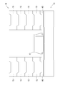
- FIG. 2 is a schematic rear view of the crane truck 10.
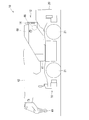
- FIG. 3 is a schematic side view showing the drum camera 68 and the winch 48.
- FIG. 4 is a schematic plan view showing the drum camera 68 and the winch 48.
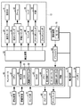
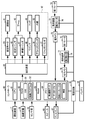
- FIG. 5 is a functional block diagram of the crane vehicle 10 according to the embodiment.
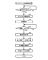
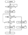
- FIG. 6 is a flowchart showing the counterweight determination process.
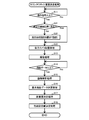
- FIG. 7 is a flowchart showing the boom control processing.
- FIG. 8 is a plan view of the crane vehicle 10 according to the first and second modifications.
- FIG. 9 is a functional block diagram of the crane vehicle 10 according to the first modification.
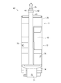
- FIG. 10 is a flowchart illustrating a counterweight weight determination process according to the first modification.
- FIG. 11 is a functional block diagram of the crane vehicle 10 according to the second modification.
- FIG. 12 is a flowchart illustrating a counterweight weight determination process according to the second
- FIG. 1 shows a crane vehicle 10 according to the present embodiment.
- the crane vehicle 10 is an example of the “work vehicle” of the present invention.
- the working vehicle is not limited to the crane vehicle 10.
- the work vehicle may be any as long as it can mount a counter weight 14 described later.
- the crane vehicle 10 mainly includes a traveling body 11, a crane device 12 and a cabin 13 mounted on the traveling body 11.
- the traveling body 11 includes a vehicle body 20, an axle and wheels 21, not shown, an engine, not shown, a battery 24 (FIG. 5), and a hydraulic device 22 (FIG. 5).
- the axle is rotatably supported by the vehicle body 20. Wheels 21 are held at both ends of the axle.
- the engine rotationally drives the axle and rotates the wheels 21 via the axle. Further, the engine charges the battery 24. Furthermore, the engine drives a hydraulic pump (not shown) of the hydraulic device 22.
- the hydraulic pump discharges hydraulic oil at a predetermined pressure, and the swing motor 23, the up-and-down cylinder 46, the telescopic cylinder 47, the outrigger cylinder 36, the jack cylinder 37, the winch 48 shown in FIG. 23, etc.).
- the hydraulic device 22 has an electromagnetic valve (not shown) that controls the pilot pressure of the hydraulic oil.
- the solenoid valve is opened and closed by a drive signal input from a controller 60 (FIG. 5) described later.
- the swing motor 23 and the like are driven by opening and closing the solenoid valve. That is, the drive of the turning motor 23 and the like is controlled by the controller 60.
- the turning motor 23 and the like are hydraulic actuators, but all or a part of the turning motor 23 and the like may be electric actuators.
- the vehicle body 20 includes a front outrigger 31 and a rear outrigger 32 for stabilizing the posture of the vehicle body 20, as shown in FIG.
- the front outrigger 31 is provided at a front part of the vehicle body 20.
- the front outrigger 31 includes an outer cylinder (not shown), a pair of left and right inner cylinders 35 (FIG. 5), an outrigger cylinder 36 (FIG. 5), and a pair of left and right jack cylinders 37.
- the outer cylinder extends along the width direction (left-right direction) of the vehicle body 20.
- the inner cylinder 35 is inserted into the outer cylinder, and can slide in the left-right direction of the vehicle body 20. By sliding, the inner cylinder 35 changes its attitude between a stored state stored in the outer cylinder and an extended state in which the vehicle body 20 extends in the width direction.
- the outrigger cylinder 36 is supplied with hydraulic oil from the hydraulic device 22, expands and contracts, and changes the attitude of the inner cylinder 35 between the retracted state and the extended state.
- the jack cylinders 37 are fixed to the distal ends of the inner cylinders 35, respectively.
- the jack cylinder 37 is supplied with hydraulic oil by the hydraulic device 22, and expands and contracts between a separated position separated from the ground and a ground contact position in contact with the ground or an iron plate or the like laid on the ground.
- the rear outrigger 32 is provided at a rear portion of the vehicle body 20.
- the rear outrigger 32 has the same configuration as the front outrigger 31, and includes an outer cylinder, a pair of left and right inner cylinders 35, an outrigger cylinder 36, and a pair of left and right jack cylinders 37.
- the cabin 13 is mounted on a swivel 41 as shown in FIG.
- the cabin 13 has an operating device 17 (FIG. 5) for operating the crane vehicle 10 and a steering device 18 (FIG. 5) for operating the crane device 12.
- the crane vehicle 10 is a so-called rough terrain crane, and is a work vehicle in which the operation of the crane vehicle 10 and the operation of the crane device 12 are performed in one cabin 13.
- the crane vehicle 10 may be an all-terrain crane or a truck crane having two cabins, a cabin having the driving device 17 and a cabin having the steering device 18.
- the control device 18 has an operation lever and an operation button for operating the crane device 12 and the outriggers 31 and 32.
- the control device 18 outputs an operation signal indicating an operation direction and an operation amount of the operation lever, and an operation signal indicating whether or not the operation button is operated.
- the operation signal output from the control device 18 is input to the controller 60 (FIG. 5).
- the control device 18 also includes a display 67 (FIG. 5) for displaying the operation status and images captured by a drum camera 68 (FIG. 3) described later.
- the display 67 is provided in the cabin 13 at a position where the operator seated on the driver's seat can easily recognize the display.
- the cabin 13 has a control box (not shown).
- the control box houses a control board.
- the control board is mounted with a microcomputer, a resistor, a capacitor, a diode, and various ICs, and forms a controller 60 and a power supply circuit 65 shown in FIG. Further, a speaker 66 for outputting sound is mounted on the control board.
- the controller 60 and the power supply circuit 65 will be described later.
- the crane device 12 includes a swivel table 41 that is rotatably supported by the vehicle body 20, and a boom 42 that is supported by the swivel table 41.
- the boom 42 has a proximal boom 43, one or more intermediate booms 44, and a distal boom 45.
- the proximal boom 43, the intermediate boom 44, and the distal boom 45 are nested, and the boom 42 is extendable.
- the base end boom 43 is supported by the swivel base 41 so as to be able to undulate. That is, the boom 42 is undulating and extendable.
- the crane device 12 corresponds to the “boom device” of the present invention.
- the swivel base 41 includes a support 40 that supports the counterweight 14.
- the support 40 is disposed on the base end side of the boom 42 and is fixed to the swivel 41.
- the support 40 may be a table on which the counterweight 14 is placed, or may be a member for suspending or lifting the counterweight 14.
- the counter weight 14 is composed of a plurality of divided weights 15.
- the plurality of divided weights 15 may have the same shape and the same weight, or may be a plurality of types having different shapes and weights such as thickness.
- each of the divided weights 15 has a rectangular plate shape, and is overlapped in the vertical direction.
- each divided weight 15 has a rectangular parallelepiped shape.
- the counterweight 14 is composed of a left divided weight group and a right divided weight group.
- Each of the left and right divided weight groups is composed of a plurality of divided weights 15 (four in the illustrated example) stacked in the vertical direction.
- the mobile crane 10 shown in FIG. 2 is a mobile crane with different specifications from the mobile crane 10 shown in FIG.
- the arrangement of the divided weights 15 is not limited to the examples shown in FIGS.
- the division weights 15 may be arranged in another arrangement as long as the division weights 15 are securely held.
- the total weight of the counterweight 14 corresponds to the sum of the weights of the divided weights 15 constituting the counterweight 14. That is, the total weight of the counterweights 14 varies depending on the type (weight) of the divided weights to be used and the number of the divided weights 15 to be used.
- the total weight of the counterweight 14 is detected by a drum camera 68 and a controller 60 described later. Details will be described later.
- the crane device 12 further includes a turning motor 23, an up-and-down cylinder 46 that raises and lowers the boom 42, and a telescopic cylinder 47 that expands and contracts the boom 42.
- the turning motor 23 is provided on the vehicle body 20.
- the turning motor 23 is supplied with hydraulic oil from the above-described hydraulic device 22, rotates, and turns the turning table 41 via a known gear.
- the up-and-down cylinder 46 is provided on the swivel 41.
- the telescopic cylinder 47 is provided on the boom 42.
- the up-and-down cylinder 46 and the extendable cylinder 47 are supplied with hydraulic oil from the hydraulic device 22 and extend and contract.
- the extending and retracting cylinder 46 raises and lowers the boom 42.
- the telescopic cylinder 47 that expands and contracts causes the boom 42 to expand and contract.
- a swivel (not shown) is provided between the vehicle body 20 and the swivel 41.
- the hydraulic device 22 provided on the vehicle body 20 supplies hydraulic oil to the up-and-down cylinder 46 and the telescopic cylinder 47 through a swivel.
- the crane device 12 includes a winch 48 and a hook 49 as shown in FIG.
- the winch 48 is supplied with hydraulic oil from the hydraulic device 22 via the swivel, and rotates.
- the rotating winch 48 winds up or pulls out a rope (not shown) connected to the hook 49.
- the hook 49 is suspended from the tip of the tip boom 45 by a rope. The hook 49 moves up and down as the winch 48 rotates.
- the boom 42 also has a drum camera 68 shown in FIGS. 3 and 4, and a holding device 69 (FIG. 5) for holding the drum camera 68.
- the drum camera 68 is arranged at a position where the winch 48 and the counterweight 14 can be imaged (photographed), and is fixed to the base end boom 43. Specifically, the drum camera 68 is disposed obliquely in front of the winch 48 in a state where the boom 42 is lying down.
- the holding device 69 holds the drum camera 68 such that the posture of the drum camera 68 can be changed between a first posture in which the lens (not shown) of the drum camera 68 faces the winch 48 and a second posture in which the lens faces the counterweight 14. .
- the holding device 69 holds the drum camera 68 so as to be rotatable around a rotation axis along the left-right direction. That is, the holding device 69 holds the drum camera 68 so that the elevation angle can be changed.
- the elevation angle of the drum camera 68 in the second posture can be changed so as to face the counterweight 14 regardless of the elevation angle of the boom 42. That is, the drum camera 68 can capture an image of the counterweight 14 irrespective of the elevation angle of the boom 42.
- the holding device 69 may include a restricting portion such as a protruding piece that restricts the drum camera 68 from rotating beyond the first posture and the second posture.
- the holding device 69 includes a motor 70 for rotating the drum camera 68 between the first posture and the second posture, as shown in FIG.
- the motor 70 may be a DC motor or an AC motor such as a servo motor or a stepping motor.
- the motor 70 is supplied with a positive or negative DC voltage from a power supply circuit 65 described later, and is rotationally driven at a direction corresponding to the positive / negative of the DC voltage and a rotation speed according to the voltage value.
- Supply of a DC voltage from the power supply circuit 65 to the motor 70 is controlled by a drive signal output from the controller 60. That is, the controller 60 controls the driving of the motor 70.
- the drum camera 68 captures an image of the winch 48 and the counterweight 14 and generates image data.
- the image data generated by the drum camera 68 is input to a controller 60 described later.
- the drum camera 68 corresponds to the “image data generating device” of the present invention.
- the image data generation device may be a device other than a camera as long as it can generate image data.
- an image data generating apparatus irradiates an imaging target with light, receives scattered light scattered by the imaging target, and generates three-dimensional image data of the imaging target from the irradiated light and the received scattered light. It may be a sensor.
- the three-dimensional laser sensor irradiates each part of the imaging region with a pulse laser to perform scanning, for example, and generates three-dimensional image data of an imaging target in the imaging region.
- the imaging path from the drum camera 68 to the winch 48 and the imaging path from the drum camera 68 to the counterweight 14 are open. That is, the drum camera 68 can take an image of the winch 48 by changing the posture to the first posture, and can take an image of the counterweight 14 by changing the posture to the second posture.
- the posture of the drum camera 68 is changed to the first posture and the second posture by the rotation.
- the attitude of the drum camera 68 may be changed to the first attitude and the second attitude by another method such as sliding.
- a driving source other than the motor 70 such as a hydraulic cylinder or an electric cylinder, may be used for the holding device 69.
- the power supply circuit 65 shown in FIG. 5 is a circuit that generates electric power to be supplied to the display 67, the drum camera 68, and the motor 70.
- the power supply circuit 65 is, for example, a DC-DC converter.
- the power supply circuit 65 converts the DC voltage supplied from the battery 24 into a stable DC voltage having a predetermined voltage value and outputs the DC voltage.
- the power supply circuit 65 converts, for example, a DC voltage such as 12 V or 24 V supplied from the battery 24 into a stable DC voltage such as 3.3 V, 5 V, or 12 V and outputs it.
- the power supply circuit 65 is, for example, a switching regulator having a switching element.
- the controller 60 controls the driving of the display 67, the drum camera 68, and the motor 70 by inputting the driving signal to the switching element of the power supply circuit 65.
- the controller 60 includes a CPU 61 as a central processing unit, a ROM 62, a RAM 63, and a memory 64.
- the ROM 62 stores an OS 51, which is an operation system, and a control program 52.
- the control program 52 is executed by the CPU 61 executing an instruction described in an address.
- the control program 52 is a program that controls the driving of the drum camera 68 and the motor 70 to cause the drum camera 68 to generate image data, and determines the total weight of the counterweight 14 from the generated image data. Details will be described later.
- the RAM 63 is used to execute the control program 52.
- the memory 64 stores data necessary for executing the control program 52. Specifically, the memory 64 stores a plurality of basic image data, a data table, a performance data table, and various thresholds.
- the basic image data stored in the memory 64 is image data obtained by previously imaging the counterweight 14 with the drum camera 68.
- One piece of basic image data indicates a counter weight 14 composed of one combination of the divided weights 15.
- one basic image data is an image obtained by imaging a counter weight 14 composed of one first divided weight 15 and one second divided weight 15 having a different weight from the first divided weight 15.
- Another basic image data is an image obtained by capturing a counter weight 14 composed of two second divided weights 15 and two third divided weights 15 having different weights from the second divided weight 15.
- the plurality of basic image data covers all combinations of the divided weights 15 that can be supported by the support 40 (FIG. 1). That is, the same number of basic image data as the number of combinations of the divided weights 15 that can be supported by the support body 40 is stored in the memory 64 in advance.
- each basic image data is identified by the identification symbol.
- the identification symbol may be a number, a letter, or a combination of a number and a letter.
- the data table stored in the memory 64 stores identification symbols and weight values in association with each other. Specifically, a weight value corresponding to the total weight of the counterweight 14 indicated by the basic image data identified by one identification symbol is stored in the data table in association with the identification symbol.
- the performance data table stored in the memory 64 stores weight values and performance data in association with each other.
- the performance data is data for determining the allowable work radius of the boom 42.
- the performance data includes, for example, the upper limit of the up-and-down angle of the boom 42 according to the overhang position of the outriggers 31 and 32, the size of the load (hereinafter referred to as load) of the load suspended by the hook 49, and the length of the boom 42. And data defining the lower limit.
- the performance data is data that defines the upper limit of the length of the boom 42 according to the overhang positions of the outriggers 31 and 32, the magnitude of the load, and the undulation angle of the boom 42.
- the controller 60 controls the drive of the boom 42 using the performance data. Details will be described later.
- the memory 64 may store the above-described data table and the performance data table separately, or may store them as one data table.
- the threshold value stored in the memory 64 is a value used when determining the total weight of the counterweight 14, and is stored in the memory 64 in advance. Details will be described later.
- the controller 60 is connected to the sensor group 16 shown in FIG. 5 using a cable (not shown).
- the sensor group 16 includes, for example, an up-and-down angle sensor that detects the up-and-down angle of the boom 42, a boom length sensor that detects the length of the boom 42, a load sensor that detects the magnitude of the load, and the turning of the swivel 41. It includes a turning angle sensor for detecting the position, an outrigger sensor for detecting the position of the inner cylinder 35 of the outriggers 31 and 32, and the like.
- the sensor signal output from the sensor group 16 is input to the controller 60.
- the controller 60 includes an operation lever and an operation button included in the driving device 17 and the control device 18, a speaker 66, a display 67, a drum camera 68, a power supply circuit 65, and a solenoid valve included in the hydraulic device 22. They are connected using a cable (not shown).
- the controller 60 receives operation signals from the driving device 17 and the control device 18, inputs a voice signal to the speaker 66, and inputs an image signal to the display 67. Further, the controller 60 inputs a control signal to the drum camera 68 to cause the drum camera 68 to take an image, and receives an input of image data generated by the drum camera 68.
- the controller 60 inputs drive signals to the power supply circuit 65, the motor 70, the solenoid valve, and the like, and controls the drive of the motor 70, the swing motor 23, and the like.
- the controller 60 determines whether or not an operation signal serving as a trigger for starting detection of the total weight of the counterweight 14 has been input (S11).
- the operation signal may be input to the controller 60 in response to, for example, a specific operation button for starting detection of the total weight of the counterweight 14 being operated by an operator.
- the operation signal may be input to the controller 60 in response to an operation of an operation lever or an operation button for operating the crane device 12 by an operator. That is, the counterweight determination processing is executed before the operation of the crane device 12 is started.
- the controller 60 waits until an operation signal is input (S11: No). If the controller 60 determines that an operation signal has been input (S11: Yes), the controller 60 executes a drum camera adjustment process (S12).
- the drum camera adjustment process is a process of changing the posture of the drum camera 68 from the first posture to the second posture. More specifically, the controller 60 outputs a drive signal to the power supply circuit 65 to drive the motor 70. The driven motor 70 changes the attitude of the drum camera 68 from the first attitude to the second attitude.
- the drum camera adjustment processing may be omitted.
- the controller 60 may input a control signal for changing the focal length of the drum camera 68 to the drum camera 68.
- the drum camera 68 to which the control signal has been input changes the focal length from the distance to the winch 48 to the distance to the counterweight 14.
- the drum camera 68 may have an autofocus function.
- the controller 60 executes the imaging processing (S13). Specifically, the controller 60 inputs a control signal to the drum camera 68 and causes the drum camera 68 to image the counterweight 14. The drum camera 68 that has imaged the counterweight 14 generates and outputs image data.
- the controller 60 waits until image data is input from the drum camera 68 (S14: No). When image data is input from the drum camera 68 (S14: Yes), the controller 60 executes an image analysis process (S15).
- the controller 60 extracts, from the input image data, a singular point at which the color, lightness, and luminance change by a threshold or more.
- the threshold is stored in the memory 64 in advance.
- the controller 60 temporarily stores the extracted data indicating the distribution of the singular points (hereinafter, also referred to as detection data) in the memory 64, and ends the image analysis processing.
- the controller 60 executes binarization processing on the image data input from the drum camera 68 and then extracts a singular point. You may.
- the basic image data determination process is a process of selecting and determining the image data that matches the image data input from the drum camera 68 from among a plurality of basic image data stored in the memory 64.
- the controller 60 selects one piece of basic image data from a plurality of pieces of basic image data, executes the above-described image analysis processing on the selected piece of basic image data, and outputs data indicating the distribution of singular points ( Hereinafter, also referred to as basic data). Then, the controller 60 calculates the coincidence rate between the acquired basic data and the above-described detection data, and stores the calculated coincidence rate in the memory 64 in association with the identification symbol of the basic image data. The controller 60 performs an image analysis process on all the basic image data, and stores the matching rate calculated in association with the identification symbol in the memory 64. Then, the controller 60 determines the basic image data indicated by the identification symbol associated with the highest matching rate as the basic image data that matches the image data input from the drum camera 68.
- the controller 60 may determine the basic image data whose calculated coincidence rate is equal to or larger than the threshold value stored in the memory 64 in advance as the basic image data that matches the image data input from the drum camera 68. In that case, it is not necessary to calculate the coincidence rate for all the basic image data. As a result, the processing load on the CPU 61 is reduced, and the processing speed of the controller 60 is increased.
- a plurality of basic data indicating a distribution of a singular point may be stored in the memory 64 in advance, instead of or together with the plurality of basic image data.
- the basic data corresponds to “basic image data” of the present invention.
- the basic image data that matches image data input from the drum camera 68 may be determined from a plurality of basic image data by another method. That is, any image analysis method may be selected as long as basic image data that matches the image data input from the drum camera 68 can be determined from among a plurality of basic image data.
- the controller 60 executes a total weight determination process of determining the total weight of the counterweight 14 captured by the drum camera 68 (S17). Specifically, the controller 60 selects and determines a weight value associated with the identification symbol of the basic image data determined in the basic image data determination processing from the data table stored in the memory 64. The controller 60 determines the weight value selected and determined from the data table as the total weight of the counterweight 14 captured by the drum camera 68.
- the controller 60 executes a performance data determination process (S18). Specifically, the controller 60 selects and determines performance data corresponding to the weight value determined in step S17 from the performance data table stored in the memory 64.
- the performance data table may store the weight value and the correction value in association with each other. In that case, the controller 60 selects and determines a correction value corresponding to the weight value determined in step S17. The controller 60 corrects the predetermined performance data using the determined correction value.
- the controller 60 ends the counterweight determination process in response to the determination of the performance data. Then, the controller 60 executes the boom control processing shown in FIG. 7 using the determined performance data.
- the controller 60 changes the direction of the lens of the drum camera 68 facing the counterweight 14 to the winch 48. Change to the facing direction. Specifically, the controller 60 drives the motor 70 in the opposite direction to the drum camera adjustment processing, and changes the attitude of the drum camera 68 in the second attitude to the first attitude.
- the controller 60 waits until an operation signal for operating the boom 42 is input from the control device 18 (S21: No). That is, the boom control process is executed with the input of the operation signal as a trigger.
- the controller 60 determines that the operation signal has been input (S21: Yes)
- the controller 60 starts the operation of the boom 42 based on the input operation signal (S22). Specifically, the controller 60 inputs a drive signal to an electromagnetic valve or the like of the hydraulic device 22 to drive the swing motor 23, the up / down cylinder 46, and the telescopic cylinder 47.
- the controller 60 turns the turning position of the turning table 41, the up / down angle of the boom 42, and the boom 42.
- the extension length of is detected.
- the controller 60 determines whether or not the up-and-down angle and the extension length of the boom 42 at the detected turning position have reached values determined by the performance data determined in the counterweight determination process (S23). That is, in step S23, it is determined whether the boom 42 has reached the end of the allowable working radius.
- the controller 60 determines whether the input of the operation signal has stopped (S24). ). When determining that the input of the operation signal has stopped (S24: Yes), the controller 60 normally stops the boom 42 (S25), and ends the boom control processing.
- the normal stop means stopping the boom 42 due to the stop of the input of the operation signal. In this case, when the operation signal is input again, the controller 60 executes the boom control process again.
- step S24 determines in step S24 that the operation signal has been continuously input (S24: No)
- the controller 60 executes the process of step S23 again. That is, while the boom 42 is being operated by the input operation signal, the controller 60 determines whether or not the up-and-down angle and the extension length of the boom 42 have reached values determined by the performance data determined in the counterweight determination processing. Is determined continuously (S23).
- step S23 When the controller 60 determines in step S23 that the up-and-down angle and the extension length of the boom 42 have reached the values determined by the performance data determined in the counterweight determination process (S23: Yes), the controller 60 informs the stop of the boom 42. (S26). Specifically, the controller 60 displays a warning screen on the display 67 or causes the speaker 66 to output a warning sound. Thereafter, the controller 60 forcibly stops the boom 42 (S27), and ends the boom control processing.
- the forced stop means stopping the boom 42 irrespective of whether an operation signal is input. In this case, the controller 60 does not execute the boom control process even if an operation signal is input until, for example, a switch (not shown) for canceling the forced stop is operated.
- the controller 60 causes the drum camera 68 facing the winch 48 to capture an image of the winch 48 in response to input of an operation signal for operating the boom 42 and the winch 48. .
- the drum camera 68 captures an image of the winch 48 to generate image data (video data), and inputs the generated image data to the controller 60.
- the controller 60 inputs the input image data to the display 67, and displays an image of the winch 48 on the display 67.
- the controller 60 While the controller 60 is operating the boom 42, that is, while executing the boom control process shown in FIG. May be periodically executed. For example, the controller 60 operates the countdown timer counter after executing the counterweight determination processing, and executes the counterweight determination processing again when determining that the countdown timer counter becomes zero. Therefore, the safety of the crane vehicle 10 is further enhanced.
- the controller 60 determines the total weight of the counterweight 14 supported by the support 40 based on the image data generated by the drum camera 68. Therefore, the crane vehicle 10 of the present embodiment can detect the total weight of the counterweight 14 with a simple configuration, regardless of the type and number of the divided weights 15 constituting the counterweight 14.
- Image data obtained by capturing the counterweight 14 is generated by using a drum camera 68 that captures an image of the winch 48. Therefore, it is not necessary to newly provide a camera in order to obtain image data obtained by imaging the counterweight 14. As a result, the crane vehicle 10 of the present embodiment can reduce the number of parts, the manufacturing cost, and the number of manufacturing steps.
- the drum camera 68 since the drum camera 68 is provided on the boom 42, it rotates with the counterweight 14. Therefore, the drum camera 68 can image the counterweight 14 and generate image data regardless of the turning position of the turning table 41.
- the crane vehicle 10 of the above-described embodiment uses the drum camera 68 to image the counterweight 14.
- the mobile crane 10 ′ of the present modified example captures an image of the counterweight 14 using a rear camera 71 that captures an image of the rear of the mobile crane 10 ′.
- the details will be described below. Note that the same configurations and processes as those of the above-described embodiment are denoted by the same reference numerals as those of the embodiment, and description thereof will be omitted.
- the rear camera 71 is installed on the upper surface of the rear part of the vehicle body 20.
- the rear camera 71 is moved by the holding device 72 shown in FIG. 9 into a third posture in which the lens of the rear camera 71 faces the rear of the vehicle body 20 and a fourth posture in which the lens of the rear camera 71 faces the front counterweight 14. It is held so that the posture can be changed.
- FIG. 8 shows a state in which the rear camera 71 is in the fourth posture facing the front counterweight 14.
- the holding device 72 is held by the vehicle body 20 so as to be rotatable around a first rotation axis along the vertical direction.
- the holding device 72 holds the rear camera 71 so as to be rotatable around a second rotation axis along the horizontal direction.
- the holding device 72 is rotated between a third posture in which the lens of the rear camera 71 faces backward of the vehicle body 20 and a fourth posture in which the lens faces forward.
- the holding device 72 is rotated around the first rotation axis by the first motor 73 shown in FIG.
- the first motor 73 is provided on the vehicle body 20.
- the holding device 72 includes a second motor 74.
- the second motor 74 rotates the rear camera 71 around the second rotation axis. That is, the second motor 74 changes the elevation angle of the rear camera 71.
- the first motor 73 and the second motor 74 are DC motors or AC motors, similarly to the motor 70 described in the embodiment.
- the first motor 73 and the second motor 74 are DC motors will be described.
- the first motor 73 and the second motor 74 are driven by being supplied with a DC voltage from the power supply circuit 65.
- the supply of the DC voltage from the power supply circuit 65 to the first motor 73 and the second motor 74 is controlled by a drive signal input from the controller 60 to the power supply circuit 65. That is, the direction and the number of rotations of the first motor 73 and the second motor 74 are controlled by the controller 60.
- the holding device 72 may have a restricting portion that restricts the rear camera 71 from rotating more than necessary.
- the vehicle body 20 may include a restriction unit that restricts the rear camera 71 from rotating beyond the third posture and the fourth posture.
- the counterweight determination process executed by the controller 60 according to the present modification will be described with reference to FIG.
- the controller 60 determines whether or not the swivel table 41 is at a predetermined turning position, as in the above-described embodiment (S31).
- the predetermined turning position is, for example, a position where the tip of the boom 42 that has fallen faces forward of the vehicle body 20. That is, the controller 60 turns the turntable 41 to the turning position where the rear camera 71 faces the counterweight 14.
- the rear camera 71 and the counterweight 14 need not necessarily face each other as long as the rear camera 71 can image the entire counterweight 14.
- the position at which the rear camera 71 obliquely images the counterweight 14 may be a predetermined turning position so that the rear camera 71 can image the entire counterweight 14.
- the controller 60 determines that the swivel table 41 is at the predetermined turning position (S31: Yes). If the controller 60 determines that the turntable 41 is not at the predetermined turning position (S31: No), the controller 60 turns the turntable 41 to the predetermined turning position (S32).
- the predetermined turning position is stored in the memory 64 in advance. The controller 60 stops turning of the swivel base 41 in response to the turning position detected by the swivel angle sensor of the sensor group 16 reaching the swivel position stored in the memory 64 in advance, and moves the swivel base 41 to a predetermined swivel position. Position.
- the controller 60 executes a rear camera adjustment process of changing the direction of the lens of the rear camera 71 from rear to front (S33). Specifically, the controller 60 inputs a drive signal to the power supply circuit 65 and drives the first motor 73. The driven first motor 73 rotates the holding device 72 until the lens of the rear camera 71 faces forward. Next, the controller 60 inputs a drive signal to the power supply circuit 65 to drive the second motor 74. The driven second motor 74 rotates the rear camera 71 to a fourth position in which the lens of the rear camera 71 faces obliquely forward and upward. When the initial posture of the rear camera 71 is the fourth posture, the rear camera adjustment processing may be omitted.
- the controller 60 executes the processing from step S13 to step S18 as in the embodiment, determines the total weight of the counterweight 14, determines the performance data from the determined total weight of the counterweight 14, and determines the counter data. The weight determination process ends. Then, the controller 60 executes the boom control processing shown in FIG. 7 using the determined performance data.
- a crane vehicle 10 ′ according to this modification captures an image of the counterweight 14 using the existing rear camera 71. Therefore, it is not necessary to newly provide a camera in order to obtain image data obtained by imaging the counterweight 14. As a result, the crane vehicle 10 'of this modification can reduce the number of parts, the manufacturing cost, and the number of manufacturing steps.
- the crane vehicle 10 of the above-described embodiment uses the drum camera 68 to image the counterweight 14.
- the crane truck 10 ′ (FIG. 8) of the present modified example captures an image of the counterweight 14 using the left camera 75 and the right camera 76 that capture the side of the vehicle body 20.
- This modification is particularly useful when, for example, as shown in FIG. 2, the counterweight 14 is composed of a left divided weight group and a right divided weight group. Note that the same configurations and processes as those of the above-described embodiment are denoted by the same reference numerals as those of the embodiment, and description thereof will be omitted.
- the left camera 75 is installed on the upper part of the left side of the vehicle body 20 and at the center in the front-rear direction of the vehicle body 20, as shown in FIG.
- the right camera 76 is installed on the right side of the vehicle body 20 and on the upper surface of the central part in the front-rear direction of the vehicle body 20.
- the left and right cameras 75 and 76 are respectively held by the holding device 77 shown in FIG.
- the configuration of the holding device 77 is almost the same as the holding device 72 described in the first modification.
- One holding device 77 has a posture in which the lens of the left camera 75 faces the left of the vehicle body 20 (shown by a broken line in FIG. 8) and a posture in which the lens (not shown) of the left camera 75 faces the counterweight 14 at the rear (see FIG. 8, the left camera 75 is held so that the posture can be changed.
- the other holding device 77 has a posture in which the lens of the right camera 76 faces the right of the vehicle body 20 (indicated by a broken line in FIG. 8) and a posture in which the lens of the right camera 76 faces the rear counterweight 14 (indicated by a solid line in FIG. 8).
- the right camera 76 is held so that the posture can be changed.
- the counterweight determination process executed by the controller 60 according to the present modification will be described with reference to FIG.
- the controller 60 determines whether or not the swivel table 41 is at the predetermined first turning position, as in the above-described embodiment (S41).
- the predetermined first turning position is a position where the rearwardly facing left camera 75 can capture an image of the left side of the counterweight 14 (the left divided weight group).
- the predetermined first turning position is stored in the memory 64 in advance.
- the controller 60 determines that the turntable 41 is at the predetermined first turn position (S41: Yes)
- the controller 60 skips the process of step S42. If the controller 60 determines that the turntable 41 is not at the predetermined first turning position (S41: No), the controller 60 turns the turntable 41 to the predetermined first turning position in the same manner as in the above-described first modification (S42). ).
- the controller 60 After turning the swivel 41 to the predetermined first turning position, the controller 60 executes a left camera adjustment process for changing the direction of the lens of the left camera 75 from left to rear (S43). Specifically, the controller 60 drives the motors 73 and 74 in the same manner as in the first modification to change the direction and the elevation angle of the left camera 75.
- the controller 60 executes a left camera imaging process for causing the left camera 75 to image the counterweight 14 (S44). Then, the controller 60 waits until image data (hereinafter, also referred to as left image data) generated by the left camera 75 imaging the counterweight 14 is input (S45: No). When the controller 60 determines that the left image data has been input (S45: Yes), the controller 60 stores the input left image data in the memory 64, and then determines whether or not the swivel base 41 is at the predetermined second turning position. A determination is made (S51).
- image data hereinafter, also referred to as left image data
- the predetermined second turning position is a position where the right camera 76 facing backward can capture an image of the right side of the counter weight 14 (the right divided weight group).
- the predetermined second turning position is stored in the memory 64 in advance.
- the controller 60 determines that the turntable 41 is at the predetermined second turn position (S51: Yes)
- the controller 60 skips the process of step S52.
- the controller 60 determines that the turntable 41 is not at the predetermined second turning position (S51: No)
- the controller 60 turns the turntable 41 to the predetermined second turning position in the same manner as in the first modification (S52). ).
- the first turning position and the second turning position described above may be the same position or may be different.
- the controller 60 After turning the swivel 41 to the predetermined second turning position, the controller 60 executes a right camera adjustment process for changing the direction of the lens of the right camera 76 from right to backward (S53). Specifically, the controller 60 drives the motors 73 and 74 to change the direction of the right camera 76 as in the first modification.
- the controller 60 executes a right camera imaging process for causing the right camera 76 to image the counterweight 14 (S54). Then, the controller 60 waits until image data (hereinafter, also referred to as right image data) generated by the right camera 76 capturing the counterweight 14 is input (S55: No). When the controller 60 determines that the right image data has been input (S55: Yes), the controller 60 stores the input right image data in the memory 64, and then executes the processing of steps S15 to S18 as in the above-described embodiment. I do.
- image data hereinafter, also referred to as right image data
- the controller 60 determines the total weight of the left divided weight group based on the left image data, determines the total weight of the right divided weight group based on the right image data, and determines the determined left and right divided weights. The sum of the total weight of the group is determined as the total weight of the counterweight 14. Then, the controller 60 determines the performance data based on the determined total weight of the counterweight 14, and executes the boom control process shown in FIG. 7 using the determined performance data.
- the left image data and the right image data correspond to “first image data” and “second image data” of the present invention.
- the memory 64 stores in advance a plurality of left basic image data obtained by the left camera 75 taking an image of the left side (a group of left divided weights) of the counter weight 14 at the first turning position.
- the memory 64 also stores in advance a plurality of right basic image data obtained by the right camera 76 taking an image of the right side of the counter weight 14 (the right divided weight group) at the second turning position.
- the left basic image data and the right basic image data cover all combinations of the divided weights 15.
- the left camera 75 captures an image of the left side of the counterweight 14, and the right camera 76 captures an image of the right side of the counterweight 14. Therefore, as shown in FIG. 2, a crane truck in which it is difficult to image the entire counterweight 14 with a single camera, such as when the counterweight 14 is composed of a left divided weight group and a right divided weight group. Even if it is 10 ', the crane vehicle 10' can image the counterweight 14 and determine the total weight of the counterweight 14.
- the mobile crane 10 ′ captures an image of the counterweight 14 using the existing left and right cameras 75 and 76. Therefore, it is not necessary to newly provide a camera in order to obtain image data obtained by imaging the counterweight 14. As a result, the crane vehicle 10 'of this modification can reduce the number of parts, the manufacturing cost, and the number of manufacturing steps.
- the total weight of the counterweight 14 is determined based on the image data generated by the drum camera 68 and the plurality of basic image data stored in the memory 64 has been described in the above embodiment.
- the total weight of the counterweight 14 may be determined based only on the image data generated by the drum camera 68.
- the controller 60 extracts a singular point based on the image data generated by the drum camera 68, determines the outer shape (outline) of the counterweight 14 from the extracted singular point, and calculates the area surrounded by the determined outer shape. decide.
- the memory 64 stores a data table in which the area and the weight value are associated with each other. The controller 60 selects a weight value corresponding to the determined area, and determines the selected weight value as the total weight of the counterweight 14.
- the memory 64 stores a data table in which a plurality of outline images indicating the outline of the counterweight 14, the identification symbols assigned to the outline images, and the weight values are associated.
- the controller 60 selects and determines, from the plurality of outline images stored in the memory 64, an outline image whose matching rate with the determined outline of the counterweight 14 is equal to or greater than the threshold value stored in the memory 64. Then, the controller 60 selects and determines the weight value associated with the identification symbol given to the determined outer shape image from the data table. The controller 60 determines the determined weight value as the total weight of the counterweight. As described above, any method may be used as long as the weight value can be determined based on the image data generated by the drum camera 68.
- the drum camera 68, the rear camera 71, and the left and right cameras 75 and 76 generate image data has been described in the above embodiment and the first and second modifications. That is, an example has been described in which image data is generated by imaging the counterweight 14 using an existing camera.
- a dedicated camera for imaging the counterweight 14 or a three-dimensional laser sensor may be provided in the crane vehicles 10 and 10 '.
- the dedicated camera and the three-dimensional laser sensor may be provided on the vehicle body 20, may be provided on the swivel base 41, or may be provided on the boom 42.
- the counter weight 14 may be imaged using an existing camera other than the drum camera 68, the rear camera 71, and the left and right cameras 75 and 76, and image data may be generated.
- the camera and the three-dimensional laser sensor may not be provided in the crane trucks 10 and 10 '.
- a mobile terminal including a camera and a communication module may be used.
- the operator images the counterweight 14 from a predetermined angle of view and distance using a portable terminal.
- the mobile terminal transmits image data generated by imaging the counterweight 14 using the communication module.
- the controller 60 includes a communication module.
- the controller 60 receives the image data transmitted by the mobile terminal directly or via a communication base station or the like.
- the controller 60 determines the total weight of the counterweight 14 using the received image data.
- the predetermined distance is, for example, a distance of about 2 to 8 m away from the counterweight 14.
- the predetermined angle of view is, for example, an angle of view when imaging the counterweight 14 from a height position of 1 m from the ground.
- the crane device 12 has been described in the above embodiment as an example of the “boom device” of the present invention.
- the “boom device” of the present invention may be a gripping device provided with a gripping mechanism at the tip of the boom 42 in addition to the crane device 12, or may be another device.
- the controller 60 is configured by the CPU 61, the ROM 62 that stores the control program 52, and the like has been described in the above embodiment.
- the controller 60 may be configured as a so-called analog circuit that does not use a microcomputer, such as an IC such as an operational amplifier, a resistor, and a capacitor.
- the example in which the basic image data, the data table, and the performance data table are stored in the memory 64 has been described in the above embodiment.
- a mounting section for mounting a portable storage medium such as a USB memory or an SD card storing the basic image data, the data table, and the performance data table may be provided on the control board or the like.
- the portable storage medium is replaced in accordance with the addition of the type of the division weight 15. Therefore, it is possible to cope with the addition of the types of the divided weights 15 without replacing the control board forming the controller 60.
- the portable storage medium corresponds to the “memory” of the present invention.
- drum camera 68 is provided on the base end boom 43 has been described in the above embodiment.
- the drum camera 68 may be provided on the swivel 41 according to the mounting position of the winch 48.
- drum camera 68, the rear camera 71, and the left and right cameras 75, 76 are moved by the motors 70, 73, 74 have been described in the above-described embodiments and the modifications.
- the drum camera 68, the rear camera 71, and the left and right cameras 75 and 76 may be manually moved by an operator.
- the drum camera 68, the rear camera 71, and the left and right cameras 75 and 76 may be connected to the controller 60 by a cable or the like, or may be wirelessly connected to the controller 60.
- the drum camera 68, the rear camera 71, and the left and right cameras 75 and 76 include batteries such as rechargeable batteries.
Landscapes
- Engineering & Computer Science (AREA)
- Mechanical Engineering (AREA)
- Jib Cranes (AREA)
Abstract
【課題】分割ウエイトの種類に拘わらず簡単な構成でカウンタウエイトの重量を検出可能な作業車を提供する。 【解決手段】クレーン車のブーム42は、ウインチ48と、ウインチ48及びカウンタウエイトを撮像するドラムカメラ68とを有する。ドラムカメラ68がカウンタウエイトを撮像することによって生成した画像データは、コントローラ60に入力される。コントローラ60は、入力された画像データに基づいて、メモリ64が予め記憶する複数の基本画像データの中から一の基本画像データを選択して決定する。コントローラ60は、決定した基本画像データと対応する重量値を、カウンタウエイト14の総重量に決定する。コントローラ60は、決定したカウンタウエイト14の総重量に対応する性能データを決定し、決定した性能データを用いてブーム制御処理を実行する。
Description
この発明は、カウンタウエイトを搭載可能な作業車に関する。
カウンタウエイトを搭載可能な作業車がある。作業車は、クレーン車などである。作業車は、カウントウエイトを搭載することにより、安全に作業を行う。
カウンタウエイトは、吊下する荷の重量に応じて作業車に搭載される。具体的には、複数個の分割ウエイトが準備され、クレーン車が吊下する荷の重量に適した総重量となる分割ウエイトの個数が決定され、決定された個数の分割ウエイトが作業車に搭載される。
カウンタウエイトの重量は、例えば、クレーン車のブームの起伏角度や伸長長さの限界値(性能データ)を決定するために、検出されることが望ましい。
特許文献1は、カウンタウエイトの重量を検出する重量検出装置が搭載されたクレーン車を開示する。
特許文献2は、分割ウエイトに接続コネクタが設けられ、当該接続コネクタと接続される接続コネクタを有する検出装置が旋回台に配置されたクレーン車を開示する。検出装置は、相互に接続された2つの接続コネクタを通じて形成された回路を用いて、分割ウエイトの個数を検出し、検出した分割ウエイトの個数からカウンタウエイトの重量を算出する。
特許文献1に記載の重量検出装置は、カウンタウエイトの重量を直接検出するので、装置として大型である。
特許文献2に記載の検出装置は、各分割ウエイトにそれぞれ接続コネクタを設けなければならないという問題を有する。また、特許文献2に記載の検出装置は、オペレータによる接続コネクタの接続ミスが生じ得るという問題も有する。また、特許文献2に記載の検出装置は、検出装置に設けられる接続コネクタの数によって、検出可能な分割ウエイトの個数が限定されるという問題も有する。また、特許文献2に記載の検出装置は、複数個の分割ウエイトが同一の重量であることを前提にして、分割ウエイトの個数を検出して分割ウエイトの総重量を算出する。したがって、特許文献2に記載の検出装置は、種々の重量の分割ウエイトを用いてカウンタウエイトを構成することができないという問題も有する。すなわち、作業車のユーザが希望する分割ウエイトの組み合わせで当該ユーザに作業車を提供することは、引用文献2に記載の検出装置では困難である。
本発明は、上記の事情に鑑みてなされたものであり、分割ウエイトの種類に拘わらず、カウンタウエイトの重量を簡単な構成で検出可能な手段を提供することを目的とする。
(1) 本発明に係る作業車は、車体と、上記車体に搭載されており、旋回、起伏、及び伸縮可能なブーム装置と、上記ブーム装置に設けられており、複数の分割ウエイトからなるカウンタウエイトを支持可能な支持体と、上記支持体に支持された上記カウンタウエイトを検出して画像データを出力する画像データ生成装置と、上記画像データ生成装置から入力された画像データに基づいて、上記支持体に支持された上記カウンタウエイトの総重量を決定するコントローラと、を備える。
画像データ生成装置は、撮像素子を有するカメラや、レーザ光を照射し、カウンタウエイトで散乱された散乱光を検出して画像データを生成する3次元レーザセンサなどである。コントローラは、画像データ生成装置が生成した画像データに基づいて、支持体に支持されたカウンタウエイトの総重量を決定する。すなわち、カウンタウエイトの総重量が、画像データ生成装置及びコントローラによって検出される。したがって、本発明に係る作業車は、カウンタウエイトを構成する分割ウエイトが複数種類であっても、カウンタウエイトの総重量を簡単な構成で検出することができる。
(2) 上記コントローラは、複数の基本画像データ及び当該各基本画像データにそれぞれ対応付けられた重量値を記憶するメモリから、当該基本画像データ及び重量値を取得し、上記画像データ生成装置から入力された画像データに基づいて一の上記基本画像データを決定し、決定した上記基本画像データに対応付けられた重量値を、上記支持体に支持された上記カウンタウエイトの総重量として決定してもよい。
コントローラは、例えば、画像データ生成装置が生成した画像データから、色や明度や輝度が閾値を超えて変化する特異点を抽出する。そして、コントローラは、抽出した特異点の分布に一番近い分布を有する基本画像データを、メモリから取得した複数の基本画像データの中から決定し、決定した基本画像データに対応付けられた重量値を、カウンタウエイトの総重量として決定する。
(3) 上記ブーム装置は、ロープを繰り出し及び巻き取るウインチを有しており、上記画像データ生成装置は、上記ブーム装置に設けられており、上記ウインチを向く第1姿勢と、上記支持体に支持された上記カウンタウエイトを向く第2姿勢とに姿勢変化してもよい。
画像データ生成装置は、ウインチを向く第1姿勢においてウインチを検出し、カウンタウエイトを向く第2姿勢においてカウンタウエイトを検出する。画像データ生成装置は、オペレータによって第1姿勢や第2姿勢にされてもよいし、モータなどの駆動源によって第1姿勢や第2姿勢にされてもよい。画像データ生成装置は、コントローラがカウンタウエイトの総重量を検出する際に第2姿勢にされ、ウインチを使用する作業時において第1姿勢にされる。したがって、本発明に係る作業車は、ウインチを検出する画像データ生成装置を利用して、カウンタウエイトの総重量の検出を行うことができる。また、画像データ生成装置は、ブーム装置に設けられているので、支持体に支持されたカウンタウエイトとともに旋回する。したがって、ブーム装置の旋回位置に拘わらず、カウンタウエイトを検出することができる。
(4) 上記画像データ生成装置は、上記車体に設置されており、上記コントローラは、上記ブーム装置が上記車体に対して所定の旋回位置にあるか否かを判断し、上記ブーム装置が当該所定の旋回位置にあることに応じて、上記支持体に支持された上記カウンタウエイトを上記画像データ生成装置に検出させて上記画像データを取得してもよい。
コントローラは、ブーム装置が所定の旋回位置にあることに応じて、カウンタウエイトを画像データ生成装置に検出させて画像データを取得する。したがって、コントローラは、基本画像データと同じ画角でカウンタウエイトを検出した画像データと基本画像データとを対比することができる。その結果、取得した画像データと基本画像データとが一致するか否かの判断が正確になる。また、カウンタウエイトの総重量の検出精度が高くなる。
(5) 上記画像データ生成装置は、上記車体の幅方向における両側にそれぞれ設置されていてもよい。上記コントローラは、上記ブーム装置が上記車体に対して所定の第1旋回位置にあるか否かを判断し、上記ブーム装置が当該第1旋回位置にあることに応じて、上記画像データ生成装置のうちのいずれか一方に、上記支持体に支持された上記カウンタウエイトを検出させて第1画像データを取得し、上記ブーム装置が上記車体に対して所定の第2旋回位置にあるか否かを判断し、上記ブーム装置が当該第2旋回位置にあることに応じて、上記画像データ生成装置のうちのいずれか他方に、上記支持体に支持された上記カウンタウエイトを検出させて第2画像データを取得する。
作業車の種類や、分割ウエイトが幅方向において並列して支持体に支持されるなど、カウンタウエイトの種類によっては、カウンタウエイトの全体を1つの画像データ生成装置で検出することが困難な場合がある。画像データ生成装置は、車体の幅方向における両側にそれぞれ設置される。一方の画像データ生成装置は、カウンタウエイトの一方の側を検出する。他方の画像データ生成装置は、カウンタウエイトの他方の側を検出する。すなわち、2台の画像データ生成装置は、幅方向におけるカウンタウエイトの両側をそれぞれ検出する。第1旋回位置と第2旋回位置とは、同じ位置であってもよいし、違っていてもよい。本発明に係る作業車は、2台の画像データ生成装置でカウンタウエイトの両側を検出するので、1台の画像データ生成装置によってカウンタウエイトの全体の検出が困難な場合であっても、カウンタウエイトの総重量の検出を行うことができる。
(6) 上記コントローラは、上記重量値に対応する上記ブーム装置の起伏角及び伸縮長さの範囲である性能データを記憶するメモリから上記重量値及び上記性能データを取得し、上記ブーム装置の起伏角及び伸縮長さが、上記総重量と同一の上記重量値に対応する上記性能データの範囲を超えているか否かを判断し、超えていると判断したことに応じて、上記ブーム装置の駆動を停止させてもよい。
コントローラは、取得した画像データから決定したカウンタウエイトの総重量と同一の重量値に対応する性能データを特定し、ブーム装置の起伏角及び伸縮長さが、特定した性能データの範囲を超えていると判断したことに応じて、ブーム装置の駆動を停止させる。すなわち、ブーム装置は、支持体に支持されたカウンタウエイトの総重量に応じて駆動及び停止される。その結果、作業車の安全性がさらに高められる。
(7) 上記コントローラは、上記ブーム装置を駆動させていることに応じて、所定の時間間隔で上記性能データを決定してもよい。
コントローラは、ブーム装置を駆動させていることに応じて、所定の時間間隔で性能データを決定する。すなわち、コントローラは、支持体に支持されたカウンタウエイトの装着状態を定期的に確認する。したがって、作業車の安全性がさらに高められる。
本発明に係る作業車は、分割ウエイトの種類に拘わらず、カウンタウエイトの総重量を簡単な構成で検出することができる。
以下、本発明の好ましい実施形態が、適宜図面が参照されつつ説明される。なお、本実施形態は、本発明の一態様にすぎず、本発明の要旨を変更しない範囲で実施態様が変更されてもよいことは、言うまでもない。
図1は、本実施形態に係るクレーン車10を示す。クレーン車10は、本発明の「作業車」の一例である。ただし、作業車は、クレーン車10に限られない。作業車は、後述のカウンタウエイト14を搭載可能なものであればよい。
クレーン車10は、走行体11と、走行体11に搭載されたクレーン装置12及びキャビン13と、を主に備える。
走行体11は、車体20と、不図示の車軸及び車輪21と、不図示のエンジンと、バッテリ24(図5)と、油圧装置22(図5)と、を備える。
車軸は、車体20に回転可能に支持されている。車輪21は、車軸の両端に保持されている。エンジンは、車軸を回転駆動し、車軸を介して車輪21を回転させる。また、エンジンは、バッテリ24を充電する。さらにまた、エンジンは、油圧装置22が備える不図示の油圧ポンプを駆動させる。油圧ポンプは、所定圧力の作動油を吐出し、図5が示す旋回モータ23、起伏シリンダ46、伸縮シリンダ47、アウトリガシリンダ36、ジャッキシリンダ37、及びウインチ48や、その他のアクチュエータ(以下、旋回モータ23等とも記載する)を駆動する。油圧装置22は、作動油のパイロット圧を制御する不図示の電磁弁を有する。電磁弁は、後述のコントローラ60(図5)から入力される駆動信号によって開閉される。電磁弁が開閉されることにより、旋回モータ23等が駆動される。すなわち、旋回モータ23等は、コントローラ60によって駆動を制御される。なお、本実施形態では、旋回モータ23等が油圧アクチュエータである例が説明されるが、旋回モータ23等の全部或いは一部は、電動アクチュエータであってもよい。
車体20は、図1が示すように、車体20の姿勢を安定させる前アウトリガ31及び後アウトリガ32を備える。
前アウトリガ31は、車体20の前部に設けられている。前アウトリガ31は、不図示の外筒と、左右一対の内筒35(図5)と、アウトリガシリンダ36(図5)と、左右一対のジャッキシリンダ37とを備える。
外筒は、車体20の幅方向(左右方向)に沿って延びている。内筒35は、外筒に内挿されており、車体20の左右方向にスライド可能である。内筒35は、スライドすることにより、外筒に格納された格納状態と、車体20の幅方向に張り出した張出状態とに姿勢変化する。アウトリガシリンダ36は、油圧装置22から作動油を供給されて伸縮し、内筒35を格納状態と張出状態との間で姿勢変化させる。ジャッキシリンダ37は、各内筒35の先端にそれぞれ固定されている。ジャッキシリンダ37は、油圧装置22によって作動油を供給され、地面から離間する離間位置と、地面または地面に敷設された鉄板等に当接する接地位置との間で伸縮する。
後アウトリガ32は、車体20の後部に設けられている。後アウトリガ32は、前アウトリガ31と同様の構成であり、外筒、左右一対の内筒35、アウトリガシリンダ36、及び左右一対のジャッキシリンダ37を備える。
キャビン13は、図1が示すように、旋回台41に搭載されている。キャビン13は、クレーン車10の運転を行う運転装置17(図5)と、クレーン装置12の操縦を行う操縦装置18(図5)と、を有する。すなわち、クレーン車10は、いわゆるラフテレーンクレーンであって、クレーン車10の運転及びクレーン装置12の操縦が1つのキャビン13で行われる作業車である。但し、クレーン車10は、運転装置17を有するキャビンと、操縦装置18を有するキャビンとの2つのキャビンを備えたオールテレーンクレーンやトラッククレーンであってもよい。
操縦装置18は、クレーン装置12やアウトリガ31、32を操作する操作レバーや操作ボタン等を有する。操縦装置18は、操作レバーの操作の向きや操作量を示す操作信号や、操作ボタンの操作の有無を示す操作信号を出力する。操縦装置18が出力した操作信号は、コントローラ60(図5)に入力される。
また、操縦装置18は、操作状況や、後述のドラムカメラ68(図3)が撮影した映像を表示するディスプレイ67(図5)を備える。ディスプレイ67は、キャビン13内において、運転席に着座したオペレータが視認し易い位置に設けられている。
また、キャビン13は、不図示の制御ボックスを有する。制御ボックスは、制御基板を収容する。制御基板は、マイクロコンピュータや抵抗やコンデンサやダイオードや種々のICを実装されており、図5が示すコントローラ60及び電源回路65を構成している。また、音声を出力するスピーカ66が制御基板に実装されている。コントローラ60や電源回路65については後述される。
クレーン装置12は、図1が示すように、車体20に旋回可能に支持された旋回台41と、旋回台41に支持されたブーム42と、を備える。ブーム42は、基端ブーム43、単一又は複数の中間ブーム44、及び先端ブーム45を有する。基端ブーム43、中間ブーム44、及び先端ブーム45は、入れ子状に配置されており、ブーム42は、伸縮可能である。基端ブーム43は、旋回台41に起伏可能に支持されている。すなわち、ブーム42は、起伏可能、かつ、伸縮可能である。クレーン装置12は、本発明の「ブーム装置」に相当する。
旋回台41は、カウンタウエイト14を支持する支持体40を備える。支持体40は、ブーム42の基端側に配置され、旋回台41に固定されている。支持体40は、カウンタウエイト14が載置される台であってもよいし、カウンタウエイト14を吊下げ或いは持ち上げる部材であってもよい。
カウンタウエイト14は、複数の分割ウエイト15で構成される。複数の分割ウエイト15は、同一形状で同一重量であってもよいし、厚みなどの形状や重量が互いに相違する複数種類であってもよい。
図1が示す例では、各分割ウエイト15は、それぞれ矩形板状であって、上下方向において重ねられている。図2が示す例では、各分割ウエイト15は、直方体状である。図2が示す例では、カウンタウエイト14は、左の分割ウエイト群と右の分割ウエイト群とで構成されている。左右の分割ウエイト群は、それぞれ、上下方向において重ねられた複数の分割ウエイト15(図示例では4個)で構成されている。なお、図2が示すクレーン車10は、図1が示すクレーン車10と仕様が異なるクレーン車である。
なお、分割ウエイト15の配置は、図1や図2に示す例に限られない。分割ウエイト15は、分割ウエイト15が確実に保持されれば、他の配置で配置されていてもよい。
カウンタウエイト14の総重量は、カウンタウエイト14を構成する分割ウエイト15の重量の総和に相当する。すなわち、カウンタウエイト14の総重量は、使用する分割ウエイトの種類(重量)と、使用する分割ウエイト15の個数とによって変化する。カウンタウエイト14の総重量は、後述のドラムカメラ68及びコントローラ60によって検出される。詳しくは後述される。
図5が示すように、クレーン装置12は、旋回モータ23と、ブーム42を起伏させる起伏シリンダ46と、ブーム42を伸縮させる伸縮シリンダ47と、をさらに備える。
旋回モータ23は、車体20に設けられている。旋回モータ23は、上述の油圧装置22から作動油を供給されて回転し、既知のギアを介して旋回台41を旋回させる。
起伏シリンダ46は、旋回台41に設けられている。伸縮シリンダ47は、ブーム42に設けられている。起伏シリンダ46及び伸縮シリンダ47は、油圧装置22から作動油を供給され、伸縮する。伸縮する起伏シリンダ46は、ブーム42を起伏させる。伸縮する伸縮シリンダ47は、ブーム42を伸縮させる。なお、不図示のスイベルが、車体20と旋回台41との間に設けられている。車体20に設けられた油圧装置22は、スイベルを通じて起伏シリンダ46及び伸縮シリンダ47に作動油を供給する。
また、クレーン装置12は、図3が示すように、ウインチ48及びフック49を備える。ウインチ48は、油圧装置22から上記スイベルを介して作動油を供給され、回転する。回転するウインチ48は、フック49と接続された不図示のロープを巻き取り、或いは、当該ロープを繰り出す。フック49は、先端ブーム45の先端からロープによって吊下される。フック49は、ウインチ48が回転することによって昇降する。
また、ブーム42は、図3、4が示すドラムカメラ68と、ドラムカメラ68を保持する保持装置69(図5)と、を有する。ドラムカメラ68は、ウインチ48及びカウンタウエイト14を撮像(撮影)可能な位置に配置され、基端ブーム43に固定されている。具体的には、ドラムカメラ68は、ブーム42が倒伏した状態において、ウインチ48の前方斜め上に配置されている。
保持装置69は、ドラムカメラ68の不図示のレンズがウインチ48を向く第1姿勢と、当該レンズがカウンタウエイト14を向く第2姿勢との間で姿勢変化可能にドラムカメラ68を保持している。具体的には、保持装置69は、左右方向に沿う回転軸周りに回動可能にドラムカメラ68を保持している。すなわち、保持装置69は、仰角を変更可能にドラムカメラ68を保持している。なお、第2姿勢におけるドラムカメラ68の仰角は、ブーム42の起伏角度に拘わらずカウンタウエイト14を向くように変えられる。すなわち、ドラムカメラ68は、ブーム42の起伏角度に拘わらず、カウンタウエイト14を撮像可能である。また、保持装置69は、突片など、ドラムカメラ68が第1姿勢や第2姿勢を超えて回動することを規制する規制部を有していてもよい。
保持装置69は、図5が示すように、ドラムカメラ68を第1姿勢と第2姿勢との間で回動させるモータ70を備える。モータ70は、直流モータであってもよいし、サーボモータやステッピングモータなどの交流モータであってもよい。以下では、モータ70が直流モータである例が説明される。モータ70は、後述の電源回路65から正又は負の直流電圧を供給され、直流電圧の正負に応じた向き、及び電圧値に応じた回転数で回転駆動される。電源回路65からモータ70への直流電圧の供給は、コントローラ60が出力する駆動信号によって制御される。すなわち、コントローラ60は、モータ70の駆動を制御する。
ドラムカメラ68は、ウインチ48やカウンタウエイト14を撮像し、画像データを生成する。ドラムカメラ68が生成した画像データは、後述のコントローラ60に入力される。ドラムカメラ68は、本発明の「画像データ生成装置」に相当する。ただし、画像データ生成装置は、画像データを生成可能であれば、カメラ以外であってもよい。例えば、画像データ生成装置は、撮像対象に光を照射し、撮像対象で散乱された散乱光を受光し、照射した光と受光した散乱光から撮像対象の3次元画像データを生成する3次元レーザセンサであってもよい。3次元レーザセンサは、例えば、撮像領域の各部にパルスレーザを照射して走査を行い、撮像領域にある撮像対象の3次元画像データを生成する。
なお、ブーム42において、ドラムカメラ68からウインチ48まで、また、ドラムカメラ68からカウンタウエイト14までの撮像経路は、開放されている。すなわち、ドラムカメラ68は、第1姿勢に姿勢変化されることによってウインチ48を撮像することができ、第2姿勢に姿勢変化されることによってカウンタウエイト14を撮像することができる。
上述では、回動によってドラムカメラ68が第1姿勢及び第2姿勢に姿勢変化される例が説明された。しかしながら、ドラムカメラ68は、スライドなど他の方法によって第1姿勢及び第2姿勢に姿勢変化されてもよい。また、油圧シリンダや電動シリンダなど、モータ70以外の駆動源が保持装置69に用いられてもよい。
図5が示す電源回路65は、ディスプレイ67やドラムカメラ68やモータ70に供給する電力を生成する回路である。電源回路65は、例えばDC-DCコンバータである。電源回路65は、バッテリ24から供給された直流電圧を、安定した所定の電圧値の直流電圧に変換して出力する。電源回路65は、例えば、バッテリ24から供給された12Vや24V等の直流電圧を、3.3Vや5Vや12V等の安定した直流電圧に変換して出力する。電源回路65は、例えば、スイッチング素子を有するスイッチングレギュレータである。コントローラ60は、駆動信号を電源回路65のスイッチング素子に入力することにより、ディスプレイ67やドラムカメラ68やモータ70の駆動を制御する。
コントローラ60は、図5が示すように、中央演算処理装置であるCPU61と、ROM62と、RAM63と、メモリ64と、を備える。
ROM62は、オペレーションシステムであるOS51と、制御プログラム52とを記憶する。制御プログラム52は、アドレスに記述された命令をCPU61が実行することにより、実行される。制御プログラム52は、ドラムカメラ68やモータ70の駆動を制御してドラムカメラ68に画像データを生成させ、生成させた画像データからカウンタウエイト14の総重量を決定するプログラムである。詳しくは後述される。
RAM63は、制御プログラム52の実行に用いられる。メモリ64は、制御プログラム52の実行に必要なデータを記憶する。具体的には、メモリ64は、複数の基本画像データと、データテーブルと、性能データテーブルと、種々の閾値とを記憶する。
メモリ64が記憶する基本画像データは、ドラムカメラ68でカウンタウエイト14を予め撮像することによって得られた画像データである。一の基本画像データは、分割ウエイト15の一の組み合わせで構成されるカウンタウエイト14を示す。例えば、一の基本画像データは、1個の第1分割ウエイト15と、第1分割ウエイト15とは重量の相違する1個の第2分割ウエイト15とで構成されるカウンタウエイト14を撮像した画像データである。他の一の基本画像データは、2個の第2分割ウエイト15と、第2分割ウエイト15とは重量の相違する2個の第3分割ウエイト15とで構成されるカウンタウエイト14を撮像した画像データである。複数の基本画像データは、支持体40(図1)が支持可能な分割ウエイト15のあらゆる組み合わせを網羅する。すなわち、支持体40が支持可能な分割ウエイト15の組み合わせの数と同じ数の基本画像データが、メモリ64に予め記憶される。
識別記号が各基本画像データにそれぞれ付与されている。すなわち、各基本画像データは、識別記号によってそれぞれ識別される。識別記号は、数字であってもよいし、文字であってもよいし、数字と文字との組み合わせであってもよい。
メモリ64が記憶するデータテーブルは、識別記号と重量値とを対応付けて記憶している。具体的には、一の識別記号によって識別される基本画像データが示すカウンタウエイト14の総重量に相当する重量値が、当該識別記号と対応付けてデータテーブルに記憶されている。
メモリ64が記憶する性能データテーブルは、重量値と性能データとを対応付けて記憶している。性能データは、ブーム42の許容作業半径を決定するデータである。性能データは、例えば、アウトリガ31、32の張出位置やフック49が吊下する荷物の重量(以下、負荷と記載する)の大きさやブーム42の長さに応じたブーム42の起伏角の上限や下限を規定するデータである。或いは、性能データは、アウトリガ31、32の張出位置や負荷の大きさやブーム42の起伏角に応じたブーム42の長さの上限を規定するデータである。コントローラ60は、性能データを用いて、ブーム42の駆動制御を行う。詳しくは後述される。
なお、メモリ64は、上述のデータテーブルと性能データテーブルとを別々に記憶していてもよいし、1つのデータテーブルとして記憶していてもよい。
メモリ64が記憶する閾値は、カウンタウエイト14の総重量を決定する際に用いられる値であり、メモリ64に予め記憶される。詳しくは後述される。
コントローラ60は、図5が示すセンサ群16と不図示のケーブルを用いて接続されている。センサ群16は、例えば、ブーム42の起伏角度を検出する起伏角センサや、ブーム42の長さを検出するブーム長さセンサや、負荷の大きさを検出する負荷センサや、旋回台41の旋回位置を検出する旋回角センサや、アウトリガ31、32の内筒35の位置を検出するアウトリガセンサなどを含む。センサ群16が出力するセンサ信号は、コントローラ60に入力される。
また、コントローラ60は、運転装置17及び操縦装置18が備える操作レバーや操作ボタン等や、スピーカ66や、ディスプレイ67や、ドラムカメラ68や、電源回路65や、油圧装置22が備える電磁弁等と不図示のケーブルを用いて接続されている。コントローラ60は、運転装置17及び操縦装置18から操作信号を入力され、スピーカ66に音声信号を入力し、ディスプレイ67に画像信号を入力する。また、コントローラ60は、ドラムカメラ68に制御信号を入力してドラムカメラ68に撮像を行わせ、ドラムカメラ68が生成した画像データの入力を受け付ける。また、コントローラ60は、電源回路65やモータ70や電磁弁等に駆動信号を入力し、モータ70や旋回モータ23等の駆動を制御する。
[カウンタウエイト重量決定処理]
以下では、ROM62が記憶する制御プログラム52がカウンタウエイト14の総重量を決定するカウンタウエイト重量決定処理が説明される。なお、以下では、制御プログラム52が実行する処理は、コントローラ60が実行する処理として記載される。
コントローラ60は、図6が示すように、カウンタウエイト14の総重量の検出を開始するトリガとなる操作信号が入力されたか否かを判断する(S11)。操作信号は、例えば、カウンタウエイト14の総重量の検出を開始させる特定の操作ボタンがオペレータによって操作されたことに応じてコントローラ60に入力されてもよい。或いは、操作信号は、クレーン装置12を操作する操作レバーや操作ボタンがオペレータによって操作されたことに応じてコントローラ60に入力されてもよい。すなわち、カウンタウエイト重量決定処理は、クレーン装置12の動作が開始される前に実行される。
コントローラ60は、操作信号が入力されるまで待機する(S11:No)。そして、コントローラ60は、操作信号が入力されたと判断すると(S11:Yes)、ドラムカメラ調整処理を実行する(S12)。
ドラムカメラ調整処理は、ドラムカメラ68の姿勢を第1姿勢から第2姿勢にする処理である。詳しく説明すると、コントローラ60は、駆動信号を電源回路65に出力し、モータ70を駆動させる。駆動したモータ70は、ドラムカメラ68を第1姿勢から第2姿勢に姿勢変化させる。
なお、ドラムカメラ68の初期姿勢が第2姿勢である場合は、ドラムカメラ調整処理は省略されてもよい。また、ドラムカメラ調整処理において、コントローラ60は、ドラムカメラ68の焦点距離を変更させる制御信号をドラムカメラ68に入力してもよい。当該制御信号を入力されたドラムカメラ68は、ウインチ48までの距離であった焦点距離をカウンタウエイト14までの距離に変更する。ただし、ドラムカメラ68は、オートフォーカス機能を有していてもよい。
コントローラ60は、ドラムカメラ調整処理の実行後、撮像処理を実行する(S13)。具体的には、コントローラ60は、ドラムカメラ68に制御信号を入力し、ドラムカメラ68にカウンタウエイト14を撮像させる。カウンタウエイト14を撮像したドラムカメラ68は、画像データを生成し、出力する。
コントローラ60は、ドラムカメラ68から画像データが入力されるまで待機する(S14:No)。コントローラ60は、ドラムカメラ68から画像データが入力されると(S14:Yes)、画像解析処理を実行する(S15)。
詳しく説明すると、コントローラ60は、入力された画像データにおいて、色や明度や輝度が閾値以上変化する特異点を抽出する。当該閾値は、メモリ64に予め記憶される。そして、コントローラ60は、抽出した特異点の分布を示すデータ(以下、検出データとも記載する)をメモリ64に一時記憶し、画像解析処理を終了する。なお、コントローラ60は、CPU61の処理負担を低減するため、また、解析処理の処理速度を高めるため、ドラムカメラ68から入力された画像データに2値化処理を実行してから特異点を抽出してもよい。
コントローラ60は、画像解析処理の実行後、基本画像データ決定処理を実行する(S16)。基本画像データ決定処理は、メモリ64に記憶された複数の基本画像データの中から、ドラムカメラ68から入力された画像データに一致するものを選択して決定する処理である。
詳しく説明すると、コントローラ60は、複数の基本画像データの中から一の基本画像データを選択し、選択した基本画像データに対して上述の画像解析処理を実行し、特異点の分布を示すデータ(以下、基本データとも記載する)を取得する。そして、コントローラ60は、取得した基本データと、上述の検出データとの一致率を算出し、算出した一致率を、基本画像データの識別記号と対応付けてメモリ64に記憶させる。コントローラ60は、全ての基本画像データに対して画像解析処理を実行し、識別記号と対応付けて算出した一致率をメモリ64に記憶させる。そして、コントローラ60は、最も高い一致率と対応付けられた識別記号が示す基本画像データを、ドラムカメラ68から入力された画像データに一致する基本画像データとして決定する。
なお、コントローラ60は、算出した一致率がメモリ64に予め記憶された閾値以上である基本画像データを、ドラムカメラ68から入力された画像データに一致する基本画像データとして決定してもよい。その場合、全ての基本画像データについて一致率が算出される必要が無くなる。その結果、CPU61の処理負担が低減し、また、コントローラ60の処理速度が速くなる。
また、複数の基本画像データに代えて、或いは基本画像データとともに、特異点の分布を示す複数の基本データがメモリ64に予め記憶されていてもよい。その場合、基本データは、本発明の「基本画像データ」に相当する。基本データがメモリ64に予め記憶されることにより、各基本画像データに対して画像解析処理がそれぞれ実行されることがなくなる。その結果、CPU61の処理負担が低減する。また、コントローラ60の処理速度が速くなる。
上述では、特異点の分布の一致率によって、ドラムカメラ68から入力された画像データに一致する基本画像データを決定する例が説明された。しかしながら、他の方法によって、複数の基本画像データの中から、ドラムカメラ68から入力された画像データに一致する基本画像データが決定されてもよい。すなわち、複数の基本画像データの中から、ドラムカメラ68から入力された画像データに一致する基本画像データを決定可能であれば、どのような画像解析方法が選択されてもよい。
次に、コントローラ60は、ドラムカメラ68が撮像したカウンタウエイト14の総重量を決定する総重量決定処理を実行する(S17)。具体的には、コントローラ60は、基本画像データ決定処理で決定した基本画像データの識別記号と対応付けられた重量値を、メモリ64に記憶されたデータテーブルから選択して決定する。コントローラ60は、データテーブルから選択して決定した重量値を、ドラムカメラ68が撮像したカウンタウエイト14の総重量に決定する。
コントローラ60は、カウンタウエイト14の総重量を示す重量値を決定した後、性能データ決定処理を実行する(S18)。具体的には、コントローラ60は、ステップS17で決定した重量値と対応する性能データを、メモリ64に記憶された性能データテーブルから選択して決定する。なお、性能データテーブルは、重量値と補正値とを対応付けて記憶していてもよい。その場合、コントローラ60は、ステップS17で決定した重量値と対応する補正値を選択して決定する。コントローラ60は、決定した補正値を用いて、予め決められた性能データを補正する。
コントローラ60は、性能データを決定したことに応じて、カウンタウエイト重量決定処理を終了する。そして、コントローラ60は、決定した性能データを用いて、図7が示すブーム制御処理を実行する。
なお、図6のフローチャートには示されていないが、コントローラ60は、画像データが入力されたと判断した後(S14:Yes)、カウンタウエイト14を向くドラムカメラ68のレンズの向きを、ウインチ48を向く向きに変える。具体的には、コントローラ60は、ドラムカメラ調整処理とは逆向きにモータ70を駆動させ、第2姿勢にあるドラムカメラ68を第1姿勢に姿勢変化させる。
[ブーム制御処理]
コントローラ60は、図7が示すように、操縦装置18からブーム42を操作する操作信号が入力するまで待機する(S21:No)。すなわち、ブーム制御処理は、操作信号の入力をトリガとして実行される。
コントローラ60は、操作信号が入力したと判断すると(S21:Yes)、入力した操作信号に基づいて、ブーム42の動作を開始させる(S22)。具体的には、コントローラ60は、駆動信号を油圧装置22の電磁弁等に入力して、旋回モータ23、起伏シリンダ46、及び伸縮シリンダ47を駆動させる。
次に、コントローラ60は、センサ群16(旋回角センサ、起伏角センサ、ブーム長さセンサ)から入力される検出信号に基づいて、旋回台41の旋回位置、ブーム42の起伏角度、及びブーム42の伸長長さを検出する。コントローラ60は、検出した旋回位置におけるブーム42の起伏角度や伸長長さが、カウンタウエイト重量決定処理で決定した性能データで決まる値に達したか否かを判断する(S23)。すなわち、ステップS23では、ブーム42が許容作業半径の端まで到達したか否かが判断される。
コントローラ60は、ブーム42の起伏角度や伸長長さが、決定した性能データで決まる値に達していないと判断すると(S23:No)、操作信号の入力が停止したか否かを判断する(S24)。コントローラ60は、操作信号の入力が停止したと判断すると(S24:Yes)、ブーム42を通常停止させ(S25)、ブーム制御処理を終了する。通常停止とは、操作信号が入力されなくなったことに起因して、ブーム42を停止させることを意味する。この場合においてコントローラ60は、操作信号が再び入力すると、ブーム制御処理を再び実行する。
コントローラ60は、ステップS24において、操作信号が継続して入力されていると判断すると(S24:No)、ステップS23の処理を再び実行する。すなわち、コントローラ60は、入力された操作信号によってブーム42が動作されている間、ブーム42の起伏角度や伸長長さがカウンタウエイト重量決定処理で決定した性能データで決まる値に達したか否かを継続して判断する(S23)。
コントローラ60は、ステップS23において、ブーム42の起伏角度や伸長長さが、カウンタウエイト重量決定処理で決定した性能データで決まる値に達したと判断すると(S23:Yes)、ブーム42の停止を報知する(S26)。具体的には、コントローラ60は、ディスプレイ67に警告画面を表示し、或いは、スピーカ66に警告音を出力させる。その後、コントローラ60は、ブーム42を強制停止させ(S27)、ブーム制御処理を終了する。強制停止とは、操作信号が入力しているか否かに拘わらず、ブーム42を停止させることを意味する。この場合において、コントローラ60は、例えば、強制停止を解除する不図示のスイッチが操作されるまで、操作信号が入力されてもブーム制御処理を実行しない。
なお、図7のフローチャートには示されていないが、コントローラ60は、ブーム42やウインチ48を動作させる操作信号が入力されたことに応じて、ウインチ48を向くドラムカメラ68にウインチ48を撮像させる。ドラムカメラ68は、ウインチ48を撮像して画像データ(映像データ)を生成し、生成した画像データをコントローラ60に入力する。コントローラ60は、入力された画像データをディスプレイ67に入力し、ウインチ48の画像をディスプレイ67に表示させる。
また、図7のフローチャートには示されていないが、コントローラ60は、ブーム42を動作させている間において、すなわち、図7に示されるブーム制御処理を実行している間において、図6に示されるカウンタウエイト重量決定処理を定期的に実行してもよい。例えば、コントローラ60は、カウンタウエイト重量決定処理の実行後、カウントダウンタイマカウンタを動作させ、カウントダウンタイマカウンタがゼロになったと判断すると、カウンタウエイト重量決定処理を再度実行する。したがって、クレーン車10の安全性がさらに高められる。
[実施形態の作用効果]
コントローラ60は、ドラムカメラ68が生成した画像データに基づいて、支持体40に支持されたカウンタウエイト14の総重量を決定する。したがって、本実施形態のクレーン車10は、カウンタウエイト14を構成する分割ウエイト15の種類及び個数に拘わらず、簡単な構成でカウンタウエイト14の総重量を検出することができる。
また、カウンタウエイト14を撮像した画像データは、ウインチ48を撮像するドラムカメラ68を用いて生成される。したがって、カウンタウエイト14を撮像した画像データを得るために新たにカメラを設ける必要がない。その結果、本実施形態のクレーン車10は、部品点数や、製造コストや、製造工数を低減することができる。
また、決定したカウンタウエイト14の総重量(性能データ)を用いてブーム制御処理が実行されるので、クレーン車10の安全性が高められる。
また、カウンタウエイト重量決定処理は、ブーム42の動作中に定期的に実行されるので、性能データが定期的に再決定される。その結果、クレーン車10の安全性がさらに高められる。
また、ドラムカメラ68は、ブーム42に設けられているので、カウンタウエイト14と共に旋回する。したがって、ドラムカメラ68は、旋回台41の旋回位置に拘わらず、カウンタウエイト14を撮像して画像データを生成することができる。
[変形例1]
上述の実施形態のクレーン車10は、ドラムカメラ68を用いてカウンタウエイト14を撮像する。図8が示すように、本変形例のクレーン車10’は、クレーン車10’の後方を撮像する後方カメラ71を用いてカウンタウエイト14を撮像する。以下、詳しく説明がされる。なお、上述の実施形態と同一の構成及び処理は、実施形態と同一の符号が付されて説明が省略される。
後方カメラ71は、車体20の後部の上面に設置されている。後方カメラ71は、図9に示される保持装置72によって、後方カメラ71のレンズが車体20の後方を向く第3姿勢と、後方カメラ71のレンズが前方のカウンタウエイト14を向く第4姿勢とに姿勢変化可能に保持されている。なお、図8は、後方カメラ71が前方のカウンタウエイト14を向く第4姿勢である状態を示している。
詳しく説明すると、保持装置72は、上下方向に沿う第1回転軸周りに回動可能に車体20に保持されている。そして、保持装置72は、水平方向に沿う第2回転軸周りに回動可能に後方カメラ71を保持している。保持装置72は、後方カメラ71のレンズが車体20の後方を向く第3姿勢と、レンズが前方を向く第4姿勢との間で回動される。
保持装置72は、図9が示す第1モータ73によって、第1回転軸周りに回動される。第1モータ73は、車体20に設けられている。また、保持装置72は、第2モータ74を備える。第2モータ74は、第2回転軸周りに後方カメラ71を回動させる。すなわち、第2モータ74は、後方カメラ71の仰角を変える。第1モータ73及び第2モータ74は、実施形態で説明されたモータ70と同様に、直流モータや交流モータである。以下では、第1モータ73及び第2モータ74が直流モータである例が説明される。第1モータ73及び第2モータ74は、電源回路65から直流電圧を供給されて駆動される。電源回路65から第1モータ73及び第2モータ74への直流電圧の供給は、コントローラ60から電源回路65に入力される駆動信号によって制御される。すなわち、第1モータ73及び第2モータ74は、コントローラ60によって、回転の向きや回転数を制御される。
なお、保持装置72は、実施形態の保持装置69と同様に、後方カメラ71が必要以上に回動することを規制する規制部を有していてもよい。また、車体20は、後方カメラ71が第3姿勢及び第4姿勢を超えて回動することを規制する規制部を有していてもよい。
本変形例のコントローラ60が実行するカウンタウエイト重量決定処理が、図10を参照して説明される。コントローラ60は、上述の実施形態と同様にステップS11の処理の実行後、旋回台41が所定の旋回位置にあるか否かを判断する(S31)。所定の旋回位置は、例えば、倒伏したブーム42の先端が車体20の前方を向く位置である。すなわち、コントローラ60は、後方カメラ71がカウンタウエイト14に正対する旋回位置に旋回台41を旋回させる。なお、後方カメラ71がカウンタウエイト14の全体を撮像可能であれば、後方カメラ71とカウンタウエイト14とは、必ずしも正対していなくてもよい。カウンタウエイト14の全体を後方カメラ71が撮像可能なように、後方カメラ71がカウンタウエイト14を斜めに撮像する位置が所定の旋回位置とされてもよい。
コントローラ60は、旋回台41が所定の旋回位置にあると判断すると(S31:Yes)、ステップS32の処理をスキップする。コントローラ60は、旋回台41が所定の旋回位置にないと判断すると(S31:No)、所定の旋回位置まで旋回台41を旋回させる(S32)。所定の旋回位置は、メモリ64に予め記憶される。コントローラ60は、センサ群16の旋回角センサが検出した旋回位置が、メモリ64に予め記憶された旋回位置に到達したことに応じて旋回台41の旋回を停止し、旋回台41を所定の旋回位置にする。
コントローラ60は、旋回台41を所定の旋回位置に旋回させた後、後方カメラ71のレンズが向く向きを後方から前方に変える後方カメラ調整処理を実行する(S33)。具体的には、コントローラ60は、駆動信号を電源回路65に入力し、第1モータ73を駆動させる。駆動した第1モータ73は、後方カメラ71のレンズが前方を向く姿勢まで保持装置72を回動させる。次に、コントローラ60は、駆動信号を電源回路65に入力し、第2モータ74を駆動させる。駆動した第2モータ74は、後方カメラ71のレンズが前方斜め上を向く第4姿勢まで後方カメラ71を回動させる。なお、後方カメラ71の初期姿勢が第4姿勢である場合は、後方カメラ調整処理は省略されてもよい。
そして、コントローラ60は、実施形態と同様にステップS13からステップS18までの処理を実行して、カウンタウエイト14の総重量を決定し、決定したカウンタウエイト14の総重量から性能データを決定してカウンタウエイト重量決定処理を終了する。そして、コントローラ60は、決定した性能データを用いて、図7に示されるブーム制御処理を実行する。
[変形例1の作用効果]
本変形例のクレーン車10’は、既設の後方カメラ71を用いてカウンタウエイト14を撮像する。したがって、カウンタウエイト14を撮像した画像データを得るために新たにカメラを設ける必要がない。その結果、本変形例のクレーン車10’は、部品点数や、製造コストや、製造工数を低減することができる。
[変形例2]
上述の実施形態のクレーン車10は、ドラムカメラ68を用いてカウンタウエイト14を撮像する。本変形例のクレーン車10’(図8)は、車体20の側方を撮像する左カメラ75及び右カメラ76を用いてカウンタウエイト14を撮像する。本変形例は、例えば、図2が示すように、カウンタウエイト14が左側の分割ウエイト群と右側の分割ウエイト群とで構成されている場合に、特に有用である。なお、上述の実施形態と同一の構成及び処理は、実施形態と同一の符号が付されて説明が省略される。
左カメラ75は、図8が示すように、車体20の左部であって、車体20の前後方向における中央部の上面に設置されている。右カメラ76は、車体20の右部であって、車体20の前後方向における中央部の上面に設置されている。
左右のカメラ75、76は、図11に示される保持装置77によって、それぞれ保持されている。保持装置77の構成は、変形例1で説明された保持装置72と、ほぼ同じである。一方の保持装置77は、左カメラ75のレンズが車体20の左方を向く姿勢(図8で破線表示)と、左カメラ75のレンズ(不図示)が後方のカウンタウエイト14を向く姿勢(図8で実線表示)とに姿勢変化可能に左カメラ75を保持している。他方の保持装置77は、右カメラ76のレンズが車体20の右方を向く姿勢(図8で破線表示)と、右カメラ76のレンズが後方のカウンタウエイト14を向く姿勢(図8で実線表示)とに姿勢変化可能に右カメラ76を保持している。
本変形例のコントローラ60が実行するカウンタウエイト重量決定処理が、図12を参照して説明される。コントローラ60は、上述の実施形態と同様にステップS11の処理の実行後、旋回台41が所定の第1旋回位置にあるか否かを判断する(S41)。所定の第1旋回位置は、後方を向く左カメラ75がカウンタウエイト14の左側(左側の分割ウエイト群)を撮像可能な位置である。所定の第1旋回位置は、メモリ64に予め記憶される。
コントローラ60は、旋回台41が所定の第1旋回位置にあると判断すると(S41:Yes)、ステップS42の処理をスキップする。コントローラ60は、旋回台41が所定の第1旋回位置にないと判断すると(S41:No)、上述の変形例1と同様にして、旋回台41を所定の第1旋回位置に旋回させる(S42)。
コントローラ60は、旋回台41を所定の第1旋回位置に旋回させた後、左カメラ75のレンズが向く向きを左方から後方に変える左カメラ調整処理を実行する(S43)。具体的には、コントローラ60は、変形例1と同様にしてモータ73、74を駆動させ、左カメラ75の向き及び仰角を変える。
コントローラ60は、左カメラ調整処理の実行後、左カメラ75にカウンタウエイト14を撮像させる左カメラ撮像処理を実行する(S44)。そして、コントローラ60は、左カメラ75がカウンタウエイト14を撮像して生成した画像データ(以下、左側画像データとも記載する)が入力されるまで待機する(S45:No)。コントローラ60は、左側画像データが入力されたと判断すると(S45:Yes)、入力された左側画像データをメモリ64に記憶させた後、旋回台41が所定の第2旋回位置にあるか否かを判断する(S51)。
所定の第2旋回位置は、後方を向く右カメラ76がカウンタウエイト14の右側(右側の分割ウエイト群)を撮像可能な位置である。所定の第2旋回位置は、メモリ64に予め記憶される。
コントローラ60は、旋回台41が所定の第2旋回位置にあると判断すると(S51:Yes)、ステップS52の処理をスキップする。コントローラ60は、旋回台41が所定の第2旋回位置にないと判断すると(S51:No)、上述の変形例1と同様にして、旋回台41を所定の第2旋回位置に旋回させる(S52)。なお、上述の第1旋回位置と第2旋回位置とは、同じ位置であってもよいし、相違していてもよい。
コントローラ60は、旋回台41を所定の第2旋回位置に旋回させた後、右カメラ76のレンズが向く向きを右方から後方に変える右カメラ調整処理を実行する(S53)。具体的には、コントローラ60は、変形例1と同様にしてモータ73、74を駆動させ、右カメラ76の向きを変える。
コントローラ60は、右カメラ調整処理の実行後、右カメラ76にカウンタウエイト14を撮像させる右カメラ撮像処理を実行する(S54)。そして、コントローラ60は、右カメラ76がカウンタウエイト14を撮像して生成した画像データ(以下、右側画像データとも記載する)が入力されるまで待機する(S55:No)。コントローラ60は、右側画像データが入力されたと判断すると(S55:Yes)、入力された右側画像データをメモリ64に記憶させた後、上述の実施形態と同様にステップS15~S18までの処理を実行する。例えば、コントローラ60は、左側画像データに基づいて、左側の分割ウエイト群の総重量を決定し、右側画像データに基づいて、右側の分割ウエイト群の総重量を決定し、決定した左右の分割ウエイト群の総重量の和をカウンタウエイト14の総重量に決定する。そして、コントローラ60は、決定したカウンタウエイト14の総重量に基づいて性能データを決定し、決定した性能データを用いて、図7に示されるブーム制御処理を実行する。左側画像データと右側画像データとは、本発明の「第1画像データ」と「第2画像データ」とに相当する。
なお、メモリ64は、第1旋回位置において左カメラ75がカウンタウエイト14の左側(左側の分割ウエイト群)を撮像して得られる複数の左側基本画像データを予め記憶する。また、メモリ64は、第2旋回位置において右カメラ76がカウンタウエイト14の右側(右側の分割ウエイト群)を撮像して得られる複数の右側基本画像データを予め記憶する。左側基本画像データ及び右側基本画像データは、分割ウエイト15のあらゆる組み合わせを網羅する。
[変形例2の作用効果]
左カメラ75がカウンタウエイト14の左側を撮像し、右カメラ76がカウンタウエイト14の右側を撮像する。したがって、図2が示すように、カウンタウエイト14が左側の分割ウエイト群と右側の分割ウエイト群とで構成される場合など、1台のカメラでカウンタウエイト14の全体の撮像が困難であるクレーン車10’であっても、クレーン車10’は、カウンタウエイト14を撮像してカウンタウエイト14の総重量を決定することができる。
また、本変形例のクレーン車10’は、既設の左右のカメラ75、76を用いてカウンタウエイト14を撮像する。したがって、カウンタウエイト14を撮像した画像データを得るために、新たにカメラが設けられる必要がない。その結果、本変形例のクレーン車10’は、部品点数や、製造コストや、製造工数を低減することができる。
[その他の変形例]
ドラムカメラ68が生成した画像データと、メモリ64に記憶された複数の基本画像データとに基づいてカウンタウエイト14の総重量が決定される例が、上述の実施形態で説明された。しかしながら、ドラムカメラ68が生成した画像データのみに基づいて、カウンタウエイト14の総重量が決定されてもよい。例えば、コントローラ60は、ドラムカメラ68が生成した画像データに基づいて、特異点を抽出し、抽出した特異点からカウンタウエイト14の外形(輪郭)を決定し、決定した外形に囲まれた面積を決定する。メモリ64は、面積と重量値とが対応付けられたデータテーブルを記憶する。コントローラ60は、決定した面積に対応する重量値を選択し、選択した重量値をカウンタウエイト14の総重量に決定する。或いは、メモリ64は、カウンタウエイト14の外形を示す複数の外形画像と、当該外形画像に付与された識別記号と、重量値とが対応付けられたデータテーブルを記憶する。コントローラ60は、決定したカウンタウエイト14の外形との一致率がメモリ64に記憶された閾値以上である外形画像をメモリ64に記憶された複数の外形画像の中から選択して決定する。そして、コントローラ60は、決定した外形画像に付与された識別記号と対応付けられた重量値をデータテーブルから選択して決定する。コントローラ60は、決定した重量値をカウンタウエイトの総重量に決定する。上述のように、ドラムカメラ68が生成した画像データに基づいて重量値を決定可能であれば、どのような方法が用いられてもよい。
ドラムカメラ68、後方カメラ71、及び左右のカメラ75、76が画像データを生成する例が、上述の実施形態及び変形例1、2で説明された。すなわち、既設のカメラを用いてカウンタウエイト14を撮像して画像データが生成される例が説明された。しかしながら、既設のカメラではなく、カウンタウエイト14を撮像する専用のカメラや3次元レーザセンサがクレーン車10、10’に設けられてもよい。専用のカメラや3次元レーザセンサは、車体20に設けられていてもよいし、旋回台41に設けられていてもよいし、ブーム42に設けられていてもよい。また、ドラムカメラ68、後方カメラ71、及び左右のカメラ75、76以外の既設のカメラを用いてカウンタウエイト14が撮像され、画像データが生成されてもよい。
また、カメラや3次元レーザセンサは、クレーン車10、10’に設けられていなくてもよい。例えば、カメラ及び通信モジュールを備えた携帯端末が用いられてもよい。オペレータは、携帯端末を用いて所定の画角及び距離からカウンタウエイト14を撮像する。携帯端末は、カウンタウエイト14を撮像することによって生成した画像データを通信モジュールを用いて送信する。一方、コントローラ60は、通信モジュールを備える。コントローラ60は、携帯端末が送信した画像データを、直接或いは通信基地局などを介して受信する。コントローラ60は、受信した画像データを用いてカウンタウエイト14の総重量を決定する。なお、所定の距離とは、例えば、カウンタウエイト14に正対して2から8m程度離れた距離である。所定の画角とは、例えば地面から1mの高さ位置からカウンタウエイト14を撮像する際の画角である。
また、本発明の「ブーム装置」の一例としてクレーン装置12が上述の実施形態で説明された。しかしながら、本発明の「ブーム装置」は、クレーン装置12の他、ブーム42の先端に把持機構が設けられた把持装置であってもよいし、その他の装置であってもよい。
また、CPU61や、制御プログラム52を記憶するROM62などによってコントローラ60が構成された例が、上述の実施形態で説明された。しかしながら、コントローラ60は、オペアンプなどのICや抵抗やコンデンサなど、マイクロコンピュータを用いない、いわゆるアナログ回路として構成されていてもよい。
また、基本画像データやデータテーブルや性能データテーブルがメモリ64に記憶された例が、上述の実施形態で説明された。しかしながら、基本画像データやデータテーブルや性能データテーブルが記憶されたUSBメモリやSDカードなどの可搬記憶媒体が装着される装着部が制御基板等に設けられていてもよい。その場合、分割ウエイト15の種類の追加に合わせて可搬記憶媒体が入れ替えられる。したがって、コントローラ60を形成する制御基板を入れ替えることなく、分割ウエイト15の種類の追加に対応させることができる。可搬記憶媒体は、本発明の「メモリ」に相当する。
また、ドラムカメラ68が基端ブーム43に設けられた例が、上述の実施形態で説明された。しかしながら、ドラムカメラ68は、ウインチ48の取付位置に応じて、旋回台41に設けられていてもよい。
また、ドラムカメラ68、後方カメラ71、並びに左右のカメラ75、76がモータ70、73、74によって移動される例が、上述の実施形態及び変形例で説明された。しかしながら、ドラムカメラ68、後方カメラ71、並びに左右のカメラ75、76は、オペレータによって手動で移動されてもよい。
ドラムカメラ68や、後方カメラ71や、左右のカメラ75、76は、ケーブル等によってコントローラ60と有線接続されていてもよいが、コントローラ60と無線接続されていてもよい。その場合、ドラムカメラ68、後方カメラ71、及び左右のカメラ75、76は、充電池などのバッテリを内蔵する。
10、10’・・・クレーン車
12・・・クレーン装置
14・・・カウンタウエイト
15・・・分割ウエイト
40・・・支持体
42・・・ブーム
48・・・ウインチ
60・・・コントローラ
64・・・メモリ
68・・・ドラムカメラ
71・・・後方カメラ
75・・・左カメラ
76・・・右カメラ
12・・・クレーン装置
14・・・カウンタウエイト
15・・・分割ウエイト
40・・・支持体
42・・・ブーム
48・・・ウインチ
60・・・コントローラ
64・・・メモリ
68・・・ドラムカメラ
71・・・後方カメラ
75・・・左カメラ
76・・・右カメラ
Claims (7)
- 車体と、
上記車体に搭載されており、旋回、起伏、及び伸縮可能なブーム装置と、
上記ブーム装置に設けられており、複数の分割ウエイトからなるカウンタウエイトを支持可能な支持体と、
上記支持体に支持された上記カウンタウエイトを検出して画像データを出力する画像データ生成装置と、
上記画像データ生成装置から入力された画像データに基づいて、上記支持体に支持された上記カウンタウエイトの総重量を決定するコントローラと、を備える作業車。 - 上記コントローラは、
複数の基本画像データ及び当該各基本画像データにそれぞれ対応付けられた重量値を記憶するメモリから、当該基本画像データ及び重量値を取得し、
上記画像データ生成装置から入力された画像データに基づいて一の上記基本画像データを決定し、決定した上記基本画像データに対応付けられた重量値を、上記支持体に支持された上記カウンタウエイトの総重量として決定する請求項1に記載の作業車。 - 上記ブーム装置は、ロープを繰り出し及び巻き取るウインチを有しており、
上記画像データ生成装置は、上記ブーム装置に設けられており、上記ウインチを向く第1姿勢と、上記支持体に支持された上記カウンタウエイトを向く第2姿勢とに姿勢変化する請求項2に記載の作業車。 - 上記画像データ生成装置は、上記車体に設置されており、
上記コントローラは、
上記ブーム装置が上記車体に対して所定の旋回位置にあるか否かを判断し、上記ブーム装置が当該所定の旋回位置にあることに応じて、上記支持体に支持された上記カウンタウエイトを上記画像データ生成装置に検出させて上記画像データを取得する請求項2に記載の作業車。 - 上記画像データ生成装置は、上記車体の幅方向における両側にそれぞれ設置されており、
上記コントローラは、
上記ブーム装置が上記車体に対して所定の第1旋回位置にあるか否かを判断し、上記ブーム装置が当該第1旋回位置にあることに応じて、上記画像データ生成装置のうちのいずれか一方に、上記支持体に支持された上記カウンタウエイトを検出させて第1画像データを取得し、
上記ブーム装置が上記車体に対して所定の第2旋回位置にあるか否かを判断し、上記ブーム装置が当該第2旋回位置にあることに応じて、上記画像データ生成装置のうちのいずれか他方に、上記支持体に支持された上記カウンタウエイトを検出させて第2画像データを取得する請求項2に記載の作業車。 - 上記コントローラは、
上記重量値に対応する上記ブーム装置の起伏角及び伸縮長さの範囲である性能データを記憶するメモリから上記重量値及び上記性能データを取得し、
上記ブーム装置の起伏角及び伸縮長さが、上記カウンタウエイトの総重量と同一の上記重量値に対応する上記性能データの範囲を超えているか否かを判断し、超えていると判断したことに応じて、上記ブーム装置の駆動を停止させる請求項2から5のいずれかに記載の作業車。 - 上記コントローラは、上記ブーム装置を駆動させていることに応じて、所定の時間間隔で上記性能データを決定する請求項6に記載の作業車。
Applications Claiming Priority (2)
| Application Number | Priority Date | Filing Date | Title |
|---|---|---|---|
| JP2018166599A JP7192324B2 (ja) | 2018-09-06 | 2018-09-06 | 作業車 |
| JP2018-166599 | 2018-09-06 |
Publications (1)
| Publication Number | Publication Date |
|---|---|
| WO2020050201A1 true WO2020050201A1 (ja) | 2020-03-12 |
Family
ID=69723222
Family Applications (1)
| Application Number | Title | Priority Date | Filing Date |
|---|---|---|---|
| PCT/JP2019/034376 Ceased WO2020050201A1 (ja) | 2018-09-06 | 2019-09-02 | 作業車 |
Country Status (2)
| Country | Link |
|---|---|
| JP (1) | JP7192324B2 (ja) |
| WO (1) | WO2020050201A1 (ja) |
Families Citing this family (2)
| Publication number | Priority date | Publication date | Assignee | Title |
|---|---|---|---|---|
| JP7520648B2 (ja) * | 2020-09-01 | 2024-07-23 | 株式会社加藤製作所 | カウンタウエイト着脱装置及び建設機械 |
| JP7707670B2 (ja) * | 2021-06-09 | 2025-07-15 | 株式会社タダノ | クレーン走行支援装置 |
Citations (4)
| Publication number | Priority date | Publication date | Assignee | Title |
|---|---|---|---|---|
| JP2006117400A (ja) * | 2004-10-22 | 2006-05-11 | Hitachi Constr Mach Co Ltd | 建設機械の表示装置 |
| JP2008030911A (ja) * | 2006-07-31 | 2008-02-14 | Tadano Ltd | 作業車のカウンタウエイト重量検出装置 |
| JP2017024868A (ja) * | 2015-07-23 | 2017-02-02 | コベルコ建機株式会社 | 移動式クレーン |
| JP2017186165A (ja) * | 2016-03-18 | 2017-10-12 | 株式会社タダノ | 移動式クレーンのカウンタウエイト組立補助装置 |
Family Cites Families (1)
| Publication number | Priority date | Publication date | Assignee | Title |
|---|---|---|---|---|
| US11130658B2 (en) * | 2016-11-22 | 2021-09-28 | Manitowoc Crane Companies, Llc | Optical detection and analysis of a counterweight assembly on a crane |
-
2018
- 2018-09-06 JP JP2018166599A patent/JP7192324B2/ja active Active
-
2019
- 2019-09-02 WO PCT/JP2019/034376 patent/WO2020050201A1/ja not_active Ceased
Patent Citations (4)
| Publication number | Priority date | Publication date | Assignee | Title |
|---|---|---|---|---|
| JP2006117400A (ja) * | 2004-10-22 | 2006-05-11 | Hitachi Constr Mach Co Ltd | 建設機械の表示装置 |
| JP2008030911A (ja) * | 2006-07-31 | 2008-02-14 | Tadano Ltd | 作業車のカウンタウエイト重量検出装置 |
| JP2017024868A (ja) * | 2015-07-23 | 2017-02-02 | コベルコ建機株式会社 | 移動式クレーン |
| JP2017186165A (ja) * | 2016-03-18 | 2017-10-12 | 株式会社タダノ | 移動式クレーンのカウンタウエイト組立補助装置 |
Also Published As
| Publication number | Publication date |
|---|---|
| JP2020037481A (ja) | 2020-03-12 |
| JP7192324B2 (ja) | 2022-12-20 |
Similar Documents
| Publication | Publication Date | Title |
|---|---|---|
| JP6342705B2 (ja) | 作業機用ブーム衝突回避装置 | |
| US9300954B2 (en) | Surrounding information-obtaining device for working vehicle | |
| JP6097442B1 (ja) | 移動式クレーンのカウンタウエイト組立補助装置 | |
| CN110383831B (zh) | 作业车辆用的人员检测系统和具备该系统的作业车辆 | |
| JP6897075B2 (ja) | 過巻検出装置 | |
| CN116332037B (zh) | 起重机及其吊装作业的定位系统和定位方法、存储介质 | |
| JP7388526B2 (ja) | 作業車 | |
| WO2019208283A1 (ja) | クレーン車 | |
| JP5243760B2 (ja) | アウトリガ張出し量検出装置 | |
| JP7363308B2 (ja) | アウトリガ装置及び作業車 | |
| WO2020050201A1 (ja) | 作業車 | |
| JP5091447B2 (ja) | 作業機搭載車両の周辺監視支援装置 | |
| JP6766516B2 (ja) | 障害物検出装置 | |
| JP6844508B2 (ja) | 安全装置 | |
| JP2018039477A (ja) | 画像表示システム | |
| JP2020066520A (ja) | クレーン車 | |
| JP2019142679A (ja) | 吊荷監視装置 | |
| EP4631903A1 (en) | Crane device | |
| JP6686561B2 (ja) | クレーンの操作支援装置 | |
| JP2018076131A (ja) | 画像表示装置 | |
| JP2021075359A (ja) | ブームを有する作業車両の周囲監視装置 | |
| US20230286782A1 (en) | Dynamic lift-off control device and mobile crane | |
| KR20210059617A (ko) | 작업차 | |
| WO2024262519A1 (ja) | クレーン装置 | |
| CN118411529B (zh) | 基于图像的作业预警区域识别方法、预警方法及作业机械 |
Legal Events
| Date | Code | Title | Description |
|---|---|---|---|
| 121 | Ep: the epo has been informed by wipo that ep was designated in this application |
Ref document number: 19857958 Country of ref document: EP Kind code of ref document: A1 |
|
| NENP | Non-entry into the national phase |
Ref country code: DE |
|
| 122 | Ep: pct application non-entry in european phase |
Ref document number: 19857958 Country of ref document: EP Kind code of ref document: A1 |