WO2020049936A1 - 極低温冷凍機 - Google Patents
極低温冷凍機 Download PDFInfo
- Publication number
- WO2020049936A1 WO2020049936A1 PCT/JP2019/031007 JP2019031007W WO2020049936A1 WO 2020049936 A1 WO2020049936 A1 WO 2020049936A1 JP 2019031007 W JP2019031007 W JP 2019031007W WO 2020049936 A1 WO2020049936 A1 WO 2020049936A1
- Authority
- WO
- WIPO (PCT)
- Prior art keywords
- displacer
- collar
- cylinder
- chamber
- cryogenic refrigerator
- Prior art date
- Legal status (The legal status is an assumption and is not a legal conclusion. Google has not performed a legal analysis and makes no representation as to the accuracy of the status listed.)
- Ceased
Links
Images
Classifications
-
- F—MECHANICAL ENGINEERING; LIGHTING; HEATING; WEAPONS; BLASTING
- F25—REFRIGERATION OR COOLING; COMBINED HEATING AND REFRIGERATION SYSTEMS; HEAT PUMP SYSTEMS; MANUFACTURE OR STORAGE OF ICE; LIQUEFACTION SOLIDIFICATION OF GASES
- F25B—REFRIGERATION MACHINES, PLANTS OR SYSTEMS; COMBINED HEATING AND REFRIGERATION SYSTEMS; HEAT PUMP SYSTEMS
- F25B41/00—Fluid-circulation arrangements
- F25B41/20—Disposition of valves, e.g. of on-off valves or flow control valves
-
- F—MECHANICAL ENGINEERING; LIGHTING; HEATING; WEAPONS; BLASTING
- F25—REFRIGERATION OR COOLING; COMBINED HEATING AND REFRIGERATION SYSTEMS; HEAT PUMP SYSTEMS; MANUFACTURE OR STORAGE OF ICE; LIQUEFACTION SOLIDIFICATION OF GASES
- F25B—REFRIGERATION MACHINES, PLANTS OR SYSTEMS; COMBINED HEATING AND REFRIGERATION SYSTEMS; HEAT PUMP SYSTEMS
- F25B9/00—Compression machines, plants or systems, in which the refrigerant is air or other gas of low boiling point
- F25B9/14—Compression machines, plants or systems, in which the refrigerant is air or other gas of low boiling point characterised by the cycle used, e.g. Stirling cycle
-
- F—MECHANICAL ENGINEERING; LIGHTING; HEATING; WEAPONS; BLASTING
- F25—REFRIGERATION OR COOLING; COMBINED HEATING AND REFRIGERATION SYSTEMS; HEAT PUMP SYSTEMS; MANUFACTURE OR STORAGE OF ICE; LIQUEFACTION SOLIDIFICATION OF GASES
- F25B—REFRIGERATION MACHINES, PLANTS OR SYSTEMS; COMBINED HEATING AND REFRIGERATION SYSTEMS; HEAT PUMP SYSTEMS
- F25B2309/00—Gas cycle refrigeration machines
- F25B2309/14—Compression machines, plants or systems characterised by the cycle used
- F25B2309/1428—Control of a Stirling refrigeration machine
Definitions
- the present invention relates to a cryogenic refrigerator.
- the GM (Gifford-McMahon) refrigerator which is one of the representative examples of the cryogenic refrigerator, is roughly classified into two types, a motor-driven type and a gas-driven type, depending on the driving source of the displacer.
- a motor driven type a displacer is mechanically connected to a motor and driven by the motor.
- the gas drive type the displacer is driven by gas pressure.
- the present inventors have conducted intensive research on a gas-driven cryogenic refrigerator, and as a result, have come to recognize the following problems.
- the displacer moves until it interferes (eg, collides) with the cylinder end due to gas pressure. Interference can cause vibration and noise.
- a design referred to as a "collar bumper" may be employed.
- the gas-driven cryogenic refrigerator of the color bumper type when the displacer reaches the bottom dead center, a low-pressure sealed area is formed on one side of the collar, and the pressure difference with the high-pressure area on the other side of the collar is generated. Movement of the displacer towards top dead center may be impeded.
- One of the exemplary purposes of one embodiment of the present invention is to facilitate the movement of the displacer from bottom dead center to top dead center in a color bumper type gas driven cryogenic refrigerator.
- a cryogenic refrigerator includes a cylinder, a displacer disposed within the cylinder, the reciprocating motion driven by gas pressure, and a collar rigidly connected to the displacer to reciprocate with the displacer.
- a color chamber divided into an upper section and a lower section by a collar; a lower bumper provided in the lower section so as to reduce interference between the displacer and the cylinder when the displacer is at the bottom dead center;
- a communication passage formed in the collar or the color chamber so as to ensure communication between the upper compartment and the lower compartment when at the dead center.
- FIG. 13 is a diagram schematically illustrating a collar and a bumper according to another embodiment.
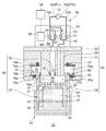
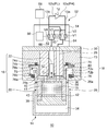
- FIGS. 1 and 2 are schematic diagrams showing a cryogenic refrigerator 10 according to an embodiment.
- the cryogenic refrigerator 10 is, for example, a gas-driven GM refrigerator.
- the cryogenic refrigerator 10 includes a compressor 12 for compressing a working gas (for example, helium gas) and a cold head 14 for cooling the working gas by adiabatic expansion.
- the compressor 12 has a compressor discharge port 12a and a compressor suction port 12b.
- the compressor discharge port 12a and the compressor suction port 12b function as a high pressure source and a low pressure source of the cryogenic refrigerator 10, respectively.
- the cold head 14 is also called an expander.
- the compressor 12 supplies a high pressure (PH) working gas to the cold head 14 from the compressor discharge port 12a.
- the cold head 14 is provided with a regenerator 15 for pre-cooling the working gas.
- the pre-cooled working gas is further cooled by expansion in the cold head 14.
- the working gas is collected at the compressor inlet 12b through the regenerator 15.
- the working gas cools the regenerator 15 when passing through the regenerator 15.
- the compressor 12 compresses the collected low-pressure (PL) working gas and supplies it to the cold head 14 again.
- the illustrated cold head 14 is a single-stage type. However, the cold head 14 may be a multi-stage.
- the cold head 14 includes an axial movable body 16 as a free piston driven by gas pressure, and a cold head housing 18 that is airtightly configured and houses the axial movable body 16.
- the cold head housing 18 supports the axially movable body 16 so as to be able to reciprocate in the axial direction, and is configured as a pressure vessel for working gas.
- the cold head 14 does not have a motor for driving the axially movable body 16 and a coupling mechanism (for example, a Scotch yoke mechanism).
- the axially movable body 16 includes a displacer 20 that can reciprocate in the axial direction (the vertical direction in FIG. 1, indicated by an arrow C), and a driving piston coaxially connected to the displacer 20 so as to drive the displacer 20 in the axial direction. 22.
- the drive piston 22 is rigidly connected to the displacer 20 so that the displacer 20 reciprocates in the axial direction integrally with the drive piston 22.
- the drive piston 22 has a smaller size than the displacer 20.
- the axial length of the drive piston 22 is shorter than that of the displacer 20, and the diameter of the drive piston 22 is also smaller than that of the displacer 20.
- the cold head housing 18 includes a displacer cylinder 26 that houses the displacer 20 and a piston cylinder 28 that houses the drive piston 22.
- the piston cylinder 28 is disposed coaxially with the displacer cylinder 26 and adjacent to the displacer cylinder 26 in the axial direction.
- the drive unit of the gas-driven cold head 14 includes a drive piston 22 and a piston cylinder 28.
- the volume of the piston cylinder 28 is smaller than that of the displacer cylinder 26.
- the axial length of the piston cylinder 28 is shorter than that of the displacer cylinder 26, and the diameter of the piston cylinder 28 is also smaller than that of the displacer cylinder 26.
- the axial reciprocation of the displacer 20 is guided by the displacer cylinder 26.
- the displacer 20 and the displacer cylinder 26 are each cylindrical members extending in the axial direction, and the inner diameter of the displacer cylinder 26 is equal to or slightly larger than the outer diameter of the displacer 20.
- axial reciprocation of the drive piston 22 is guided by a piston cylinder 28.
- the drive piston 22 and the piston cylinder 28 are each cylindrical members extending in the axial direction, and the inner diameter of the piston cylinder 28 matches or is slightly larger than the outer diameter of the drive piston 22.
- the axial stroke of the drive piston 22 is equal to the axial stroke of the displacer 20, and both move integrally over the entire stroke.
- the position of the drive piston 22 relative to the displacer 20 does not change during the axial reciprocation of the movable body 16.
- the first seal portion 32 is provided between the drive piston 22 and the piston cylinder 28.
- the first seal portion 32 is mounted on one of the drive piston 22 and the piston cylinder 28 and slides on the other of the drive piston 22 and the piston cylinder 28.
- the first seal portion 32 is formed of, for example, a seal member such as a slipper seal or an O-ring.
- the piston cylinder 28 is hermetically sealed with respect to the displacer cylinder 26 by the first seal portion 32. Since the first seal portion 32 is provided, there is no direct gas flow between the piston cylinder 28 and the displacer cylinder 26.
- the internal pressure of the piston cylinder 28 and the internal pressure of the displacer cylinder 26 can have different magnitudes.
- the displacer cylinder 26 is partitioned by the displacer 20 into an expansion chamber 34 and a room temperature chamber 36.
- the displacer 20 forms an expansion chamber 34 at one end in the axial direction with the displacer cylinder 26, and forms a room temperature chamber 36 with the displacer cylinder 26 at the other end in the axial direction.
- the room temperature chamber 36 can also be called a compression chamber.
- the cold head 14 is provided with a cooling stage 38 fixed to the displacer cylinder 26 so as to enclose the expansion chamber 34.
- the regenerator 15 is built in the displacer 20.
- the upper portion of the displacer 20 has an inlet channel 40 that connects the regenerator 15 to the room temperature chamber 36.
- the displacer 20 has an outlet flow path 42 in its cylindrical portion that connects the regenerator 15 to the expansion chamber 34.
- the outlet channel 42 may be provided in the lower lid of the displacer 20.
- the regenerator 15 includes an inlet retainer 41 inscribed in the upper lid and an outlet retainer 43 inscribed in the lower lid.
- the regenerator material may be, for example, a copper wire mesh.
- the retainer may be a wire mesh coarser than the cold storage material.
- the second seal portion 44 is provided between the displacer 20 and the displacer cylinder 26.
- the second seal portion 44 is, for example, a slipper seal, and is attached to a cylindrical portion or an upper lid portion of the displacer 20. Since the clearance between the displacer 20 and the displacer cylinder 26 is sealed by the second seal portion 44, there is no direct gas flow between the room temperature chamber 36 and the expansion chamber 34 (that is, the gas flow bypassing the regenerator 15).
- the working gas flows into the regenerator 15 from the room temperature chamber 36 through the inlet channel 40. More precisely, the working gas flows from the inlet passage 40 into the regenerator 15 through the inlet retainer 41. The working gas flows from the regenerator 15 into the expansion chamber 34 via the outlet retainer 43 and the outlet channel 42. When the working gas returns from the expansion chamber 34 to the room temperature chamber 36, it passes through the reverse route. That is, the working gas returns from the expansion chamber 34 to the room temperature chamber 36 through the outlet channel 42, the regenerator 15, and the inlet channel 40. The working gas that bypasses the regenerator 15 and flows through the clearance is blocked by the second seal portion 44.
- the cold head 14 is installed in the direction shown in the field where it is used. That is, the cold head 14 is installed vertically so that the displacer cylinder 26 is arranged vertically downward and the piston cylinder 28 is arranged vertically upward. As described above, when the cryogenic refrigerator 10 is installed in a posture in which the cooling stage 38 is directed downward in the vertical direction, the cryogenic refrigerator 10 has the highest refrigeration capacity. However, the arrangement of the cryogenic refrigerator 10 is not limited to this. Conversely, the cold head 14 may be installed in a posture in which the cooling stage 38 is directed vertically upward. Alternatively, the cold head 14 may be installed in a sideways or other orientation. The cold head 14 can be cooled even if it is installed in any posture.
- the end of the reciprocating stroke of the displacer 20 on the expansion chamber 34 side is called the bottom dead center of the displacer 20, and the end of the reciprocating stroke of the displacer 20 on the room temperature room 36 side is called the top dead center of the displacer 20.
- the movement of the displacer 20 toward the top dead center may be referred to as upward movement, and the movement of the displacer 20 toward the bottom dead center may be referred to as downward movement.
- these terms do not limit the attitude of the cold head 14.
- the expansion chamber 34 and the room temperature chamber 36 increase or decrease the volume complementarily. That is, when the displacer 20 moves down, the expansion chamber 34 becomes narrow and the room temperature chamber 36 becomes wide. The reverse is also true. Therefore, when the displacer 20 is located at the bottom dead center, the volume of the expansion chamber 34 is minimum (the volume of the room temperature chamber 36 is maximum). When the displacer 20 is located at the top dead center, the volume of the expansion chamber 34 becomes maximum (the volume of the room temperature chamber 36 becomes minimum).
- the cryogenic refrigerator 10 includes a working gas circuit 52 that connects the compressor 12 to the cold head 14.
- the working gas circuit 52 is configured to create a pressure difference between the piston cylinder 28 and the displacer cylinder 26 (ie, the expansion chamber 34 and / or the room temperature chamber 36). This pressure difference causes the axially movable body 16 to move in the axial direction. If the pressure of the displacer cylinder 26 with respect to the piston cylinder 28 is low, the drive piston 22 moves down, and accordingly, the displacer 20 also moves down. Conversely, if the pressure of the displacer cylinder 26 is high with respect to the piston cylinder 28, the drive piston 22 moves upward, and accordingly, the displacer 20 also moves upward.
- the working gas circuit 52 includes a valve section 54.
- the valve section 54 may be disposed adjacent to the piston cylinder 28 so as to be integrated with the cold head housing 18 and connected to the compressor 12 by piping.
- the valve portion 54 may be provided outside the cold head housing 18 and connected to the compressor 12 and the cold head 14 by piping.
- the valve section 54 includes an expansion chamber pressure switching valve (hereinafter, also referred to as a main pressure switching valve) 60 and a driving chamber pressure switching valve (hereinafter, also referred to as an auxiliary pressure switching valve) 62.
- the main pressure switching valve 60 has a main intake opening / closing valve V1 and a main exhaust opening / closing valve V2.
- the sub-pressure switching valve 62 has a sub-intake opening / closing valve V3 and a sub-exhaust opening / closing valve V4.
- the working gas circuit 52 includes a high-pressure line 13a and a low-pressure line 13b that connect the compressor 12 to the valve unit 54.
- the high-pressure line 13a extends from the compressor discharge port 12a, branches on the way, and is connected to the main intake opening / closing valve V1 and the auxiliary intake opening / closing valve V3.
- the low-pressure line 13b extends from the compressor inlet 12b, branches on the way, and is connected to the main exhaust valve V2 and the auxiliary exhaust valve V4.
- the working gas circuit 52 includes a main communication path 64 and a sub communication path 66 for connecting the cold head 14 to the valve section 54.
- the main communication passage 64 connects the displacer cylinder 26 to the main pressure switching valve 60.
- the main communication passage 64 extends from the room temperature chamber 36, branches on the way, and is connected to the main intake opening / closing valve V1 and the main exhaust opening / closing valve V2.
- the auxiliary communication passage 66 connects the piston cylinder 28 to the auxiliary pressure switching valve 62.
- the auxiliary communication passage 66 extends from the piston cylinder 28, branches off in the middle, and is connected to the auxiliary intake opening / closing valve V3 and the auxiliary exhaust opening / closing valve V4.
- the main pressure switching valve 60 is configured to selectively connect the compressor discharge port 12a or the compressor suction port 12b to the room temperature chamber 36 of the displacer cylinder 26.
- the main intake opening / closing valve V1 and the main exhaust opening / closing valve V2 are exclusively opened. That is, the simultaneous opening of the main intake opening / closing valve V1 and the main exhaust opening / closing valve V2 is prohibited.
- the main intake open / close valve V1 and the main exhaust open / close valve V2 may be temporarily closed together.
- the main exhaust opening / closing valve V2 when the main exhaust opening / closing valve V2 is open, the main intake opening / closing valve V1 is closed.
- the high-pressure PH working gas is expanded and decompressed in the expansion chamber 34.
- the working gas flows from the expansion chamber 34 to the room temperature chamber 36 through the regenerator 15.
- Working gas flows from the displacer cylinder 26 to the compressor suction port 12b through the main communication passage 64 and the low-pressure line 13b.
- the low-pressure PL working gas is recovered from the cold head 14 to the compressor 12.
- the main exhaust valve V2 When the main exhaust valve V2 is closed, the collection of the working gas from the expansion chamber 34 to the compressor 12 is stopped.
- the auxiliary pressure switching valve 62 is configured to selectively connect the compressor discharge port 12a or the compressor suction port 12b to the piston cylinder 28.
- the auxiliary pressure switching valve 62 is configured such that the auxiliary intake opening / closing valve V3 and the auxiliary exhaust opening / closing valve V4 are exclusively opened. That is, the simultaneous opening of the auxiliary intake opening / closing valve V3 and the auxiliary exhaust opening / closing valve V4 is prohibited. Note that the auxiliary intake opening / closing valve V3 and the auxiliary exhaust opening / closing valve V4 may be temporarily closed together.
- auxiliary exhaust opening / closing valve V4 when the auxiliary exhaust opening / closing valve V4 is open, the auxiliary intake opening / closing valve V3 is closed.
- Working gas is recovered from the piston cylinder 28 to the compressor suction port 12b through the auxiliary communication passage 66 and the low-pressure line 13b, and the pressure of the piston cylinder 28 is reduced to the low pressure PL.
- the sub exhaust valve V4 is closed, the collection of the working gas from the piston cylinder 28 to the compressor 12 is stopped.
- the main pressure switching valve 60 generates a periodic pressure fluctuation of the high pressure PH and the low pressure PL in the expansion chamber 34.
- the sub-pressure switching valve 62 generates periodic pressure fluctuations of the high pressure PH and the low pressure PL in the piston cylinder 28.
- the auxiliary pressure switching valve 62 is configured to control the pressure of the piston cylinder 28 so that the drive piston 22 drives the displacer 20 to reciprocate in the axial direction.
- the pressure fluctuations in the piston cylinder 28 are generated in the same cycle as the pressure fluctuations in the expansion chamber 34 and in substantially the opposite phase.
- the valve section 54 may take the form of a rotary valve.
- a group of valves (V1 to V4) are incorporated in the valve section 54 and are driven synchronously.
- the valve section 54 is configured such that the valves (V1 to V4) are appropriately switched by the rotational sliding of the valve disk (or the valve rotor) with respect to the valve body (or the valve stator).
- the group of valves (V1 to V4) are switched at the same cycle during the operation of the cryogenic refrigerator 10, whereby the four open / close valves (V1 to V4) change the open / close state periodically.
- the four open / close valves (V1 to V4) are opened / closed in different phases.
- the cryogenic refrigerator 10 may include a rotation drive source 56 connected to the valve unit 54 to rotate the valve unit 54.
- the rotation drive source 56 is mechanically connected to the valve unit 54.
- the rotation drive source 56 is, for example, a motor. However, the rotation drive source 56 is not mechanically connected to the axially movable body 16.
- the cryogenic refrigerator 10 may include a control unit 58 that controls the valve unit 54.
- the control unit 58 may control the rotation drive source 56.
- the group of valves (V1-V4) may take the form of a plurality of individually controllable valves.
- Each of the valves (V1 to V4) may be an electromagnetic on-off valve.
- the valves (V1 to V4) are electrically connected to the control unit 58 instead of providing the rotation drive source 56.
- the control unit 58 may control the opening and closing of each valve (V1 to V4).
- FIG. 1 shows a state where the displacer 20 is located at the bottom dead center
- FIG. 2 shows a state where the displacer 20 is located at the top dead center.
- the cold head 14 includes a collar 70 and a color chamber 72 divided into an upper section 72 a and a lower section 72 b by the collar 70.
- the collar 70 is rigidly connected to the displacer 20 so as to reciprocate with the displacer 20 and forms a part of the axially movable body 16. As described later, the reciprocating stroke of the collar 70 in the color chamber 72 determines the reciprocating stroke of the displacer 20.
- the displacer cylinder 26 includes a cylinder flange 26a that defines a cylinder upper opening.
- the cylinder flange 26a extends radially outward from the axial upper end of the displacer cylinder 26.
- the cold head housing 18 includes a top plate 30 and a sleeve 73.
- the piston cylinder 28 and the sleeve 73 are fixed to the top 30, and the valve unit 54 is mounted on the top 30.
- the cylinder flange 26a is connected to the top plate 30 via a sleeve 73.
- the sleeve 73 is arranged outside the piston cylinder 28 so as to surround the piston cylinder 28.
- the collar 70 includes a cylindrical main body 70a and a collar upper end 70b.
- the main body 70a has substantially the same outer diameter as the displacer 20, and extends upward from the room temperature room 36 side of the displacer 20.
- the inner diameter of the main body 70a is larger than the outer diameter of the piston cylinder 28.
- the collar upper end 70 b exists outside the outer diameter of the displacer 20.
- the color chamber 72 is divided into an upper section 72a and a lower section 72b by a collar upper end 70b.
- the color chamber 72 communicates with the room temperature chamber 36.
- the cold head 14 also includes an upper bumper 74 provided in the upper section 72a so as to reduce interference between the displacer 20 and the displacer cylinder 26 when the displacer 20 is at the top dead center.
- the upper bumper 74 is installed on the upper surface of the collar chamber 72, and has an upper cushioning member 74a and an upper retainer 74b.
- the upper bumper 74 is attached to the sleeve 73, for example.
- the upper cushioning member 74a is an annular member made of resin such as an O-ring, and is sandwiched between the upper surface of the collar chamber 72 and the upper retainer 74b.
- the upper retainer 74b is formed of, for example, a resin material. Note that the upper retainer 74b may not be provided.
- the upper bumper 74 contacts the collar 70 when the displacer 20 is located at the top dead center, and prevents the collision between the displacer 20 and the displacer cylinder 26 on the room temperature room 36 side. Collar upper end 70b engages upper bumper 74 in collar chamber 72 before displacer 20 strikes piston cylinder 28 as displacer 20 moves up. At this time, the upper end 70b of the collar contacts the upper retainer 74b, the upper cushioning material 74a is compressed, and the impact is absorbed.
- the cold head 14 includes a lower bumper 76 provided in the lower section 72b so as to reduce interference between the displacer 20 and the displacer cylinder 26 when the displacer 20 is at the bottom dead center.
- the lower bumper 76 is installed on the lower surface of the collar chamber 72, and has a lower buffer 76a and a lower retainer 76b.
- the lower bumper 76 is attached to, for example, the cylinder flange 26a.
- the lower bumper 76 may be attached to the sleeve 73.
- the lower cushioning member 76a is a resin-made annular member such as an O-ring, and is sandwiched between the lower surface of the collar chamber 72 and the lower retainer 76b.
- the lower retainer 76b is formed of, for example, a resin material. Note that the lower retainer 76b may not be provided.
- the lower bumper 76 contacts the collar 70 when the displacer 20 is located at the bottom dead center, and prevents the collision between the displacer 20 and the displacer cylinder 26 on the expansion chamber 34 side.
- the collar upper end 70b engages the lower bumper 76 in the collar chamber 72 before the displacer 20 collides with the displacer cylinder 26 on the expansion chamber 34 side when the displacer 20 moves down.
- the upper end 70b of the collar comes into contact with the lower retainer 76b, the lower cushioning material 76a is compressed, and the impact is absorbed.
- the upper section 72a communicates with the room temperature chamber 36.
- a first gap 78a is formed between the outer peripheral surface of the piston cylinder 28 and the inner peripheral surface of the collar 70, and the working gas can flow between the room temperature chamber 36 and the upper section 72a through the first gap 78a.
- the lower section 72b communicates with the upper section 72a.
- a second gap 78b is formed between the inner peripheral surface of the sleeve 73 and the outer peripheral surface of the collar upper end 70b, and the working gas can flow between the upper section 72a and the lower section 72b through the second gap 78b.
- the displacer 20 when the displacer 20 is located at the bottom dead center, the upper end 70b of the collar contacts the lower bumper 76, and the communication between the lower section 72b and the upper section 72a through the second gap 78b is shut off.
- the upper end 70b of the collar contacts the upper bumper 74, and the communication between the lower section 72b and the upper section 72a through the second gap 78b is shut off.
- the lower compartment 72b communicates with the room compartment 36 through the upper compartment 72a and operates between the room compartment 36 and the lower compartment 72b. Gas can flow. Further, since the lower section 72 b is sealed by the second seal portion 44, the lower section 72 b does not communicate with the expansion chamber 34.
- the cold head 14 also includes a communication path 80 that ensures communication between the upper section 72a and the lower section 72b when the displacer 20 is at the bottom dead center.
- the communication passage 80 is formed in the collar 70 such that the upper section 72a communicates with the lower section 72b when the upper end 70b of the collar is in contact with the lower bumper 76.
- the communication passage 80 is formed so as to penetrate the collar 70 (for example, the collar upper end 70b) from the upper section 72a to the lower section 72b, and it is sufficient that at least one communication path 80 is provided in the circumferential direction.
- the communication passage 80 is formed at the collar upper end 70b at a position radially inward with respect to the lower bumper 76. It is formed.
- the communication passage 80 may be formed so as to penetrate the main body 70 a of the collar 70.
- the first gap 78a, the second gap 78b, and the communication path 80 function as flow path resistance. Therefore, when the displacer 20 reciprocates, the upper section 72a and the lower section 72b can each generate a gas spring force. As the displacer 20 moves upward, the collar upper end 70b also moves upward, and the upper section 72a becomes narrower. At this time, the gas in the upper section 72a is compressed, and the pressure increases. The pressure in the upper section 72a acts downward on the upper surface of the collar upper end 70b. Thus, the upper section 72a generates a gas spring force that opposes the upward movement of the collar 70 and the displacer 20.
- the lower section 72b when the displacer 20 moves down, the lower section 72b generates a gas spring force that opposes the movement of the collar 70 and the displacer 20.
- the upper section 72a and the lower section 72b may be referred to as an upper gas spring chamber and a lower gas spring chamber, respectively.
- the gas spring force helps reduce vibration and noise that can occur when the collar 70 contacts the upper bumper 74 and the lower bumper 76.
- the operation of the cryogenic refrigerator 10 will be described.
- the main intake open / close valve V1 is opened, and the main exhaust open / close valve V2 is closed.
- Working gas is supplied from the compressor discharge port 12a to the displacer cylinder 26 of the cold head 14 through the main intake opening / closing valve V1, and the expansion chamber 34 and the room temperature chamber 36 are set to a high pressure PH.
- the exhaust from the piston cylinder 28 is performed simultaneously with the intake into the expansion chamber 34.
- the auxiliary intake opening / closing valve V3 is closed, and the auxiliary exhaust opening / closing valve V4 is opened.
- the working gas is discharged from the piston cylinder 28 to the compressor inlet 12b through the sub-exhaust opening / closing valve V4, and the pressure of the piston cylinder 28 is reduced to a low pressure PL.
- the driving force due to the differential pressure (PH-PL) between the piston cylinder 28 and the expansion chamber 34 acts on the driving piston 22 upward.
- the displacer 20 moves from the bottom dead center to the top dead center together with the drive piston 22.
- the volume of the expansion chamber 34 is increased and filled with the high-pressure gas.
- the collar 70 moves upward together with the displacer 20. Collar 70 contacts upper bumper 74 before displacer 20 collides with the hot end of displacer cylinder 26 (eg, piston cylinder 28). The upper cushioning material 74a is compressed, and the impact is absorbed. During the upward movement of the collar 70, the upper section 72a communicates with the room temperature chamber 36 through the first gap 78a, and the lower section 72b communicates with the upper section 72a through the second gap 78b and the communication passage 80. The lower compartment 72b is at a high pressure PH as in the room temperature chamber 36.
- the exhaust process of the cryogenic refrigerator 10 is started.
- the main exhaust open / close valve V2 is opened, and the main intake open / close valve V1 is closed.
- the high-pressure gas is expanded and cooled in the expansion chamber 34.
- the expanded gas is collected in the compressor inlet 12b through the room temperature chamber 36 while cooling the regenerator 15.
- the expansion chamber 34 and the room temperature chamber 36 have a low pressure PL.
- the intake to the piston cylinder 28 is performed.
- the sub exhaust valve V4 is closed, and the sub intake valve V3 is opened.
- Working gas is supplied from the compressor discharge port 12a to the piston cylinder 28 through the auxiliary intake opening / closing valve V3, and the pressure of the piston cylinder 28 is increased to a high pressure PH.
- the driving force due to the differential pressure (PH-PL) between the piston cylinder 28 and the expansion chamber 34 acts on the driving piston 22 in a downward direction.
- the displacer 20 moves from the top dead center to the bottom dead center together with the drive piston 22.
- the volume of the expansion chamber 34 is reduced and the low-pressure gas is discharged.
- the collar 70 moves down together with the displacer 20. Collar 70 contacts lower bumper 76 before displacer 20 collides with the cold end of displacer cylinder 26.
- the lower cushioning material 76a is compressed, and the impact is absorbed.
- the upper section 72a communicates with the room temperature chamber 36 through the first gap 78a
- the lower section 72b communicates with the upper section 72a through the second gap 78b and the communication passage 80.
- the lower compartment 72b is at a low pressure PL similarly to the room temperature chamber 36.
- the cryogenic refrigerator 10 cools the cooling stage 38 by repeating such a refrigeration cycle (that is, a GM cycle). Thereby, the cryogenic refrigerator 10 can cool the object to be cooled (not shown) thermally coupled to the cooling stage 38.
- a refrigeration cycle that is, a GM cycle
- cryogenic refrigerator 10 is of a color bumper type, interference (for example, collision) between the displacer 20 and the displacer cylinder 26 due to contact between the collar 70 and the bumpers (74, 76) is prevented, and vibration and noise are reduced. be able to.
- a typical color bumper type gas driven cryogenic refrigerator does not have the communication passage 80 unlike the above-described embodiment.
- the low section PL working gas may be sealed in the lower section 72b.
- the upper end 70b of the collar can be pressed against the lower bumper 76 by the differential pressure (PH-PL). This differential pressure can prevent the displacer 20 from moving up.
- the cryogenic refrigerator 10 includes the communication passage 80 formed in the collar 70 so as to guarantee the communication between the upper section 72a and the lower section 72b when the displacer 20 is at the bottom dead center. Therefore, even when the collar 70 is located at the bottom dead center and the upper end 70 b of the collar is in contact with the lower bumper 76, the lower section 72 b communicates with the upper section 72 a through the communication passage 80. The lower section 72b is not sealed. The differential pressure that can occur between the upper section 72a and the lower section 72b is reduced or eliminated through the communication passage 80, so that the upward movement of the displacer 20 is not hindered. Therefore, the displacer 20 can move from the bottom dead center toward the top dead center.
- the communication passage 80 is formed in the collar 70. In this way, it is easy to form the communication path 80 in manufacturing.
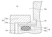
- FIG. 3 is a diagram schematically showing a collar and a bumper according to another embodiment.
- the communication passage 80 may be formed in the collar chamber 72 instead of being formed in the main body 70a or the upper end 70b of the collar 70.
- the communication passage 80 may be formed in the lower bumper 76, for example.
- the communication passage 80 may be, for example, a groove formed on the upper surface of the lower retainer 76b opposite to the lower cushioning material 76a.
- the communication path 80 formed in the color chamber 72 shown in FIG. 3 is applicable to the cryogenic refrigerator 10 shown in FIGS. 1 and 2 or another color bumper type gas driven cryogenic refrigerator.
- the communication path 80 can guarantee the communication between the upper section 72a and the lower section 72b when the displacer 20 is at the bottom dead center. Since the differential pressure that can occur between the upper section 72a and the lower section 72b is reduced or eliminated through the communication passage 80, the displacer 20 can be easily moved from the bottom dead center to the top dead center.
- the communication path 80 may be a flow path formed in the cold head housing 18.
- the communication passage 80 may extend from the upper section 72a to the lower section 72b via the sleeve 73 and the cylinder flange 26a. Even in this case, the communication path 80 can guarantee the communication between the upper section 72a and the lower section 72b when the displacer 20 is at the bottom dead center.
- the collar upper end 70b is provided radially outward with respect to the displacer 20, but such a specific shape is not essential.
- the collar upper end 70b may extend radially inward from the main body 70a and may be present inside the outer diameter of the displacer 20.
- the collar chamber 72 is not formed on the sleeve 73 side as described above, but is formed on the piston cylinder 28 side.
- the upper bumper 74 is mounted on the upper surface of the color chamber 72 and is disposed in the upper section 72a
- the lower bumper 76 is mounted on the lower surface of the color chamber 72 and is disposed in the lower section 72b.
- the upper bumper 74 and the lower bumper 76 may be attached to the collar 70.
- the upper bumper 74 may be mounted on the upper surface of the upper collar 70b and disposed in the upper compartment 72a
- the lower bumper 76 may be mounted on the lower surface of the upper collar 70b and disposed in the lower compartment 72b. Even in this case, interference (for example, collision) between the displacer 20 and the displacer cylinder 26 due to the contact between the color chamber 72 and the bumpers (74, 76) can be prevented, and vibration and noise can be reduced.
- the GM refrigerator is described as an example, but the design of the color bumper system having the communication passage 80 described above can be applied to other gas-driven cryogenic refrigerators.
- the terms "displacer” and “drive piston” in the above description may mean “first piston” and “second piston”, respectively.
- the present invention can be used in the field of cryogenic refrigerators.
- cryogenic refrigerator ⁇ 20 ⁇ displacer, ⁇ 70 ⁇ color, ⁇ 72 ⁇ color room, ⁇ 72a ⁇ upper compartment, ⁇ 72b ⁇ lower compartment, ⁇ 76 ⁇ lower bumper, ⁇ 80 ⁇ communicating passage.
Landscapes
- Engineering & Computer Science (AREA)
- Physics & Mathematics (AREA)
- Mechanical Engineering (AREA)
- Thermal Sciences (AREA)
- General Engineering & Computer Science (AREA)
- Compressor (AREA)
- Compressors, Vaccum Pumps And Other Relevant Systems (AREA)
Priority Applications (2)
| Application Number | Priority Date | Filing Date | Title |
|---|---|---|---|
| CN201980057658.7A CN112639378B (zh) | 2018-09-07 | 2019-08-06 | 超低温制冷机 |
| US17/185,996 US11774147B2 (en) | 2018-09-07 | 2021-02-26 | Cryocooler |
Applications Claiming Priority (2)
| Application Number | Priority Date | Filing Date | Title |
|---|---|---|---|
| JP2018-167725 | 2018-09-07 | ||
| JP2018167725A JP7195824B2 (ja) | 2018-09-07 | 2018-09-07 | 極低温冷凍機 |
Related Child Applications (1)
| Application Number | Title | Priority Date | Filing Date |
|---|---|---|---|
| US17/185,996 Continuation US11774147B2 (en) | 2018-09-07 | 2021-02-26 | Cryocooler |
Publications (1)
| Publication Number | Publication Date |
|---|---|
| WO2020049936A1 true WO2020049936A1 (ja) | 2020-03-12 |
Family
ID=69722417
Family Applications (1)
| Application Number | Title | Priority Date | Filing Date |
|---|---|---|---|
| PCT/JP2019/031007 Ceased WO2020049936A1 (ja) | 2018-09-07 | 2019-08-06 | 極低温冷凍機 |
Country Status (4)
| Country | Link |
|---|---|
| US (1) | US11774147B2 (enExample) |
| JP (1) | JP7195824B2 (enExample) |
| CN (1) | CN112639378B (enExample) |
| WO (1) | WO2020049936A1 (enExample) |
Cited By (1)
| Publication number | Priority date | Publication date | Assignee | Title |
|---|---|---|---|---|
| US20230129966A1 (en) * | 2021-10-26 | 2023-04-27 | Sumitomo (Shi) Cryogenics Of America, Inc. | Gas energized seal for gifford-mcmahon expander |
Families Citing this family (2)
| Publication number | Priority date | Publication date | Assignee | Title |
|---|---|---|---|---|
| JP7640298B2 (ja) * | 2021-03-15 | 2025-03-05 | 住友重機械工業株式会社 | 極低温冷凍機 |
| JPWO2023149130A1 (enExample) * | 2022-02-04 | 2023-08-10 |
Citations (5)
| Publication number | Priority date | Publication date | Assignee | Title |
|---|---|---|---|---|
| JPH0244662U (enExample) * | 1988-09-20 | 1990-03-27 | ||
| JPH08303889A (ja) * | 1995-05-09 | 1996-11-22 | Daikin Ind Ltd | 極低温冷凍機 |
| JP2003523496A (ja) * | 2000-02-15 | 2003-08-05 | インターマグネティクス ゼネラル コーポレイション | 空気圧駆動gm型ディスプレーサを有する低振動冷却装置 |
| JP2018036042A (ja) * | 2016-07-25 | 2018-03-08 | スミトモ (エスエイチアイ) クライオジェニックス オブ アメリカ インコーポレイテッドSumitomo(SHI)Cryogenics of America,Inc. | 騒音および振動を低減するためのカラーバンパを備えた極低温膨張機 |
| WO2018101271A1 (ja) * | 2016-11-30 | 2018-06-07 | 住友重機械工業株式会社 | Gm冷凍機 |
Family Cites Families (10)
| Publication number | Priority date | Publication date | Assignee | Title |
|---|---|---|---|---|
| DE3044427C2 (de) * | 1980-11-26 | 1986-10-30 | Leybold-Heraeus GmbH, 5000 Köln | Verdränger für Tieftemperatur-Kältemaschinen |
| US4526008A (en) * | 1983-03-21 | 1985-07-02 | Texas Instruments Incorporated | Pneumatically controlled split cycle cooler |
| JPH02197765A (ja) | 1989-01-25 | 1990-08-06 | Daikin Ind Ltd | 極低温冷凍機の衝撃吸収装置 |
| JPH08313094A (ja) * | 1995-05-16 | 1996-11-29 | Toshiba Corp | 蓄冷式冷凍機 |
| JP2007205608A (ja) * | 2006-01-31 | 2007-08-16 | Sumitomo Heavy Ind Ltd | 蓄冷器式冷凍機 |
| JP6202483B2 (ja) * | 2012-06-12 | 2017-09-27 | 住友重機械工業株式会社 | 極低温冷凍機 |
| JP6109057B2 (ja) * | 2013-12-16 | 2017-04-05 | 住友重機械工業株式会社 | 蓄冷器式冷凍機 |
| JP6188619B2 (ja) * | 2014-04-02 | 2017-08-30 | 住友重機械工業株式会社 | 極低温冷凍機 |
| WO2018181396A1 (ja) * | 2017-03-30 | 2018-10-04 | 住友重機械工業株式会社 | 極低温冷凍機および磁気シールド |
| CN108931067B (zh) * | 2017-05-24 | 2020-11-03 | 中南大学 | 一种蒸汽压缩制冷系统驱动的脉管式制冷装置 |
-
2018
- 2018-09-07 JP JP2018167725A patent/JP7195824B2/ja active Active
-
2019
- 2019-08-06 CN CN201980057658.7A patent/CN112639378B/zh active Active
- 2019-08-06 WO PCT/JP2019/031007 patent/WO2020049936A1/ja not_active Ceased
-
2021
- 2021-02-26 US US17/185,996 patent/US11774147B2/en active Active
Patent Citations (5)
| Publication number | Priority date | Publication date | Assignee | Title |
|---|---|---|---|---|
| JPH0244662U (enExample) * | 1988-09-20 | 1990-03-27 | ||
| JPH08303889A (ja) * | 1995-05-09 | 1996-11-22 | Daikin Ind Ltd | 極低温冷凍機 |
| JP2003523496A (ja) * | 2000-02-15 | 2003-08-05 | インターマグネティクス ゼネラル コーポレイション | 空気圧駆動gm型ディスプレーサを有する低振動冷却装置 |
| JP2018036042A (ja) * | 2016-07-25 | 2018-03-08 | スミトモ (エスエイチアイ) クライオジェニックス オブ アメリカ インコーポレイテッドSumitomo(SHI)Cryogenics of America,Inc. | 騒音および振動を低減するためのカラーバンパを備えた極低温膨張機 |
| WO2018101271A1 (ja) * | 2016-11-30 | 2018-06-07 | 住友重機械工業株式会社 | Gm冷凍機 |
Cited By (1)
| Publication number | Priority date | Publication date | Assignee | Title |
|---|---|---|---|---|
| US20230129966A1 (en) * | 2021-10-26 | 2023-04-27 | Sumitomo (Shi) Cryogenics Of America, Inc. | Gas energized seal for gifford-mcmahon expander |
Also Published As
| Publication number | Publication date |
|---|---|
| CN112639378B (zh) | 2022-09-09 |
| US11774147B2 (en) | 2023-10-03 |
| CN112639378A (zh) | 2021-04-09 |
| JP2020041718A (ja) | 2020-03-19 |
| US20210180834A1 (en) | 2021-06-17 |
| JP7195824B2 (ja) | 2022-12-26 |
Similar Documents
| Publication | Publication Date | Title |
|---|---|---|
| US11408406B2 (en) | GM cryocooler and method of operating GM cryocooler | |
| US11221079B2 (en) | Cryocooler and rotary valve unit for cryocooler | |
| US11774147B2 (en) | Cryocooler | |
| JP6966886B2 (ja) | 騒音および振動を低減するためのカラーバンパを備えた極低温膨張機 | |
| US11971108B2 (en) | Rotary valve of cryocooler and cryocooler | |
| US11384963B2 (en) | GM cryocooler | |
| JP6573845B2 (ja) | 極低温冷凍機 | |
| US11333407B2 (en) | GM cryocooler with buffer volume communicating with drive chamber | |
| WO2018101273A1 (ja) | Gm冷凍機およびgm冷凍機の運転方法 | |
| JP2017048937A (ja) | 極低温冷凍機 | |
| JP6842373B2 (ja) | 極低温冷凍機 | |
| JP6998776B2 (ja) | Gm冷凍機 | |
| US11530847B2 (en) | Cryocooler and flow path switching mechanism of cryocooler | |
| JP6532392B2 (ja) | 極低温冷凍機 | |
| CN112236628B (zh) | 脉冲管制冷机 | |
| JP2015137798A (ja) | 極低温冷凍機 | |
| JP6654103B2 (ja) | Gm冷凍機 | |
| JPS6361582B2 (enExample) |
Legal Events
| Date | Code | Title | Description |
|---|---|---|---|
| 121 | Ep: the epo has been informed by wipo that ep was designated in this application |
Ref document number: 19857801 Country of ref document: EP Kind code of ref document: A1 |
|
| NENP | Non-entry into the national phase |
Ref country code: DE |
|
| 122 | Ep: pct application non-entry in european phase |
Ref document number: 19857801 Country of ref document: EP Kind code of ref document: A1 |