WO2020049697A1 - 作業機 - Google Patents
作業機 Download PDFInfo
- Publication number
- WO2020049697A1 WO2020049697A1 PCT/JP2018/033096 JP2018033096W WO2020049697A1 WO 2020049697 A1 WO2020049697 A1 WO 2020049697A1 JP 2018033096 W JP2018033096 W JP 2018033096W WO 2020049697 A1 WO2020049697 A1 WO 2020049697A1
- Authority
- WO
- WIPO (PCT)
- Prior art keywords
- fuel
- fuel tank
- tank
- breather
- opening
- Prior art date
- Legal status (The legal status is an assumption and is not a legal conclusion. Google has not performed a legal analysis and makes no representation as to the accuracy of the status listed.)
- Ceased
Links
Images



Classifications
-
- F—MECHANICAL ENGINEERING; LIGHTING; HEATING; WEAPONS; BLASTING
- F02—COMBUSTION ENGINES; HOT-GAS OR COMBUSTION-PRODUCT ENGINE PLANTS
- F02B—INTERNAL-COMBUSTION PISTON ENGINES; COMBUSTION ENGINES IN GENERAL
- F02B63/00—Adaptations of engines for driving pumps, hand-held tools or electric generators; Portable combinations of engines with engine-driven devices
- F02B63/04—Adaptations of engines for driving pumps, hand-held tools or electric generators; Portable combinations of engines with engine-driven devices for electric generators
- F02B63/044—Adaptations of engines for driving pumps, hand-held tools or electric generators; Portable combinations of engines with engine-driven devices for electric generators the engine-generator unit being placed on a frame or in an housing
- F02B63/048—Portable engine-generator combinations
-
- F—MECHANICAL ENGINEERING; LIGHTING; HEATING; WEAPONS; BLASTING
- F02—COMBUSTION ENGINES; HOT-GAS OR COMBUSTION-PRODUCT ENGINE PLANTS
- F02B—INTERNAL-COMBUSTION PISTON ENGINES; COMBUSTION ENGINES IN GENERAL
- F02B63/00—Adaptations of engines for driving pumps, hand-held tools or electric generators; Portable combinations of engines with engine-driven devices
- F02B63/04—Adaptations of engines for driving pumps, hand-held tools or electric generators; Portable combinations of engines with engine-driven devices for electric generators
- F02B63/044—Adaptations of engines for driving pumps, hand-held tools or electric generators; Portable combinations of engines with engine-driven devices for electric generators the engine-generator unit being placed on a frame or in an housing
-
- F—MECHANICAL ENGINEERING; LIGHTING; HEATING; WEAPONS; BLASTING
- F02—COMBUSTION ENGINES; HOT-GAS OR COMBUSTION-PRODUCT ENGINE PLANTS
- F02M—SUPPLYING COMBUSTION ENGINES IN GENERAL WITH COMBUSTIBLE MIXTURES OR CONSTITUENTS THEREOF
- F02M37/00—Apparatus or systems for feeding liquid fuel from storage containers to carburettors or fuel-injection apparatus; Arrangements for purifying liquid fuel specially adapted for, or arranged on, internal-combustion engines
- F02M37/0076—Details of the fuel feeding system related to the fuel tank
- F02M37/0082—Devices inside the fuel tank other than fuel pumps or filters
-
- F—MECHANICAL ENGINEERING; LIGHTING; HEATING; WEAPONS; BLASTING
- F02—COMBUSTION ENGINES; HOT-GAS OR COMBUSTION-PRODUCT ENGINE PLANTS
- F02B—INTERNAL-COMBUSTION PISTON ENGINES; COMBUSTION ENGINES IN GENERAL
- F02B63/00—Adaptations of engines for driving pumps, hand-held tools or electric generators; Portable combinations of engines with engine-driven devices
- F02B63/04—Adaptations of engines for driving pumps, hand-held tools or electric generators; Portable combinations of engines with engine-driven devices for electric generators
- F02B63/044—Adaptations of engines for driving pumps, hand-held tools or electric generators; Portable combinations of engines with engine-driven devices for electric generators the engine-generator unit being placed on a frame or in an housing
- F02B2063/045—Frames for generator-engine sets
Definitions
- the present invention relates to a working machine having a fuel tank.
- Examples of the working machine include a portable generator (also referred to as an engine generator) that generates power using liquid fuel stored in a fuel tank (for example, see Patent Document 1).
- a portable generator also referred to as an engine generator
- a portable generator in which a breather passage is provided in a tank cap detachably provided in a fuel tank, and the breather passage is manually opened and closed. By closing the breather passage during transportation or storage of the portable generator, fuel leakage from the breather passage can be avoided even if the portable generator falls over during transportation.
- a portable generator by opening the breather passage, it is possible to avoid a situation in which the fuel tank becomes negative pressure due to a decrease in fuel and the supply of fuel becomes difficult.
- the fuel tank is closed when the breather passage is closed during transportation or storage, so the pressure in the fuel tank increases due to the vapor pressure of gasoline as the outside air temperature increases, and conversely, when the temperature is low, The pressure inside the fuel tank becomes negative.
- it is necessary to improve the strength of the fuel tank and the pressure resistance of the fuel system components.
- it is necessary to close the breather passage at the time of transportation or storage and open the breather passage at the start of use, which is a factor that hinders user convenience. If the user forgets to close the breather passage, fuel leakage may occur when the portable generator falls over. Further, if the breather passage is forgotten to be opened at the start of use, there is a possibility that power generation may be suddenly stopped.
- an object of the present invention is to suppress a change in pressure in a fuel tank without performing an operation of opening and closing a breather passage, and to suppress leakage of liquid fuel even if the fuel tank is inclined in a predetermined direction.
- the fuel tank has a tank shape having a fuel supply port and expanding to a position higher than the fuel supply port, A breather passage communicating between the inside and the outside of the tank bulging portion, which is a portion higher than the fuel supply port, wherein the breather passage is provided inside the tank bulging portion when the working machine is inclined in a predetermined first direction. And an opening at a position above the liquid fuel, and including a position above the liquid fuel when the work machine is inclined in a second direction different from the first direction.
- the first breather passage extends along the first direction from the opening of the breather passage, and then extends downward along a side wall of the fuel tank. After extending along the second direction from the opening of the breather passage, the breather passage turns back, extends along the first direction, and then extends downward along the side wall of the fuel tank.
- the first and second breather passages have a downward slope toward each opening.
- the first direction is one of left and right directions
- the second direction is the other direction
- each opening of the first and second breather passages is connected to the fuel tank. It is characterized in that it is provided at a front-rear intermediate position.
- the first and second breather passages are arranged in the fuel tank, and are connected to a canister or an air cleaner case after coming out of a predetermined location of the fuel tank.
- the first and second breather passages are characterized in that a portion of each passage other than the opening is disposed outside the fuel tank and is connected to a canister or an air cleaner case.
- the fuel tank further includes a wave preventing member arranged around the opening so as to prevent the wave of the liquid fuel from entering the opening.
- the working machine is a portable generator that generates power using the liquid fuel in the fuel tank.
- the fuel tank of the working machine has a breather passage communicating between the inside and the outside of the tank bulging portion which is a portion higher than the fuel supply port, and the breather passage is provided when the working machine is inclined in a predetermined first direction.
- An opening at a position above the liquid fuel in the fuel tank in the tank bulging portion, and when the working machine is inclined in a second direction different from the first direction, the liquid fuel A first breather passage routed to include a position above the liquid fuel, and a position above the liquid fuel in the tank bulging portion when the work implement is inclined in the second direction.
- FIG. 1 is a perspective view showing the appearance of the engine generator according to the first embodiment of the present invention.
- FIG. 2 is a diagram schematically showing an internal configuration of the engine generator.
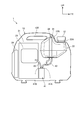
- FIG. 3 is a perspective view showing the fuel tank together with the breather passage.
- FIG. 4 is a top view showing the fuel tank together with the breather passage.
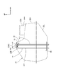
- FIG. 5 is a side sectional view showing the fuel tank together with the breather passage.
- FIG. 6 is a view of the fuel tank viewed from the rear together with the breather passage.
- FIG. 7 is a diagram schematically illustrating a state before the fuel tank is tilted and a state where the fuel tank is tilted 90 ° right and left.
- FIG. 8 is a perspective view showing a fuel tank of the engine generator according to the second embodiment together with peripheral components.
- FIG. 9 is a view of the inside of the fuel tank of the engine generator according to the third embodiment as viewed from the rear side.
- FIG. 10 is a view of the inside of the fuel tank viewed from the right side.
- FIG. 1 is a perspective view showing the appearance of the engine generator according to the first embodiment of the present invention.
- the engine generator 1 is a small, lightweight, portable generator that can be carried relatively easily, and is entirely formed in a substantially rectangular parallelepiped shape.
- the engine generator 1 includes a substantially rectangular parallelepiped housing 10, and a control panel 11 is mounted on a front surface of the housing 10.
- reference numeral FR indicates the front of the engine generator 1
- reference numeral UP indicates the upper side of the engine generator 1
- reference numeral LH indicates the left side of the engine generator 1.
- the housing 10 includes a front cover 10F that covers the front of the engine generator 1 while exposing the control panel 11, a side cover 10S that covers the left and right sides of the engine generator 1, and a rear cover that covers the back of the engine generator 1. 10B and an under cover 10L that covers the lower surface of the engine generator 1.
- a handle 10T to be gripped by a user is provided on an upper portion of the housing 10, and a tank cap 12 is provided detachably on the front side of the handle 10T.
- a plurality of legs 13 are provided at a lower portion of the housing 10.
- the control panel 11 is provided with terminals such as a power outlet 15 and operation switches such as a frequency switch 16.
- a recoil starter 17 and a fuel cock operation knob 18 are provided on the right side of the engine generator 1.
- FIG. 2 is a diagram schematically showing an internal configuration of the engine generator 1.
- an engine 21 is disposed in the housing 10, and a fuel tank 22 is disposed above and in front of the engine 21.
- An engine intake system such as an air cleaner case 23 is arranged on a side of the engine 21 (corresponding to an upper front portion in the housing 10).
- an engine exhaust system such as a muffler 24 is disposed behind the engine 21 (corresponding to a rear portion in the housing 10).
- an internal combustion engine using a predetermined liquid fuel such as gasoline as an energy source is employed.
- the engine generator 1 is configured to generate electric power by an alternator using the driving force of the engine 21, convert the generated electric power into predetermined electric power by an inverter, and supply the electric power to a power outlet 15 or the like.
- the fuel tank 22 stores liquid fuel to be supplied to the engine 21.
- the fuel tank 22 is provided with two breather passages 31 and 32, and these breather passages 31 and 32 function as communication members that allow the inside of the fuel tank 22 to communicate with a space outside the fuel tank 22.
- breather passages 31 and 32 function as communication members that allow the inside of the fuel tank 22 to communicate with a space outside the fuel tank 22.
- a canister 41 is disposed in the engine generator 1, and two breather passages 31 and 32 are connected to the canister 41 so that the fuel vaporized in the fuel tank 22 is evaporated. Adsorb to the adsorbent inside.
- the canister 41 is connected to a first connection port 41A where the two breather passages 31 and 32 are connected via a piping member 42 made of a rubber tube or the like, and to the air cleaner case 23 via a piping member 43 such as a rubber tube. And a second connection port 41B to be connected.
- the fuel adsorbed in the canister 41 can be supplied to the air cleaner case 23. That is, the evaporated fuel generated in the fuel tank 22 is collected in the canister 41 through the breather passages 31 and 32, and the collected fuel is supplied to the air cleaner case 23, so that the fuel is supplied to the engine 21 and used for power generation. can do.
- This canister 41 is located at a position corresponding to a position between the fuel tank 22 and the air cleaner case 23, and is arranged in a region below the fuel tank 22 and the air cleaner case 23.
- the positions of the canister 41, the fuel tank 22, and the air cleaner case 23 may be appropriately changed.
- a well-known canister can be widely applied to the canister 41.
- the configuration is not limited to the configuration in which the canister 41 is arranged in the engine generator 1.
- the two breather passages 31 and 32 may be directly connected to the air cleaner case 23, or the two breather passages 31 may be used.
- 32 may be open to the space outside the fuel tank 22.
- FIG. 3 is a perspective view showing the fuel tank 22 together with the breather passages 31, 32
- FIG. 4 is a top view
- FIG. 5 is a side sectional view.
- the breather passages 31 and 32 are disposed in the fuel tank 22 and connected to the canister 41 after penetrating the bottom plate of the fuel tank 22.
- the fuel tank 22 has a tank shape integrally having a fuel supply port 22A opening upward and a tank bulging portion 22B bulging to a position higher than the fuel supply port 22A. Is formed.
- the fuel tank 22 is formed by joining a lower tank portion 22L constituting the lower portion of the fuel tank and an upper tank portion 22U constituting the upper portion of the fuel tank to each other by welding or the like. As described above, by forming the fuel tank 22 in the vertically divided structure, the upper surface and the lower surface can be easily formed into a complicated shape having irregularities and inclinations, and the breather passages 31 and 32 can be easily arranged in the fuel tank 22. .
- the upper surface of the fuel tank 22 has a fuel supply port arrangement surface 22M1 on which the fuel supply port 22A is arranged, and a bulging upper swelling surface 22M2 swelling above the fuel supply port arrangement surface 22M1.
- the fuel supply port arrangement surface 22M1 extends in the width direction at the front upper surface of the fuel tank 22, and the fuel supply port 22A is provided upward at the center in the width direction.
- the upper swelling surface 22M2 is connected to the rear of the fuel supply port arrangement surface 22M1 and extends across the width of the fuel tank 22. As shown in FIG.
- the upper swelling surface 22M2 is formed in a substantially V-shaped cross section in which the front and rear length becomes narrower as it goes upward, and protrudes upward to a position higher than the fuel supply port 22A.
- a tank bulging portion 22B is formed in the fuel tank 22 at a position higher than the fuel supply port 22A.
- the fuel supply port 22A is closed by mounting the tank cap 12.
- the tank cap 12 is formed as a cap having a closed structure, in other words, a cap having no air passage such as a breather passage penetrating the tank cap 12. Thereby, if the tank cap 12 is attached to the fuel supply port 22A, even if the engine generator 1 is inclined in various directions or falls down, the fuel leaks out through the tank cap 12. None.
- the tank bulging portion 22 ⁇ / b> B is accommodated in a space in the housing 10 in front of the handle 10 ⁇ / b> T. This makes it easier for the engine generator 1 to have an appearance similar to that of a conventional engine generator having a fuel tank without the tank bulging portion 22B, and to suppress an increase in the size of the engine generator 1.
- reference symbol S1 indicates a fuel oil level when the fuel tank 22 is supplied with a specified amount of fuel and the engine generator 1 is installed on a horizontal plane.
- Reference numeral S2 indicates a fuel oil level when the fuel is supplied to the upper surface of the fuel supply port 22A and the engine generator 1 is installed on a horizontal plane (corresponding to a fuel oil level at the time of maximum refueling).
- Reference symbol S3F denotes a fuel oil when a specified amount of fuel is supplied to the fuel tank 22 and the engine generator 1 is tilted forward by the first angle ⁇ 1 (22 ° in the present embodiment) to fall forward. Plane.
- Reference numeral S3B denotes a fuel oil level when a specified amount of fuel is supplied to the fuel tank 22 and the engine generator 1 is inclined backward by the first angle ⁇ 1 and falls backward.
- Reference numeral S4B indicates that a predetermined amount of fuel is supplied to the fuel tank 22, and the engine generator 1 is tilted forward by a second angle ⁇ 2 (50 ° in the present embodiment) larger than the first angle ⁇ 1 so as to be forward. This shows the fuel oil level at the time of the fall.
- Reference numeral S4B indicates a fuel oil level when a specified amount of fuel is supplied to the fuel tank 22 and the engine generator 1 is inclined backward by the second angle ⁇ 2 to fall backward.
- the tank bulging portion 22B of the present configuration is provided at a front and rear intermediate position of the fuel tank 22, and is located at a position higher than any of the fuel oil levels S1, S2, S3F, S3B, S4F, and S4B.
- the openings 31K and 32K of the breather passages 31 and 32 are located in the tank bulging portion 22B, when the engine generator 1 is arranged on a horizontal surface and when a specified amount of fuel is supplied. In either case of inclining back and forth to the first angle ⁇ 1 or the second angle ⁇ 2, the openings 31K and 32K of the breather passages 31 and 32 are not immersed in fuel.
- the pressure change of the fuel tank 22 can be suppressed by the both breather passages 31 and 32. Further, since the fuel supply port 22A is sealed by the tank cap 12, even if the fuel tank 22 is inclined as described above, leakage of fuel from the fuel supply port 22A side is avoided.
- first breather passage 31 and 32 are particularly distinguished from each other, they are referred to as a first breather passage 31 and a second breather passage 32, respectively.
- Each of the breather passages 31 and 32 is formed of a rigid pipe member such as a metal pipe.
- the first breather passage 31 is, as shown in FIGS. 3 and 4, a linear tip portion extending from one of the left and right sides (left side) in the tank bulging portion 22B along the right direction (corresponding to the first direction). 31X, and a linear base end portion 31Y which is bent from the left and right sides of the front end portion 31X and extends downward along the side wall of the fuel tank 22.
- the opening 31K of the first breather passage 31 is arranged on one of the left and right sides (left side) in the tank bulging portion 22B.
- the second breather passage 32 extends leftward (corresponding to the second direction) from the other left and right side (right side) in the tank bulging portion 22 ⁇ / b> B, and then is folded back.
- a U-shaped distal end portion 32X extending along the right direction (corresponding to the first direction), and a linear proximal end portion bent from the other left and right side of the distal end portion 32X and extending downward along the side wall of the fuel tank 22 32Y.
- the opening 32K of the second breather passage 32 is disposed on the other side (right side) on the left and right inside the tank bulging portion 22B.
- the base end portions 31Y and 32Y of the breather passages 31 and 32 extend to the outside of the fuel tank 22 through a fixing member 26 formed of a metal plate fixed to the fuel tank 22.
- the openings 31K and 32K of the breather passages 31 and 32 are distributed to the left and right sides in the tank bulging portion 22B, when the fuel tank 22 is inclined rightward and descends rightward, it is moved to the left.
- the first breather passage 31 having the opening 31 ⁇ / b> K that is opened facilitates maintaining a state in which the inside and outside of the fuel tank 22 communicate with each other.
- the second breather passage 32 having the opening 32K opened to the right makes it easier to maintain a state in which the inside and outside of the fuel tank 22 communicate with each other. .
- FIG. 6 is a view of the fuel tank 22 viewed from the rear together with the breather passages 31 and 32.
- FIG. 6 shows the fuel oil levels S2R, S3R, S2L, and S3L when inclined in the left-right direction, in addition to the fuel oil levels S1 and S2.
- the fuel oil level S2R indicates a fuel oil level when a specified amount of fuel is supplied to the fuel tank 22 and the engine generator 1 is inclined rightward by the first angle ⁇ 1 to be lowered rightward.
- the fuel oil level S3R indicates the fuel oil level when a specified amount of fuel is supplied to the fuel tank 22 and the engine generator 1 is tilted rightward by the second angle ⁇ 2 and falls rightward. .
- Fuel oil level S2L indicates the fuel oil level when a specified amount of fuel is supplied to the fuel tank 22 and the engine generator 1 is tilted leftward by the first angle ⁇ 1 and falls to the left.
- the fuel oil level S3L indicates a fuel oil level when a specified amount of fuel is supplied to the fuel tank 22 and the engine generator 1 is tilted leftward by the second angle ⁇ 2 to be lowered to the left. .
- the openings 31K and 32K of the breather passages 31 and 32 are located above the fuel oil levels S2R and S2L.
- the engine generator 1 is tilted left and right to the first angle ⁇ 1
- the state in which the inside and outside of the fuel tank 22 are communicated by the two breather passages 31 and 32 can be maintained. No fuel leakage.
- the engine generator 1 when the engine generator 1 is tilted left and right to the second angle ⁇ 2, one of the openings 31K and 32K is at a position higher than the fuel oil level, and the other is at a position lower than the fuel oil level.
- the fuel flows into the other opening 31K or 32K.
- the state in which the inside and outside of the fuel tank 22 communicate with each other can be maintained by the breather passage 31 or 32 having the inside of the opening 31K or 32K at a position higher than the fuel oil level, and the pressure change in the fuel tank 22 can be suppressed.
- the fuel that has flowed into the other opening 31K or 32K may leak out.
- the engine generator 1 of this configuration has a shorter left-right length than the front-rear length, so that it is relatively easy to fall in the left-right direction. For this reason, even in the case of the overturning state inclined 90 ° to the left and right, the fuel flows into either the opening 31K or 32K.
- the fuel tank 22 is tilted 90 ° to the left and right will be described with reference to FIG.
- FIG. 7 is a diagram schematically illustrating a state before the fuel tank 22 is tilted and a state where the fuel tank 22 is tilted 90 ° right and left.
- the opening 31K of the first breather passage 31 is located above the liquid fuel in the tank bulging portion 22B.
- the pressure change in the fuel tank 22 is suppressed by the one breather passage 31.
- the liquid fuel flows into the opening 32K of the second breather passage 32.
- the second breather passage 32 is routed so as to include a position above the liquid fuel even when the fuel tank 22 falls to the right (R side).
- the liquid fuel does not flow above the position, and the liquid fuel does not flow from the second breather passage 32 to the canister 41 side. Therefore, even when the engine generator 1 is largely inclined rightward, the liquid fuel does not leak from the breather passages 31 and 32.
- the opening 32K of the second breather passage 32 is larger than the liquid fuel in the tank bulging portion 22B. Since it is located above, the pressure change in the fuel tank 22 is suppressed by the second breather passage 32. In this case, the liquid fuel flows into the opening 31K of the first breather passage 31.
- the first breather passage 31 is routed so as to include a position above the liquid fuel even when the fuel tank 22 falls to the left (L side). Accordingly, the liquid fuel does not flow from the first breather passage 31 to the canister 41 side, and the liquid fuel does not leak from both the breather passages 31 and 32.
- each of the breather passages 31 and 32 has a downward slope in which the tip portions 31X and 32X including the openings 31K and 32K are inclined downward toward the openings 31K and 32K. Is formed. Accordingly, even if a wave or the like is generated in the liquid fuel in the fuel tank 22 due to external vibrations or the like, and enters the openings 31 ⁇ / b> K and 32 ⁇ / b> K of the breather passages 31, it is easy to return to the fuel tank 22.
- the angle ⁇ of the downward slope of each of the tip portions 31X, 32X may be appropriately set to an angle at which the liquid fuel entering the openings 31K, 32K can be easily returned to the fuel tank 22 by simulation or experiment.
- the engine generator 1 is opened at a position above the liquid fuel in the tank bulging portion 22B when the engine generator 1 is inclined rightward (corresponding to the first direction).
- a first breather passage 31 having a portion 31K and an opening 32K at a position above the liquid fuel in the tank bulging portion 22B when the engine generator 1 is inclined to the left (second direction).
- a second breather passage 32 having
- the pressure change in the fuel tank 22 can be suppressed by communicating the inside and the outside of the fuel tank 22 without performing the operation of opening and closing the breather passage.
- the first breather passage 31 is routed so as to include a position above the liquid fuel when the engine generator 1 is tilted to the left (second direction), and the second breather passage 32 is provided.
- the breather passages 31, 32 are provided even if the engine generator 1 is tilted to the left or right. Liquid fuel can be prevented from leaking from the fuel cell.
- the first breather passage 31 extends rightward from the opening 31K of the breather passage 31 and then extends downward along the side wall of the fuel tank 22, and the second breather passage 32 is connected to the breather passage 32. After extending along the left direction from the opening 32K of the passage 32, it turns back, extends along the right direction, and then extends downward along the side wall of the fuel tank 22, so that the breather passages 31, 32 are compactly laid out. It is easy and can be arranged collectively on the right side of the fuel tank 22.
- each of the breather passages 31 and 32 has a downward slope toward each of the openings 31K and 32K, it is easy to return the liquid fuel into the fuel tank 22 even if the liquid fuel enters the openings 31K and 32K.
- the openings 31K and 32K of the breather passages 31 and 32 are provided at intermediate positions in the front and rear of the fuel tank 22, the openings 31K and 32K are provided with the fuel oil even when the fuel tank 22 is inclined in any of the front and rear directions. It is easy to position above the surface. Accordingly, even if the fuel tank 22 is tilted in any of the front and rear directions, the pressure change in the fuel tank 22 is suppressed, and the leakage of the liquid fuel from the breather passages 31 and 32 is easily suppressed.
- each of the breather passages 31 and 32 is disposed in the fuel tank 22 and is connected to the canister 41 or the air cleaner case 23 after exiting from a predetermined portion of the fuel tank 22, the space in the fuel tank 22 is utilized.
- the breather passages 31 and 32 can be arranged, and it is advantageous for complying with gas emission regulations and avoiding waste of fuel.
- the breather structure including the breather passages 31 and 32 is applied to the portable engine generator 1 in which the installation surface is not limited to a horizontal surface and the arrangement space of parts is restricted, this type of breather is used. The usability of the generator can be further improved.
- FIG. 8 is a perspective view showing the fuel tank 22 of the engine generator 1 according to the second embodiment together with peripheral components.
- each of the breather passages 31 and 32 is disposed outside the fuel tank 22 except for the openings 31K and 32K.
- the first breather passage 31 includes a tip portion 31X that is routed from the opening 31K of the tank bulging portion 22B through the upper surface of the tank bulging portion 22B and is routed above the fuel tank 22;
- the base portion 31Y is connected to the right end of the portion 31X.
- the second breather passage 32 has a tip portion 32X that is routed from the opening 32K of the tank bulging portion 22B through the upper surface of the tank bulging portion 22B and above the fuel tank 22, and a left end of the tip portion 32X. And a base end portion 32Y connected to the portion.
- the tip portion 31X of the first breather passage 31 is formed of a linear pipe member extending rightward above the tank bulging portion 22B.
- the base portion 31Y of the first breather passage 31 is formed of a pipe material extending downward from the right end of the front end portion 31X to the outside of the fuel tank 22 along the side wall of the fuel tank 22.
- the tip portion 32X of the second breather passage 32 is formed of a U-shaped pipe member that extends leftward above the tank bulging portion 22B, and then turns back and extends rightward. Further, the base end portion 32Y of the second breather passage 32 extends downward from the right end of the front end portion 32X along the side wall of the fuel tank 22 outside the fuel tank 22.
- the base end portions 31Y, 32Y of the breather passages 31, 32 are formed as separate components from the distal end portions 31X, 32X of the breather passages 31, 32.
- the base end portions 31Y and 32Y are a hose joint (also referred to as a three-way hose joint) 35 having four connection ports, and a rubber tube connecting the two connection ports of the hose joint 35 to the front end portions 31X and 32X.
- hose joint also referred to as a three-way hose joint
- a rubber tube connecting the two connection ports of the hose joint 35 to the front end portions 31X and 32X.
- piping members 36 and 37 such as resin tubes.
- a canister 41 or an air cleaner is connected to a connection port (a connection port to which the base end portions 31Y and 32Y are not connected) located at a lower end of the hose joint 35 via a piping member 38 such as a rubber tube or a resin tube.
- the case 23 is connected.
- the components constituting the base end portions 31Y and 32Y shown in FIG. 8 can use existing piping members.
- the base part 31Y, 32Y may be formed by a tube-shaped integral part, may be formed with each of the front-end
- the material of the base end portions 31Y and 32Y is not limited to rubber or resin, and another material such as metal may be applied.
- the pressure change in the fuel tank 22 can be suppressed without performing the operation of opening and closing the breather passages 31 and 32, and the leakage of the liquid fuel can be suppressed even when inclined in the left and right direction.
- the breather passages 31 and 32 can be arranged by utilizing the space outside the fuel tank 22, so that the tank capacity is not restricted by the breather passages 31 and 32, and the empty space outside the fuel tank 22 is used. The advantage that it can be obtained is obtained.
- the breather passages 31 and 32 are arranged above the fuel tank 22 has been exemplified, but the arrangement is not limited to this.
- FIG. 9 is a view of the inside of the fuel tank 22 of the engine generator 1 according to the third embodiment as viewed from the back side
- FIG. 10 is a view as viewed from the right side.
- reference symbol SW indicates a wave generated in the liquid fuel by external vibration.
- a wave preventing member 51 disposed around the openings 31K and 32K in the fuel tank 22 of the first embodiment so as to prevent the wave SW of the liquid fuel from entering the openings 31K and 32K. , 52 are provided.
- the wave preventing members 51 and 52 extend from left and right outside positions of the openings 31K and 32K to left and right inside positions of the openings 31K and 32K, respectively, as shown in FIG.
- each of the wave preventing members 51 and 52 has its front and rear ends joined to the upper surface of the fuel tank 22 (the upper surface of the tank bulging portion 22B) by welding or the like.
- Fixed to Each of the wave preventing members 51 and 52 can be made using plate members made of various materials such as a metal plate.
- the shape and fixing structure of the wave preventing members 51 and 52 may be appropriately changed as long as the wave SW of the liquid fuel can be prevented from entering the openings 31K and 32K. May be formed as an integral part.
- the wave preventing members 51 and 52 may be applied to the second embodiment.
- the right direction is the first direction
- the left direction is the second direction
- the pressure change in the fuel tank is suppressed even when inclined in the first direction and the second direction.
- the first direction and the second direction may be set to other directions.
- the present invention is applied to the engine generator has been described, but the present invention may be applied to a working machine other than the engine generator.
Landscapes
- Engineering & Computer Science (AREA)
- Chemical & Material Sciences (AREA)
- Combustion & Propulsion (AREA)
- Mechanical Engineering (AREA)
- General Engineering & Computer Science (AREA)
- Cooling, Air Intake And Gas Exhaust, And Fuel Tank Arrangements In Propulsion Units (AREA)
Abstract
ブリーザ通路を開閉する操作をしなくても燃料タンク内の圧力変化を抑制し、かつ、所定方向に傾斜しても液体燃料の漏出を抑制可能にする。 エンジン発電機1は、このエンジン発電機1が右方(第1方向に相当)に傾斜した場合にタンク膨出部22B内のうち液体燃料よりも上方となる位置に開口部31Kを有する第1のブリーザ通路31と、このエンジン発電機1が左方向(第2方向)に傾斜した場合にタンク膨出部22B内のうち液体燃料よりも上方となる位置に開口部32Kを有する第2のブリーザ通路32とを有している。
Description
本発明は、燃料タンクを備える作業機に関する。
作業機には、燃料タンクに貯留された液体燃料を利用して発電するポータブル発電機(エンジン発電機とも称する)等がある(例えば、特許文献1参照)。
この種のポータブル発電機には、燃料タンクに着脱自在に設けられるタンクキャップにブリーザ通路を設け、このブリーザ通路を手動で開閉自在にしたものが知られている。
ポータブル発電機を運搬中又は保管中の間、ブリーザ通路を閉じておくことで、ポータブル発電機が運搬中に転倒してもブリーザ通路からの燃料の漏れを回避できる。一方、ポータブル発電機を使用する場合、ブリーザ通路を開くことによって、燃料の減少で燃料タンク内が負圧になり燃料を供給し難くなる事態を回避できる。
この種のポータブル発電機には、燃料タンクに着脱自在に設けられるタンクキャップにブリーザ通路を設け、このブリーザ通路を手動で開閉自在にしたものが知られている。
ポータブル発電機を運搬中又は保管中の間、ブリーザ通路を閉じておくことで、ポータブル発電機が運搬中に転倒してもブリーザ通路からの燃料の漏れを回避できる。一方、ポータブル発電機を使用する場合、ブリーザ通路を開くことによって、燃料の減少で燃料タンク内が負圧になり燃料を供給し難くなる事態を回避できる。
しかしながら、従来の構成は、運搬中や保管中にブリーザ通路を閉じると燃料タンクが密閉されるので、外気温の上昇に伴いガソリンの蒸気圧によって燃料タンク内の圧力が上昇し、逆に低温時には燃料タンク内が負圧になる。この圧力変化に対処すべく、燃料タンクの強度や燃料系部品の耐圧性を向上しておく必要がある。
また、従来の構成は、運搬時や保管時にブリーザ通路を閉操作し、使用開始時にブリーザ通路を開操作する必要があり、ユーザーの利便性を阻害する要因となる。仮にユーザーがブリーザ通路を閉じ忘れると、ポータブル発電機が転倒等した際に燃料漏れが生じるおそれがある。また、使用開始時にブリーザ通路を開け忘れると、突然の発電停止を招くおそれがある。
また、従来の構成は、運搬時や保管時にブリーザ通路を閉操作し、使用開始時にブリーザ通路を開操作する必要があり、ユーザーの利便性を阻害する要因となる。仮にユーザーがブリーザ通路を閉じ忘れると、ポータブル発電機が転倒等した際に燃料漏れが生じるおそれがある。また、使用開始時にブリーザ通路を開け忘れると、突然の発電停止を招くおそれがある。
そこで、本発明は、ブリーザ通路を開閉する操作をしなくても燃料タンク内の圧力変化を抑制し、かつ、所定方向に傾斜しても液体燃料の漏出を抑制可能にすることを目的とする。
上記目的を達成するために、液体燃料を貯留する燃料タンクを備える作業機において、前記燃料タンクは、燃料供給口を有すると共に前記燃料供給口よりも高い位置まで膨出するタンク形状を有し、前記燃料供給口よりも高い部分であるタンク膨出部の内外を連通するブリーザ通路を有し、前記ブリーザ通路は、当該作業機が所定の第1方向に傾斜した場合に前記タンク膨出部内のうち前記液体燃料よりも上方となる位置に開口部を有し、かつ、当該作業機が前記第1方向と異なる第2方向に傾斜した場合に前記液体燃料よりも上方となる位置を含むように配索される第1のブリーザ通路と、当該作業機が前記第2方向に傾斜した場合に前記タンク膨出部内のうち前記液体燃料よりも上方となる位置に開口部を有し、かつ、当該作業機が前記第1方向に傾斜した場合に前記液体燃料よりも上方となる位置を含むように配索される第2のブリーザ通路と、を有することを特徴とする。
上記構成において、前記第1のブリーザ通路は、このブリーザ通路の前記開口部から前記第1方向に沿って延びた後、前記燃料タンクの側壁に沿って下方に延び、前記第2のブリーザ通路は、このブリーザ通路の前記開口部から前記第2方向に沿って延びた後、折り返して前記第1方向に沿って延びた後に、前記燃料タンクの側壁に沿って下方に延びることを特徴とする。
上記構成において、前記第1及び第2のブリーザ通路は、各開口部に向けて下がり勾配であることを特徴とする。
また、上記構成において、前記第1方向は左右いずれか一方の方向であり、前記第2方向は他方の方向であり、前記第1及び第2のブリーザ通路の各開口部を、前記燃料タンクの前後中間位置に設けていることを特徴とする。
また、上記構成において、前記第1及び第2のブリーザ通路は、前記燃料タンク内に配置され、前記燃料タンクの所定箇所から出た後にキャニスター又はエアクリーナケースに接続されることを特徴とする。
また、上記構成において、前記第1及び第2のブリーザ通路は、各通路の前記開口部を除く部分が前記燃料タンク外に配置され、キャニスター又はエアクリーナケースに接続されることを特徴とする。
また、上記構成において、前記燃料タンク内に、前記開口部への前記液体燃料の波の浸入を防止可能に前記開口部の周囲に配置される防波部材を有することを特徴とする。
また、上記構成において、前記作業機は、前記燃料タンクの液体燃料を利用して発電するポータブル型の発電機であることを特徴とする。
作業機が有する燃料タンクは、燃料供給口よりも高い部分であるタンク膨出部の内外を連通するブリーザ通路を有し、前記ブリーザ通路は、当該作業機が所定の第1方向に傾斜した場合に前記タンク膨出部内のうち燃料タンク内の液体燃料よりも上方となる位置に開口部を有し、かつ、当該作業機が前記第1方向と異なる第2方向に傾斜した場合に前記液体燃料よりも上方となる位置を含むように配索される第1のブリーザ通路と、当該作業機が前記第2方向に傾斜した場合に前記タンク膨出部内のうち前記液体燃料よりも上方となる位置に開口部を有し、かつ、当該作業機が前記第1方向に傾斜した場合に前記液体燃料よりも上方となる位置を含むように配索される第2のブリーザ通路と、を有するので、ブリーザ通路を開閉する操作をしなくても燃料タンク内の圧力変化を抑制し、かつ、所定方向に傾斜しても液体燃料の漏出を抑制可能になる。
以下、図面を参照して本発明の実施の形態について説明する。
(第1実施形態)
図1は本発明の第1実施形態に係るエンジン発電機の外観を示す斜視図である。このエンジン発電機1は、小型軽量で比較的容易に持ち運び可能なポータブル型の発電機であり、全体が略直方体形状に形成されている。
図1に示すように、このエンジン発電機1は、略直方体形状の筐体10を備え、この筐体10の前面にコントロールパネル11が装着されている。図1及び後述する各図において、符号FRはエンジン発電機1の前方を示し、符号UPはエンジン発電機1の上方を示し、符号LHはエンジン発電機1の左方を示している。
(第1実施形態)
図1は本発明の第1実施形態に係るエンジン発電機の外観を示す斜視図である。このエンジン発電機1は、小型軽量で比較的容易に持ち運び可能なポータブル型の発電機であり、全体が略直方体形状に形成されている。
図1に示すように、このエンジン発電機1は、略直方体形状の筐体10を備え、この筐体10の前面にコントロールパネル11が装着されている。図1及び後述する各図において、符号FRはエンジン発電機1の前方を示し、符号UPはエンジン発電機1の上方を示し、符号LHはエンジン発電機1の左方を示している。
筐体10は、コントロールパネル11を露出させつつエンジン発電機1の前面を覆う前面カバー10Fと、エンジン発電機1の左右の側面を覆う側面カバー10Sと、エンジン発電機1の背面を覆う背面カバー10Bと、エンジン発電機1の下面を覆うアンダーカバー10Lとを備えている。筐体10の上部には、ユーザーが把持する取っ手10Tが設けられ、この取っ手10Tの前面側にタンクキャップ12が着脱自在に設けられている。筐体10の下部には、複数の脚13が設けられている。
コントロールパネル11には、電源コンセント15等の端子、及び周波数切替スイッチ16等の操作スイッチ等が設けられている。また、エンジン発電機1の右側面には、リコイルスターター17及び燃料コック操作ノブ18が設けられている。
図2はエンジン発電機1の内部構成を模式的に示した図である。
図2に示すように、筐体10内にはエンジン21が配置され、このエンジン21の前上方に燃料タンク22が配置される。このエンジン21の側方(筐体10内の前上部に相当)にエアクリーナケース23等のエンジン吸気系が配置される。また、エンジン21の後方(筐体10内の後部に相当)にマフラー24等のエンジン排気系が配置される。
エンジン21には、ガソリン等の所定の液体燃料をエネルギー源とする内燃機関が採用される。このエンジン発電機1は、エンジン21の駆動力を利用してオルタネータで発電し、発電電力をインバータによって所定の電力に変換し、電源コンセント15等に供給する構成である。
図2に示すように、筐体10内にはエンジン21が配置され、このエンジン21の前上方に燃料タンク22が配置される。このエンジン21の側方(筐体10内の前上部に相当)にエアクリーナケース23等のエンジン吸気系が配置される。また、エンジン21の後方(筐体10内の後部に相当)にマフラー24等のエンジン排気系が配置される。
エンジン21には、ガソリン等の所定の液体燃料をエネルギー源とする内燃機関が採用される。このエンジン発電機1は、エンジン21の駆動力を利用してオルタネータで発電し、発電電力をインバータによって所定の電力に変換し、電源コンセント15等に供給する構成である。
燃料タンク22は、エンジン21に供給する液体燃料を貯留する。この燃料タンク22には、二本のブリーザ通路31、32が設けられ、これらブリーザ通路31、32が、燃料タンク22内を燃料タンク22外の空間と連通させる連通部材として機能する。燃料タンク22を外空間と連通させることによって、外気温の変化や液体燃料の消費等によって燃料タンク22内の圧力が変動する事態が抑えられる。これによって、燃料を適切に供給でき、かつ、燃料タンク22に要求される強度や燃料系部品の耐圧性を抑えやすくなる。
図2に示す構成では、エンジン発電機1内にキャニスター41を配置し、このキャニスター41に、二本のブリーザ通路31、32を接続することによって、燃料タンク22内で蒸発した蒸発燃料をキャニスター41内の吸着材に吸着させる。このキャニスター41は、二本のブリーザ通路31、32がゴムチューブ等からなる配管部材42を介して接続される第1接続口41Aと、ゴムチューブ等の配管部材43を介してエアクリーナケース23に接続される第2接続口41Bとを備える。これによって、キャニスター41内に吸着された燃料を、エアクリーナケース23に供給することができる。
すなわち、燃料タンク22内に発生した蒸発燃料をブリーザ通路31、32を介してキャニスター41に回収し、回収した燃料をエアクリーナケース23に供給することにより、燃料をエンジン21に供給し、発電に利用することができる。
すなわち、燃料タンク22内に発生した蒸発燃料をブリーザ通路31、32を介してキャニスター41に回収し、回収した燃料をエアクリーナケース23に供給することにより、燃料をエンジン21に供給し、発電に利用することができる。
このキャニスター41は燃料タンク22とエアクリーナケース23の間に相当する位置であって、燃料タンク22及びエアクリーナケース23下方の領域に配置されている。なお、キャニスター41、燃料タンク22及びエアクリーナケース23の位置は適宜に変更してもよい。また、キャニスター41には公知のキャニスターを広く適用可能である。キャニスター41を備えることで、蒸発燃料を含むガス排出量が規制される場合に規制値に容易に対応できる、というメリットが得られる。
但し、エンジン発電機1内にキャニスター41を配置する構成に限定されない。例えば、蒸発燃料を含むガス排出量の規制値がそれほど厳しくないエリア等の場合、二本のブリーザ通路31、32をエアクリーナケース23に直接接続する構成にしてもよいし、二本のブリーザ通路31、32を燃料タンク22外の空間に開放させる構成にしてもよい。
燃料タンク22及びブリーザ通路31、32について更に説明する。
図3は燃料タンク22をブリーザ通路31、32と共に示した斜視図であり、図4は上面図であり、図5は側断面図である。ブリーザ通路31、32は燃料タンク22内に配置され、燃料タンク22の底板を貫通した後にキャニスター41に接続される。
図3~図5に示すように、燃料タンク22は、上方に開口する燃料供給口22Aと、燃料供給口22Aよりも高い位置まで膨出するタンク膨出部22Bとを一体に有するタンク形状に形成されている。この燃料タンク22は、燃料タンク下部を構成する下タンク部22Lと、燃料タンク上部を構成する上タンク部22Uとを互いに溶接等で接合することによって形成されている。このように、燃料タンク22を上下分割構造で形成することによって、上面及び下面を凹凸や傾斜を有する複雑な形状にし易くなり、かつ、燃料タンク22内にブリーザ通路31、32を配置し易くなる。
図3は燃料タンク22をブリーザ通路31、32と共に示した斜視図であり、図4は上面図であり、図5は側断面図である。ブリーザ通路31、32は燃料タンク22内に配置され、燃料タンク22の底板を貫通した後にキャニスター41に接続される。
図3~図5に示すように、燃料タンク22は、上方に開口する燃料供給口22Aと、燃料供給口22Aよりも高い位置まで膨出するタンク膨出部22Bとを一体に有するタンク形状に形成されている。この燃料タンク22は、燃料タンク下部を構成する下タンク部22Lと、燃料タンク上部を構成する上タンク部22Uとを互いに溶接等で接合することによって形成されている。このように、燃料タンク22を上下分割構造で形成することによって、上面及び下面を凹凸や傾斜を有する複雑な形状にし易くなり、かつ、燃料タンク22内にブリーザ通路31、32を配置し易くなる。
燃料タンク22の上面は、燃料供給口22Aが配置される燃料供給口配置面22M1と、燃料供給口配置面22M1よりも上方に膨出する膨出形状の上方膨出面22M2とを有している。
図3及び図4に示すように、燃料供給口配置面22M1は、燃料タンク22の上面前部において幅方向に渡って延在し、幅方向中央に上向きで燃料供給口22Aが設けられている。
また、上方膨出面22M2は、燃料供給口配置面22M1の後方に連なり、燃料タンク22の幅方向に渡って延在している。この上方膨出面22M2は、図5に示すように、上方に行くほど前後長が狭くなる略V字形状の断面に形成されており、燃料供給口22Aよりも高い位置まで上方に突出する。これによって、燃料タンク22内であって、燃料供給口22Aよりも高い位置にタンク膨出部22Bが形成される。
図3及び図4に示すように、燃料供給口配置面22M1は、燃料タンク22の上面前部において幅方向に渡って延在し、幅方向中央に上向きで燃料供給口22Aが設けられている。
また、上方膨出面22M2は、燃料供給口配置面22M1の後方に連なり、燃料タンク22の幅方向に渡って延在している。この上方膨出面22M2は、図5に示すように、上方に行くほど前後長が狭くなる略V字形状の断面に形成されており、燃料供給口22Aよりも高い位置まで上方に突出する。これによって、燃料タンク22内であって、燃料供給口22Aよりも高い位置にタンク膨出部22Bが形成される。
なお、燃料供給口22Aは、タンクキャップ12が装着されることによって塞がれる。このタンクキャップ12は、密閉構造のキャップに形成され、換言すると、タンクキャップ12を貫通するブリーザ通路等の空気通路を備えないキャップに形成されている。これにより、タンクキャップ12を燃料供給口22Aに装着していれば、仮にエンジン発電機1が様々な方向に傾斜したり、転倒したりしてもタンクキャップ12を介して燃料が外に漏出することがない。
この燃料タンク22を筐体10に配置する場合、図2に示すように、タンク膨出部22Bは、筐体10内の取っ手10T前側に空くスペースに収容される。これにより、エンジン発電機1を、タンク膨出部22Bを有しない燃料タンクを備える従来のエンジン発電機と同程度の外観形状にし易くなり、エンジン発電機1の大型化も抑制し易くなる。
この燃料タンク22を筐体10に配置する場合、図2に示すように、タンク膨出部22Bは、筐体10内の取っ手10T前側に空くスペースに収容される。これにより、エンジン発電機1を、タンク膨出部22Bを有しない燃料タンクを備える従来のエンジン発電機と同程度の外観形状にし易くなり、エンジン発電機1の大型化も抑制し易くなる。
図5中、符号S1は、燃料タンク22に規定量の燃料を給油し、エンジン発電機1が水平面に設置された時の燃料油面を示している。また、符号S2は、燃料供給口22Aの上面まで燃料を給油し、エンジン発電機1が水平面に設置された時の燃料油面(最大給油時の燃料油面に相当)を示している。
また、符号S3Fは、燃料タンク22に規定量の燃料を給油し、エンジン発電機1を第1角度θ1(本実施形態では22°)だけ前方に傾斜させて前下がりとなった時の燃料油面を示している。また、符号S3Bは、燃料タンク22に規定量の燃料を給油し、エンジン発電機1を第1角度θ1だけ後方に傾斜させて後下がりとなった時の燃料油面を示している。
また、符号S3Fは、燃料タンク22に規定量の燃料を給油し、エンジン発電機1を第1角度θ1(本実施形態では22°)だけ前方に傾斜させて前下がりとなった時の燃料油面を示している。また、符号S3Bは、燃料タンク22に規定量の燃料を給油し、エンジン発電機1を第1角度θ1だけ後方に傾斜させて後下がりとなった時の燃料油面を示している。
また、符号S4Bは、燃料タンク22に規定量の燃料を給油し、エンジン発電機1を第1角度θ1よりも大の第2角度θ2(本実施形態では50°)だけ前方に傾斜させて前下がりとなった時の燃料油面を示している。また、符号S4Bは、燃料タンク22に規定量の燃料を給油し、エンジン発電機1を第2角度θ2だけ後方に傾斜させて後下がりとなった時の燃料油面を示している。
図5に示すように、本構成のタンク膨出部22Bは、燃料タンク22の前後中間位置に設けられ、上記燃料油面S1、S2、S3F、S3B、S4F、S4Bのいずれよりも高い位置に位置する。このタンク膨出部22B内に、各ブリーザ通路31、32の各開口部31K、32Kが位置するので、エンジン発電機1が水平面に配置された場合、及び、規定量の燃料を給油した状態で第1角度θ1又は第2角度θ2まで前後に傾斜した場合のいずれでも、各ブリーザ通路31、32の開口部31K、32Kが燃料に浸からない。したがって、両ブリーザ通路31、32によって燃料タンク22の圧力変化を抑制することができる。
また、タンクキャップ12によって燃料供給口22Aが密閉されるので、燃料タンク22が上記のように傾斜しても燃料供給口22A側からの燃料の漏出が回避される。
また、タンクキャップ12によって燃料供給口22Aが密閉されるので、燃料タンク22が上記のように傾斜しても燃料供給口22A側からの燃料の漏出が回避される。
以下の説明において、ブリーザ通路31、32を特に区別して表記する場合、第1のブリーザ通路31、及び第2のブリーザ通路32とそれぞれ表記する。
各ブリーザ通路31、32は、金属パイプ等の剛性を有するパイプ部材で形成されている。第1のブリーザ通路31は、図3及び図4に示すように、タンク膨出部22B内の左右一方側(左側)から右方向(第1方向に相当)に沿って延びる直線形状の先端部分31Xと、先端部分31Xの左右他方側から屈曲して燃料タンク22の側壁に沿って下方に延びる直線形状の基端部分31Yとを一体に備えている。これによって、第1のブリーザ通路31の開口部31Kは、タンク膨出部22B内の左右一方側(左側)に配置されている。
各ブリーザ通路31、32は、金属パイプ等の剛性を有するパイプ部材で形成されている。第1のブリーザ通路31は、図3及び図4に示すように、タンク膨出部22B内の左右一方側(左側)から右方向(第1方向に相当)に沿って延びる直線形状の先端部分31Xと、先端部分31Xの左右他方側から屈曲して燃料タンク22の側壁に沿って下方に延びる直線形状の基端部分31Yとを一体に備えている。これによって、第1のブリーザ通路31の開口部31Kは、タンク膨出部22B内の左右一方側(左側)に配置されている。
第2のブリーザ通路32は、図3及び図4に示すように、タンク膨出部22B内の左右他方側(右側)から左方向(第2方向に相当)に沿って延びた後、折り返して右方向(第1方向に相当)に沿って延びるU字形状の先端部分32Xと、先端部分32Xの左右他方側から屈曲して燃料タンク22の側壁に沿って下方に延びる直線形状の基端部分32Yとを一体に備えている。これによって、第2のブリーザ通路32の開口部32Kは、タンク膨出部22B内の左右他方側(右側)に配置されている。
各ブリーザ通路31、32の基端部分31Y、32Yは、燃料タンク22に固定された金属プレートからなる固定部材26を貫通して燃料タンク22外まで延出する。
各ブリーザ通路31、32の基端部分31Y、32Yは、燃料タンク22に固定された金属プレートからなる固定部材26を貫通して燃料タンク22外まで延出する。
このようにブリーザ通路31、32の開口部31K、32Kはタンク膨出部22B内の左右両側に振り分け配置されるので、燃料タンク22が右方に傾斜して右下がりとなった場合、左側に開口する開口部31Kを有する第1のブリーザ通路31によって、燃料タンク22の内外を連通させた状態を維持し易くなる。また、燃料タンク22が左側に傾斜して左下がりとなった場合、右側に開口する開口部32Kを有する第2のブリーザ通路32によって、燃料タンク22の内外を連通させた状態を維持し易くなる。
図6は燃料タンク22をブリーザ通路31、32と共に後方から見た図である。図6には、上記燃料油面S1、S2に加えて、左右方向に傾斜した場合の燃料油面S2R、S3R、S2L、S3Lを示している。燃料油面S2Rは、燃料タンク22に規定量の燃料を給油し、エンジン発電機1を第1角度θ1だけ右方に傾斜させて右下がりとなった時の燃料油面を示している。また、燃料油面S3Rは、燃料タンク22に規定量の燃料を給油し、エンジン発電機1を第2角度θ2だけ右方に傾斜させて右下がりとなった時の燃料油面を示している。
燃料油面S2Lは、燃料タンク22に規定量の燃料を給油し、エンジン発電機1を第1角度θ1だけ左方に傾斜させて左下がりとなった時の燃料油面を示している。また、燃料油面S3Lは、燃料タンク22に規定量の燃料を給油し、エンジン発電機1を第2角度θ2だけ左方に傾斜させて左下がりとなった時の燃料油面を示している。
図6に示すように、燃料油面S2R、及びS2Lよりも上方に、各ブリーザ通路31、32の開口部31K、32Kが位置する。これにより、エンジン発電機1が左右に第1角度θ1まで傾斜しても、両ブリーザ通路31、32によって燃料タンク22の内外を連通させた状態を維持でき、また、両ブリーザ通路31、32を通じて燃料が漏出することがない。
これに対し、エンジン発電機1が左右に第2角度θ2まで傾斜した場合、開口部31K、32Kの一方が燃料油面よりも高い位置となる一方で、他方が燃料油面よりも低い位置となり、他方の開口部31K又は32K内に燃料が流入する。
この場合、燃料油面よりも高い位置にある開口部31K又は32K内を有するブリーザ通路31又は32によって、燃料タンク22の内外を連通させた状態を維持でき、燃料タンク22の圧力変化を抑制できる。しかし、他方の開口部31K又は32K内に流入した燃料が外部に漏出する恐れが生じる。
この場合、燃料油面よりも高い位置にある開口部31K又は32K内を有するブリーザ通路31又は32によって、燃料タンク22の内外を連通させた状態を維持でき、燃料タンク22の圧力変化を抑制できる。しかし、他方の開口部31K又は32K内に流入した燃料が外部に漏出する恐れが生じる。
本構成のエンジン発電機1は、図1に示すように、前後長に比して左右長が短いので、相対的に左右方向に転倒し易い。このため、左右に90°傾斜した転倒状態の場合にも、開口部31K又は32Kのいずれかに燃料が流入する。以下、燃料タンク22が左右に90°傾斜した場合について図7を参照しながら説明する。
図7は燃料タンク22の傾斜前の状態と左右に90°倒した状態とを模式的に示した図である。燃料タンク22が右方(図7中の符号R側)に倒れた場合、第1のブリーザ通路31の開口部31Kが、タンク膨出部22B内で液体燃料よりも上方に位置するので、第1のブリーザ通路31によって燃料タンク22内の圧力変化が抑制される。
この場合、第2のブリーザ通路32の開口部32K内に液体燃料が流入する。図7に示すように、第2のブリーザ通路32は、燃料タンク22が右方(R側)に倒れても、液体燃料よりも上方となる位置を含むように配索されている。これにより、液体燃料がその位置よりも上方に流入せず、第2のブリーザ通路32からキャニスター41側に液体燃料が流れることがない。したがって、エンジン発電機1が右方に大きく傾斜しても両ブリーザ通路31、32から液体燃料が漏出することがない。
この場合、第2のブリーザ通路32の開口部32K内に液体燃料が流入する。図7に示すように、第2のブリーザ通路32は、燃料タンク22が右方(R側)に倒れても、液体燃料よりも上方となる位置を含むように配索されている。これにより、液体燃料がその位置よりも上方に流入せず、第2のブリーザ通路32からキャニスター41側に液体燃料が流れることがない。したがって、エンジン発電機1が右方に大きく傾斜しても両ブリーザ通路31、32から液体燃料が漏出することがない。
図7に示すように、燃料タンク22が左方(図7中の符号L側)に倒れた場合、第2のブリーザ通路32の開口部32Kが、タンク膨出部22B内で液体燃料よりも上方に位置するので、第2のブリーザ通路32によって燃料タンク22内の圧力変化が抑制される。
この場合、第1のブリーザ通路31の開口部31K内に液体燃料が流入する。図7に示すように、第1のブリーザ通路31は、燃料タンク22が左方(L側)に倒れても、液体燃料よりも上方となる位置を含むように配索されている。これにより、第1のブリーザ通路31からキャニスター41側に液体燃料が流れることなく、両ブリーザ通路31、32から液体燃料が漏出することがない。
この場合、第1のブリーザ通路31の開口部31K内に液体燃料が流入する。図7に示すように、第1のブリーザ通路31は、燃料タンク22が左方(L側)に倒れても、液体燃料よりも上方となる位置を含むように配索されている。これにより、第1のブリーザ通路31からキャニスター41側に液体燃料が流れることなく、両ブリーザ通路31、32から液体燃料が漏出することがない。
また、本構成では、図6に示すように、各ブリーザ通路31、32は、各開口部31K、32Kを含む先端部分31X、32Xが各開口部31K、32Kに向けて下方に傾斜する下がり勾配に形成されている。
これにより、外部からの振動等によって燃料タンク22内の液体燃料に波等が発生し、各ブリーザ通路31の開口部31K、32K内に浸入したとしても、燃料タンク22内に戻し易くなる。各先端部分31X、32Xの下がり勾配の角度αは、シミュレーション又は実験などにより、開口部31K、32K内に浸入した液体燃料を燃料タンク22内に戻しやすい角度に適宜に設定すればよい。
これにより、外部からの振動等によって燃料タンク22内の液体燃料に波等が発生し、各ブリーザ通路31の開口部31K、32K内に浸入したとしても、燃料タンク22内に戻し易くなる。各先端部分31X、32Xの下がり勾配の角度αは、シミュレーション又は実験などにより、開口部31K、32K内に浸入した液体燃料を燃料タンク22内に戻しやすい角度に適宜に設定すればよい。
以上説明したように、エンジン発電機1は、このエンジン発電機1が右方(第1方向に相当)に傾斜した場合にタンク膨出部22B内のうち液体燃料よりも上方となる位置に開口部31Kを有する第1のブリーザ通路31と、このエンジン発電機1が左方(第2方向)に傾斜した場合にタンク膨出部22B内のうち液体燃料よりも上方となる位置に開口部32Kを有する第2のブリーザ通路32とを有している。これにより、ブリーザ通路を開閉する操作をしなくても燃料タンク22の内外を連通させて燃料タンク22内の圧力変化を抑制することができる。
また、第1のブリーザ通路31は、当該エンジン発電機1が左方(第2方向)に傾斜した場合に液体燃料よりも上方となる位置を含むように配索され、第2のブリーザ通路32は、当該エンジン発電機1が右方(第1方向)に傾斜した場合に液体燃料よりも上方となる位置を含むように配索されるので、左右いずれに傾斜してもブリーザ通路31、32から液体燃料が漏出することを抑制できる。
これらにより、ブリーザ通路31、32を開閉する操作をしなくても燃料タンク22の圧力変化を抑制し、かつ、左右方向に傾斜しても液体燃料の漏出を抑制可能になる。このため、タンクキャップ12にブリーザ通路を設け、このブリーザ通路を手動で開閉自在にした従来構成と比べ、簡易な構成にでき、かつ、ユーザーの利便性が向上する。
また、第1のブリーザ通路31は、このブリーザ通路31の開口部31Kから右方向に沿って延びた後、燃料タンク22の側壁に沿って下方に延び、第2のブリーザ通路32は、このブリーザ通路32の開口部32Kから左方向に沿って延びた後、折り返して右方向に沿って延びた後に燃料タンク22の側壁に沿って下方に延びるので、各ブリーザ通路31、32をコンパクトにレイアウトし易く、かつ、燃料タンク22の右側にまとめて配置できる。
また、各ブリーザ通路31、32は、各開口部31K、32Kに向けて下がり勾配であるので、開口部31K、32K内に液体燃料が浸入しても液体燃料を燃料タンク22内に戻し易くなる。
また、各ブリーザ通路31、32の開口部31K、32Kを、燃料タンク22の前後中間位置に設けているので、燃料タンク22を前後いずれの方向に傾斜した場合でも開口部31K、32Kを燃料油面よりも上方に位置させ易い。これによって、燃料タンク22を前後いずれの方向に傾斜しても、燃料タンク22の圧力変化を抑制し、かつ、ブリーザ通路31、32から液体燃料が漏出することを抑制し易くなる。
また、各ブリーザ通路31、32の開口部31K、32Kを、燃料タンク22の前後中間位置に設けているので、燃料タンク22を前後いずれの方向に傾斜した場合でも開口部31K、32Kを燃料油面よりも上方に位置させ易い。これによって、燃料タンク22を前後いずれの方向に傾斜しても、燃料タンク22の圧力変化を抑制し、かつ、ブリーザ通路31、32から液体燃料が漏出することを抑制し易くなる。
また、各ブリーザ通路31、32は、燃料タンク22内に配置され、燃料タンク22の所定箇所から出た後にキャニスター41又はエアクリーナケース23に接続されるので、燃料タンク22内のスペースを利用してブリーザ通路31、32を配置でき、かつ、ガス排出量規制への対応や燃料の無駄回避に有利である。
しかも、上記ブリーザ通路31、32からなるブリーザ構造を、設置面が水平面に限定されず、かつ、部品の配置スペースも制約されるポータブル型のエンジン発電機1に適用しているので、この種の発電機の使い勝手をより向上させることができる。
しかも、上記ブリーザ通路31、32からなるブリーザ構造を、設置面が水平面に限定されず、かつ、部品の配置スペースも制約されるポータブル型のエンジン発電機1に適用しているので、この種の発電機の使い勝手をより向上させることができる。
(第2実施形態)
図8は第2実施形態に係るエンジン発電機1の燃料タンク22を周辺構成と共に示した斜視図である。
第2実施形態は、開口部31K、32Kを除いて各ブリーザ通路31、32が燃料タンク22外に配置されている。より具体的には、第1のブリーザ通路31は、タンク膨出部22Bの開口部31Kからタンク膨出部22Bの上面を貫通して燃料タンク22上方に配索される先端部分31Xと、先端部分31Xの右端部に接続される基端部分31Yとで構成される。
また、第2のブリーザ通路32は、タンク膨出部22Bの開口部32Kからタンク膨出部22Bの上面を貫通して燃料タンク22上方に配索される先端部分32Xと、先端部分32Xの左端部に接続される基端部分32Yとで構成される。
図8は第2実施形態に係るエンジン発電機1の燃料タンク22を周辺構成と共に示した斜視図である。
第2実施形態は、開口部31K、32Kを除いて各ブリーザ通路31、32が燃料タンク22外に配置されている。より具体的には、第1のブリーザ通路31は、タンク膨出部22Bの開口部31Kからタンク膨出部22Bの上面を貫通して燃料タンク22上方に配索される先端部分31Xと、先端部分31Xの右端部に接続される基端部分31Yとで構成される。
また、第2のブリーザ通路32は、タンク膨出部22Bの開口部32Kからタンク膨出部22Bの上面を貫通して燃料タンク22上方に配索される先端部分32Xと、先端部分32Xの左端部に接続される基端部分32Yとで構成される。
第1のブリーザ通路31の先端部分31Xは、タンク膨出部22Bの上方を右方向に延長する直線形状のパイプ部材で形成される。また、第1のブリーザ通路31の基端部分31Yは、先端部分31Xの右端部から燃料タンク22の側壁に沿って燃料タンク22外を下方に延びるパイプ材で形成される。
第2のブリーザ通路32の先端部分32Xは、タンク膨出部22Bの上方を左方向に延びた後、折り返して右方向に沿って延びるU字形状のパイプ部材で形成される。また、第2のブリーザ通路32の基端部分32Yは、先端部分32Xの右端部から燃料タンク22の側壁に沿って燃料タンク22外を下方に延びる。
第2のブリーザ通路32の先端部分32Xは、タンク膨出部22Bの上方を左方向に延びた後、折り返して右方向に沿って延びるU字形状のパイプ部材で形成される。また、第2のブリーザ通路32の基端部分32Yは、先端部分32Xの右端部から燃料タンク22の側壁に沿って燃料タンク22外を下方に延びる。
本構成では、各ブリーザ通路31、32の基端部分31Y、32Yが、各ブリーザ通路31、32の先端部分31X、32Xと別体の部品で形成されている。図8では、基端部分31Y、32Yは、4つの接続口を有するホースジョイント(3方ホースジョイントとも称する)35と、ホースジョイント35が有する二つの接続口を先端部分31X、32Xにつなぐゴムチューブ又は樹脂製チューブ等の配管部材36,37とで構成される。そして、ホースジョイント35の下端に位置する接続口(基端部分基端部分31Y、32Yが接続されていない接続口)に、ゴムチューブ又は樹脂製チューブ等の配管部材38を介してキャニスター41又はエアクリーナケース23が接続される。
図8に示す基端部分31Y、32Yを構成する各部品は既存の配管部材を流用可能である。なお、上記構成に限定されず、基端部分31Y、32Yをチューブ状の一体部品で形成してもよいし、先端部分31X、32Xのそれぞれと一体部品で形成してもよいし、基端部分31Y、32Y同士を接続しない構成にしてもよい。また、基端部分31Y、32Yの材料は、ゴム又は樹脂に限定されず、金属等の他の材料を適用してもよい。
図8に示す基端部分31Y、32Yを構成する各部品は既存の配管部材を流用可能である。なお、上記構成に限定されず、基端部分31Y、32Yをチューブ状の一体部品で形成してもよいし、先端部分31X、32Xのそれぞれと一体部品で形成してもよいし、基端部分31Y、32Y同士を接続しない構成にしてもよい。また、基端部分31Y、32Yの材料は、ゴム又は樹脂に限定されず、金属等の他の材料を適用してもよい。
第2実施形態の構成によっても、ブリーザ通路31、32を開閉する操作をしなくても燃料タンク22内の圧力変化を抑制し、かつ、左右方向に傾斜しても液体燃料の漏出を抑制可能になる、といった第1実施形態と同様の各種の効果を得ることができる。
また、第2実施形態では、燃料タンク22外のスペースを利用してブリーザ通路31、32を配置できるので、ブリーザ通路31、32によってタンク容量が制約されず、燃料タンク22外の空きスペースを利用できる、といったメリットが得られる。本実施形態では、燃料タンク22の上方にブリーザ通路31、32を配置する場合を例示したが、その配置に限定されない。
また、第2実施形態では、燃料タンク22外のスペースを利用してブリーザ通路31、32を配置できるので、ブリーザ通路31、32によってタンク容量が制約されず、燃料タンク22外の空きスペースを利用できる、といったメリットが得られる。本実施形態では、燃料タンク22の上方にブリーザ通路31、32を配置する場合を例示したが、その配置に限定されない。
(第3実施形態)
図9は第3実施形態に係るエンジン発電機1の燃料タンク22の内部を背面側から見た図であり、図10は右側から見た図である。
図9中、符号SWは、外部からの振動によって液体燃料に生じた波を示している。
第3実施形態は、第1実施形態の燃料タンク22内に、開口部31K、32Kへの液体燃料の波SWの浸入を防止可能に開口部31K、32Kの周囲に配置される防波部材51、52を備えている。
防波部材51、52は、図9に示すように、各開口部31K、32Kよりも左右外側位置から、各開口部31K、32Kよりも左右内側位置まで延在し、図10に示すように、側面視で半月形状の円弧に沿って延びるプレート部材で形成されている。これにより、各開口部31K、32Kの下方が左右に渡って覆われ、開口部31K、32Kへの液体燃料の波SWの浸入を効果的に防止することができる。
図9は第3実施形態に係るエンジン発電機1の燃料タンク22の内部を背面側から見た図であり、図10は右側から見た図である。
図9中、符号SWは、外部からの振動によって液体燃料に生じた波を示している。
第3実施形態は、第1実施形態の燃料タンク22内に、開口部31K、32Kへの液体燃料の波SWの浸入を防止可能に開口部31K、32Kの周囲に配置される防波部材51、52を備えている。
防波部材51、52は、図9に示すように、各開口部31K、32Kよりも左右外側位置から、各開口部31K、32Kよりも左右内側位置まで延在し、図10に示すように、側面視で半月形状の円弧に沿って延びるプレート部材で形成されている。これにより、各開口部31K、32Kの下方が左右に渡って覆われ、開口部31K、32Kへの液体燃料の波SWの浸入を効果的に防止することができる。
図9及び図10の例では、各防波部材51、52は、その前後両端部が燃料タンク22の上面(タンク膨出部22Bの上面)に溶接等で接合されることによって、燃料タンク22に固定される。各防波部材51、52は、金属プレート等の様々な材料のプレート部材を利用して作成可能である。なお、開口部31K、32Kへの液体燃料の波SWの浸入を防止可能な範囲で、防波部材51、52の形状及び固定構造は適宜に変更してもよいし、防波部材51、52を一体部品で形成してもよい。また、防波部材51、52を第2実施形態に適用してもよい。
このように、開口部31K、32Kへの液体燃料の波SWの浸入をそれぞれ防止する防波部材51、52を設けることにより、ブリーザ通路31、32を通じた液体燃料の漏出をより防止することが可能になる。
上述した各実施形態は、あくまでも本発明の一実施の態様であり、本発明の趣旨を逸脱しない範囲で任意に変形、及び応用が可能である。
例えば、図1等に記載するエンジン発電機1に本発明を適用する場合を説明したが、タンク膨出部22Bを含む形状や、各ブリーザ通路31、32等の各部の形状を適宜に変更してもよい。また、公知の他のエンジン発電機に本発明を適用してもよい。
例えば、図1等に記載するエンジン発電機1に本発明を適用する場合を説明したが、タンク膨出部22Bを含む形状や、各ブリーザ通路31、32等の各部の形状を適宜に変更してもよい。また、公知の他のエンジン発電機に本発明を適用してもよい。
また、上述の各実施形態では、右方向を第1方向とし、左方向を第2方向とし、第1方向及び第2方向に傾斜しても燃料タンク内の圧力変化を抑制し、かつ、燃料の漏出を防止可能にする場合を説明したが、第1方向及び第2方向を他の方向にしてもよい。
また、本発明をエンジン発電機に適用する場合を説明したが、エンジン発電機以外の作業機等に本発明を適用してもよい。
また、本発明をエンジン発電機に適用する場合を説明したが、エンジン発電機以外の作業機等に本発明を適用してもよい。
1 エンジン発電機(作業機)
10 筐体
11 コントロールパネル
12 タンクキャップ
21 エンジン
22 燃料タンク
22A 燃料供給口
22B タンク膨出部
22M1 燃料供給口配置面
22M2 上方膨出面
23 エアクリーナケース
26 固定部材
31、32 ブリーザ通路(第1及び第2のブリーザ通路)
31K、32K 開口部
31X、32X 先端部分
31Y、32Y 基端部分
35 ホースジョイント
36,37,38,42,43 配管部材
41 キャニスター
51、52 防波部材
S1、S2、S2R、S3R、S2L、S3L 燃料油面
10 筐体
11 コントロールパネル
12 タンクキャップ
21 エンジン
22 燃料タンク
22A 燃料供給口
22B タンク膨出部
22M1 燃料供給口配置面
22M2 上方膨出面
23 エアクリーナケース
26 固定部材
31、32 ブリーザ通路(第1及び第2のブリーザ通路)
31K、32K 開口部
31X、32X 先端部分
31Y、32Y 基端部分
35 ホースジョイント
36,37,38,42,43 配管部材
41 キャニスター
51、52 防波部材
S1、S2、S2R、S3R、S2L、S3L 燃料油面
Claims (8)
- 液体燃料を貯留する燃料タンクを備える作業機において、
前記燃料タンクは、燃料供給口を有すると共に前記燃料供給口よりも高い位置まで膨出するタンク形状を有し、前記燃料供給口よりも高い部分であるタンク膨出部の内外を連通するブリーザ通路を有し、
前記ブリーザ通路は、
当該作業機が所定の第1方向に傾斜した場合に前記タンク膨出部内のうち前記液体燃料よりも上方となる位置に開口部を有し、かつ、当該作業機が前記第1方向と異なる第2方向に傾斜した場合に前記液体燃料よりも上方となる位置を含むように配索される第1のブリーザ通路と、
当該作業機が前記第2方向に傾斜した場合に前記タンク膨出部内のうち前記液体燃料よりも上方となる位置に開口部を有し、かつ、当該作業機が前記第1方向に傾斜した場合に前記液体燃料よりも上方となる位置を含むように配索される第2のブリーザ通路と、
を有することを特徴とする作業機。 - 前記第1のブリーザ通路は、このブリーザ通路の前記開口部から前記第1方向に沿って延びた後、前記燃料タンクの側壁に沿って下方に延び、
前記第2のブリーザ通路は、このブリーザ通路の前記開口部から前記第2方向に沿って延びた後、折り返して前記第1方向に沿って延びた後に、前記燃料タンクの側壁に沿って下方に延びることを特徴とする請求項1に記載の作業機。 - 前記第1及び第2のブリーザ通路は、各開口部に向けて下がり勾配であることを特徴とする請求項1又は2に記載の作業機。
- 前記第1方向は左右いずれか一方の方向であり、前記第2方向は他方の方向であり、
前記第1及び第2のブリーザ通路の各開口部を、前記燃料タンクの前後中間位置に設けていることを特徴とする請求項1乃至3のいずれか一項に記載の作業機。 - 前記第1及び第2のブリーザ通路は、前記燃料タンク内に配置され、前記燃料タンクの所定箇所から出た後にキャニスター又はエアクリーナケースに接続されることを特徴とする請求項1乃至4のいずれか一項に記載の作業機。
- 前記第1及び第2のブリーザ通路は、各通路の前記開口部を除く部分が前記燃料タンク外に配置され、キャニスター又はエアクリーナケースに接続されることを特徴とする請求項1乃至4のいずれか一項に記載の作業機。
- 前記燃料タンク内に、前記開口部への前記液体燃料の波の浸入を防止可能に前記開口部の周囲に配置される防波部材を有することを特徴とする請求項1乃至6のいずれか一項に記載の作業機。
- 前記作業機は、前記燃料タンクの液体燃料を利用して発電するポータブル型の発電機であることを特徴とする請求項1乃至6のいずれか一項に記載の作業機。
Priority Applications (4)
| Application Number | Priority Date | Filing Date | Title |
|---|---|---|---|
| CN201880097158.1A CN112639267B (zh) | 2018-09-06 | 2018-09-06 | 工作机械 |
| DE112018007962.7T DE112018007962T5 (de) | 2018-09-06 | 2018-09-06 | Arbeitsmaschine |
| US17/271,302 US11187147B2 (en) | 2018-09-06 | 2018-09-06 | Work machine |
| PCT/JP2018/033096 WO2020049697A1 (ja) | 2018-09-06 | 2018-09-06 | 作業機 |
Applications Claiming Priority (1)
| Application Number | Priority Date | Filing Date | Title |
|---|---|---|---|
| PCT/JP2018/033096 WO2020049697A1 (ja) | 2018-09-06 | 2018-09-06 | 作業機 |
Publications (1)
| Publication Number | Publication Date |
|---|---|
| WO2020049697A1 true WO2020049697A1 (ja) | 2020-03-12 |
Family
ID=69723037
Family Applications (1)
| Application Number | Title | Priority Date | Filing Date |
|---|---|---|---|
| PCT/JP2018/033096 Ceased WO2020049697A1 (ja) | 2018-09-06 | 2018-09-06 | 作業機 |
Country Status (4)
| Country | Link |
|---|---|
| US (1) | US11187147B2 (ja) |
| CN (1) | CN112639267B (ja) |
| DE (1) | DE112018007962T5 (ja) |
| WO (1) | WO2020049697A1 (ja) |
Cited By (4)
| Publication number | Priority date | Publication date | Assignee | Title |
|---|---|---|---|---|
| US20170022859A1 (en) * | 2011-11-03 | 2017-01-26 | Briggs & Stratton Corporation | Vertically storable engine and mower |
| WO2023053275A1 (ja) * | 2021-09-29 | 2023-04-06 | 本田技研工業株式会社 | 発電機 |
| WO2023053347A1 (ja) * | 2021-09-30 | 2023-04-06 | 本田技研工業株式会社 | 発電機 |
| US12084250B2 (en) | 2021-09-30 | 2024-09-10 | Honda Motor Co., Ltd. | Generator |
Citations (5)
| Publication number | Priority date | Publication date | Assignee | Title |
|---|---|---|---|---|
| JPS51119413U (ja) * | 1975-03-25 | 1976-09-28 | ||
| JPS60119647U (ja) * | 1984-01-24 | 1985-08-13 | トヨタ自動車株式会社 | 自動車の燃料タンク構造 |
| JPS6132036U (ja) * | 1984-07-31 | 1986-02-26 | ヤンマーディーゼル株式会社 | ケ−ス収容型エンジン発電機の燃料タンク空気抜き装置 |
| JPH0998612A (ja) * | 1995-10-03 | 1997-04-15 | Yanmar Agricult Equip Co Ltd | 田植機 |
| US20070017918A1 (en) * | 2005-07-20 | 2007-01-25 | Kirk J D | Fuel tank venting arrangement |
Family Cites Families (15)
| Publication number | Priority date | Publication date | Assignee | Title |
|---|---|---|---|---|
| IT1004717B (it) * | 1973-05-25 | 1976-07-20 | Renault | Dispositivo di degasamento di un serbatoio di carburante munito di un mezzo antinquinante |
| JPS51119413A (en) | 1975-04-10 | 1976-10-20 | Masahiro Tagami | Rotary internal combustion engine |
| JPS58114863U (ja) * | 1982-01-30 | 1983-08-05 | 本田技研工業株式会社 | 自動二輪車の蒸発燃料処理装置 |
| JPS60119647A (ja) | 1983-11-30 | 1985-06-27 | Matsushita Electric Ind Co Ltd | 光情報担体ディスクの製造方法 |
| JPS6132036A (ja) | 1984-07-24 | 1986-02-14 | Asahi Glass Co Ltd | 電気発消色装置 |
| US5596971A (en) * | 1994-10-21 | 1997-01-28 | Toyota Jidosha Kabushiki Kaisha | Fuel storing device for motor vehicle |
| JPH10274120A (ja) * | 1997-03-28 | 1998-10-13 | Kioritz Corp | カセット式燃料容器及び該燃料容器を備えた作業機 |
| JP4285882B2 (ja) * | 2000-04-10 | 2009-06-24 | 三菱農機株式会社 | 作業車両の燃料タンク |
| US6675779B2 (en) * | 2002-06-13 | 2004-01-13 | Stant Manufacturing Inc. | Dual float valve for fuel tank vent with liquid carryover filter |
| JP4318937B2 (ja) * | 2003-03-12 | 2009-08-26 | 本田技研工業株式会社 | 蒸発燃料処理装置 |
| DE102004011119A1 (de) * | 2004-03-08 | 2005-09-29 | Volkswagen Ag | Kraftstofftank mit Entlüftungsanlage |
| JP4625338B2 (ja) * | 2005-01-31 | 2011-02-02 | 本田技研工業株式会社 | 燃料タンクのブリーザ装置 |
| JP5840577B2 (ja) | 2012-07-30 | 2016-01-06 | 本田技研工業株式会社 | 携帯型エンジン発電機 |
| WO2016130681A1 (en) * | 2015-02-10 | 2016-08-18 | Eaton Corporation | Vent line routing configuration for fuel system |
| CN205918527U (zh) * | 2016-07-25 | 2017-02-01 | 上海科泰电源股份有限公司 | 一种柴油发电机组电站用油箱 |
-
2018
- 2018-09-06 US US17/271,302 patent/US11187147B2/en not_active Expired - Fee Related
- 2018-09-06 DE DE112018007962.7T patent/DE112018007962T5/de not_active Withdrawn
- 2018-09-06 CN CN201880097158.1A patent/CN112639267B/zh not_active Expired - Fee Related
- 2018-09-06 WO PCT/JP2018/033096 patent/WO2020049697A1/ja not_active Ceased
Patent Citations (5)
| Publication number | Priority date | Publication date | Assignee | Title |
|---|---|---|---|---|
| JPS51119413U (ja) * | 1975-03-25 | 1976-09-28 | ||
| JPS60119647U (ja) * | 1984-01-24 | 1985-08-13 | トヨタ自動車株式会社 | 自動車の燃料タンク構造 |
| JPS6132036U (ja) * | 1984-07-31 | 1986-02-26 | ヤンマーディーゼル株式会社 | ケ−ス収容型エンジン発電機の燃料タンク空気抜き装置 |
| JPH0998612A (ja) * | 1995-10-03 | 1997-04-15 | Yanmar Agricult Equip Co Ltd | 田植機 |
| US20070017918A1 (en) * | 2005-07-20 | 2007-01-25 | Kirk J D | Fuel tank venting arrangement |
Cited By (8)
| Publication number | Priority date | Publication date | Assignee | Title |
|---|---|---|---|---|
| US20170022859A1 (en) * | 2011-11-03 | 2017-01-26 | Briggs & Stratton Corporation | Vertically storable engine and mower |
| US12281603B2 (en) * | 2011-11-03 | 2025-04-22 | Briggs & Stratton, Llc | Vertically storable engine and mower |
| WO2023053275A1 (ja) * | 2021-09-29 | 2023-04-06 | 本田技研工業株式会社 | 発電機 |
| US12305596B2 (en) | 2021-09-29 | 2025-05-20 | Honda Motor Co., Ltd. | Generator |
| WO2023053347A1 (ja) * | 2021-09-30 | 2023-04-06 | 本田技研工業株式会社 | 発電機 |
| DE112021008293T5 (de) | 2021-09-30 | 2024-09-05 | Honda Motor Co., Ltd. | Generator |
| US12084250B2 (en) | 2021-09-30 | 2024-09-10 | Honda Motor Co., Ltd. | Generator |
| US12492669B2 (en) | 2021-09-30 | 2025-12-09 | Honda Motor Co., Ltd. | Generator |
Also Published As
| Publication number | Publication date |
|---|---|
| CN112639267A (zh) | 2021-04-09 |
| US20210340903A1 (en) | 2021-11-04 |
| CN112639267B (zh) | 2022-11-08 |
| DE112018007962T5 (de) | 2021-06-02 |
| US11187147B2 (en) | 2021-11-30 |
Similar Documents
| Publication | Publication Date | Title |
|---|---|---|
| WO2020049697A1 (ja) | 作業機 | |
| JP4388856B2 (ja) | 自動2輪車用燃料タンク | |
| US20110315126A1 (en) | Carbon canister | |
| JP5840577B2 (ja) | 携帯型エンジン発電機 | |
| KR101028668B1 (ko) | 히터가 구비된 캐니스터 | |
| EP2568152A1 (en) | In-tank evaporative emission control system | |
| WO2019123707A1 (ja) | エンジン発電機 | |
| KR20060040667A (ko) | 엔진 구동식 발전기 | |
| KR20110033558A (ko) | 히터가 구비된 캐니스터 | |
| CN101255831A (zh) | 发电装置中的吸附罐安装结构 | |
| JP2017025875A (ja) | 燃料タンク構造 | |
| JP2016037855A (ja) | エンジンシステム | |
| WO2023053275A1 (ja) | 発電機 | |
| WO2023053347A1 (ja) | 発電機 | |
| JP2018112111A (ja) | 蒸発燃料処理装置 | |
| CN202124086U (zh) | 燃油蒸发系统安装结构总成及其摩托车 | |
| JP4915863B2 (ja) | 発電装置におけるキャニスタ配設構造 | |
| JP6610580B2 (ja) | 燃料タンクシステム | |
| KR20120062400A (ko) | 캐니스터유닛 | |
| JP2023050807A (ja) | 発電機 | |
| CN208198100U (zh) | 油气分离结构及设有其的油箱 | |
| CN108032729B (zh) | 油气分离结构及设有其的油箱 | |
| JP6351661B2 (ja) | キャニスタの配置構造 | |
| JP5431030B2 (ja) | 燃料タンク | |
| KR20110033554A (ko) | 히터가 구비된 캐니스터 |
Legal Events
| Date | Code | Title | Description |
|---|---|---|---|
| 121 | Ep: the epo has been informed by wipo that ep was designated in this application |
Ref document number: 18932891 Country of ref document: EP Kind code of ref document: A1 |
|
| 122 | Ep: pct application non-entry in european phase |
Ref document number: 18932891 Country of ref document: EP Kind code of ref document: A1 |
|
| NENP | Non-entry into the national phase |
Ref country code: JP |