WO2020049653A1 - バルブタイミング調整装置 - Google Patents
バルブタイミング調整装置 Download PDFInfo
- Publication number
- WO2020049653A1 WO2020049653A1 PCT/JP2018/032863 JP2018032863W WO2020049653A1 WO 2020049653 A1 WO2020049653 A1 WO 2020049653A1 JP 2018032863 W JP2018032863 W JP 2018032863W WO 2020049653 A1 WO2020049653 A1 WO 2020049653A1
- Authority
- WO
- WIPO (PCT)
- Prior art keywords
- phase
- rotor
- valve timing
- springs
- adjusting device
- Prior art date
- Legal status (The legal status is an assumption and is not a legal conclusion. Google has not performed a legal analysis and makes no representation as to the accuracy of the status listed.)
- Ceased
Links
Images







Classifications
-
- F—MECHANICAL ENGINEERING; LIGHTING; HEATING; WEAPONS; BLASTING
- F01—MACHINES OR ENGINES IN GENERAL; ENGINE PLANTS IN GENERAL; STEAM ENGINES
- F01L—CYCLICALLY OPERATING VALVES FOR MACHINES OR ENGINES
- F01L1/00—Valve-gear or valve arrangements, e.g. lift-valve gear
- F01L1/34—Valve-gear or valve arrangements, e.g. lift-valve gear characterised by the provision of means for changing the timing of the valves without changing the duration of opening and without affecting the magnitude of the valve lift
- F01L1/344—Valve-gear or valve arrangements, e.g. lift-valve gear characterised by the provision of means for changing the timing of the valves without changing the duration of opening and without affecting the magnitude of the valve lift changing the angular relationship between crankshaft and camshaft, e.g. using helicoidal gear
- F01L1/356—Valve-gear or valve arrangements, e.g. lift-valve gear characterised by the provision of means for changing the timing of the valves without changing the duration of opening and without affecting the magnitude of the valve lift changing the angular relationship between crankshaft and camshaft, e.g. using helicoidal gear making the angular relationship oscillate, e.g. non-homokinetic drive
Definitions
- the present invention relates to a valve timing adjusting device for adjusting the opening / closing timing of a valve.
- a spiral spring or a torsion coil spring (hereinafter, referred to as a “spring”) is mounted on a case that rotates synchronously with a crankshaft and a rotor that integrally rotates with a camshaft.
- a mechanism for applying a biasing force of a spring to a rotor has been used (for example, see Patent Document 1).
- the lock phase of the valve timing adjustment device exists in a phase between the most advanced position and the most retarded position, and the spring is only in a limited range from the most advanced position or the most retarded position to the lock phase.
- the above-mentioned spring mounted on the outside of the case and the rotor is essential.
- the present invention has been made to solve the above-described problems, and has as its object to provide a valve timing adjusting device that does not need to secure a thickness corresponding to a spring outside a case and a rotor.
- a valve timing adjusting device includes a case having a plurality of hydraulic chambers partitioned by a plurality of shoes, a fixed portion to which a camshaft is fixed, a concave portion provided on an outer peripheral surface of the fixed portion, and a fixed portion.
- a rotor protruding radially outward from the outer peripheral surface to partition each of the plurality of hydraulic chambers into an advance hydraulic chamber and a retard hydraulic chamber, and a rotor that rotates relative to the case;
- a spring that abuts the edge of the second arm and urges the rotor while the second arm is supported by the case; and an opening that projects the first arm into the recess.
- a spring storage portion provided in the case for storing.
- valve timing adjusting device which does not need to secure the thickness of the spring outside the case and the rotor.
- FIG. 4 is a plan view when the rotor is at the most retarded phase in the valve timing adjustment device according to the first embodiment.
- FIG. 4 is a plan view when the rotor is in the most advanced angle phase in the valve timing adjustment device according to the first embodiment.
- 4 is a graph illustrating a relationship between a biasing torque in a lead angle direction by a spring and a rotation phase of a rotor in the first embodiment.
- FIG. 13 is a plan view when the rotor is in the most retarded phase in the valve timing adjustment device according to the second embodiment.
- FIG. 13 is a plan view when the rotor is in a lock phase in the valve timing adjustment device according to the second embodiment.
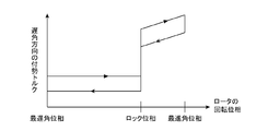
- FIG. 10 is a plan view when the rotor is in the most advanced phase in the valve timing adjustment device according to the second embodiment. 10 is a graph showing a relationship between a biasing torque in a lead angle direction by a spring and a rotation phase of a rotor in the second embodiment.
- FIG. 13 is a plan view when the rotor is at the most retarded phase in the valve timing adjustment device according to the third embodiment.
- FIG. 13 is a plan view when the rotor is in a lock phase in the valve timing adjustment device according to the third embodiment.
- FIG. 13 is a plan view when the rotor is in the most advanced phase in the valve timing adjustment device according to the third embodiment.
- FIG. 13 is a graph showing a relationship between a biasing torque in a retard direction by a spring and a rotation phase of a rotor in the third embodiment.
- FIG. 14 is a plan view when the rotor is at the most retarded phase in the valve timing adjustment device according to the fourth embodiment.
- FIG. 13 is a plan view when the rotor is in a lock phase in the valve timing adjustment device according to the fourth embodiment.
- FIG. 13 is a plan view when the rotor is at the most advanced angle phase in the valve timing adjustment device according to the fourth embodiment.
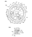
- FIG. 8A is a plan view of a valve timing adjusting device according to Embodiment 5.
- FIG. FIG. 8B is a sectional view based on the cutting line AA shown in FIG. 8A.
- FIG. 9A is a plan view of a valve timing adjusting device according to Embodiment 5.
- FIG. 9B is a cross-sectional view based on the cutting line BB shown in FIG. 9A.
- FIG. 10A is a plan view showing a modified example of the valve timing adjustment device according to Embodiment 5.
- FIG. 10B is a sectional view based on the section line CC shown in FIG. 10A.
- FIG. 15 is a diagram showing a modification of the spring according to the first to fifth embodiments.
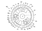
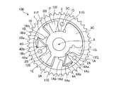
- FIG. 1A is a plan view of the valve timing adjusting apparatus 100 according to Embodiment 1 when the rotor 2 has the most retarded phase.
- FIG. 1B is a plan view of the valve timing adjusting apparatus 100 according to Embodiment 1 when the rotor 2 has the most advanced phase.
- the valve timing adjusting device 100 adjusts the opening / closing timing of at least one of an intake valve and an exhaust valve of an engine (not shown).
- the valve timing adjusting device 100 includes a case 1, a rotor 2, and springs 4A and 4B.
- the case 1 has a plurality of shoes 1A to 1C protruding toward the center of the case 1.
- a plurality of hydraulic chambers 1E to 1G are formed inside the case 1 by the plurality of shoes 1A to 1C.
- 1A and 1B show a case where the case 1 has three shoes 1A to 1C and three hydraulic chambers 1E to 1G.
- a sprocket 10 is formed on an outer peripheral surface of the case 1 to receive a driving force from a crankshaft of an engine (not shown).
- the rotor 2 is arranged in the case 1.
- the rotor 2 has a cylindrical fixing portion 2C to which a camshaft (not shown) is fixed, concave portions 2A and 2B provided on the outer peripheral surface of the fixing portion 2C, and protrudes radially outward from the outer peripheral surface of the fixing portion 2C. It has a plurality of vanes 3A to 3C. 1A and 1B show a case where the rotor 2 has three vanes 3A to 3C.
- the vanes 3A to 3C correspond one-to-one with the hydraulic chambers 1E to 1G, and partition each of the hydraulic chambers 1E to 1G into an advance hydraulic chamber and a retard hydraulic chamber.
- the hydraulic chamber 1E is partitioned by the vane 3A into an advanced hydraulic chamber 11E and a retard hydraulic chamber 12E.
- the hydraulic chamber 1F is partitioned by the vane 3B into an advanced hydraulic chamber 11F and a retard hydraulic chamber 12F
- the hydraulic chamber 1G is partitioned by the vane 3C into an advanced hydraulic chamber 11G and a retard hydraulic chamber 12G.
- the clockwise direction in the figure is the advance direction and the counterclockwise direction is the retard direction.
- the camshaft fixed to the rotor 2 is a camshaft on the intake side or the exhaust side of the engine. Further, the number of hydraulic chambers formed inside the case 1 and the number of vanes formed in the rotor 2 are not limited to those shown.
- a spring 4A is installed in a spring housing 1Aa provided in the shoe 1A of the case 1, and a spring 4B is installed in a spring housing 1Ba provided in the shoe 1B.
- the springs 4A and 4B are, for example, torsion coil springs, and have first arms 4Aa and 4Ba and second arms 4Ab and 4Bb.
- the spring storage portions 1Aa and 1Ba are circular grooves.
- the spring storage portions 1Aa and 1Ba have openings 1Ab and 1Bb for projecting the first arms 4Aa and 4Ba into the recesses 2A and 2B, and support portions 1Ac and 1Bc for supporting the second arms 4Ab and 4Bb.
- the size and position of the openings 1Ab and 1Bb in the circumferential direction are such that the first arms 4Aa and 4Ba do not contact the edges of the openings 1Ab and 1Bb regardless of the rotation phase of the rotor 2.
- the size and position of the openings 1Ab, 1Bb in the circumferential direction are such that the first arms 4Aa, 4Ba are in contact with the edges of the openings 1Ab, 1Bb only when the rotor 2 is in the most retarded phase or the most advanced phase. It may be a size and a position where it touches. Thus, the openings 1Ab and 1Bb do not hinder the circumferential movement of the first arms 4Aa and 4Ba.
- ⁇ ⁇ Recesses 2A and 2B are provided on the outer peripheral surface of the fixing portion 2C.
- the concave portion 2A is provided on the outer peripheral surface of the fixed portion 2C at a position between the vanes 3A and the vane 3C and facing the shoe 1A.
- the concave portion 2B is provided on the outer peripheral surface of the fixed portion 2C at a position between the vane 3A and the vane 3B and facing the shoe 1B.
- the circumferential size and position of the recesses 2A and 2B are always the size and position at which the first arms 4Aa and 4Ba abut against the edges of the recesses 2A and 2B regardless of the rotational phase of the rotor 2. When the first arms 4Aa and 4Ba abut against the edges of the recesses 2A and 2B, the biasing torque t1 of the springs 4A and 4B acts on the rotor 2.
- FIG. 2 is a graph showing the relationship between the urging torque in the advance direction by the springs 4A and 4B and the rotation phase of the rotor 2 in the first embodiment.
- the first arms 4Aa, 4Ba of the springs 4A, 4B are always in contact with the edges of the recesses 2A, 2B of the rotor 2 irrespective of the rotation phase of the rotor 2, and move the edges of the recesses 2A, 2B in the advance direction.
- Energize. Therefore, the urging torque t1 in the advance angle direction always acts on the rotor 2 regardless of the rotation phase. In the most retarded phase of FIG.
- the lock phase indicating the relative rotation angle at which the relative rotation between case 1 and rotor 2 is locked is the most advanced phase.
- the rotational phase of the rotor 2 quickly returns to the most advanced phase by the urging force of the springs 4A and 4B in the advanced direction. Therefore, the startability of the engine can be improved.
- the lock phase is a phase between the most retarded phase and the most advanced phase.
- the springs 4A, 4B are housed in the spring housings 1Aa, 1Ba such that the springs 4A, 4B are biased in the advance direction.
- the springs 4A and 4B may be housed in the spring housings 1Aa and 1Ba so as to be in the angular direction.
- Embodiment 3 described below shows an example in which the biasing directions of the springs 4A and 4B are in the retard direction. For example, assume that the lock phase is the most retarded phase.
- the lock phase is a phase between the most retarded phase and the most advanced phase.
- the rotational phase of the rotor 2 is quickly increased by the biasing force of the springs 4A and 4B in the retard direction. Return to lock phase. Therefore, the startability of the engine can be improved.
- the number of springs 4A and 4B may be one or three or more.
- the number of spring storage portions and the like formed inside the case 1 and the number of concave portions formed in the rotor 2 are changed according to the number of springs.
- the valve timing adjustment device 100 includes the case 1, the rotor 2, the springs 4A and 4B, and the spring housings 1Aa and 1Ba.
- the case 1 has a plurality of hydraulic chambers 1E to 1G partitioned by a plurality of shoes 1A to 1C.
- the rotor 2 includes a fixed portion 2C to which the camshaft is fixed, concave portions 2A and 2B provided on the outer peripheral surface of the fixed portion 2C, and hydraulic chambers 1E to 1G which project radially outward from the outer peripheral surface of the fixed portion 2C. Are divided into advance hydraulic chambers 11E to 11G and retard hydraulic chambers 12E to 12G, and the vanes 3A to 3C rotate relative to the case 1.
- the first arms 4Aa, 4Ba of the springs 4A, 4B abut against the edges of the recesses 2A, 2B, and the second arms 4Ab, 4Bb are supported by the supporting portions 1Ac, 1Bc of the case 1 to bias the rotor 2.
- the spring accommodating portions 1Aa and 1Ba are provided in the case 1 and have openings 1Ab and 1Bb for projecting the first arms 4Aa and 4Ba to the recesses 2A and 2B, and support the second arms 4Ab and 4Bb.
- the springs 4A and 4B are stored.
- the outer peripheral surface of the torsion coil spring can be attached to the inner peripheral surfaces of the spring housing portions 1Aa and 1Ba. Therefore, the positions of the springs 4A and 4B are stabilized, and the urging forces of the springs 4A and 4B are also stabilized.
- Embodiment 2 FIG.
- the springs 4A and 4B An example in which the range in which the urging force acts on the rotor 2 is limited to the range from the most retarded phase to the lock phase will be described.
- FIG. 3A is a plan view of the valve timing adjusting apparatus 100 according to Embodiment 2 when the rotor 2 has the most retarded phase.
- FIG. 3B is a plan view when the rotor 2 is in the lock phase in the valve timing adjustment device 100 according to the second embodiment.
- FIG. 3C is a plan view of the valve timing adjusting apparatus 100 according to Embodiment 2 when the rotor 2 is in the most advanced phase.
- 3A to 3C the same or corresponding parts as those in FIGS. 1A and 1B are denoted by the same reference numerals, and description thereof will be omitted. Note that the biasing directions of the springs 4A and 4B are advance directions, as in the first embodiment.
- the range in which the urging forces of the springs 4A and 4B act on the rotor 2 is limited to the range from the most retarded phase to the lock phase. Specifically, when the rotor 2 is in the range from the lock phase to the most advanced angle phase, the first arms 4Aa, 4Ba determine the circumferential size and position of the openings 1Ab, 1Bb by the edges of the openings 1Ab, 1Bb. And the size and position of contact.
- the openings 1Ab and 1Bb do not hinder the circumferential movement of the first arms 4Aa and 4Ba in the range from the most retarded phase to the locked phase, and the first arms 4Aa and 4Ba do not move in the range from the locked phase to the most advanced phase.
- the movement of one arm 4Aa, 4Ba in the circumferential direction is restricted. Therefore, in the range from the lock phase to the most advanced phase, the first arms 4Aa and 4Ba move away from the edges of the recesses 2A and 2B, and do not bias the rotor 2.
- FIG. 4 is a graph showing the relationship between the urging torque in the advance angle direction by the springs 4A and 4B and the rotation phase of the rotor 2 in the second embodiment.
- the first arms 4Aa and 4Ba of the springs 4A and 4B are separated from the edges of the recesses 2A and 2B formed in the rotor 2, so that the rotor 2 is advanced in the advance direction. Does not work.
- the rotational phase of the rotor 2 quickly returns to the locked phase due to the urging force of the springs 4A and 4B in the advanced direction. . Therefore, the startability of the engine can be improved.
- the first The arms 4Aa and 4Ba abut on the edges of the recesses 2A and 2B in the range from the most retarded phase to the locked phase.
- the first arms 4Aa and 4Ba separate from the edges of the recesses 2A and 2B by contacting the edges of the openings 1Ab and 1Bb in the range from the lock phase to the most advanced phase.
- Embodiment 3 In the third embodiment, in the valve timing adjustment device 100 in which the lock phase in which the relative rotation between the case 1 and the rotor 2 is locked is a phase between the most retarded phase and the most advanced phase, the spring 4A , 4B is limited to a range from the lock phase to the most advanced angle phase.
- FIG. 5A is a plan view of valve timing adjusting apparatus 100 according to Embodiment 3 when rotor 2 has the most retarded phase.
- FIG. 5B is a plan view of the valve timing adjustment device 100 according to Embodiment 3 when the rotor 2 is in the lock phase.
- FIG. 5C is a plan view of valve timing adjusting apparatus 100 according to Embodiment 3 when rotor 2 is in the most advanced phase.
- 5A to 5C the same or corresponding parts as those in FIGS. 1A, 1B, and 3A to 3C are denoted by the same reference numerals and description thereof is omitted.
- the biasing directions of the springs 4A and 4B are retard directions.
- the range in which the urging forces of the springs 4A and 4B act on the rotor 2 is limited to the range from the lock phase to the most advanced phase.
- the first arms 4Aa and 4Ba determine the circumferential size and position of the openings 1Ab and 1Bb by the edges of the openings 1Ab and 1Bb. And the size and position of contact.
- the openings 1Ab and 1Bb regulate the circumferential movement of the first arms 4Aa and 4Ba in the range from the most retarded phase to the lock phase, and the first arms 4Aa and 4Ba move in the range from the lock phase to the most advanced phase.
- the first arms 4Aa and 4Ba separate from the edges of the recesses 2A and 2B, and do not bias the rotor 2.
- FIG. 6 is a graph showing the relationship between the biasing torque in the retard direction by the springs 4A and 4B and the rotation phase of the rotor 2 in the third embodiment.
- the first arms 4Aa, 4Ba of the springs 4A, 4B are separated from the edges of the recesses 2A, 2B formed in the rotor 2, so that the rotor 2 is retarded. Does not work.
- the rotational phase of the rotor 2 quickly returns to the locked phase due to the biasing force of the springs 4A and 4B in the retard direction. . Therefore, the startability of the engine can be improved.
- the first The arms 4Aa and 4Ba separate from the edges of the recesses 2A and 2B by contacting the edges of the openings 1Ab and 1Bb in the range from the most retarded phase to the locked phase.
- the first arms 4Aa and 4Ba abut on the edges of the recesses 2A and 2B in a range from the lock phase to the most advanced phase.
- the number of springs 4A and 4B may be one or three or more.
- the number of springs is two or more and the biasing directions of all the springs are the same, the biasing force is improved. Therefore, it is possible to more quickly return the phase of the rotor 2 to the locked phase.
- Embodiment 4 In the second and third embodiments, the biasing directions of the two springs 4A and 4B are the same. On the other hand, in the fourth embodiment, the biasing directions of the two springs 4A and 4B are made opposite to each other.
- FIG. 7A is a plan view of the valve timing adjusting apparatus 100 according to Embodiment 4 when the rotor 2 has the most retarded phase.
- FIG. 7B is a plan view of the valve timing adjustment device 100 according to Embodiment 4 when the rotor 2 is in the lock phase.
- FIG. 7C is a plan view of the valve timing adjusting apparatus 100 according to Embodiment 4 when the rotor 2 has the most advanced phase.
- 7A to 7C the same or corresponding parts as those in FIGS. 1A, 1B, 3A to 3C, and 5A to 5C are denoted by the same reference numerals and description thereof is omitted.
- the biasing direction of the spring 4A is the advance direction.
- the range in which the urging force of the spring 4A acts on the rotor 2 is limited to the range from the most retarded phase to the lock phase.
- the biasing direction of the spring 4B is a retard direction.
- the range in which the biasing force of the spring 4B acts on the rotor 2 is limited to the range from the lock phase to the most advanced phase. Therefore, when the phase of the rotor 2 is between the most retarded phase and the locked phase, the rotor 2 quickly returns to the locked phase by the urging force of the spring 4A in the advanced direction. When the phase of the rotor 2 is between the lock phase and the most advanced phase, the rotor 2 quickly returns to the lock phase by the biasing force of the spring 4B in the retard direction.
- the lock phase in which the relative rotation between case 1 and rotor 2 is locked is a phase between the most retarded phase and the most advanced phase
- two springs are used.
- One of the springs 4A urges the rotor 2 in the advance direction
- the other spring 4B urges the rotor 2 in the retard direction.
- Embodiment 5 FIG. In the fifth embodiment, the position where the concave portions 2A and 2B are provided will be described.
- FIG. 8A is a plan view of a valve timing adjustment device 100 according to Embodiment 5.
- FIG. FIG. 8B is a sectional view based on the cutting line AA shown in FIG. 8A. 8A and 8B, the same or corresponding portions as those in FIGS. 1A, 1B, 3A to 3C, 5A to 5C, and 7A to 7C are denoted by the same reference numerals and description thereof is omitted.
- advance oil passages 13E to 13G and retard oil passages 14E to 14G are formed inside the fixed portion 2C of the rotor 2.
- One end of the advance oil passage 13E communicates with the advance hydraulic chamber 11E
- one end of the retard oil passage 14E communicates with the retard hydraulic chamber 12E.
- the other end of the advance oil passage 13E and the other end of the retard oil passage 14E communicate with an oil passage formed inside a camshaft (not shown).
- one ends of the advance oil passages 13F and 13G communicate with the advance hydraulic chambers 11F and 11G, respectively
- one ends of the retard oil passages 14F and 14G communicate with the retard hydraulic chambers 12F and 12G, respectively.
- the other ends of the advance oil passages 13F and 13G and the other ends of the retard oil passages 14F and 14G communicate with oil passages formed inside a camshaft (not shown).
- the engine oil is supplied to the advance hydraulic chambers 11E to 11G through the advance oil passages 13E to 13G, and the engine oil in the retard hydraulic chambers 12E to 12G is discharged through the retard oil passages 14E to 14G. As a result, the rotor 2 rotates in the advance direction.
- engine oil is supplied to the retard hydraulic chambers 12E to 12G through the retard oil passages 14E to 14G, and the engine oil in the advance hydraulic chambers 11E to 11G passes through the advance oil passages 13E to 13G. As a result, the rotor 2 rotates in the retard direction.
- the portion provided with the opening 1Ab and the concave portion 2A has a large gap and therefore does not have a function of sealing engine oil.
- FIG. 8B when the opening 1Ab and the recess 2A are provided in the entire area of the case 1 and the rotor 2 in the axis X direction, when the rotor 2 rotates in the advance direction, the advance hydraulic chamber 11E The supplied engine oil flows through the gap between the case 1 and the rotor 2 shown as the flow path R1, the opening 1Ab and the recess 2A, flows into the retard oil passage 14G, and is discharged out of the valve timing adjusting device 100. Will be.
- the engine oil supplied to the advance hydraulic chamber 11F also flows into the retard oil passage 14E through the gap between the case 1 and the rotor 2, the opening 1Bb, and the recess 2B, and the outside of the valve timing adjusting device 100. Will be discharged to
- FIG. 9A is a plan view of a valve timing adjustment device 100 according to Embodiment 5.
- FIG. FIG. 9B is a cross-sectional view based on the cutting line BB shown in FIG. 9A.
- the recesses 2A and 2B are provided at one end of the outer peripheral surface of the fixed portion 2C in the direction of the rotor rotation axis, that is, the axis X direction.
- the openings 1Ab, 1Bb are also provided at one end in the axis X direction of the tip surfaces of the shoes 1A, 1B.
- the opening 1Ab is arranged at a position facing the recess 2A
- the opening 1Bb is arranged at a position facing the recess 2B.
- the openings 1Ab, 1Bb and the recesses 2A, 2B are provided at the upper end of the paper of FIG. 9B in the direction of the axis X, but are provided at the lower end of the paper. You may be.
- the flow path R1 in FIG. 9B is smaller than the flow path R1 in FIG. 8B, and the area that functions as a seal is increased, so that the amount of oil leakage is reduced.
- FIG. 10A is a plan view showing a modification of the valve timing adjustment device 100 according to Embodiment 5.
- FIG. 10B is a sectional view based on the section line CC shown in FIG. 10A.
- the recesses 2A and 2B are provided at an intermediate position in the axis X direction on the outer peripheral surface of the fixed portion 2C.
- the openings 1Ab and 1Bb are also provided in the tip surfaces of the shoes 1A and 1B at intermediate positions in the axis X direction. That is, the opening 1Ab is arranged at a position facing the recess 2A, and the opening 1Bb is arranged at a position facing the recess 2B.
- the flow path R1 in FIG. 10B is smaller than the flow path R1 in FIG. 8B, and the area that functions as a seal is increased, so that the amount of oil leakage is reduced.
- recesses 2A and 2B are provided at one end in the axis X direction on the outer peripheral surface of fixed portion 2C, and openings 1Ab and 1Bb are formed in recesses 2A and 2B. It is preferable to be arranged at a position facing 2B. With this configuration, the amount of oil leakage can be reduced.
- the recesses 2A and 2B may be provided at an intermediate position in the direction of the axis X in the outer peripheral surface of the fixed portion 2C, and the openings 1Ab and 1Bb may be arranged at positions facing the recesses 2A and 2B. With this configuration, the amount of oil leakage can be reduced.
- the springs 4A and 4B are torsion coil springs, but the types of the springs 4A and 4B are not limited to the torsion coil springs.
- FIG. 11 is a view showing a modification of the springs 4A and 4B in the first to fifth embodiments.
- the springs 4A and 4B shown in FIG. 11 are leaf springs.
- the bent portions of the springs 4A and 4B, which are leaf springs, are supported by concave support portions 1Ad and 1Bd provided on the inner peripheral surfaces of the spring storage portions 1Aa and 1Ba.
- the first arms 4Aa, 4Ba of the springs 4A, 4B protrude from the openings 1Ab, 1Bb into the recesses 2A, 2B and come into contact with the edges of the recesses 2A, 2B. Further, the second arms 4Ab, 4Bb of the springs 4A, 4B are supported by the support portions 1Ac, 1Bc.
- the springs 4A and 4B can be housed inside the valve timing adjustment device 100, similarly to the case where they are torsion coil springs. Can provide the valve timing adjusting device 100 which does not need to secure the thickness of the springs 4A and 4B outside.
- valve timing adjusting device does not need to secure the thickness of the spring outside the case and the rotor, so that it is suitable to be used by mounting on a vehicle that requires a downsized engine. ing.
Landscapes
- Engineering & Computer Science (AREA)
- Mechanical Engineering (AREA)
- General Engineering & Computer Science (AREA)
- Valve Device For Special Equipments (AREA)
Abstract
バネ(4A,4B)は、第1の腕(4Aa,4Ba)がロータ(2)の凹部(2A,2B)の縁に当接し、第2の腕(4Ab,4Bb)がケース(1)の支持部(1Ac,1Bc)に支持されて、ロータ(2)を付勢する。バネ収納部(1Aa,1Ba)は、ケース(1)に設けられ、第1の腕(4Aa,4Ba)を凹部(2A,2B)へ突出させる開口部(1Ab,1Bb)を有し、第2の腕(4Ab,4Bb)を支持した状態でバネ(4A,4B)を収納する。
Description
この発明は、バルブの開閉タイミングを調整するバルブタイミング調整装置に関するものである。
従来の油圧駆動式バルブタイミング調整装置では、クランクシャフトと同期回転するケース及びカムシャフトと一体回転するロータの外部に、渦巻きバネ又は捩じりコイルバネ(以下、「バネ」と称する)が装着され、ロータにバネの付勢力を作用させる機構が用いられていた(例えば、特許文献1参照)。特にバルブタイミング調整装置のロック位相が最進角位置と最遅角位置との間の位相に存在し、最進角位置又は最遅角位置から上記ロック位相までの限定された範囲のみでバネの付勢力を作用させる場合、ケースとロータの外部に装着される上記バネが必須であった。
従来のバルブタイミング調整装置は、ケースとロータの外部にバネが装着される構成であるので、バネの分の厚みが増すという課題があった。
この発明は、上記のような課題を解決するためになされたもので、ケースとロータの外部にバネの分の厚みを確保する必要がないバルブタイミング調整装置を提供することを目的とする。
この発明に係るバルブタイミング調整装置は、複数のシューで仕切られた複数の油圧室を有するケースと、カムシャフトが固定される固定部、固定部の外周面に設けられた凹部、及び固定部の外周面から径方向外側へ突出して複数の油圧室それぞれを進角油圧室と遅角油圧室とに仕切る複数のベーンを有し、ケースに対して相対回転するロータと、第1の腕が凹部の縁に当接し、第2の腕がケースに支持されてロータを付勢するバネと、第1の腕を凹部へ突出させる開口部を有し、第2の腕を支持した状態でバネを収納する、ケースに設けられたバネ収納部とを備えるものである。
この発明によれば、ケースとロータの外部にバネの分の厚みを確保する必要がないバルブタイミング調整装置を提供することができる。
以下、この発明をより詳細に説明するために、この発明を実施するための形態について、添付の図面に従って説明する。
実施の形態1.
図1Aは、実施の形態1に係るバルブタイミング調整装置100においてロータ2が最遅角位相のときの平面図である。図1Bは、実施の形態1に係るバルブタイミング調整装置100においてロータ2が最進角位相のときの平面図である。バルブタイミング調整装置100は、不図示のエンジンの吸気バルブ及び排気バルブの少なくとも一方の開閉タイミングを調整するものである。バルブタイミング調整装置100は、ケース1、ロータ2、及びバネ4A,4Bを備える。
実施の形態1.
図1Aは、実施の形態1に係るバルブタイミング調整装置100においてロータ2が最遅角位相のときの平面図である。図1Bは、実施の形態1に係るバルブタイミング調整装置100においてロータ2が最進角位相のときの平面図である。バルブタイミング調整装置100は、不図示のエンジンの吸気バルブ及び排気バルブの少なくとも一方の開閉タイミングを調整するものである。バルブタイミング調整装置100は、ケース1、ロータ2、及びバネ4A,4Bを備える。
ケース1は、このケース1の中心部に向けて突出する複数のシュー1A~1Cを内部に有する。複数のシュー1A~1Cにより、ケース1の内部には、複数の油圧室1E~1Gが形成される。図1A及び図1Bは、ケース1が3つのシュー1A~1C及び3つの油圧室1E~1Gを有する場合を示している。ケース1の外周面には、不図示のエンジンのクランクシャフトからの駆動力を受けるために、スプロケット10が形成されている。
ロータ2は、ケース1内に配置される。
ロータ2は、不図示のカムシャフトが固定される円筒形状の固定部2Cと、固定部2Cの外周面に設けられた凹部2A,2Bと、固定部2Cの外周面から径方向外側へ突出する複数のベーン3A~3Cとを有する。図1A及び図1Bは、ロータ2が3つのベーン3A~3Cを有する場合を示している。ベーン3A~3Cは、油圧室1E~1Gに一対一で対応し、油圧室1E~1Gそれぞれを進角油圧室と遅角油圧室とに仕切っている。つまり、油圧室1Eは、ベーン3Aによって進角油圧室11Eと遅角油圧室12Eとに仕切られる。同様に、油圧室1Fは、ベーン3Bによって進角油圧室11Fと遅角油圧室12Fとに仕切られ、油圧室1Gは、ベーン3Cによって進角油圧室11Gと遅角油圧室12Gとに仕切られる。図示例において、ケース1に対してロータ2が相対回転する方向については、図中の時計回りの方向が進角方向、反時計回りの方向が遅角方向となる。
ロータ2は、不図示のカムシャフトが固定される円筒形状の固定部2Cと、固定部2Cの外周面に設けられた凹部2A,2Bと、固定部2Cの外周面から径方向外側へ突出する複数のベーン3A~3Cとを有する。図1A及び図1Bは、ロータ2が3つのベーン3A~3Cを有する場合を示している。ベーン3A~3Cは、油圧室1E~1Gに一対一で対応し、油圧室1E~1Gそれぞれを進角油圧室と遅角油圧室とに仕切っている。つまり、油圧室1Eは、ベーン3Aによって進角油圧室11Eと遅角油圧室12Eとに仕切られる。同様に、油圧室1Fは、ベーン3Bによって進角油圧室11Fと遅角油圧室12Fとに仕切られ、油圧室1Gは、ベーン3Cによって進角油圧室11Gと遅角油圧室12Gとに仕切られる。図示例において、ケース1に対してロータ2が相対回転する方向については、図中の時計回りの方向が進角方向、反時計回りの方向が遅角方向となる。
固定部2Cに固定された不図示のカムシャフトと、ロータ2とは、一体的に回転する。図1A及び図1B中の軸Xは、ロータ2がカムシャフトと一体的に回転するときの回転軸であるロータ回転軸を示している。ケース1も、軸Xを回転軸として回転するように配置されている。なお、ロータ2は、カムシャフトと一体的に回転する一方、油圧を受けることでケース1に対して相対回転する。
ロータ2に固定されるカムシャフトは、エンジンの吸気側又は排気側のカムシャフトである。また、ケース1の内部に形成される油圧室の数及びロータ2に形成されるベーンの数は、図示のものに限らない。
ケース1のシュー1Aに設けられたバネ収納部1Aaにバネ4Aが設置され、シュー1Bに設けられたバネ収納部1Baにバネ4Bが設置されている。バネ4A,4Bは、例えば捩じりコイルバネであり、第1の腕4Aa,4Baと第2の腕4Ab,4Bbとを有する。バネ4A,4Bが捩じりコイルバネである場合、バネ収納部1Aa,1Baは円形状の溝である。この円形状の溝の内周面にバネ4A,4Bの外周面を添わせることで、バネ4A,4Bの位置が安定し、バネ4A,4Bの付勢力も安定する。これらのバネ4A,4Bは、進角方向の付勢トルクt1を発生させる。
バネ収納部1Aa,1Baは、第1の腕4Aa,4Baを凹部2A,2Bへ突出させる開口部1Ab,1Bbと、第2の腕4Ab,4Bbを支持する支持部1Ac,1Bcとを有する。開口部1Ab,1Bbの周方向の大きさ及び位置は、ロータ2の回転位相によらず、第1の腕4Aa,4Baが開口部1Ab,1Bbの縁に当接しない大きさ及び位置とする。なお、開口部1Ab,1Bbの周方向の大きさ及び位置は、ロータ2が最遅角位相又は最進角位相のときのみ、第1の腕4Aa,4Baが開口部1Ab,1Bbの縁に当接する大きさ及び位置であってもよい。このように、開口部1Ab,1Bbは、第1の腕4Aa,4Baの周方向の移動を妨げない。
固定部2Cの外周面には、凹部2A,2Bが設けられる。凹部2Aは、固定部2Cの外周面における、ベーン3Aとベーン3Cとの間かつシュー1Aに対向する位置に設けられる。凹部2Bは、固定部2Cの外周面における、ベーン3Aとベーン3Bとの間かつシュー1Bに対向する位置に設けられる。凹部2A,2Bの周方向の大きさ及び位置は、ロータ2の回転位相によらず、常に、第1の腕4Aa,4Baが凹部2A,2Bの縁に当接する大きさ及び位置とする。第1の腕4Aa,4Baが凹部2A,2Bの縁に当接することにより、バネ4A,4Bの付勢トルクt1がロータ2に作用する。
図2は、実施の形態1において、バネ4A,4Bによる進角方向の付勢トルクとロータ2の回転位相との関係を示すグラフである。バネ4A,4Bの第1の腕4Aa,4Baは、ロータ2の回転位相によらず常にロータ2の凹部2A,2Bの縁に当接した状態で、凹部2A,2Bの縁を進角方向に付勢する。そのため、ロータ2には、回転位相によらず常に進角方向の付勢トルクt1が作用する。なお、図1Aの最遅角位相において、バネ4A,4Bのねじりモーメントが相対的に大きいため、相対的に大きな付勢トルクt1が生じる。一方、図1Bの最進角位相において、バネ4A,4Bのねじりモーメントが相対的に小さいため、相対的に小さな付勢トルクt1が生じる。
なお、図2において、ロータ2が最進角位相から最遅角位相の方向へ回転する場合と、最遅角位相から最進角位相の方向へ回転する場合とで付勢トルクに差が生じている。この差が生じる理由は、ロータ2が回転するときに発生する摺動抵抗(又は摩擦抵抗とも言う)によるヒステリシスである。ロータ2が最進角位相から最遅角位相の方向へ回転するときには進角方向の摩擦抵抗が発生するため、バルブタイミング調整装置100全体として見た際の進角方向の付勢トルクは「バネ4A,4Bのトルク+摩擦抵抗」となる。一方、ロータ2が最遅角位相から最進角位相の方向へ回転するときには遅角方向の摩擦抵抗が発生するため、バルブタイミング調整装置100全体として見た際の進角方向の付勢トルクは「バネ4A,4Bのトルク-摩擦抵抗」となる。そのため、ロータ2が最進角位相から最遅角位相の方向へ回転する場合と、最遅角位相から最進角位相の方向へ回転する場合とでは、摩擦抵抗の分だけ付勢トルクに差が生じる。
実施の形態2以降においても、同様に、摩擦抵抗の分だけ付勢トルクに差が生じる。
実施の形態2以降においても、同様に、摩擦抵抗の分だけ付勢トルクに差が生じる。
例えば、ケース1とロータ2との相対回転がロックされる相対回転角度を示すロック位相が最進角位相である場合を想定する。この想定例において、ロータ2の位相が最進角位相にない場合にエンジンが始動すると、バネ4A,4Bの進角方向の付勢力によってロータ2の回転位相が素早く最進角位相へ戻る。したがって、エンジンの始動性を高めることが可能となる。
あるいは、ロック位相が最遅角位相と最進角位相との間の位相である場合を想定する。この想定例において、ロータ2の位相が最遅角位相からロック位相までの間の位相である場合にエンジンが始動すると、バネ4A,4Bの進角方向の付勢力によってロータ2の回転位相が素早くロック位相へ戻る。したがって、エンジンの始動性を高めることが可能となる。
ケース1とロータ2との相対回転をロックするための機構には、周知の技術を用いればよいため、図1A及び図1Bでは図示を省略する。
あるいは、ロック位相が最遅角位相と最進角位相との間の位相である場合を想定する。この想定例において、ロータ2の位相が最遅角位相からロック位相までの間の位相である場合にエンジンが始動すると、バネ4A,4Bの進角方向の付勢力によってロータ2の回転位相が素早くロック位相へ戻る。したがって、エンジンの始動性を高めることが可能となる。
ケース1とロータ2との相対回転をロックするための機構には、周知の技術を用いればよいため、図1A及び図1Bでは図示を省略する。
なお、上記例では、バネ4A,4Bの付勢方向が進角方向になるように、バネ4A,4Bがバネ収納部1Aa,1Baに収納されたが、バネ4A,4Bの付勢方向が遅角方向になるように、バネ4A,4Bがバネ収納部1Aa,1Baに収納されてもよい。後述する実施の形態3に、バネ4A,4Bの付勢方向が遅角方向である場合の例を示す。
例えば、ロック位相が最遅角位相である場合を想定する。この想定例において、ロータ2の位相が最遅角位相にない場合にエンジンが始動すると、バネ4A,4Bの遅角方向の付勢力によってロータ2の回転位相が素早く最遅角位相へ戻る。したがって、エンジンの始動性を高めることが可能となる。
あるいは、ロック位相が最遅角位相と最進角位相との間の位相である場合を想定する。この想定例において、ロータ2の位相が最進角位相からロック位相までの間の位相である場合にエンジンが始動すると、バネ4A,4Bの遅角方向の付勢力によってロータ2の回転位相が素早くロック位相へと戻る。したがって、エンジンの始動性を高めることが可能となる。
例えば、ロック位相が最遅角位相である場合を想定する。この想定例において、ロータ2の位相が最遅角位相にない場合にエンジンが始動すると、バネ4A,4Bの遅角方向の付勢力によってロータ2の回転位相が素早く最遅角位相へ戻る。したがって、エンジンの始動性を高めることが可能となる。
あるいは、ロック位相が最遅角位相と最進角位相との間の位相である場合を想定する。この想定例において、ロータ2の位相が最進角位相からロック位相までの間の位相である場合にエンジンが始動すると、バネ4A,4Bの遅角方向の付勢力によってロータ2の回転位相が素早くロック位相へと戻る。したがって、エンジンの始動性を高めることが可能となる。
また、バネ4A,4Bの数は、1つ又は3つ以上であってもよい。ケース1の内部に形成されるバネ収納部等の数及びロータ2に形成される凹部の数は、バネの数に応じて変更される。
以上のように、実施の形態1に係るバルブタイミング調整装置100は、ケース1と、ロータ2と、バネ4A,4Bと、バネ収納部1Aa,1Baとを備える。ケース1は、複数のシュー1A~1Cで仕切られた複数の油圧室1E~1Gを有する。ロータ2は、カムシャフトが固定される固定部2Cと、固定部2Cの外周面に設けられた凹部2A,2Bと、固定部2Cの外周面から径方向外側へ突出して油圧室1E~1Gそれぞれを進角油圧室11E~11Gと遅角油圧室12E~12Gとに仕切る複数のベーン3A~3Cとを有し、ケース1に対して相対回転する。バネ4A,4Bは、第1の腕4Aa,4Baが凹部2A,2Bの縁に当接し、第2の腕4Ab,4Bbがケース1の支持部1Ac,1Bcに支持されてロータ2を付勢する。バネ収納部1Aa,1Baは、ケース1に設けられ、第1の腕4Aa,4Baを凹部2A,2Bへ突出させる開口部1Ab,1Bbを有し、第2の腕4Ab,4Bbを支持した状態でバネ4A,4Bを収納する。この構成によれば、バルブタイミング調整装置100の内部にバネ4A,4Bを収納できるため、ケース1とロータ2の外部にバネ4A,4Bの分の厚みを確保する必要がないバルブタイミング調整装置100を提供することができる。したがって、エンジンの小型化が可能となる。
また、バネ4A,4Bに捩じりコイルバネを用いることにより、バネ収納部1Aa,1Baの内周面に捩じりコイルバネの外周面を添わせることができる。したがって、バネ4A,4Bの位置が安定し、バネ4A,4Bの付勢力も安定する。
実施の形態2.
実施の形態2では、ケース1とロータ2との相対回転がロックされるロック位相が、最遅角位相と最進角位相との間の位相であるバルブタイミング調整装置100において、バネ4A,4Bの付勢力がロータ2に作用する範囲を、最遅角位相からロック位相までの範囲に限定する例について説明する。
実施の形態2では、ケース1とロータ2との相対回転がロックされるロック位相が、最遅角位相と最進角位相との間の位相であるバルブタイミング調整装置100において、バネ4A,4Bの付勢力がロータ2に作用する範囲を、最遅角位相からロック位相までの範囲に限定する例について説明する。
図3Aは、実施の形態2に係るバルブタイミング調整装置100においてロータ2が最遅角位相のときの平面図である。図3Bは、実施の形態2に係るバルブタイミング調整装置100においてロータ2がロック位相のときの平面図である。図3Cは、実施の形態2に係るバルブタイミング調整装置100においてロータ2が最進角位相のときの平面図である。図3A~図3Cにおいて、図1A及び図1Bと同一又は相当する部分は、同一の符号を付し説明を省略する。なお、バネ4A,4Bの付勢方向は、実施の形態1と同様に、進角方向である。
実施の形態2では、バネ4A,4Bの付勢力がロータ2に作用する範囲を、最遅角位相からロック位相までの範囲に限定する。具体的には、開口部1Ab,1Bbの周方向の大きさ及び位置を、ロータ2がロック位相から最進角位相までの範囲のとき第1の腕4Aa,4Baが開口部1Ab,1Bbの縁に当接する大きさ及び位置とする。この構成により、開口部1Ab,1Bbは、最遅角位相からロック位相までの範囲において第1の腕4Aa,4Baの周方向の移動を妨げず、ロック位相から最進角位相までの範囲において第1の腕4Aa,4Baの周方向の移動を規制する。したがって、ロック位相から最進角位相までの範囲において、第1の腕4Aa,4Baが凹部2A,2Bの縁から離れ、ロータ2を付勢しない。
図4は、実施の形態2において、バネ4A,4Bによる進角方向の付勢トルクとロータ2の回転位相との関係を示すグラフである。ロック位相から最進角位相までの範囲において、バネ4A,4Bが有する第1の腕4Aa,4Baが、ロータ2に形成された凹部2A,2Bの縁から離れるため、ロータ2には進角方向の付勢トルクが作用しない。ロータ2の位相が最遅角位相からロック位相までの間の位相である場合にエンジンが始動すると、バネ4A,4Bの進角方向の付勢力によってロータ2の回転位相が素早くロック位相へと戻る。したがって、エンジンの始動性を高めることが可能となる。
以上のように、実施の形態2によれば、ケース1とロータ2との相対回転がロックされるロック位相が最遅角位相と最進角位相との間の位相である場合、第1の腕4Aa,4Baは、最遅角位相からロック位相までの範囲において凹部2A,2Bの縁に当接する。一方、第1の腕4Aa,4Baは、ロック位相から最進角位相までの範囲において、開口部1Ab,1Bbの縁に当接することによって凹部2A,2Bの縁から離れる。この構成により、バネ4A,4Bの付勢力がロータ2に作用する範囲を、最遅角位相からロック位相までの範囲に限定することができる。また、この構成においてバネ4A,4Bの付勢方向が進角方向である場合、ロータ2の位相を素早くロック位相へ戻すことが可能となる。
実施の形態3.
実施の形態3では、ケース1とロータ2との相対回転がロックされるロック位相が、最遅角位相と最進角位相との間の位相である場合のバルブタイミング調整装置100において、バネ4A,4Bの付勢力がロータ2に作用する範囲を、ロック位相から最進角位相までの範囲に限定する例について説明する。
実施の形態3では、ケース1とロータ2との相対回転がロックされるロック位相が、最遅角位相と最進角位相との間の位相である場合のバルブタイミング調整装置100において、バネ4A,4Bの付勢力がロータ2に作用する範囲を、ロック位相から最進角位相までの範囲に限定する例について説明する。
図5Aは、実施の形態3に係るバルブタイミング調整装置100におけるロータ2が最遅角位相のときの平面図である。図5Bは、実施の形態3に係るバルブタイミング調整装置100におけるロータ2がロック位相のときの平面図である。図5Cは、実施の形態3に係るバルブタイミング調整装置100におけるロータ2が最進角位相のときの平面図である。図5A~図5Cにおいて、図1A、図1B及び図3A~図3Cと同一又は相当する部分は、同一の符号を付し説明を省略する。なお、バネ4A,4Bの付勢方向は、遅角方向である。
実施の形態3では、バネ4A,4Bの付勢力がロータ2に作用する範囲を、ロック位相から最進角位相までの範囲に限定する。具体的には、開口部1Ab,1Bbの周方向の大きさ及び位置を、ロータ2がロック位相から最遅角位相までの範囲のとき第1の腕4Aa,4Baが開口部1Ab,1Bbの縁に当接する大きさ及び位置とする。この構成により、開口部1Ab,1Bbは、最遅角位相からロック位相までの範囲において第1の腕4Aa,4Baの周方向の移動を規制し、ロック位相から最進角位相までの範囲において第1の腕4Aa,4Baの周方向の移動を妨げない。したがって、最遅角位相からロック位相までの範囲において、第1の腕4Aa,4Baが凹部2A,2Bの縁から離れ、ロータ2を付勢しない。
図6は、実施の形態3において、バネ4A,4Bによる遅角方向の付勢トルクとロータ2の回転位相との関係を示すグラフである。最遅角位相からロック位相までの範囲において、バネ4A,4Bが有する第1の腕4Aa,4Baが、ロータ2に形成された凹部2A,2Bの縁から離れるため、ロータ2には遅角方向の付勢トルクが作用しない。ロータ2の位相が最進角位相からロック位相までの間の位相である場合にエンジンが始動すると、バネ4A,4Bの遅角方向の付勢力によってロータ2の回転位相が素早くロック位相へと戻る。したがって、エンジンの始動性を高めることが可能となる。
以上のように、実施の形態3によれば、ケース1とロータ2との相対回転がロックされるロック位相が最遅角位相と最進角位相との間の位相である場合、第1の腕4Aa,4Baは、最遅角位相からロック位相までの範囲において開口部1Ab,1Bbの縁に当接することによって凹部2A,2Bの縁から離れる。一方、第1の腕4Aa,4Baは、ロック位相から最進角位相までの範囲において凹部2A,2Bの縁に当接する。この構成により、バネ4A,4Bの付勢力がロータ2に作用する範囲を、ロック位相から最進角位相までの範囲に限定することができる。また、この構成においてバネ4A,4Bの付勢方向が遅角方向である場合、ロータ2の位相を素早くロック位相へ戻すことが可能となる。
なお、実施の形態2及び実施の形態3において、バネ4A,4Bの数は、1つ又は3つ以上でもよい。バネの数を2つ以上にし、かつ、全てのバネの付勢方向を同一方向にした場合、付勢力が向上する。そのため、ロータ2の位相をより素早くロック位相へ戻すことが可能となる。
実施の形態4.
上記実施の形態2及び実施の形態3では、2つのバネ4A,4Bの付勢方向が同一方向であった。これに対し、実施の形態4では、2つのバネ4A,4Bの付勢方向を互いに逆方向にする。
上記実施の形態2及び実施の形態3では、2つのバネ4A,4Bの付勢方向が同一方向であった。これに対し、実施の形態4では、2つのバネ4A,4Bの付勢方向を互いに逆方向にする。
図7Aは、実施の形態4に係るバルブタイミング調整装置100におけるロータ2が最遅角位相のときの平面図である。図7Bは、実施の形態4に係るバルブタイミング調整装置100におけるロータ2がロック位相のときの平面図である。図7Cは、実施の形態4に係るバルブタイミング調整装置100におけるロータ2が最進角位相のときの平面図である。図7A~図7Cにおいて、図1A、図1B、図3A~図3C、及び図5A~図5Cと同一又は相当する部分は、同一の符号を付し説明を省略する。
実施の形態4において、バネ4Aの付勢方向は、進角方向である。また、このバネ4Aの付勢力がロータ2に作用する範囲は、最遅角位相からロック位相までの範囲に限定されている。これに対し、バネ4Bの付勢方向は、遅角方向である。また、このバネ4Bの付勢力がロータ2に作用する範囲は、ロック位相から最進角位相までの範囲に限定されている。したがって、ロータ2の位相が最遅角位相とロック位相との間にある場合、バネ4Aの進角方向の付勢力によってロータ2が素早くロック位相へ戻る。ロータ2の位相がロック位相と最進角位相との間にある場合、バネ4Bの遅角方向の付勢力によってロータ2が素早くロック位相へ戻る。
以上のように、実施の形態4によれば、ケース1とロータ2との相対回転がロックされるロック位相が最遅角位相と最進角位相との間の位相である場合、2つのバネ4A,4Bのうちの一方のバネ4Aはロータ2を進角方向に付勢し、他方のバネ4Bはロータ2を遅角方向に付勢する。この構成により、ロータ2がどの位相にあったとしても、素早くロック位相へ戻すことが可能となる。
実施の形態5.
実施の形態5では、凹部2A,2Bが設けられる位置について説明する。
実施の形態5では、凹部2A,2Bが設けられる位置について説明する。
図8Aは、実施の形態5に係るバルブタイミング調整装置100の平面図である。図8Bは、図8Aに示す切断線A-Aに基づく断面図である。図8A及び図8Bにおいて、図1A、図1B、図3A~図3C、図5A~図5C、及び図7A~図7Cと同一又は相当する部分は、同一の符号を付し説明を省略する。
図8Aに示すように、ロータ2の固定部2Cの内部には、進角油路13E~13Gと遅角油路14E~14Gとが形成されている。進角油路13Eの一端は進角油圧室11Eに連通し、遅角油路14Eの一端は遅角油圧室12Eに連通する。進角油路13Eの他端及び遅角油路14Eの他端は、不図示のカムシャフト内部に形成された油路に連通する。同様に、進角油路13F,13Gの一端は、それぞれ進角油圧室11F,11Gに連通し、遅角油路14F,14Gの一端は、それぞれ遅角油圧室12F,12Gに連通する。また、進角油路13F,13Gの他端及び遅角油路14F,14Gの他端は、不図示のカムシャフト内部に形成された油路に連通する。
エンジンオイルが進角油路13E~13Gを通って進角油圧室11E~11Gへ供給されると共に、遅角油圧室12E~12Gのエンジンオイルが遅角油路14E~14Gを通って排出されることにより、ロータ2が進角方向に回転する。これに対し、エンジンオイルが遅角油路14E~14Gを通って遅角油圧室12E~12Gへ供給されると共に、進角油圧室11E~11Gのエンジンオイルが進角油路13E~13Gを通って排出されることにより、ロータ2が遅角方向に回転する。
シュー1Aの先端面と固定部2Cの外周面とが対向する部分のうち、開口部1Ab及び凹部2Aが設けられた部分は、隙間が大きいため、エンジンオイルをシールする機能を有さない。図8Bに示すように、開口部1Ab及び凹部2Aが、ケース1及びロータ2において軸X方向の全域に設けられている場合、ロータ2が進角方向へ回転するとき、進角油圧室11Eに供給されたエンジンオイルが、流路R1として示すケース1とロータ2との隙間、開口部1Ab及び凹部2Aを通って、遅角油路14Gに流れ込み、バルブタイミング調整装置100の外へ排出されることになる。同様に、進角油圧室11Fに供給されたエンジンオイルも、ケース1とロータ2との隙間、開口部1Bb及び凹部2Bを通って、遅角油路14Eに流れ込み、バルブタイミング調整装置100の外へ排出されることになる。
そこで、実施の形態5では、流路R1を通って漏れるオイル量を削減するために好ましい構成例について説明する。
図9Aは、実施の形態5に係るバルブタイミング調整装置100の平面図である。図9Bは、図9Aに示す切断線B-Bに基づく断面図である。図9A及び図9Bの例では、凹部2A,2Bは、固定部2Cの外周面のうち、ロータ回転軸方向、つまり軸X方向の一方の端部に設けられる。開口部1Ab,1Bbも、シュー1A,1Bの先端面のうち、軸X方向の一方の端部に設けられる。つまり、開口部1Abは凹部2Aに対向する位置に配置され、開口部1Bbは凹部2Bに対向する位置に配置される。なお、図9A及び図9Bでは、軸X方向のうち、図9Bの紙面上側の端部に開口部1Ab,1Bbと凹部2A,2Bとが設けられているが、紙面下側の端部に設けられてもよい。この構成により、図9B中の流路R1が、図8B中の流路R1に比べて小さくなり、シールとして機能する面積が大きくなるため、オイル漏れ量が削減される。
図9Aは、実施の形態5に係るバルブタイミング調整装置100の平面図である。図9Bは、図9Aに示す切断線B-Bに基づく断面図である。図9A及び図9Bの例では、凹部2A,2Bは、固定部2Cの外周面のうち、ロータ回転軸方向、つまり軸X方向の一方の端部に設けられる。開口部1Ab,1Bbも、シュー1A,1Bの先端面のうち、軸X方向の一方の端部に設けられる。つまり、開口部1Abは凹部2Aに対向する位置に配置され、開口部1Bbは凹部2Bに対向する位置に配置される。なお、図9A及び図9Bでは、軸X方向のうち、図9Bの紙面上側の端部に開口部1Ab,1Bbと凹部2A,2Bとが設けられているが、紙面下側の端部に設けられてもよい。この構成により、図9B中の流路R1が、図8B中の流路R1に比べて小さくなり、シールとして機能する面積が大きくなるため、オイル漏れ量が削減される。
図10Aは、実施の形態5に係るバルブタイミング調整装置100の変形例を示す平面図である。図10Bは、図10Aに示す切断線C-Cに基づく断面図である。図10A及び図10Bの例では、凹部2A,2Bは、固定部2Cの外周面のうち、軸X方向の途中位置に設けられる。開口部1Ab,1Bbも、シュー1A,1Bの先端面のうち、軸X方向の途中位置に設けられる。つまり、開口部1Abは凹部2Aに対向する位置に配置され、開口部1Bbは凹部2Bに対向する位置に配置される。この構成により、図10B中の流路R1が、図8B中の流路R1に比べて小さくなり、シールとして機能する面積が大きくなるため、オイル漏れ量が削減される。
以上のように、実施の形態5によれば、凹部2A,2Bは、固定部2Cの外周面のうち、軸X方向の一方の端部に設けられ、開口部1Ab,1Bbは、凹部2A,2Bに対向する位置に配置されていることが好ましい。この構成により、オイル漏れ量の削減が可能となる。
また、凹部2A,2Bは、固定部2Cの外周面のうち、軸X方向の途中位置に設けられ、開口部1Ab,1Bbは、凹部2A,2Bに対向する位置に配置されてもよい。この構成によっても、オイル漏れ量の削減が可能となる。
なお、実施の形態1~5では、バネ4A,4Bが捩じりコイルバネであったが、バネ4A,4Bの種類は、捩じりコイルバネに限らない。
図11は、実施の形態1~5におけるバネ4A,4Bの変形例を示す図である。図11に示すバネ4A,4Bは、板バネである。板バネであるバネ4A,4Bの折れ曲がった部分は、バネ収納部1Aa,1Baの内周面に設けられた凹状の支持部1Ad,1Bdによって支持される。バネ4A,4Bの第1の腕4Aa,4Baは、開口部1Ab,1Bbから凹部2A,2Bへ突出し、凹部2A,2Bの縁に当接する。また、バネ4A,4Bの第2の腕4Ab,4Bbは、支持部1Ac,1Bcによって支持される。
このように、バネ4A,4Bが、板バネ又は渦巻きバネ等である場合にも、捩じりコイルバネである場合と同様に、バルブタイミング調整装置100の内部に収納できるため、ケース1とロータ2の外部にバネ4A,4Bの分の厚みを確保する必要がないバルブタイミング調整装置100を提供することができる。
図11は、実施の形態1~5におけるバネ4A,4Bの変形例を示す図である。図11に示すバネ4A,4Bは、板バネである。板バネであるバネ4A,4Bの折れ曲がった部分は、バネ収納部1Aa,1Baの内周面に設けられた凹状の支持部1Ad,1Bdによって支持される。バネ4A,4Bの第1の腕4Aa,4Baは、開口部1Ab,1Bbから凹部2A,2Bへ突出し、凹部2A,2Bの縁に当接する。また、バネ4A,4Bの第2の腕4Ab,4Bbは、支持部1Ac,1Bcによって支持される。
このように、バネ4A,4Bが、板バネ又は渦巻きバネ等である場合にも、捩じりコイルバネである場合と同様に、バルブタイミング調整装置100の内部に収納できるため、ケース1とロータ2の外部にバネ4A,4Bの分の厚みを確保する必要がないバルブタイミング調整装置100を提供することができる。
また、本願発明はその発明の範囲内において、実施の形態の任意の構成要素の変形、もしくは実施の形態の任意の構成要素の省略が可能である。
以上のように、この発明に係るバルブタイミング調整装置は、ケースとロータの外部にバネの分の厚みを確保する必要がないので、エンジンの小型化が求められる車両に搭載して用いるのに適している。
1 ケース、1A~1C シュー、1Aa,1Ba バネ収納部、1Ab,1Bb 開口部、1Ac,1Bc,1Ad,1Bd 支持部、1E~1G 油圧室、2 ロータ、2A,2B 凹部、2C 固定部、3A~3C ベーン、4A,4B バネ、4Aa,4Ba 第1の腕、4Ab,4Bb 第2の腕、10 スプロケット、11E~11G 進角油圧室、12E~12G 遅角油圧室、13E~13G 進角油路、14E~14G 遅角油路、100 バルブタイミング調整装置。
Claims (9)
- 複数のシューで仕切られた複数の油圧室を有するケースと、
カムシャフトが固定される固定部、前記固定部の外周面に設けられた凹部、及び前記固定部の外周面から径方向外側へ突出して前記複数の油圧室それぞれを進角油圧室と遅角油圧室とに仕切る複数のベーンを有し、前記ケースに対して相対回転するロータと、
第1の腕が前記凹部の縁に当接し、第2の腕が前記ケースに支持されて前記ロータを付勢するバネと、
前記第1の腕を前記凹部へ突出させる開口部を有し、前記第2の腕を支持した状態で前記バネを収納する、前記ケースに設けられたバネ収納部とを備えるバルブタイミング調整装置。 - 前記バネは、捩じりコイルバネであることを特徴とする請求項1記載のバルブタイミング調整装置。
- 前記ケースと前記ロータとの相対回転がロックされるロック位相が、最遅角位相と最進角位相との間の位相である場合、
前記第1の腕は、前記最遅角位相から前記ロック位相までの範囲において前記凹部の縁に当接し、前記ロック位相から前記最進角位相までの範囲において前記開口部の縁に当接することによって前記凹部の縁から離れることを特徴とする請求項1記載のバルブタイミング調整装置。 - 前記ケースと前記ロータとの相対回転がロックされるロック位相が、最遅角位相と最進角位相との間の位相である場合、
前記第1の腕は、前記最遅角位相から前記ロック位相までの範囲において前記開口部の縁に当接することによって前記凹部の縁から離れ、前記ロック位相から前記最進角位相までの範囲において前記凹部の縁に当接することを特徴とする請求項1記載のバルブタイミング調整装置。 - 前記バネは、2つ設けられていることを特徴とする請求項3又は請求項4記載のバルブタイミング調整装置。
- 2つの前記バネは、前記ロータを同じ方向に付勢することを特徴とする請求項5記載のバルブタイミング調整装置。
- 前記2つのバネの一方は、前記ロータを進角方向に付勢し、他方は前記ロータを遅角方向に付勢することを特徴とする請求項5記載のバルブタイミング調整装置。
- 前記凹部は、前記固定部の外周面のうち、ロータ回転軸方向の一方の端部に設けられ、
前記開口部は、前記凹部に対向する位置に配置されていることを特徴とする請求項1記載のバルブタイミング調整装置。 - 前記凹部は、前記固定部の外周面のうち、ロータ回転軸方向の途中位置に設けられ、
前記開口部は、前記凹部に対向する位置に配置されていることを特徴とする請求項1記載のバルブタイミング調整装置。
Priority Applications (2)
| Application Number | Priority Date | Filing Date | Title |
|---|---|---|---|
| JP2020540917A JP6779423B2 (ja) | 2018-09-05 | 2018-09-05 | バルブタイミング調整装置 |
| PCT/JP2018/032863 WO2020049653A1 (ja) | 2018-09-05 | 2018-09-05 | バルブタイミング調整装置 |
Applications Claiming Priority (1)
| Application Number | Priority Date | Filing Date | Title |
|---|---|---|---|
| PCT/JP2018/032863 WO2020049653A1 (ja) | 2018-09-05 | 2018-09-05 | バルブタイミング調整装置 |
Publications (1)
| Publication Number | Publication Date |
|---|---|
| WO2020049653A1 true WO2020049653A1 (ja) | 2020-03-12 |
Family
ID=69723091
Family Applications (1)
| Application Number | Title | Priority Date | Filing Date |
|---|---|---|---|
| PCT/JP2018/032863 Ceased WO2020049653A1 (ja) | 2018-09-05 | 2018-09-05 | バルブタイミング調整装置 |
Country Status (2)
| Country | Link |
|---|---|
| JP (1) | JP6779423B2 (ja) |
| WO (1) | WO2020049653A1 (ja) |
Citations (5)
| Publication number | Priority date | Publication date | Assignee | Title |
|---|---|---|---|---|
| JPH11210421A (ja) * | 1998-01-23 | 1999-08-03 | Mitsubishi Motors Corp | カム位相可変装置 |
| US20070245991A1 (en) * | 2006-02-02 | 2007-10-25 | Schaeffler Kg | Hydraulic camshaft adjuster |
| JP2011069316A (ja) * | 2009-09-28 | 2011-04-07 | Aisin Seiki Co Ltd | 弁開閉時期制御装置 |
| DE102013222826A1 (de) * | 2013-11-11 | 2015-05-13 | Schaeffler Technologies AG & Co. KG | Nockenwellenversteller |
| JP2018109373A (ja) * | 2016-12-28 | 2018-07-12 | 株式会社ミクニ | バルブタイミング変更装置 |
-
2018
- 2018-09-05 WO PCT/JP2018/032863 patent/WO2020049653A1/ja not_active Ceased
- 2018-09-05 JP JP2020540917A patent/JP6779423B2/ja not_active Expired - Fee Related
Patent Citations (5)
| Publication number | Priority date | Publication date | Assignee | Title |
|---|---|---|---|---|
| JPH11210421A (ja) * | 1998-01-23 | 1999-08-03 | Mitsubishi Motors Corp | カム位相可変装置 |
| US20070245991A1 (en) * | 2006-02-02 | 2007-10-25 | Schaeffler Kg | Hydraulic camshaft adjuster |
| JP2011069316A (ja) * | 2009-09-28 | 2011-04-07 | Aisin Seiki Co Ltd | 弁開閉時期制御装置 |
| DE102013222826A1 (de) * | 2013-11-11 | 2015-05-13 | Schaeffler Technologies AG & Co. KG | Nockenwellenversteller |
| JP2018109373A (ja) * | 2016-12-28 | 2018-07-12 | 株式会社ミクニ | バルブタイミング変更装置 |
Also Published As
| Publication number | Publication date |
|---|---|
| JP6779423B2 (ja) | 2020-11-04 |
| JPWO2020049653A1 (ja) | 2020-12-17 |
Similar Documents
| Publication | Publication Date | Title |
|---|---|---|
| US8056519B2 (en) | Camshaft phaser intermediate locking pin and seat | |
| WO2020196404A1 (ja) | 作動油制御弁およびバルブタイミング調整装置 | |
| US7878164B2 (en) | Apparatus for preventing leakage across rotor vanes in a vane-type camshaft phaser | |
| CN103210188B (zh) | 阀开闭定时控制装置 | |
| WO2020049653A1 (ja) | バルブタイミング調整装置 | |
| JP4288220B2 (ja) | 内燃機関のバルブタイミング制御装置 | |
| US7013856B2 (en) | Valve timing control device | |
| KR102322288B1 (ko) | 원웨이 클러치 방식 가변밸브타이밍 기구 및 엔진 시스템 | |
| JPH11182216A (ja) | 内燃機関のバルブタイミング制御装置 | |
| JP5900533B2 (ja) | バルブタイミング調整装置 | |
| WO2001029377A1 (fr) | Dispositif d'ajustement a reglage de distribution | |
| US7066122B2 (en) | Variable valve timing controller | |
| JP2009209719A (ja) | バルブタイミング調整装置 | |
| JP2007023953A (ja) | バルブタイミング調整装置 | |
| JP2006299891A (ja) | 駆動力伝達装置およびそれを用いた内燃機関用バルブタイミング調整装置 | |
| JP2005344586A (ja) | バルブタイミング調整装置 | |
| JP4327047B2 (ja) | バルブタイミング調整装置 | |
| JP2003120230A (ja) | バルブタイミング調整装置 | |
| WO2016185918A1 (ja) | 内燃機関のバルブタイミング制御装置 | |
| CN105745403B (zh) | 内燃机的气门正时控制装置 | |
| JP6786021B2 (ja) | バルブタイミング調整装置 | |
| WO2018220789A1 (ja) | バルブタイミング調整装置 | |
| JP2020076383A (ja) | 内燃機関のバルブタイミング制御装置 | |
| JP2009138685A (ja) | バルブタイミング調整装置 | |
| WO2020059016A1 (ja) | バルブタイミング調整装置 |
Legal Events
| Date | Code | Title | Description |
|---|---|---|---|
| 121 | Ep: the epo has been informed by wipo that ep was designated in this application |
Ref document number: 18932481 Country of ref document: EP Kind code of ref document: A1 |
|
| ENP | Entry into the national phase |
Ref document number: 2020540917 Country of ref document: JP Kind code of ref document: A |
|
| NENP | Non-entry into the national phase |
Ref country code: DE |
|
| 122 | Ep: pct application non-entry in european phase |
Ref document number: 18932481 Country of ref document: EP Kind code of ref document: A1 |