WO2020045282A1 - 光接続部品 - Google Patents
光接続部品 Download PDFInfo
- Publication number
- WO2020045282A1 WO2020045282A1 PCT/JP2019/033052 JP2019033052W WO2020045282A1 WO 2020045282 A1 WO2020045282 A1 WO 2020045282A1 JP 2019033052 W JP2019033052 W JP 2019033052W WO 2020045282 A1 WO2020045282 A1 WO 2020045282A1
- Authority
- WO
- WIPO (PCT)
- Prior art keywords
- fixing member
- optical fiber
- positioning
- peripheral wall
- optical
- Prior art date
- Legal status (The legal status is an assumption and is not a legal conclusion. Google has not performed a legal analysis and makes no representation as to the accuracy of the status listed.)
- Ceased
Links
Images






Classifications
-
- G—PHYSICS
- G02—OPTICS
- G02B—OPTICAL ELEMENTS, SYSTEMS OR APPARATUS
- G02B6/00—Light guides; Structural details of arrangements comprising light guides and other optical elements, e.g. couplings
- G02B6/24—Coupling light guides
- G02B6/42—Coupling light guides with opto-electronic elements
- G02B6/4201—Packages, e.g. shape, construction, internal or external details
- G02B6/4219—Mechanical fixtures for holding or positioning the elements relative to each other in the couplings; Alignment methods for the elements, e.g. measuring or observing methods especially used therefor
- G02B6/4236—Fixing or mounting methods of the aligned elements
- G02B6/424—Mounting of the optical light guide
-
- G—PHYSICS
- G02—OPTICS
- G02B—OPTICAL ELEMENTS, SYSTEMS OR APPARATUS
- G02B6/00—Light guides; Structural details of arrangements comprising light guides and other optical elements, e.g. couplings
- G02B6/24—Coupling light guides
- G02B6/42—Coupling light guides with opto-electronic elements
- G02B6/4201—Packages, e.g. shape, construction, internal or external details
- G02B6/4219—Mechanical fixtures for holding or positioning the elements relative to each other in the couplings; Alignment methods for the elements, e.g. measuring or observing methods especially used therefor
- G02B6/4236—Fixing or mounting methods of the aligned elements
- G02B6/4239—Adhesive bonding; Encapsulation with polymer material
-
- G—PHYSICS
- G02—OPTICS
- G02B—OPTICAL ELEMENTS, SYSTEMS OR APPARATUS
- G02B6/00—Light guides; Structural details of arrangements comprising light guides and other optical elements, e.g. couplings
- G02B6/24—Coupling light guides
- G02B6/42—Coupling light guides with opto-electronic elements
- G02B6/4201—Packages, e.g. shape, construction, internal or external details
- G02B6/4219—Mechanical fixtures for holding or positioning the elements relative to each other in the couplings; Alignment methods for the elements, e.g. measuring or observing methods especially used therefor
- G02B6/4236—Fixing or mounting methods of the aligned elements
- G02B6/424—Mounting of the optical light guide
- G02B6/4243—Mounting of the optical light guide into a groove
-
- G—PHYSICS
- G02—OPTICS
- G02B—OPTICAL ELEMENTS, SYSTEMS OR APPARATUS
- G02B6/00—Light guides; Structural details of arrangements comprising light guides and other optical elements, e.g. couplings
- G02B6/44—Mechanical structures for providing tensile strength and external protection for fibres, e.g. optical transmission cables
- G02B6/4439—Auxiliary devices
- G02B6/4471—Terminating devices ; Cable clamps
- G02B6/4478—Bending relief means
Definitions
- Patent Document 1 discloses an optical connector in which an optical fiber is curved by making a curved hole in a connector main body and inserting and fixing an optical fiber in the hole.
- the optical connection component has an optical fiber, a first fixing member that fixes one end of the optical fiber, and a curvature along which the optical fiber is adhered to the optical fiber with an adhesive.
- a second fixing member having one or both of an outer peripheral wall and an inner peripheral wall and a positioning portion for positioning the first fixing member at one end.
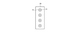
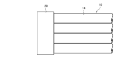
- FIG. 1 is a front view illustrating an example of an optical fiber core included in an optical connection component according to the present disclosure. It is a side view which shows the optical fiber core wire of FIG. 1A.
- FIG. 3 is a front view illustrating an example of a first fixing member included in the optical connection component of the present disclosure in a state where an optical fiber is fixed.
- FIG. 2B is a plan view showing the first fixing member of FIG. 2A with the optical fiber fixed.
- FIG. 13 is a front view showing another example of the first fixing member included in the optical connection component of the present disclosure in a state where an optical fiber is fixed. It is a top view which shows the 1st fixing member of FIG. 2C in the state which fixed the optical fiber.
- FIG. 3 is a front view illustrating an example of an optical fiber core included in an optical connection component according to the present disclosure. It is a side view which shows the optical fiber core wire of FIG. 1A.
- FIG. 3 is a front view illustrating an example of a first fixing member included
- FIG. 4 is a perspective view illustrating an example of a second fixing member included in the optical connection component of the present disclosure. It is a side view of the 2nd fixing member shown in Drawing 3A. It is a figure which shows the example which attached the 1st fixing member to the 2nd fixing member shown in FIG. 3A.
- FIG. 13 is a perspective view illustrating another example of the second fixing member included in the optical connection component of the present disclosure.
- FIG. 4B is a side view of the second fixing member shown in FIG. 4A. It is a figure which shows the example which attached the 1st fixing member to the 2nd fixing member shown in FIG. 4A.
- the optical connector disclosed in Patent Literature 1 when an optical fiber whose coating is removed is inserted into a curved hole, the optical fiber may be disconnected.
- the present disclosure provides an optical connection component that can be easily assembled to bend an optical fiber without requiring a connector member having a curved hole.
- An optical connection component includes an optical fiber, a first fixing member that fixes one end of the optical fiber, and the optical fiber adhered to the optical fiber with an adhesive.
- a second fixing member having one or both of an outer peripheral wall and an inner peripheral wall having a curvature and a positioning portion for positioning the first fixing member at one end.
- the optical fiber can be used without the need for a connector member having a curved hole. It is possible to obtain an optical connection component that can be easily assembled for bending.
- the second fixing member includes a side wall on which one or both of the outer peripheral wall and the inner peripheral wall vertically protrudes, and the second fixing member sandwiches one or both of the outer peripheral wall and the inner peripheral wall. It is preferable to have an open surface on the side opposite to the side wall. According to this configuration, it is easy to mount the first fixing member on which the optical fiber is mounted to the second fixing member, and the possibility of damage when bending the optical fiber is reduced.
- the positioning portion has a tapered surface connected to the vertical positioning surface in addition to a positioning surface parallel to the optical fiber and a vertical positioning surface at the one end. According to this configuration, when the first fixing member to which the optical fiber is attached is attached to the second fixing member, the portion of the optical fiber coming out of the first fixing member is damaged by touching the positioning portion of the second fixing member. There is no fear.
- the first fixing member may have a hole penetrating the optical fiber, and (5) the first fixing member may include two plates that sandwich one end of the optical fiber. May be included. According to this configuration, the first fixing member can be selected from a plurality of configurations.
- (First embodiment) 1A and 1B are a front view and a side view, respectively, illustrating an example of an optical fiber included in the optical connection component of the present disclosure.
- 2A and 2B are a front view and a side view, respectively, showing an example of a first fixing member included in the optical connection component of the present disclosure in a state where an optical fiber is fixed.
- the optical fiber 10 has at least one core 11 made of silica glass, a clad 12 provided around the core 11 and having a lower refractive index than the core 11, and a resin coating layer 14 surrounding the clad 12. are doing.
- the glass core 11 and the clad 12 constitute a glass fiber 13.
- the first fixing member 20 is a member for aligning the optical fibers 10, and is a substantially rectangular parallelepiped glass capillary member having pores 21.
- the inner diameter of the fine hole 21 is slightly larger than the outer diameter of the glass fiber 13, and when the glass fiber 13 is inserted into the fine hole 21, the glass fiber 13 is loosely fitted and positioned so as to be able to move back and forth. Then, the first fixing member 20 and the glass fiber 13 are filled with an adhesive in the gap between the fine hole 21 and the glass fiber 13 by utilizing the capillary phenomenon, and both are fixed.
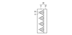
- FIGS. 2C and 2D are a front view and a side view showing another example of the first fixing member included in the optical connection component of the present disclosure, in which the optical fiber is fixed, in which the optical fiber is fixed.
- the first fixing member 30 includes a V-groove substrate 31 made of glass and a flat substrate 32 also made of glass.
- the V-groove substrate 31 has, for example, four V-grooves 33 arranged in parallel, and each V-groove 33 is large enough to mount the glass fiber 13 thereon.
- the flat substrate 32 has a size that covers the V-grooves 33 of the V-groove substrate 31 and is flat.
- the glass fiber 13 is placed on each V-groove 33 of the V-groove substrate 31, and is covered with a flat substrate 32.
- the flat substrate 32 is fixed to the V-groove substrate 31 together with the glass fiber 13 with an adhesive.
- the first fixing member 30 including the V-groove substrate 31 and the flat substrate 32 has a substantially rectangular parallelepiped shape.
- the optical fiber 10 fixed to the first fixing members 20 and 30 may be one or a plurality other than four, and an optical fiber obtained by tapering a plurality of optical fibers 10 arranged in parallel with a common coating. It may be a tape ribbon.
- the optical fiber 10 may have a single core or a plurality of cores.
- the ends of the first fixing members 20 and 30 to which the optical fiber 10 is fixed are polished together with the glass fiber 13 and fixed to an optical element mounting substrate (not shown) by, for example, an adhesive.
- the material of the first fixing members 20 and 30 is preferably glass from the viewpoint of matching the thermal expansion coefficient with that of the glass fiber 13, but may be resin.
- the term “optical fiber” means a glass fiber provided with a coating layer, and includes a part in which the coating layer is removed and the glass fiber is exposed.
- the first fixing members 20 and 30 are provided at one end of the optical fiber 10, but the first fixing members 20 and 30 are attached to the other end of the optical fiber 10 and May be polished.
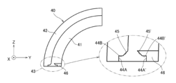
- FIG. 3A is a perspective view showing an example 40 of the second fixing member included in the optical connection component of the present disclosure
- FIG. 3B is a side view of the second fixing member 40
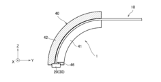
- FIG. 3C is a diagram illustrating an example in which the first fixing member is attached to the second fixing member 40.
- the second fixing member 40 is a member for bending the optical fiber 10, and the first fixing member 20 (or the first fixing member 30) to which the optical fiber 10 is fixed at one end side may be used.
- the fixing member 20 will be described as an example.
- the optical fiber 10 is bent along the inner peripheral surface of the outer peripheral wall 42 provided on the second fixing member 40.
- the second fixing member 40 has a side wall 41 having an arc shape on the YZ plane, and an outer peripheral wall 42 having an arc shape protruding vertically (X-axis direction) from the side wall 41. I have.
- the thickness of the outer peripheral wall 42 in the X-axis direction is such that the optical fiber 10 does not come off when the first fixing member 20 described later is mounted.
- One end of the second fixing member 40 has a positioning portion 43 for positioning the first fixing member 20.
- the positioning portion 43 includes a positioning projection 46 protruding from one end of the side wall 41 of the second fixing member 40, and an end of the outer peripheral wall 42 facing the positioning projection 46. More specifically, the positioning portion 43 includes a positioning surface 44A parallel to the XZ plane at the end of the outer peripheral wall 42, a positioning surface 44B parallel to the XY plane, and a positioning surface 44A ′ parallel to the XZ plane of the positioning projection 46. And a positioning surface 44B ′ parallel to the XY plane, and a side wall 41.
- the distance between the positioning surface 44A of the outer peripheral wall 42 and the positioning surface 44A 'of the positioning projection 46 is equal to the width of two surfaces of the first fixing member 20 parallel to the parallel surface of the optical fibers 10.
- the positioning surfaces 44A and 44A 'parallel to the XZ plane are positioning surfaces parallel to the optical fiber 10
- the positioning surfaces 44B and 44B' parallel to the XY plane are positioning surfaces perpendicular to the optical fiber 10. .
- the second fixing member 40 has an open surface on the side opposite to the side wall 41 with the wall surface of the outer peripheral wall 42 interposed therebetween. For this reason, when positioning the first fixing member 20 to which the optical fiber 10 is fixed to the positioning portion 43 of the second fixing member 40, the parallel surface of the optical fiber 10 fixed to the first fixing member 20 is parallel to the XZ plane. And the first fixing member 20 is inserted into the positioning portion 43 of the second fixing member 40 from the open surface side (the positive side in the X-axis direction). Then, the first fixing member 20 is inserted until it comes into contact with the side wall 41.
- the two surfaces of the rectangular parallelepiped first fixing member 20 parallel to the parallel surfaces of the optical fibers 10 are positioned by the positioning surface 44A of the outer peripheral wall 42 and the positioning surface 44A 'of the positioning projection 46.
- the surface of the first fixing member 20 into which the optical fiber 10 is inserted is positioned on the positioning surface 44B of the outer peripheral wall 42 and the positioning surface 44B 'of the positioning projection 46.
- one surface of the first fixing member 20 perpendicular to the parallel surface of the optical fibers 10 is positioned by the side wall 41. At that time, as shown in FIG. 3C, the optical fiber 10 is bent along the inner peripheral surface of the outer peripheral wall 42.
- the first fixing member 20 and the positioning portion 43, and the optical fiber 10 and the inner peripheral surface of the outer peripheral wall 42 are fixed using an adhesive (not shown) to obtain the optical connection component 1.
- the adhesive can be supplied from the open surface side of the second fixing member 40.
- the material of the second fixing member 40 may be glass, metal, or resin as long as the outer peripheral wall 42 and the positioning portion 43 can be integrally formed by cutting, molding, or the like. Further, as shown in FIG. 3B, it is desirable that the positioning surface 44B of the outer peripheral wall 42 and the positioning surface 44B 'of the positioning projection 46 have tapered surfaces 45 and 45', respectively. Thereby, when the first fixing member 20 is positioned on the second fixing member 40 and the optical fiber 10 is bent, the first fixing member 20 is displaced from the positioning portion 43, and the coating layer 14 of the optical fiber 10 and its The internal glass fiber 13 can be prevented from being damaged by contact with the positioning portion 43.
- the tapered surfaces 45, 45 ' are connected to positioning surfaces 44B, 44B' perpendicular to the optical fiber 10, respectively.
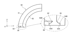
- FIG. 4A is a perspective view showing another example 50 of the second fixing member included in the optical connection component of the present disclosure
- FIG. 4B is a side view of the second fixing member 50
- FIG. 4C is a diagram illustrating an example in which the first fixing member is attached to the second fixing member 50.
- the second fixing member 50 is a member for bending the optical fiber 10, and the first fixing member 20 (or the first fixing member 30) to which the optical fiber 10 is fixed is positioned at one end thereof. Is bent along the outer peripheral surface of the inner peripheral wall 52 provided on the second fixing member 50.
- the second fixing member 50 has an arc-shaped side wall 51 on the YZ plane and an arc-shaped inner peripheral wall 52 protruding from the side wall 51 in the vertical direction (X-axis direction). .
- the thickness of the inner peripheral wall 52 in the X-axis direction is a thickness on which the optical fiber 10 can be placed when the first fixing member 20 described later is mounted.
- One end of the second fixing member 50 has a positioning portion 53 for positioning the first fixing member 20.
- the positioning portion 53 includes a positioning projection 56 protruding from one end of the side wall 51 of the second fixing member 50, and an end of the inner peripheral wall 52 facing the positioning projection 56. More specifically, the positioning portion 53 includes a positioning surface 54A parallel to the XZ plane at the end of the inner peripheral wall 52, a positioning surface 54B parallel to the XY plane, and a positioning surface 54A ′ of the positioning projection 56 parallel to the XZ plane. And a positioning surface 54B ′ parallel to the XY plane, and a side wall 51.
- the distance between the positioning surface 54A of the inner peripheral wall 52 and the positioning surface 54A 'of the positioning projection 56 is equal to the width of two surfaces of the first fixing member 20 parallel to the parallel surfaces of the optical fibers 10.
- the positioning surfaces 54A, 54A 'parallel to the XZ plane are positioning surfaces parallel to the optical fiber 10
- the positioning surfaces 54B, 54B' parallel to the XY plane are positioning surfaces perpendicular to the optical fiber 10. .
- the second fixing member 50 has an open surface on the side opposite to the side wall 41 with the wall surface of the inner peripheral wall 52 interposed therebetween. For this reason, when positioning the first fixing member 20 to which the optical fiber 10 is fixed to the positioning portion 53 of the second fixing member 50, the parallel surface of the optical fiber 10 fixed to the first fixing member 20 is parallel to the XZ plane. And the first fixing member 20 is inserted into the positioning portion 53 of the second fixing member 50 from the open surface side (the positive side in the X-axis direction). Then, the first fixing member 20 is inserted until it contacts the side wall 51.
- the two surfaces of the rectangular parallelepiped first fixing member 20 parallel to the parallel surfaces of the optical fibers 10 are positioned by the positioning surface 54A of the inner peripheral wall 52 and the positioning surface 54A 'of the positioning projection 56.
- the surface of the first fixing member 20 into which the optical fiber 10 is inserted is positioned on the positioning surface 54B of the inner peripheral wall 52 and the positioning surface 54B 'of the positioning projection 56.
- one surface of the first fixing member 20 perpendicular to the parallel surface of the optical fibers 10 is positioned by the side wall 51.
- the first fixing member 20 and the positioning portion 53 are first fixed by the adhesive.
- the optical fiber 10 is bent along the outer peripheral surface of the inner peripheral wall 52.
- the optical fiber 10 is fixed to the outer peripheral surface of the inner peripheral wall 52 using an adhesive, whereby the optical connection component 1 is obtained.
- the supply of the adhesive can be performed using the open surface of the second fixing member 50.
- the material of the second fixing member 50 is glass, metal, or the like, as long as the inner peripheral wall 52 and the positioning portion 53 can be integrally formed by cutting, molding, or the like. Any of resins may be used. Further, as shown in FIG. 4B, it is desirable that the positioning surface 54B of the inner peripheral wall 52 and the positioning surface 54B 'of the positioning projection 56 have tapered surfaces 55 and 55', respectively. As a result, when the first fixing member 20 is positioned on the second fixing member 50 and the optical fiber 10 is bent, the first fixing member 20 is displaced from the positioning portion 53 and comes into contact with the positioning portion 53 to be damaged. Can be prevented.
- the tapered surfaces 55, 55 ' are connected to positioning surfaces 54B, 54B' perpendicular to the optical fiber 10, respectively.
- the second fixing member has both the outer peripheral wall and the inner peripheral wall.
- the structure has an outer peripheral wall 42 of the second fixing member 40 in the first embodiment and an inner peripheral wall 52 of the second fixing member 50 in the second embodiment.
- the end portions of the outer peripheral wall and the inner peripheral wall have positioning portions for positioning the first fixing member 20.
- the gap may be made approximately the same size as the diameter of the optical fiber 10, and the optical fiber 10 may be sandwiched between the outer peripheral wall and the inner peripheral wall.
- the gap may be made larger than the diameter of the optical fiber, and an adhesive may be filled from the open surface to fix the optical fiber 10 in the gap between the outer peripheral wall and the inner peripheral wall.
- the positioning portion is formed integrally with the end of the outer peripheral wall or the inner peripheral wall, but may be provided separately from the outer peripheral wall or the inner peripheral wall.
- Optical connection parts 10 ... optical fiber, 11 ... core, 12 ... clad, 13 ... glass fiber, 14 ... Coating layer, 20, 30 ... first fixing member, 21 ... pores, 31 ... V-groove substrate, 32 ... flat board, 33 ... V groove, 40 ... second fixing member, 41 ... side wall, 42 ... outer peripheral wall, 43 ... Positioning part, 44A, 44A ', 44B, 44B' ... positioning surfaces, 45, 45 '... tapered surface, 46 ... Positioning projection, 50 ... second fixing member, 51 ... side wall, 52 ... inner peripheral wall, 53 ... Positioning part, 54A, 54A ', 54B, 54B' ... positioning surfaces, 55, 55 '... tapered surface, 56 ... Positioning protrusions.
Landscapes
- Physics & Mathematics (AREA)
- General Physics & Mathematics (AREA)
- Optics & Photonics (AREA)
- Mechanical Coupling Of Light Guides (AREA)
- Light Guides In General And Applications Therefor (AREA)
- Optical Couplings Of Light Guides (AREA)
Abstract
光接続部品1は、光ファイバ10と、光ファイバ10の一端部を固定する第一固定部材20(30)と、前記光ファイバ10と接着剤で接着された、前記光ファイバ10が沿う曲率を有する外周壁42および内周壁のどちらか一方または両方と一端に前記第一固定部材20(30)を位置決めする位置決め部とを有する第二固定部材40と、を備える。
Description
本開示は、光接続部品に関する。本願は、2018年8月27日に出願された日本特許出願第2018-158779号による優先権を主張するものであり、その内容に依拠すると共に、その全体を参照して本明細書に組み込む。
光モジュールの小型化に伴い、発光素子、受光素子、および光回路のような光素子を搭載した基板に、光ファイバの一端を垂直に対向接続する際、光ファイバの基板からの高さを低く抑えるよう光接続部品の低背化が求められている。光接続部品の低背化のためには、光ファイバの先端部付近を小半径で屈曲させることが必要となる。このため、特許文献1には、コネクタ本体に湾曲する孔をあけ、この孔に光ファイバを挿通固定することによって、光ファイバを湾曲させた光コネクタが開示されている。
本開示の一態様に係る光接続部品は、光ファイバと、前記光ファイバの一端部を固定する第一固定部材と、前記光ファイバと接着剤で接着された、前記光ファイバが沿う曲率を有する外周壁および内周壁のどちらか一方または両方と一端に前記第一固定部材を位置決めする位置決め部とを有する第二固定部材と、を備えている。
[本開示が解決しようとする課題]
特許文献1に開示された光コネクタは、湾曲した孔に被覆を除去した光ファイバを挿通する際に、光ファイバが断線するおそれがあった。本開示は、湾曲した孔を有するコネクタ部材を必要とせずに、光ファイバを屈曲させるために組み立て操作が容易な光接続部品を提供する。
特許文献1に開示された光コネクタは、湾曲した孔に被覆を除去した光ファイバを挿通する際に、光ファイバが断線するおそれがあった。本開示は、湾曲した孔を有するコネクタ部材を必要とせずに、光ファイバを屈曲させるために組み立て操作が容易な光接続部品を提供する。
[本開示の実施形態の説明]
最初に本開示の実施形態を列記して説明する。
(1)本開示の一態様に係る光接続部品は、光ファイバと、前記光ファイバの一端部を固定する第一固定部材と、前記光ファイバと接着剤で接着された、前記光ファイバが沿う曲率を有する外周壁および内周壁のどちらか一方または両方と一端に前記第一固定部材を位置決めする位置決め部とを有する第二固定部材と、を備えている。
最初に本開示の実施形態を列記して説明する。
(1)本開示の一態様に係る光接続部品は、光ファイバと、前記光ファイバの一端部を固定する第一固定部材と、前記光ファイバと接着剤で接着された、前記光ファイバが沿う曲率を有する外周壁および内周壁のどちらか一方または両方と一端に前記第一固定部材を位置決めする位置決め部とを有する第二固定部材と、を備えている。
この構成によれば、光ファイバを第二固定部材の外周壁および内周壁のどちらか一方または両方に沿わせて接着することにより、湾曲した孔を有するコネクタ部材を必要とせずに、光ファイバを屈曲させるための組み立て操作が容易な光接続部品を得ることができる。
(2)前記第二固定部材が、前記外周壁および内周壁のどちらか一方または両方が垂直に突出する側壁を含み、前記外周壁および前記内周壁のどちらか一方または両方の壁面を挟んで前記側壁と反対側に、開放面を有していることが好ましい。この構成によれば、光ファイバを装着した第一固定部材を第二固定部材に装着することが容易となり、光ファイバを曲げる際に損傷するおそれが小さくなる。
(3)前記位置決め部が、前記一端部における前記光ファイバと平行な位置決め面、垂直な位置決め面に加えて、前記垂直な位置決め面と接続するテーパ面を有することが望ましい。この構成によれば、光ファイバを装着した第一固定部材を第二固定部材に装着する際に、第一固定部材から出た部分の光ファイバが第二固定部材の位置決め部に触れて損傷するおそれがなくなる。
(4)前記第一固定部材が、前記光ファイバを貫通する孔を有していてもよく、また、(5)前記第一固定部材が、前記光ファイバの一端部を挟持する2枚の板状部材を含んでいてもよい。この構成によれば、第一の固定部材として、複数の構成から選択可能となる。
[本開示の実施形態の詳細]
以下、図面を参照しながら、本開示の光接続部品に係る好適な実施形態について説明する。以下の説明において、異なる図面においても同じ符号を付した構成は同様のものであるとして、その説明を省略する場合がある。なお、本発明はこれらの実施形態での例示に限定されるものではなく、請求の範囲に記載された事項の範囲内および均等の範囲内におけるすべての変更を含む。また、複数の実施形態について組み合わせが可能である限り、本発明は任意の実施形態を組み合わせたものを含む。
以下、図面を参照しながら、本開示の光接続部品に係る好適な実施形態について説明する。以下の説明において、異なる図面においても同じ符号を付した構成は同様のものであるとして、その説明を省略する場合がある。なお、本発明はこれらの実施形態での例示に限定されるものではなく、請求の範囲に記載された事項の範囲内および均等の範囲内におけるすべての変更を含む。また、複数の実施形態について組み合わせが可能である限り、本発明は任意の実施形態を組み合わせたものを含む。
(第1の実施形態)
図1Aおよび図1Bは、それぞれ本開示の光接続部品が含む光ファイバの一例を示す正面図および側面図である。また、図2Aおよび図2Bは、それぞれ本開示の光接続部品が含む第一固定部材の一例を、光ファイバを固定した状態で示す正面図および側面図である。光ファイバ10は、石英系ガラスからなる少なくとも1つのコア11と、コア11の周囲に設けたコア11よりも屈折率の低いクラッド12と、クラッド12の周囲を覆う樹脂製の被覆層14を有している。ガラス製のコア11とクラッド12は、ガラスファイバ13を構成している。
図1Aおよび図1Bは、それぞれ本開示の光接続部品が含む光ファイバの一例を示す正面図および側面図である。また、図2Aおよび図2Bは、それぞれ本開示の光接続部品が含む第一固定部材の一例を、光ファイバを固定した状態で示す正面図および側面図である。光ファイバ10は、石英系ガラスからなる少なくとも1つのコア11と、コア11の周囲に設けたコア11よりも屈折率の低いクラッド12と、クラッド12の周囲を覆う樹脂製の被覆層14を有している。ガラス製のコア11とクラッド12は、ガラスファイバ13を構成している。
図2A、図2Bに示すように、例えば、4本の光ファイバ10の一端部が、第一固定部材20に固定される。本実施形態では、図1Bに示すように光ファイバ10の一端部の被覆層14が除去されて、ガラスファイバ13のクラッド12が露出され、この露出したガラスファイバ13が第一固定部材20に固定される。第一固定部材20は、光ファイバ10を整列させるための部材であり、細孔21を有するほぼ直方体形状のガラス製のキャピラリ部材である。細孔21の内径はガラスファイバ13の外径よりもわずかに大きく、ガラスファイバ13を細孔21内に挿通した際に、ガラスファイバ13は遊嵌されて前後に移動可能に位置決めされる。そして、第一固定部材20とガラスファイバ13とは、毛細管現象を利用して細孔21とガラスファイバ13との間隙に接着剤が充填され、両者が固定される。
図2Cおよび図2Dは、それぞれ光ファイバを固定した、本開示の光接続部品が含む第一固定部材の他の例を、光ファイバを固定した状態で示す正面図および側面図である。第一固定部材30は、ガラス製のV溝基板31と、同じくガラス製の平基板32からなる。V溝基板31には、例えば、平行に並んだ4本のV溝33を有し、各V溝33は、ガラスファイバ13が載置可能な大きさである。平基板32は、V溝基板31の各V溝33を覆う大きさで平面状である。ガラスファイバ13をV溝基板31の各V溝33に載置し、平基板32で蓋をする。そして、平基板32はガラスファイバ13とともにV溝基板31に接着剤で固定される。V溝基板31と平基板32とからなる第一固定部材30は、第一固定部材20と同様に、ほぼ直方体の形状を有する。
第一固定部材20、30に固定される光ファイバ10は、1本でも、4本以外の複数本でもよく、平行に配列された複数本の光ファイバ10を共通の被覆でテープ化した光ファイバテープ心線であってもよい。また、光ファイバ10は、単一のコアあるいは複数コアを有するものであってよい。光ファイバ10を固定した第一固定部材20、30は、先端がガラスファイバ13とともに研磨され、図示しない光素子搭載基板に対して例えば接着剤によって固着される。なお、第一固定部材20,30の材質は、ガラスファイバ13と熱膨張係数を合わせる点からは、ガラスが好適であるが樹脂であってもよい。
また、光ファイバ10を第一固定部材20、30に固定する際に、ガラスファイバ13を露出させて、第一固定部材20、30に固定しているが、被覆層14を設けた状態で固定してもよい。このため、本開示において、「光ファイバ」の語は、ガラスファイバに被覆層を設けたものを意味するが、その一部において被覆層が除去されガラスファイバが露出したものを含む。なお、本実施形態では、光ファイバ10の一端側に第一固定部材20、30を設けているが、光ファイバ10の他端側にも上述の第一固定部材20、30を取り付け、先端部を研磨しておいてもよい。
図3Aは、本開示の光接続部品が含む第二固定部材の一例40を示す斜視図であり、図3Bは、第二固定部材40の側面図である。また、図3Cは、第二固定部材40に第一固定部材を装着した例を示す図である。第二固定部材40は、光ファイバ10を屈曲させるための部材であり、その一端側に、光ファイバ10を固定した第一固定部材20(または、第一固定部材30でもよい。以下、第一固定部材20を例に説明する。)が位置決めされ、光ファイバ10は第二固定部材40に設けた外周壁42の内周面に沿って曲げられている。
第二固定部材40は、図3Aに示すように、YZ平面で円弧形状である側壁41と、この側壁41から垂直方向(X軸方向)に突出した円弧形状の外周壁42とを有している。外周壁42のX軸方向の厚さは、後述する第一固定部材20を装着した際に、光ファイバ10が外れない厚さである。第二固定部材40の一端には、第一固定部材20を位置決めするための位置決め部43を有する。
本実施形態では、位置決め部43は、第二固定部材40の側壁41の一端部から突出した位置決め用突起46と、この位置決め用突起46に対向する外周壁42の端部を含む。より具体的には、位置決め部43は、外周壁42の端部のXZ平面に平行な位置決め面44AとXY平面に平行な位置決め面44B、位置決め用突起46のXZ平面に平行な位置決め面44A’とXY平面に平行な位置決め面44B’、および、側壁41とを含む。外周壁42の位置決め面44Aと位置決め用突起46の位置決め面44A’の間隔は、第一固定部材20の光ファイバ10の並列面に平行な2面の幅に等しい。ここで、XZ平面に平行な位置決め面44A、44A‘は、光ファイバ10と平行な位置決め面であり、XY平面に平行な位置決め面44B、44B’は、光ファイバ10と垂直な位置決め面である。
第二固定部材40は、外周壁42の壁面を挟んで側壁41と反対側に開放面を有している。このため、第二固定部材40の位置決め部43に、光ファイバ10を固定した第一固定部材20を位置決めする際は、第一固定部材20に固定した光ファイバ10の並列面がXZ平面に平行になるように第一固定部材20を位置合わせし、開放面側(X軸方向正側)から第一固定部材20を第二固定部材40の位置決め部43に挿入する。そして、第一固定部材20が側壁41に当接するまで挿入する。
これによって、直方体形状の第一固定部材20の光ファイバ10の並列面に平行な2面は、外周壁42の位置決め面44Aと位置決め用突起46の位置決め面44A’によって位置決めされる。また、第一固定部材20の光ファイバ10が挿入されている面は、外周壁42の位置決め面44Bと位置決め用突起46の位置決め面44B’に位置決めされる。さらに、第一固定部材20の光ファイバ10の並列面に垂直な1面は、側壁41によって位置決めされる。その際、図3Cに示すように、光ファイバ10は外周壁42の内周面に沿って屈曲される。この状態で、第一固定部材20と位置決め部43、および、光ファイバ10と外周壁42の内周面とを図示しない接着剤を用いて固定し、光接続部品1を得る。接着剤の供給は、第二固定部材40の開放面側から供給することができる。
第二固定部材40の材質は、切削、モールド成型などによって外周壁42や位置決め部43を一体に成形可能であれば、ガラス、金属、樹脂のいずれであっても構わない。また、図3Bに示すように、外周壁42の位置決め面44Bと位置決め用突起46の位置決め面44B’それぞれがテーパ面45、45’を有することが望ましい。これにより、第一固定部材20を第二固定部材40に位置決めして、光ファイバ10を屈曲させる際に、第一固定部材20が位置決め部43からずれて、光ファイバ10の被覆層14およびその内部のガラスファイバ13が位置決め部43と接触して傷つくのを防止することができる。テーパ面45、45’は、それぞれ光ファイバ10と垂直な位置決め面44B、44B’と接続されている。
(第2の実施形態)
図4Aは、本開示の光接続部品が含む第二固定部材の他の例50を示す斜視図であり、図4Bは、第二固定部材50の側面図である。また、図4Cは、第二固定部材50に第一固定部材を装着した例を示す図である。第二固定部材50は、光ファイバ10を屈曲させるための部材であり、その一端側に、光ファイバ10を固定した第一固定部材20(または第一固定部材30)が位置決めされ、光ファイバ10は第二固定部材50に設けた内周壁52の外周面に沿って曲げられている。
図4Aは、本開示の光接続部品が含む第二固定部材の他の例50を示す斜視図であり、図4Bは、第二固定部材50の側面図である。また、図4Cは、第二固定部材50に第一固定部材を装着した例を示す図である。第二固定部材50は、光ファイバ10を屈曲させるための部材であり、その一端側に、光ファイバ10を固定した第一固定部材20(または第一固定部材30)が位置決めされ、光ファイバ10は第二固定部材50に設けた内周壁52の外周面に沿って曲げられている。
第二固定部材50は、図4Aに示すように、YZ平面で円弧形状の側壁51と、この側壁51から垂直方向(X軸方向)に突出した円弧形状の内周壁52とを有している。内周壁52のX軸方向の厚さは、後述する第一固定部材20を装着した際に、光ファイバ10が載置可能な厚さである。第二固定部材50の一端には、第一固定部材20を位置決めするための位置決め部53を有する。
本実施形態では、位置決め部53は、第二固定部材50の側壁51の一端部から突出した位置決め用突起56と、この位置決め用突起56に対向する内周壁52の端部を含む。より具体的には、位置決め部53は、内周壁52の端部のXZ平面に平行な位置決め面54AとXY平面に平行な位置決め面54B、位置決め用突起56のXZ平面に平行な位置決め面54A’とXY平面に平行な位置決め面54B’、および、側壁51とを含む。内周壁52の位置決め面54Aと位置決め用突起56の位置決め面54A’の間隔は、第一固定部材20の光ファイバ10の並列面に平行な2面の幅に等しい。ここで、XZ平面に平行な位置決め面54A、54A‘は、光ファイバ10と平行な位置決め面であり、XY平面に平行な位置決め面54B、54B’は、光ファイバ10と垂直な位置決め面である。
第二固定部材50は、内周壁52の壁面を挟んで側壁41と反対側に開放面を有している。このため、第二固定部材50の位置決め部53に、光ファイバ10を固定した第一固定部材20を位置決めする際は、第一固定部材20に固定した光ファイバ10の並列面がXZ平面に平行になるように第一固定部材20を位置合わせし、開放面側(X軸方向正側)から第一固定部材20を第二固定部材50の位置決め部53に挿入する。そして、第一固定部材20が側壁51に当接するまで挿入する。
これによって、直方体形状の第一固定部材20の光ファイバ10の並列面に平行な2面は、内周壁52の位置決め面54Aと位置決め用突起56の位置決め面54A’によって位置決めされる。また、第一固定部材20の光ファイバ10が挿入される面は、内周壁52の位置決め面54Bと位置決め用突起56の位置決め面54B’に位置決めされる。さらに、第一固定部材20の光ファイバ10の並列面に垂直な1面は、側壁51によって位置決めされる。本実施形態では、この状態で、まず、第一固定部材20と位置決め部53とを接着剤によって固定する。次に、図4Cに示すように、光ファイバ10を内周壁52の外周面に沿って屈曲させる。その後、光ファイバ10を内周壁52の外周面に接着剤を用いて固定することで、光接続部品1を得る。接着剤の供給は、第二固定部材50の開放面を利用して行うことができる。
第二固定部材50の材質は、第1の実施形態の第二固定部材40と同様に、切削、モールド成型などによって内周壁52や位置決め部53を一体に成形可能であれば、ガラス、金属、樹脂のいずれであっても構わない。また、図4Bに示すように、内周壁52の位置決め面54Bと位置決め用突起56の位置決め面54B’にそれぞれテーパ面55、55’を有することが望ましい。これにより、第一固定部材20を第二固定部材50に位置決めして、光ファイバ10を屈曲させる際に、第一固定部材20が位置決め部53からずれて、位置決め部53と接触して傷つくのを防止することができる。テーパ面55、55’は、それぞれ光ファイバ10と垂直な位置決め面54B、54B’と接続されている。
(第3の実施形態)
本実施形態は、第二固定部材が外周壁と内周壁との両者を有している。図示は省略するが、第1の実施形態における第二固定部材40の外周壁42と、第2の実施形態における第二固定部材50の内周壁52を備えた構造をしている。外周壁と内周壁の端部には、第一固定部材20を位置決めするための位置決め部を有する。また、外周壁の内周面と内周壁の外周面とは間隙を有しており、この間隙の中に光ファイバ10が挿入される。この間隙を光ファイバ10の直径とほぼ同じ大きさとしておき、光ファイバ10を外周壁と内周壁とで挟む構造にしてもよい。また、この間隙を光ファイバの直径よりも大きくしておき、開放面から接着剤を充填して光ファイバ10を外周壁と内周壁との間隙内に固定してもよい。
本実施形態は、第二固定部材が外周壁と内周壁との両者を有している。図示は省略するが、第1の実施形態における第二固定部材40の外周壁42と、第2の実施形態における第二固定部材50の内周壁52を備えた構造をしている。外周壁と内周壁の端部には、第一固定部材20を位置決めするための位置決め部を有する。また、外周壁の内周面と内周壁の外周面とは間隙を有しており、この間隙の中に光ファイバ10が挿入される。この間隙を光ファイバ10の直径とほぼ同じ大きさとしておき、光ファイバ10を外周壁と内周壁とで挟む構造にしてもよい。また、この間隙を光ファイバの直径よりも大きくしておき、開放面から接着剤を充填して光ファイバ10を外周壁と内周壁との間隙内に固定してもよい。
以上、各実施形態では、位置決め部を、外周壁または内周壁の端部に一体に形成していたが、外周壁または内周壁と別体に設けてもよい。
1…光接続部品、
10…光ファイバ、
11…コア、
12…クラッド、
13…ガラスファイバ、
14…被覆層、
20、30…第一固定部材、
21…細孔、
31…V溝基板、
32…平基板、
33…V溝、
40…第二固定部材、
41…側壁、
42…外周壁、
43…位置決め部、
44A、44A'、44B、44B'…位置決め面、
45,45'…テーパ面、
46…位置決め用突起、
50…第二固定部材、
51…側壁、
52…内周壁、
53…位置決め部、
54A、54A'、54B、54B'…位置決め面、
55、55'…テーパ面、
56…位置決め用突起。
10…光ファイバ、
11…コア、
12…クラッド、
13…ガラスファイバ、
14…被覆層、
20、30…第一固定部材、
21…細孔、
31…V溝基板、
32…平基板、
33…V溝、
40…第二固定部材、
41…側壁、
42…外周壁、
43…位置決め部、
44A、44A'、44B、44B'…位置決め面、
45,45'…テーパ面、
46…位置決め用突起、
50…第二固定部材、
51…側壁、
52…内周壁、
53…位置決め部、
54A、54A'、54B、54B'…位置決め面、
55、55'…テーパ面、
56…位置決め用突起。
Claims (5)
- 光ファイバと、
前記光ファイバの一端部を固定する第一固定部材と、
前記光ファイバと接着剤で接着された、前記光ファイバが沿う曲率を有する外周壁および内周壁のどちらか一方または両方と一端に前記第一固定部材を位置決めする位置決め部とを有する第二固定部材と、
を備えた光接続部品。 - 前記第二固定部材が、前記外周壁および前記内周壁のどちらか一方または両方が垂直に突出する側壁を含み、前記外周壁および前記内周壁のどちらか一方または両方の壁面を挟んで前記側壁と反対側に開放面を有する、請求項1に記載の光接続部品。
- 前記位置決め部が、前記一端部における前記光ファイバと平行な位置決め面、垂直な位置決め面に加えて、前記垂直な位置決め面に接続するテーパ面を有する、
請求項1または請求項2に記載の光接続部品。 - 前記第一固定部材が、前記光ファイバを貫通する孔を有する、
請求項1から請求項3のいずれか1項に記載の光接続部品。 - 前記第一固定部材が、前記光ファイバの一端部を挟持する2枚の板状部材を含む、
請求項1から請求項3のいずれか1項に記載の光接続部品。
Priority Applications (3)
| Application Number | Priority Date | Filing Date | Title |
|---|---|---|---|
| CN201980056711.1A CN112639560A (zh) | 2018-08-27 | 2019-08-23 | 光连接部件 |
| JP2020539417A JPWO2020045282A1 (ja) | 2018-08-27 | 2019-08-23 | 光接続部品 |
| US17/184,113 US20210181438A1 (en) | 2018-08-27 | 2021-02-24 | Optical fiber connection component |
Applications Claiming Priority (2)
| Application Number | Priority Date | Filing Date | Title |
|---|---|---|---|
| JP2018-158779 | 2018-08-27 | ||
| JP2018158779 | 2018-08-27 |
Related Child Applications (1)
| Application Number | Title | Priority Date | Filing Date |
|---|---|---|---|
| US17/184,113 Continuation US20210181438A1 (en) | 2018-08-27 | 2021-02-24 | Optical fiber connection component |
Publications (1)
| Publication Number | Publication Date |
|---|---|
| WO2020045282A1 true WO2020045282A1 (ja) | 2020-03-05 |
Family
ID=69645183
Family Applications (1)
| Application Number | Title | Priority Date | Filing Date |
|---|---|---|---|
| PCT/JP2019/033052 Ceased WO2020045282A1 (ja) | 2018-08-27 | 2019-08-23 | 光接続部品 |
Country Status (4)
| Country | Link |
|---|---|
| US (1) | US20210181438A1 (ja) |
| JP (1) | JPWO2020045282A1 (ja) |
| CN (1) | CN112639560A (ja) |
| WO (1) | WO2020045282A1 (ja) |
Citations (5)
| Publication number | Priority date | Publication date | Assignee | Title |
|---|---|---|---|---|
| US20040252949A1 (en) * | 2001-06-12 | 2004-12-16 | Robert Verhagen | Integrated bend limiter for fiber optic connectors |
| JP2012027090A (ja) * | 2010-07-20 | 2012-02-09 | Yazaki Corp | 光コネクタ |
| JP2012230399A (ja) * | 2012-06-25 | 2012-11-22 | Furukawa Electric Co Ltd:The | コネクタ |
| US20130343706A1 (en) * | 2011-04-06 | 2013-12-26 | FCI Asia Pte. Ltd. | Cable Guide Boot Assembly |
| US20170343743A1 (en) * | 2016-05-27 | 2017-11-30 | Alliance Fiber Optic Products, Inc. | Bend inducing fiber array unit |
-
2019
- 2019-08-23 WO PCT/JP2019/033052 patent/WO2020045282A1/ja not_active Ceased
- 2019-08-23 CN CN201980056711.1A patent/CN112639560A/zh active Pending
- 2019-08-23 JP JP2020539417A patent/JPWO2020045282A1/ja active Pending
-
2021
- 2021-02-24 US US17/184,113 patent/US20210181438A1/en not_active Abandoned
Patent Citations (5)
| Publication number | Priority date | Publication date | Assignee | Title |
|---|---|---|---|---|
| US20040252949A1 (en) * | 2001-06-12 | 2004-12-16 | Robert Verhagen | Integrated bend limiter for fiber optic connectors |
| JP2012027090A (ja) * | 2010-07-20 | 2012-02-09 | Yazaki Corp | 光コネクタ |
| US20130343706A1 (en) * | 2011-04-06 | 2013-12-26 | FCI Asia Pte. Ltd. | Cable Guide Boot Assembly |
| JP2012230399A (ja) * | 2012-06-25 | 2012-11-22 | Furukawa Electric Co Ltd:The | コネクタ |
| US20170343743A1 (en) * | 2016-05-27 | 2017-11-30 | Alliance Fiber Optic Products, Inc. | Bend inducing fiber array unit |
Also Published As
| Publication number | Publication date |
|---|---|
| US20210181438A1 (en) | 2021-06-17 |
| CN112639560A (zh) | 2021-04-09 |
| JPWO2020045282A1 (ja) | 2021-08-12 |
Similar Documents
| Publication | Publication Date | Title |
|---|---|---|
| JP2005521070A (ja) | バックプレーンへの光ファイバ曲げ入れ | |
| CN103676032A (zh) | 连接器及其制造方法和光学通信系统 | |
| JP3821971B2 (ja) | 光ファイバーアレイ | |
| JP3205876U (ja) | 光路変換光コネクタ | |
| WO2021187178A1 (ja) | 光ファイバ接続部品及び光ファイバ接続部品の製造方法 | |
| JP7097246B2 (ja) | 光路曲げコネクタ、光路曲げコネクタアッセンブリ | |
| US11327243B2 (en) | Optical connection component with elastic securing member | |
| JP2007256372A (ja) | 光ファイバ接続部品 | |
| JP2007502442A (ja) | 光基板コネクタアセンブリ | |
| WO2020045282A1 (ja) | 光接続部品 | |
| JP2007272159A (ja) | 光導波路コネクタ及びそれを用いた光接続構造、並びに光導波路コネクタの製造方法 | |
| JPH01234806A (ja) | 光導波路装置 | |
| US10921522B2 (en) | Optical fiber member and optical fiber holder | |
| US20210181431A1 (en) | Optical connecting component | |
| JP2007502441A (ja) | 光アライメントシステム | |
| US20240045150A1 (en) | Optical module and method of manufacturing optical module | |
| US7680365B2 (en) | Optical fiber sheet and its manufacturing method | |
| JPH01180506A (ja) | 光コネクタ | |
| JP2002139644A (ja) | 光接続装置 | |
| JP2013218119A (ja) | 光接続部材及び光モジュール | |
| JP2018180046A (ja) | 光ファイバ部材 | |
| US20230375792A1 (en) | Optical connection structure | |
| JP2009251298A (ja) | 光コネクタモジュール | |
| JP2005215337A (ja) | 光接続器、光モジュール、及び光モジュールユニット | |
| JP2006146053A (ja) | 光学接続構造及びその作製方法 |
Legal Events
| Date | Code | Title | Description |
|---|---|---|---|
| 121 | Ep: the epo has been informed by wipo that ep was designated in this application |
Ref document number: 19855789 Country of ref document: EP Kind code of ref document: A1 |
|
| ENP | Entry into the national phase |
Ref document number: 2020539417 Country of ref document: JP Kind code of ref document: A |
|
| NENP | Non-entry into the national phase |
Ref country code: DE |
|
| 122 | Ep: pct application non-entry in european phase |
Ref document number: 19855789 Country of ref document: EP Kind code of ref document: A1 |