WO2020044879A1 - 金属除去装置、基板処理装置および基板処理方法 - Google Patents
金属除去装置、基板処理装置および基板処理方法 Download PDFInfo
- Publication number
- WO2020044879A1 WO2020044879A1 PCT/JP2019/028845 JP2019028845W WO2020044879A1 WO 2020044879 A1 WO2020044879 A1 WO 2020044879A1 JP 2019028845 W JP2019028845 W JP 2019028845W WO 2020044879 A1 WO2020044879 A1 WO 2020044879A1
- Authority
- WO
- WIPO (PCT)
- Prior art keywords
- processing liquid
- metal
- pipe
- magnetic field
- processing
- Prior art date
- Legal status (The legal status is an assumption and is not a legal conclusion. Google has not performed a legal analysis and makes no representation as to the accuracy of the status listed.)
- Ceased
Links
Images


Classifications
-
- H—ELECTRICITY
- H10—SEMICONDUCTOR DEVICES; ELECTRIC SOLID-STATE DEVICES NOT OTHERWISE PROVIDED FOR
- H10P—GENERIC PROCESSES OR APPARATUS FOR THE MANUFACTURE OR TREATMENT OF DEVICES COVERED BY CLASS H10
- H10P52/00—Grinding, lapping or polishing of wafers, substrates or parts of devices
Definitions
- the present invention relates to a metal removing apparatus, a substrate processing apparatus, and a substrate processing method.
- the processing is performed by supplying the processing liquid to the substrate. If the processing liquid contains foreign matter, the yield deteriorates. Therefore, a foreign matter in the processing liquid is removed using a filter (for example, Patent Document 1). In the semiconductor substrate cleaning device of Patent Document 1, metal impurities are adsorbed by a filter.
- the filter may not be able to remove metals contained in the processing solution.
- the present invention has been made in view of the above problems, and an object of the present invention is to provide a metal removing apparatus, a substrate processing apparatus, and a substrate processing method capable of removing a metal in a processing liquid.
- the metal removing apparatus removes a metal contained in a processing solution for processing a substrate.
- the metal removing device includes a magnetic field generation unit and a trap unit.
- the magnetic field generator applies a magnetic field to the processing liquid supplied from the processing liquid supply source.
- the trap unit captures the metal that moves in the processing solution under the action of the magnetic field.
- the metal removing device further includes a pipe.
- the pipe is connected to the processing liquid supply source.
- the trap section is disposed on the pipe.
- the pipe has a circulation part.
- the flow section is adjacent to the trap section through which the processing liquid flows.
- the flow rate of the processing liquid in the trap section is lower than the flow rate of the processing liquid in the flow section.
- the pipe is formed of a non-magnetic material.
- the piping is formed from perfluoroalkoxyethylene.
- the trap section is disposed at a location where the diameter of the pipe changes.
- the pipe further has a bent portion.
- the trap section is disposed at the bending section.
- an inner peripheral surface of the pipe has an uneven shape.
- the trap section is removable from the pipe.
- the magnetic field generating portion disposed on the outer peripheral surface of the pipe is removable.
- the magnetic field generator includes an electromagnet.
- the magnetic field generator can switch whether or not to apply a magnetic field to the processing liquid.
- the metal removing device further includes a pipe and a processing liquid storage unit.
- the pipe is connected to the processing liquid supply source.
- the processing liquid container is connected to the pipe.
- the processing liquid storage unit stores the processing liquid.
- the trap unit is disposed in the processing liquid storage unit.
- the treatment liquid is non-polar or low-polarity.
- the treatment liquid contains isopropyl alcohol.
- a substrate processing apparatus includes the metal removing apparatus described above.
- the substrate processing apparatus processes the substrate with the processing liquid that has passed through the metal removing apparatus.
- the substrate processing method includes a step of supplying a processing liquid to a pipe from a processing liquid supply source, and a magnetic field generated by a magnetic field generating unit, which captures a metal that has moved in the processing liquid, and The method includes a step of removing the contained metal and a step of treating the substrate with the treatment liquid from which the metal has been removed.
- the substrate processing method further includes a discharging step of discharging the captured metal by releasing the metal.
- the metal removing device of the present invention it is possible to remove the metal in the processing liquid.
- FIG. 3 is a plan view showing the substrate processing apparatus. It is a figure showing piping of a substrate processing device. It is a figure showing piping of a processing liquid cabinet.
- the X axis, the Y axis, and the Z axis are orthogonal to each other, the X axis and the Y axis are parallel to the horizontal direction, and the Z axis is parallel to the vertical direction.
- FIG. 1 is a diagram showing a substrate processing apparatus 100.
- the substrate processing apparatus 100 processes a substrate W with a processing liquid.
- the substrate processing apparatus 100 is of a single-wafer type that processes substrates W one by one.
- the substrate W has a substantially disk shape.
- the substrate processing apparatus 100 includes the processing unit 1, the supply adjusting unit 2, and the metal removing apparatus 200.
- the processing unit 1 processes the substrate W by discharging the processing liquid onto the substrate W.
- the processing unit 1 includes a chamber 10, a spin chuck 11, a nozzle 12, a supply pipe 13, a nozzle moving unit 14, and a cup 16.
- the chamber 10 has a substantially box shape.
- the chamber 10 accommodates the substrate W, the spin chuck 11, the nozzle 12, a part of the supply pipe 13, the nozzle moving unit 14, and the cup 16.
- the spin chuck 11 rotates while holding the substrate W. Specifically, the spin chuck 11 rotates the substrate W around the rotation axis A1 while holding the substrate W in the chamber 10 horizontally.
- the spin chuck 11 includes a plurality of chuck members 110, a spin base 111, and a spin motor 112.
- the plurality of chuck members 110 hold the substrate W in a horizontal posture.
- the spin base 111 has a substantially disk shape, and supports the plurality of chuck members 110 in a horizontal posture.
- the spin motor 112 rotates the substrate W held by the plurality of chuck members 110 around the rotation axis A1 by rotating the spin base 111.
- the nozzle 12 discharges the processing liquid toward the substrate W.
- the treatment liquid is, for example, non-polar or low-polarity.
- the treatment liquid contains, for example, isopropyl alcohol (IPA).
- the supply pipe 13 is connected to the nozzle 12.
- the supply pipe 13 supplies the processing liquid to the nozzle 12.
- the supply control unit 2 controls the supply amount of the processing liquid to the nozzle 12.
- the supply adjusting section 2 is arranged on the supply pipe 13 outside the chamber 10. Note that the supply adjusting unit 2 may be disposed in the supply pipe 13 inside the chamber 10.
- the supply adjusting unit 2 sets the supply amount of the processing liquid to the nozzle 12 to zero, and stops the supply of the processing liquid to the nozzle 12.
- the supply adjusting unit 2 supplies the processing liquid to the nozzle 12 with the supply amount of the processing liquid to the nozzle 12 being greater than zero.
- the supply control unit 2 controls the flow rate of the processing liquid supplied to the nozzle 12.
- the supply adjustment unit 2 includes a valve 20, a flow meter 21, and a flow adjustment valve 22.
- the start and stop of the supply of the processing liquid to the nozzle 12 are switched by the valve 20.
- the valve 20 is an open / close valve, and is switchable between an open state and a closed state.
- the open state is a state in which the processing liquid flowing in the supply pipe 13 is passed toward the nozzle 12.
- the closed state is a state in which the supply of the processing liquid from the supply pipe 13 to the nozzle 12 is stopped.
- the flow meter 21 detects the flow rate of the processing liquid supplied to the nozzle 12.
- the flow control valve 22 controls the flow rate of the processing liquid supplied to the nozzle 12.
- the valve 20 When the valve 20 is opened, the processing liquid is supplied from the supply pipe 13 to the nozzle 12 at a flow rate corresponding to the opening of the flow control valve 22. As a result, the processing liquid is discharged from the nozzle 12.
- the opening indicates the degree to which the flow control valve 22 is open.
- the cup 16 has a substantially cylindrical shape.
- the cup 16 receives the processing liquid discharged from the substrate W.
- the nozzle moving unit 14 turns around the turning axis A2 to move the nozzle 12 horizontally. Specifically, the nozzle moving unit 14 moves the nozzle 12 horizontally between the processing position of the nozzle 12 and the standby position.
- the processing position indicates a position above the substrate W.
- the standby position indicates a position outside the spin chuck 11 and the cup 16.
- the nozzle moving unit 14 can also move the nozzle 12 vertically.
- the metal removing device 200 removes the metal contained in the processing solution for processing the substrate W.
- the substrate processing apparatus 100 processes the substrate W with the processing liquid that has passed through the metal removing apparatus 200.
- FIGS. 2A and 2B are schematic cross-sectional views showing the metal removing apparatus 200.
- FIG. 2A and 2B are schematic cross-sectional views showing the metal removing apparatus 200.
- the metal removing device 200 includes a trap unit 210, a magnetic field generating unit 220, and a pipe 230.
- a processing liquid for processing the substrate W flows through the pipe 230.
- the processing liquid flows in the pipe 230 from left to right in the figure. That is, the left side of the figure is the upstream side, and the right side of the figure is the downstream side.
- the flow rate of the processing liquid is, for example, 0.64 m / sec.
- the treatment liquid contains metal M as an impurity. Metals are, for example, aluminum, chromium, iron and zinc.
- the metal removing device 200 removes a metal contained in the processing liquid.
- the pipe 230 is connected to a processing liquid supply source.
- the pipe 230 has a circulation part 234 through which the processing liquid flows.
- the circulation unit 234 is adjacent to the trap unit 210.
- the pipe 230 is formed from, for example, a non-magnetic material. Specifically, the pipe 230 is formed from, for example, perfluoroalkoxyethylene.
- the magnetic field generator 220 is, for example, a neodymium magnet.
- the magnetic field generator 220a is an N-pole magnet.
- the magnetic field generator 220b is an S pole magnet.
- the magnetic field generator 220 is attached to, for example, the outer peripheral surface 232 of the pipe 230. More specifically, the magnetic field generator 220a and the magnetic field generator 220b are attached to the outer peripheral surface 232 of the pipe 230 such that the pipe 230 is sandwiched between the magnetic field generator 220a and the magnetic field generator 220b. Therefore, the magnetic field generator 220 applies the magnetic field H to the processing liquid in the trap 210.
- the magnetic flux density is, for example, 200 mT.
- the magnetic field generator 220 may be an electromagnet. When the magnetic field generator 220 is an electromagnet, it can be easily switched whether or not the magnetic field H acts on the processing liquid.
- the trap unit 210 is disposed in the pipe 230. Specifically, the trap section 210 forms a part of the pipe 230. More specifically, the trap section 210 indicates a portion of the pipe 230 where the magnetic field generating section 220 is disposed.
- the processing liquid supplied from the processing liquid supply source flows through the trap unit 210. As shown in FIG. 2A, the metal M contained in the processing liquid moves toward the trap 210 by the magnetic field H. Therefore, as shown in FIG. 2B, the trap unit 210 captures the metal M that moves in the processing liquid under the action of the magnetic field H.
- the substrate processing method includes a supplying step, a removing step, and a processing step.
- the processing liquid is supplied from the processing liquid supply source to the pipe 230.
- the removing step as shown in FIG. 2B, the metal that has moved in the processing liquid is captured by the magnetic field generated by the magnetic field generating unit 220, and the metal contained in the processing liquid is removed.
- the substrate W is processed with the processing liquid from which the metal has been removed.
- the substrate W can be processed by the processing liquid from which the metal has been removed. Therefore, the yield can be improved.
- the substrate processing method further includes a discharging step. In the discharging step, the captured metal is discharged by releasing it. The discharge of metal will be described later with reference to FIGS.
- FIG. 3 is a diagram illustrating a result of capturing metals by the metal removing device according to the embodiment of the present invention.
- the horizontal axis indicates the metal contained in the processing liquid.
- the vertical axis indicates the amount of metal contained in the processing liquid.
- the unit of the vertical axis is E10 atoms / cm 2 .
- data L1 indicates data obtained when no magnetic field generating section is provided in the pipe.
- data L ⁇ b> 2 indicates data in a case where the magnetic field generation unit 220 is provided in the pipe 230.
- the processing liquid is IPA
- the magnetic flux density is 200 mT
- the flow rate of the processing liquid is 0.64 m / sec
- the diameter of the pipe 230 is 10 mm.
- the trap unit 210 captures the metal that moves in the processing liquid under the action of the magnetic field H. Therefore, the metal in the processing liquid can be removed. As a result, the purity of the processing liquid is improved, and the yield can be improved.
- the trap unit 210 is arranged in the pipe 230. Therefore, the metal in the processing liquid flowing in the pipe 230 can be removed. As a result, the purity of the processing liquid is improved, and the yield can be improved.
- the pipe 230 is formed from a non-magnetic material. Therefore, it does not hinder the magnetic field generating section 220 from applying a magnetic field to the processing liquid in the trap section 210. Therefore, the magnetic field generation unit 220 can apply a magnetic field to the processing liquid in the trap unit 210. As a result, the trap unit 210 can capture the metal that has moved in the processing liquid by the magnetic field H.
- the processing solution is non-polar or low-polarity. Therefore, the magnetic field generator 220 can apply a magnetic field to the processing liquid in the trap 210. As a result, metals in the processing solution that cannot be removed by the ion exchange type filter can be captured.
- the trap unit 210 is disposed in the pipe 230, but the trap unit 210 may be disposed in the processing liquid storage unit 250.
- FIG. 4 is a schematic sectional view showing the metal removing apparatus 200.
- the metal removing device 200 according to the second embodiment is mainly different from the metal removing device 200 according to the first embodiment in that the trap unit 210 is disposed in the processing liquid storage unit 250.
- differences between the second embodiment and the first embodiment will be mainly described.
- the metal removing apparatus 200 includes a processing liquid supply source 240 and a processing liquid storage section 250 in addition to the trap section 210, the magnetic field generation section 220, and the pipe 230.
- the magnetic field generator 220 is attached to the outer peripheral surface of the processing liquid storage 250.
- the pipe 230 is connected to the processing liquid supply source 240.
- the processing liquid supply source 240 supplies the processing liquid to the processing liquid storage unit 250 via the pipe 230.
- the processing liquid supply source 240 is, for example, a tank.
- the processing liquid storage unit 250 is connected to the pipe 230.
- the processing liquid storage unit 250 stores the processing liquid.
- the processing liquid storage unit 250 is, for example, a tank smaller than the processing liquid supply source 240.
- the flow rate of the processing liquid in the processing liquid storage unit 250 is close to zero.
- the trap unit 210 is disposed in the processing liquid storage unit 250.
- the flow rate of the processing liquid in the processing liquid storage unit 250 is close to zero. Therefore, the trap portion 210 easily catches the metal that has moved in the processing liquid by the magnetic field H. As a result, metals in the processing liquid can be removed.
- the trap unit 210 is disposed at a linear portion of the pipe 230, but the trap unit 210 is disposed at a portion other than the linear portion of the pipe 230. You may.
- FIGS. 5A to 5D are schematic sectional views showing the metal removing apparatus 200.
- the metal removing device 200 according to the third embodiment is mainly different from the metal removing device 200 according to the first embodiment in that the trap unit 210 is arranged other than the linear portion of the pipe 230.
- the magnetic field generator 220 is omitted for simplification of the drawing.
- the diameter of the pipe 230 increases from d1 to d2.
- the trap unit 210 is disposed at a position where the diameter of the pipe 230 changes. At locations where the diameter of the pipe 230 changes, the flow rate of the processing liquid decreases. That is, the flow rate of the processing liquid in the trap section 210 is lower than the flow rate of the processing liquid in the flow section 234. Therefore, the trap portion 210 easily catches the metal that has moved in the processing liquid by the magnetic field H.
- the pipe 230 has a bent portion 235.
- the bent portion 235 is a portion where the pipe 230 is bent.
- the trap unit 210 is disposed on the bending unit 235.
- the flow rate of the processing liquid decreases due to the pressure loss. That is, the flow rate of the processing liquid in the trap section 210 is lower than the flow rate of the processing liquid in the flow section 234. Therefore, the trap portion 210 easily catches the metal that has moved in the processing liquid by the magnetic field H. As a result, metals in the processing liquid can be removed.
- the pipe 230 has a bent portion 235.
- the bent portion 235 is a portion where the pipe 230 is bent. In the bent portion 235, the pipe 230 is concave.
- the trap unit 210 is disposed on the bending unit 235. In the bent portion 235, the flow rate of the processing liquid decreases due to the pressure loss. That is, the flow rate of the processing liquid in the trap section 210 is lower than the flow rate of the processing liquid in the flow section 234. Therefore, the trap portion 210 easily catches the metal that has moved in the processing liquid by the magnetic field H. As a result, metals in the processing liquid can be removed.
- the pipe 230 has a plurality of bent portions 235.
- the bent portion 235 is a portion where the pipe 230 is bent.
- the trap unit 210 is disposed in each of the plurality of bent portions 235.
- the flow rate of the processing liquid decreases due to the pressure loss. That is, the flow rate of the processing liquid in the trap section 210 is lower than the flow rate of the processing liquid in the flow section 234. Therefore, the trap portion 210 easily catches the metal that has moved in the processing liquid by the magnetic field H. As a result, metals in the processing liquid can be removed.
- the inner peripheral surface 233 of the pipe 230 may have an uneven shape.
- FIG. 6 is a schematic sectional view showing the metal removing device 200.
- the metal removing device 200 according to the fourth embodiment is mainly different from the metal removing device 200 according to the first embodiment in that the inner peripheral surface 233 of the pipe 230 has an uneven shape.
- differences between the fourth embodiment and the first embodiment will be mainly described.
- the inner peripheral surface 233 of the pipe 230 has an uneven shape. Therefore, the trap portion 210 easily catches the metal that has moved in the processing liquid by the magnetic field H. As a result, metals in the processing liquid can be removed.
- Embodiment 5 A substrate processing apparatus 100 according to Embodiment 5 of the present invention will be described with reference to FIGS.
- the fifth embodiment differs from the first embodiment in that the fifth embodiment includes a plurality of processing units 1.
- differences between the fifth embodiment and the first embodiment will be mainly described.
- FIG. 7 is a plan view showing the substrate processing apparatus 100.
- the substrate processing apparatus 100 includes a plurality of load ports LP, an indexer robot IR, a center robot CR, a plurality of processing units 1, a plurality of fluid boxes 4, a processing liquid cabinet 5, Is provided.
- Each of the load ports LP stores a plurality of substrates W in a stacked state.
- the indexer robot IR transports the substrate W between the load port LP and the center robot CR.
- the center robot CR transports the substrate W between the indexer robot IR and the processing unit 1.
- Each of the processing units 1 discharges the processing liquid onto the substrate W to process the substrate W.
- Each of the fluid boxes 4 houses a fluid device.
- the processing liquid cabinet 5 stores the processing liquid.
- the plurality of processing units 1 form a plurality of towers TW (four towers TW in the fifth embodiment) arranged so as to surround the center robot CR in plan view.
- Each tower TW includes a plurality of processing units 1 (three processing units 1 in the fifth embodiment) stacked vertically.
- the plurality of fluid boxes 4 respectively correspond to the plurality of towers TW.
- the processing liquid in the processing liquid cabinet 5 is supplied to all the processing units 1 included in the tower TW corresponding to the fluid box 4 via one of the fluid boxes 4.
- the substrate processing apparatus 100 includes the spin chuck 11, the nozzle 12, and the supply adjusting unit 2 for each chamber 10.
- Each of the chambers 10 accommodates a spin chuck 11, a nozzle 12, and a supply controller 2.
- FIG. 8 is a diagram illustrating piping of the substrate processing apparatus 100.
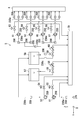
- FIG. 9 is a diagram showing the piping of the processing liquid cabinet 5.
- the substrate processing apparatus 100 includes a supply pipe 13, a branch pipe 19, a supply control unit 2, and a valve 23 for each processing unit 1 in each tower TW.
- the supply adjusting section 2 is accommodated in a fluid box 4 corresponding to the tower TW.
- a part of each supply pipe 13 is housed in the chamber 10, and another part of each supply pipe 13 is housed in the fluid box 4.
- the branch pipe 19 indicates a pipe branched from the supply pipe 13.
- the branch pipe 19 is connected to a drain tank 70 (FIG. 9) of the processing liquid cabinet 5 via the valve 23. By opening and closing the valve 23, it is controlled whether or not the processing liquid in the branch pipe 19 is discharged.
- the processing liquid in the branch pipe 19 is discharged to the drain tank 70 by opening the valve 23.
- the processing liquid cabinet 5 includes a plurality of primary filters, a plurality of secondary filters, a plurality of valves, a plurality of flow control valves, a plurality of processing liquid tanks, a plurality of pipes, And a drain tank 70.
- the plurality of primary filters include a primary filter 51 and a primary filter 52.
- the plurality of secondary filters include a secondary filter 61, a secondary filter 63, a secondary filter 65, and a secondary filter 67.
- the plurality of valves include a valve 53, a valve 54, a valve 55, a valve 59, a valve 62, a valve 64, a valve 66, and a valve 68.
- the plurality of flow control valves include a flow control valve 56 and a flow control valve 60.
- the plurality of processing liquid tanks include a processing liquid tank 57 and a processing liquid tank 58.
- the plurality of pipes include a pipe 230a, a pipe 230b, a pipe 230c, a pipe 230d, and a pipe 230e.
- the pipe 230a is a pipe connected to the upstream side of the primary filter 51.
- the pipe 230b is a pipe connected to the downstream side of the primary filter 52 and connected to the processing liquid tank 57 and the upstream side of the processing liquid tank 58.
- the pipe 230c is a pipe connected to the processing liquid tank 57 and the downstream side of the processing liquid tank 58.
- the pipe 230d is a branched pipe connected to the upstream of the secondary filter 61, the secondary filter 63, the secondary filter 65, and the secondary filter 67.
- the pipe 230e is a branched pipe connected to the upstream side of the fluid box 4.
- the treatment liquid (IPA) is supplied to the primary filter 51 through the pipe 230a.
- the primary filter 51 and the primary filter 52 remove foreign matter from the processing liquid flowing through the pipe.
- the primary filter 51 is connected to the primary filter 52.
- the primary filter 51 is connected to a drain tank 70 via a valve 53.
- the primary filter 52 is connected to a drain tank 70 via a valve 54.
- the metal removing device 200 is disposed, for example, at any location in the pipe 230a. Therefore, the processing liquid from which the metal has been removed by the metal removing device 200 is supplied to the primary filter 51.
- the primary filter 52 is connected to the processing liquid tank 57 and the processing liquid tank 58 via a pipe 230b.
- the processing liquid tank 57 and the processing liquid tank 58 store the processing liquid.
- the processing liquid tank 57 is connected to a drain tank 70 via a valve 55 and a flow control valve 56.
- the processing liquid tank 58 is connected to a drain tank 70 via a valve 59 and a flow control valve 60.
- the metal removing device 200 is disposed, for example, at any location in the pipe 230b. Therefore, the processing liquid from which the metal has been removed by the metal removing device 200 is supplied to the processing liquid tank 57 and the processing liquid tank 58.
- the treatment liquid tank 57 is connected to the secondary filters 65 and 67 via the pipes 230c and 230d.
- the processing liquid tank 58 is connected to the secondary filters 61 and 63 via the pipes 230c and 230d.
- the pipe 230d is a pipe from which the pipe 230c branches.
- the secondary filter 65 and the secondary filter 67 remove foreign matter from the processing liquid flowing through the pipe.
- the metal removing device 200 is disposed, for example, at any location in the pipe 230c. Further, the metal removing device 200 is disposed, for example, at any location in the pipe 230d. Therefore, the processing liquid from which the metal has been removed by the metal removing device 200 is supplied to the secondary filter 61, the secondary filter 63, the secondary filter 65, and the secondary filter 67.
- Each of the secondary filter 61, the secondary filter 63, the secondary filter 65, and the secondary filter 67 is connected to the fluid box 4 via a pipe 230e.
- the pipe 230e is a branched pipe.
- the metal removing device 200 is disposed, for example, at any location in the branched pipe 230e. Therefore, the processing liquid from which the metal has been removed by the metal removing device 200 is supplied to the fluid box 4.
- the metal removing device 200 is disposed in each of the primary filter 51, the primary filter 52, the secondary filter 61, the secondary filter 63, the secondary filter 65, and the secondary filter 67, for example.
- the magnetic field generating unit 220 is attached to each of the housings of the primary filter 51, the primary filter 52, the secondary filter 61, the secondary filter 63, the secondary filter 65, and the secondary filter 67. Therefore, metal that cannot be removed by the filter can be removed by the metal removing device 200.
- the metal removing device 200 is arranged at any point in a pipe connected to the upstream side of the supply adjusting unit 2 in the fluid box 4. Further, the metal removing device 200 is disposed at any position in the supply pipe 13 up to the nozzle 12 disposed downstream of the flow control valve 22. Therefore, the processing liquid from which the metal has been removed by the metal removing device 200 is discharged from the nozzle 12 toward the substrate W.
- the trap section 210 be removable from the pipe 230.
- the trap unit 210 is connected to the pipe 230 via a joint, and may be removable. In this case, it is preferable that the trap unit 210 can be removed without stopping the flow of the processing liquid by providing a bypass route by using a three-way valve.
- the magnetic field generator 220 disposed on the outer peripheral surface 232 of the pipe 230 be removable. Removing the magnetic field generator 220 eliminates the magnetic field. As a result, the metal trapped by the trap unit 210 is released from the trap unit 210. In this case, it is preferable that the metal released from the trap section 210 be discharged to the drain tank 70.
- the magnetic field generator 220 When the magnetic field generator 220 is an electromagnet, the magnetic field H can be prevented from acting on the processing liquid by stopping the current supplied to the electromagnet. Therefore, the metal trapped by the trap unit 210 is released from the trap unit 210. It is preferable that the metal released from the trap unit 210 be discharged to the drain tank 70.
- FIG. 1 to 9 The embodiments of the present invention have been described with reference to the drawings (FIGS. 1 to 9).
- the present invention is not limited to the above embodiment, and can be implemented in various modes without departing from the gist thereof.
- each component is schematically shown mainly for easy understanding, and the thickness, length, number, etc. of each component shown are different from the actual ones for the convenience of drawing. .
- the materials, shapes, dimensions, and the like of the respective constituent elements shown in the above-described embodiments are merely examples, and are not particularly limited, and various changes can be made without substantially departing from the effects of the present invention. is there.
- Metal removing device 210 Trap unit 220, 220a, 220b Magnetic field generation unit 230, 230a, 230b, 230c, 230d, 230e Pipe 232 Outer surface 233 Inner surface 234 Flow unit 235 Bent unit 240 Processing liquid supply source 250 Processing liquid storage unit M metal W substrate
Landscapes
- Cleaning Or Drying Semiconductors (AREA)
Abstract
金属除去装置(200)は、基板(W)を処理する処理液中に含まれる金属(M)を除去する。金属除去装置(200)は、磁界発生部(220)と、トラップ部(210)とを備える。磁界発生部(220)は、処理液供給源から供給される処理液に磁界を作用させる。トラップ部(210)は、磁界の作用を受けて処理液中を移動する金属(M)を捕捉する。
Description
本発明は、金属除去装置、基板処理装置および基板処理方法に関する。
基板処理装置において、基板に処理液を供給して処理が行われる。処理液に異物が含まれていると歩留まりが悪化するため、フィルターを用いて処理液中の異物を除去することが行われる(例えば、特許文献1)。特許文献1の半導体基板洗浄装置では、フィルターでメタル不純物を吸着している。
しかしながら、フィルターでは、処理液中に含まれる金属が除去できない可能性があった。
本発明は上記課題に鑑みてなされたものであり、その目的は処理液中の金属を除去することができる金属除去装置、基板処理装置および基板処理方法を提供することにある。
本発明に係る金属除去装置は、基板を処理する処理液中に含まれる金属を除去する。金属除去装置は、磁界発生部と、トラップ部とを備える。前記磁界発生部は、処理液供給源から供給される処理液に磁界を作用させる。前記トラップ部は、前記磁界の作用を受けて処理液中を移動する前記金属を捕捉する。
ある実施形態において、金属除去装置は、配管をさらに備える。前記配管は、前記処理液供給源に接続される。前記トラップ部は、前記配管に配置される。
ある実施形態において、前記配管は、流通部を有する。前記流通部は、前記処理液が流通し前記トラップ部に隣接する。前記トラップ部における前記処理液の流速は、前記流通部における前記処理液の流速よりも遅い。
ある実施形態において、前記配管は、非磁性体材料から形成される。
ある実施形態において、前記配管は、パーフルオロアルコキシエチレンから形成される。
ある実施形態において、前記トラップ部は、前記配管の径が変化する箇所に配置される。
ある実施形態において、前記配管は、曲がっている曲がり部をさらに有する。前記トラップ部は、前記曲がり部に配置される。
ある実施形態において、前記トラップ部において、前記配管の内周面は凸凹形状を有する。
ある実施形態において、前記トラップ部は前記配管から取り外し可能である。または、前記配管の外周面に配置された前記磁界発生部は取り外し可能である。
ある実施形態において、前記磁界発生部は電磁石を含む。前記磁界発生部は、前記処理液に磁界を作用させるか否かを切り換え可能である。
ある実施形態において、前記金属除去装置は、配管と、処理液収容部とをさらに備える。前記配管は、前記処理液供給源に接続される。前記処理液収容部は、前記配管に接続される。前記処理液収容部は、前記処理液を収容する。前記トラップ部は、前記処理液収容部に配置される。
ある実施形態において、前記処理液は無極性または低極性である。
ある実施形態において、前記処理液はイソプロピルアルコールを含む。
本発明に係る基板処理装置は、上記に記載の金属除去装置を備える。前記基板処理装置は、前記金属除去装置を通過した前記処理液によって前記基板を処理する。
本発明に係る基板処理方法は、処理液供給源から配管に処理液を供給する工程と、磁界発生部によって発生する磁界によって、前記処理液中を移動した金属を捕捉して前記処理液中に含まれる前記金属を除去する工程と、前記金属を除去された前記処理液によって基板を処理する工程とを包含する。
ある実施形態において、前記基板処理方法は、捕捉した金属を解放することによって排出する排出工程をさらに包含する。
本発明の金属除去装置によれば、処理液中の金属を除去することができる。
以下、本発明の実施形態について、図面を参照しながら説明する。なお、図中、同一または相当部分については同一の参照符号を付して説明を繰り返さない。また、本発明の実施形態において、X軸、Y軸、およびZ軸は互いに直交し、X軸およびY軸は水平方向に平行であり、Z軸は鉛直方向に平行である。
[実施形態1]
図1を参照して、本発明の実施形態に係る基板処理装置100について説明する。まず、図1を参照して基板処理装置100を説明する。図1は、基板処理装置100を示す図である。図1に示すように、基板処理装置100は、基板Wを処理液によって処理する。具体的には、基板処理装置100は、基板Wを1枚ずつ処理する枚葉型である。基板Wは略円板状である。
図1を参照して、本発明の実施形態に係る基板処理装置100について説明する。まず、図1を参照して基板処理装置100を説明する。図1は、基板処理装置100を示す図である。図1に示すように、基板処理装置100は、基板Wを処理液によって処理する。具体的には、基板処理装置100は、基板Wを1枚ずつ処理する枚葉型である。基板Wは略円板状である。
基板処理装置100は、処理ユニット1と、供給調節部2と、金属除去装置200とを備える。
処理ユニット1は、基板Wに処理液を吐出して、基板Wを処理する。具体的には、処理ユニット1は、チャンバー10と、スピンチャック11と、ノズル12と、供給配管13と、ノズル移動ユニット14と、カップ16とを含む。
チャンバー10は略箱形状を有する。チャンバー10は、基板W、スピンチャック11、ノズル12、供給配管13の一部、ノズル移動ユニット14、およびカップ16を収容する。スピンチャック11は、基板Wを保持して回転する。具体的には、スピンチャック11は、チャンバー10内で基板Wを水平に保持しながら、回転軸線A1の回りに基板Wを回転させる。
スピンチャック11は、複数のチャック部材110と、スピンベース111と、スピンモーター112とを含む。複数のチャック部材110は基板Wを水平な姿勢で保持する。スピンベース111は、略円板状であり、水平な姿勢で複数のチャック部材110を支持する。スピンモーター112は、スピンベース111を回転させることによって、複数のチャック部材110に保持された基板Wを回転軸線A1の回りに回転させる。
ノズル12は、基板Wに向けて処理液を吐出する。処理液は、例えば、無極性または低極性である。処理液は、例えば、イソプロピルアルコール(isopropyl alcohol:IPA)を含む。
供給配管13はノズル12に接続される。供給配管13はノズル12に処理液を供給する。
供給調節部2は、ノズル12への処理液の供給量を調節する。供給調節部2は、チャンバー10の外部において供給配管13に配置される。なお、供給調節部2は、チャンバー10の内部において供給配管13に配置されてもよい。
具体的には、供給調節部2は、ノズル12への処理液の供給量をゼロにして、ノズル12への処理液の供給を停止する。供給調節部2は、ノズル12への処理液の供給量をゼロより多くして、ノズル12へ処理液を供給する。供給調節部2は、ノズル12へ供給する処理液の流量を調節する。
さらに具体的には、供給調節部2は、バルブ20と、流量計21と、流量調整バルブ22とを含む。ノズル12に対する処理液の供給開始および供給停止は、バルブ20によって切り替えられる。具体的には、バルブ20は、開閉バルブであり、開状態と閉状態とに切り替え可能である。開状態とは、ノズル12に向かって供給配管13内を流れる処理液を通過させる状態のことである。閉状態とは、供給配管13からノズル12への処理液の供給を停止する状態のことである。
流量計21は、ノズル12に供給される処理液の流量を検出する。流量調整バルブ22は、ノズル12に供給される処理液の流量を調整する。バルブ20が開状態になると、処理液が、流量調整バルブ22の開度に対応する流量で供給配管13からノズル12に供給される。その結果、ノズル12から処理液が吐出される。開度は、流量調整バルブ22が開いている程度を示す。
カップ16は略筒形状を有する。カップ16は、基板Wから排出された処理液を受け止める。
ノズル移動ユニット14は、回動軸線A2の回りに回動して、ノズル12を水平に移動させる。具体的には、ノズル移動ユニット14は、ノズル12の処理位置と待機位置との間で、ノズル12を水平に移動させる。処理位置は、基板Wの上方の位置を示す。待機位置は、スピンチャック11およびカップ16よりも外側の位置を示す。また、ノズル移動ユニット14は、ノズル12を鉛直に移動させることもできる。
金属除去装置200は、基板Wを処理する処理液中に含まれる金属を除去する。基板処理装置100は、金属除去装置200を通過した処理液によって基板Wを処理する。
図2(a)および図2(b)を参照して、本発明の実施形態に係る金属除去装置200について説明する。図2(a)および図2(b)は、金属除去装置200を示す模式的な断面図である。
図2(a)および図2(b)に示すように、金属除去装置200は、トラップ部210と、磁界発生部220と、配管230とを備える。
配管230は、基板Wを処理する処理液が流通する。ここでは、処理液は、配管230内を図の左方から右方に流れる。すなわち、図の左側が上流側であり、図の右側が下流側である。処理液の流速は、例えば、0.64m/秒である。処理液には、不純物として金属Mが含まれる。金属は、例えば、アルミニウム、クロム、鉄および亜鉛である。金属除去装置200は、処理液中に含まれる金属を除去する。配管230は、処理液供給源に接続される。配管230は、処理液が流通する流通部234を有する。流通部234は、トラップ部210に隣接する。配管230は、例えば、非磁性体材料から形成される。詳しくは、配管230は、例えば、パーフルオロアルコキシエチレンから形成される。
磁界発生部220は、例えば、ネオジウム磁石である。磁界発生部220aは、N極の磁石である。磁界発生部220bは、S極の磁石である。磁界発生部220は、例えば、配管230の外周面232に取り付けられる。詳しくは、磁界発生部220aと磁界発生部220bとで配管230を挟み込むように、磁界発生部220aと磁界発生部220bとは、配管230の外周面232に取り付けられる。したがって、磁界発生部220は、トラップ部210内の処理液に磁界Hを作用させる。磁束密度は、例えば、200mTである。なお、磁界発生部220は、電磁石でもよい。磁界発生部220が電磁石である場合、処理液に磁界Hを作用させるか否かを容易に切り換えることができる。
トラップ部210は、配管230に配置される。具体的には、トラップ部210は、配管230の一部を構成する。詳しくは、トラップ部210は、配管230のうち、磁界発生部220が配置されている部分を示す。トラップ部210には、処理液供給源から供給された処理液が流通する。図2(a)に示すように、磁界Hによって、処理液に含まれる金属Mがトラップ部210に向けて移動する。したがって、図2(b)に示すように、トラップ部210は、磁界Hの作用を受けて処理液中を移動する金属Mを捕捉する。
続いて、本発明の実施形態における基板処理方法について説明する。基板処理方法は、供給工程と、除去工程と、処理工程とを含む。供給工程において、図2(a)に示すように、処理液供給源から配管230に処理液を供給する。除去工程において、図2(b)に示すように、磁界発生部220によって発生する磁界によって、処理液中を移動した金属を捕捉して処理液中に含まれる金属を除去する。処理工程において、金属を除去された処理液によって基板Wを処理する。本発明の実施形態における基板処理方法によれば、金属を除去された処理液によって基板Wを処理することができる。したがって、歩留まりを向上させることができる。また、基板処理方法は、排出工程をさらに含むことが好ましい。排出工程において、捕捉した金属を解放することによって排出する。金属の排出については図8および図9を参照して後述する。
図3を参照して、本発明の実施形態における金属除去装置の金属の捕捉結果について説明する。図3は、本発明の実施形態における金属除去装置の金属の捕捉結果を示す図である。図3において、横軸は、処理液中に含まれる金属を示す。図3において、縦軸は、処理液中に含まれる金属の量を示す。縦軸の単位は、E10 atomos/cm2である。図3において、データL1は、配管に磁界発生部を設けなかった場合のデータを示す。図3において、データL2は、配管230に磁界発生部220を設けた場合のデータを示す。測定条件として、処理液は、IPAであり、磁束密度は、200mTであり、処理液の流速は、0.64m/秒であり、配管230の直径は10mmである。
図3に示すように、データL1に比べて、データL2では、処理液に含まれる金属の量が減っていることが確認できた。特に、アルミニウム(Al)、クロム(Cr)、鉄(Fe)および亜鉛(Zn)が減っていることが確認できた。アルミニウムは、磁性体としては磁性が弱いが、アルミニウムが処理液中から除去されていることが確認できた。磁性が強い鉄と一緒に塊となって、鉄と一緒にアルミニウムがトラップ部210によって捕捉されるためである。
以上、図1~図3を参照して説明したように、トラップ部210は、磁界Hの作用を受けて処理液中を移動する金属を捕捉する。したがって、処理液中の金属を除去することができる。その結果、処理液の純度が向上し、歩留まりを向上させることができる。
また、トラップ部210は、配管230に配置される。したがって、配管230内に流れる処理液中の金属を除去することができる。その結果、処理液の純度が向上し、歩留まりを向上させることができる。
また、配管230は、非磁性体材料から形成される。したがって、磁界発生部220がトラップ部210内の処理液に磁界を作用させる妨げにならない。このため、磁界発生部220がトラップ部210内の処理液に磁界を作用させることができる。その結果、トラップ部210は、磁界Hによって処理液中を移動した金属を捕捉することができる。
また、処理液は、無極性または低極性である。したがって、磁界発生部220がトラップ部210内の処理液に磁界を作用させることができる。その結果、イオン交換方式のフィルターでは除去できない処理液中の金属を捕捉することができる。
[実施形態2]
図1~図3を参照して説明した金属除去装置200では、トラップ部210は配管230に配置されていたが、トラップ部210は処理液収容部250に配置されてもよい。
図1~図3を参照して説明した金属除去装置200では、トラップ部210は配管230に配置されていたが、トラップ部210は処理液収容部250に配置されてもよい。
図4を参照して、本発明の実施形態2に係る金属除去装置200について説明する。図4は、金属除去装置200を示す模式的な断面図である。トラップ部210が処理液収容部250に配置される点で、実施形態2に係る金属除去装置200は、実施形態1に係る金属除去装置200と主に異なる。以下、実施形態2が実施形態1と異なる点を主に説明する。
図4に示すように、金属除去装置200は、トラップ部210と、磁界発生部220と、配管230とに加えて、処理液供給源240と、処理液収容部250とを備える。
磁界発生部220は、処理液収容部250の外周面に取り付けられる。
配管230は、処理液供給源240に接続されている。
処理液供給源240は、配管230を介して処理液収容部250に処理液を供給する。処理液供給源240は、例えば、タンクである。
処理液収容部250は、配管230に接続されている。処理液収容部250は、処理液を収容する。処理液収容部250は、例えば、処理液供給源240よりも小さいタンクである。処理液収容部250における処理液の流速は0に近い。
トラップ部210は、処理液収容部250に配置される。処理液収容部250における処理液の流速は0に近い。したがって、トラップ部210は、磁界Hによって処理液中を移動した金属を捕捉し易くなる。その結果、処理液中の金属を除去することができる。
[実施形態3]
図1~図3を参照して説明した金属除去装置200では、トラップ部210は配管230の直線状の部分に配置されていたが、トラップ部210は配管230の直線状の部分以外に配置されてもよい。
図1~図3を参照して説明した金属除去装置200では、トラップ部210は配管230の直線状の部分に配置されていたが、トラップ部210は配管230の直線状の部分以外に配置されてもよい。
図5(a)~(d)を参照して、本発明の実施形態3に係る金属除去装置200について説明する。図5(a)~(d)は、金属除去装置200を示す模式的な断面図である。トラップ部210が配管230の直線状の部分以外に配置されている点で、実施形態3に係る金属除去装置200は、実施形態1に係る金属除去装置200と主に異なる。以下、実施形態3が実施形態1と異なる点を主に説明する。なお、図5(a)~図5(d)では、図面の簡略化のため、磁界発生部220は省略している。
図5(a)に示すように、配管230の径は、d1からd2に大きくなっている。トラップ部210は、配管230の径が変化する箇所に配置される。配管230の径が変化する箇所では、処理液の流速は低下する。すなわち、トラップ部210における処理液の流速は、流通部234における処理液の流速よりも遅い。したがって、トラップ部210は、磁界Hによって処理液中を移動した金属を捕捉し易くなる。
図5(b)に示すように、配管230は、曲がり部235を有する。曲がり部235は、配管230が曲がっている箇所である。トラップ部210は、曲がり部235に配置される。曲がり部235では、圧力損失によって、処理液の流速は低下する。すなわち、トラップ部210における処理液の流速は、流通部234における処理液の流速よりも遅い。したがって、トラップ部210は、磁界Hによって処理液中を移動した金属を捕捉し易くなる。その結果、処理液中の金属を除去することができる。
図5(c)に示すように、配管230は、曲がり部235を有する。曲がり部235は、配管230が曲がっている箇所である。曲がり部235において、配管230が凹んでいる。トラップ部210は、曲がり部235に配置される。曲がり部235では、圧力損失によって、処理液の流速は低下する。すなわち、トラップ部210における処理液の流速は、流通部234における処理液の流速よりも遅い。したがって、トラップ部210は、磁界Hによって処理液中を移動した金属を捕捉し易くなる。その結果、処理液中の金属を除去することができる。
図5(d)に示すように、配管230は、複数の曲がり部235を有する。曲がり部235は、配管230が曲がっている箇所である。トラップ部210は、複数の曲がり部235のそれぞれに配置される。曲がり部235では、圧力損失によって、処理液の流速は低下する。すなわち、トラップ部210における処理液の流速は、流通部234における処理液の流速よりも遅い。したがって、トラップ部210は、磁界Hによって処理液中を移動した金属を捕捉し易くなる。その結果、処理液中の金属を除去することができる。
[実施形態4]
なお、配管230の内周面233は、凸凹形状を有していてもよい。
なお、配管230の内周面233は、凸凹形状を有していてもよい。
図6を参照して、本発明の実施形態4に係る金属除去装置200について説明する。図6は、金属除去装置200を示す模式的な断面図である。配管230の内周面233が凸凹形状を有する点で、実施形態4に係る金属除去装置200は、実施形態1に係る金属除去装置200と主に異なる。以下、実施形態4が実施形態1と異なる点を主に説明する。
図6に示すように、トラップ部210において、配管230の内周面233は、凹凸形状を有する。したがって、トラップ部210は、磁界Hによって処理液中を移動した金属を捕捉し易くなる。その結果、処理液中の金属を除去することができる。
[実施形態5]
図7~図9を参照して、本発明の実施形態5に係る基板処理装置100について説明する。実施形態5が複数の処理ユニット1を備えている点で、実施形態5は実施形態1と異なる。以下、実施形態5が実施形態1と異なる点を主に説明する。
図7~図9を参照して、本発明の実施形態5に係る基板処理装置100について説明する。実施形態5が複数の処理ユニット1を備えている点で、実施形態5は実施形態1と異なる。以下、実施形態5が実施形態1と異なる点を主に説明する。
まず、図7を参照して、基板処理装置100について説明する。図7は、基板処理装置100を示す平面図である。図7に示すように、基板処理装置100は、複数のロードポートLPと、インデクサーロボットIRと、センターロボットCRと、複数の処理ユニット1と、複数の流体ボックス4と、処理液キャビネット5とを備える。
ロードポートLPの各々は、複数枚の基板Wを積層して収容する。インデクサーロボットIRは、ロードポートLPとセンターロボットCRとの間で基板Wを搬送する。センターロボットCRは、インデクサーロボットIRと処理ユニット1との間で基板Wを搬送する。処理ユニット1の各々は、基板Wに処理液を吐出して、基板Wを処理する。流体ボックス4の各々は流体機器を収容する。処理液キャビネット5は処理液を収容する。
具体的には、複数の処理ユニット1は、平面視においてセンターロボットCRを取り囲むように配置された複数のタワーTW(実施形態5では4つのタワーTW)を形成している。各タワーTWは、上下に積層された複数の処理ユニット1(実施形態5では3つの処理ユニット1)を含む。複数の流体ボックス4は、それぞれ、複数のタワーTWに対応している。処理液キャビネット5内の処理液は、いずれかの流体ボックス4を介して、流体ボックス4に対応するタワーTWに含まれる全ての処理ユニット1に供給される。
また、実施形態5では、基板処理装置100は、チャンバー10ごとに、スピンチャック11とノズル12と供給調節部2とを備える。チャンバー10の各々は、スピンチャック11とノズル12と供給調節部2とを収容する。
次に、図8および図9を参照して、ノズル12への処理液の供給について説明する。図8は、基板処理装置100の配管を示す図である。図9は、処理液キャビネット5の配管を示す図である。図8に示すように、基板処理装置100は、各タワーTWにおいて、処理ユニット1ごとに、供給配管13と分岐配管19と供給調節部2とバルブ23とを備えている。供給調節部2は、タワーTWに対応する流体ボックス4に収容される。各供給配管13の一部はチャンバー10に収容され、各供給配管13の他の一部は流体ボックス4に収容される。分岐配管19は、供給配管13から分岐した配管を示す。分岐配管19は、バルブ23を介して処理液キャビネット5のドレンタンク70(図9)に接続される。バルブ23を開閉することによって、分岐配管19内の処理液を排出するか否かを制御している。例えば、バルブ23を開状態することによって、分岐配管19内の処理液をドレンタンク70に排出する。
図9に示すように、処理液キャビネット5は、複数の一次フィルターと、複数の二次フィルターと、複数のバルブと、複数の流量調整バルブと、複数の処理液タンクと、複数の配管と、ドレンタンク70とを有する。複数の一次フィルターは、一次フィルター51と、一次フィルター52とを含む。複数の二次フィルターは、二次フィルター61と、二次フィルター63と、二次フィルター65と、二次フィルター67とを含む。複数のバルブは、バルブ53と、バルブ54と、バルブ55と、バルブ59と、バルブ62、バルブ64と、バルブ66と、バルブ68とを含む。複数の流量調整バルブは、流量調整バルブ56と、流量調整バルブ60とを含む。複数の処理液タンクは、処理液タンク57と、処理液タンク58とを含む。複数の配管は、配管230aと、配管230bと、配管230cと、配管230dと、配管230eとを含む。
配管230aは、一次フィルター51の上流側に接続される配管を示す。配管230bは、一次フィルター52の下流側に接続され、処理液タンク57および処理液タンク58の上流側に接続される配管を示す。配管230cは、処理液タンク57および処理液タンク58の下流側に接続される配管を示す。配管230dは、二次フィルター61、二次フィルター63、二次フィルター65および二次フィルター67の上流側に接続される分岐した配管を示す。配管230eは、流体ボックス4の上流側に接続される分岐した配管を示す。
処理液(IPA)は、配管230aを流通して一次フィルター51に供給される。一次フィルター51と、一次フィルター52とは、配管を流れる処理液から異物を除去する。一次フィルター51は、一次フィルター52と接続している。一次フィルター51は、バルブ53を介してドレンタンク70と接続している。一次フィルター52は、バルブ54を介してドレンタンク70と接続している。金属除去装置200は、例えば、配管230a中のいずれかの箇所に配置される。したがって、一次フィルター51には、金属除去装置200によって金属を除去された処理液が供給される。
一次フィルター52は、配管230bを介して、処理液タンク57と処理液タンク58とに接続している。処理液タンク57と処理液タンク58とには処理液が収容されている。処理液タンク57は、バルブ55および流量調整バルブ56を介してドレンタンク70と接続している。処理液タンク58は、バルブ59および流量調整バルブ60を介してドレンタンク70と接続している。金属除去装置200は、例えば、配管230b中のいずれかの箇所に配置される。したがって、処理液タンク57および処理液タンク58には、金属除去装置200によって金属を除去された処理液が供給される。
処理液タンク57は、配管230cおよび配管230dを介して、二次フィルター65および二次フィルター67と接続している。処理液タンク58は、配管230cおよび配管230dを介して、二次フィルター61および二次フィルター63と接続している。配管230dは、配管230cが分岐した配管である。二次フィルター65と、二次フィルター67とは、配管を流れる処理液から異物を除去する。金属除去装置200は、例えば、配管230c中のいずれかの箇所に配置される。また、金属除去装置200は、例えば、配管230d中のいずれかの箇所に配置される。したがって、二次フィルター61、二次フィルター63、二次フィルター65および二次フィルター67には、金属除去装置200によって金属を除去された処理液が供給される。
二次フィルター61、二次フィルター63、二次フィルター65および二次フィルター67の各々は、配管230eを介して流体ボックス4と接続している。配管230eは、分岐した配管である。金属除去装置200は、例えば、分岐した配管230e中のいずれかの箇所に配置される。したがって、流体ボックス4には、金属除去装置200によって金属を除去された処理液が供給される。
また、金属除去装置200は、例えば、一次フィルター51、一次フィルター52、二次フィルター61、二次フィルター63、二次フィルター65および二次フィルター67の各々に配置される。詳しくは、一次フィルター51、一次フィルター52、二次フィルター61、二次フィルター63、二次フィルター65および二次フィルター67の各々のハウジングに、磁界発生部220が取り付けられる。したがって、フィルターでは除去できない金属を、金属除去装置200によって除去することができる。
再び、図8を参照する。図8に示すように、金属除去装置200は、流体ボックス4内の供給調節部2の上流側に接続される配管中のいずれかの箇所に配置される。また、金属除去装置200は、流量調整バルブ22の下流側に配置されるノズル12までの供給配管13中のいずれかの箇所に配置される。したがって、金属除去装置200によって金属を除去された処理液を、基板Wに向けてノズル12は吐出する。
なお、トラップ部210は配管230から取り外し可能であることが好ましい。例えば、トラップ部210は、継ぎ手を介して配管230を接続されており、取り外し可能にしてよい。この場合、三方弁を用いることによってバイパスルートを設けることによって処理液の流れを止めることなくトラップ部210を取り外せることが好ましい。また、配管230の外周面232に配置された磁界発生部220は、取り外し可能であることが好ましい。磁界発生部220を取り外すことによって、磁界が無くなる。その結果、トラップ部210によって捕捉されていた金属がトラップ部210から解放される。この場合、トラップ部210から解放された金属は、ドレンタンク70に排出されることが好ましい。
また、磁界発生部220が電磁石である場合、電磁石に与える電流を停止することによって、処理液に磁界Hを作用させなくすることができる。したがって、トラップ部210によって捕捉されていた金属がトラップ部210から解放される。トラップ部210から解放された金属は、ドレンタンク70に排出されることが好ましい。
図8に示す供給配管13中に配置される金属除去装置200を例にして、捕捉した金属の排出を説明する。まず、電磁石に与える電流を停止することによって、処理液に磁界Hを作用させなくする。その結果、トラップ部210によって捕捉されていた金属がトラップ部210から解放される。この際、バルブ23を開状態することによって、分岐配管19内の処理液がドレンタンク70に排出される。すなわち、トラップ部210から解放された金属は、ドレンタンク70に排出される。
以上、図面(図1~図9)を参照しながら本発明の実施形態を説明した。但し、本発明は、上記の実施形態に限られるものではなく、その要旨を逸脱しない範囲で種々の態様において実施することが可能である。図面は、理解しやすくするために、それぞれの構成要素を主体に模式的に示しており、図示された各構成要素の厚み、長さ、個数等は、図面作成の都合上から実際とは異なる。また、上記の実施形態で示す各構成要素の材質や形状、寸法等は一例であって、特に限定されるものではなく、本発明の効果から実質的に逸脱しない範囲で種々の変更が可能である。
200 金属除去装置
210 トラップ部
220、220a、220b 磁界発生部
230、230a、230b、230c、230d、230e 配管
232 外周面
233 内周面
234 流通部
235 曲がり部
240 処理液供給源
250 処理液収容部
M 金属
W 基板
210 トラップ部
220、220a、220b 磁界発生部
230、230a、230b、230c、230d、230e 配管
232 外周面
233 内周面
234 流通部
235 曲がり部
240 処理液供給源
250 処理液収容部
M 金属
W 基板
Claims (16)
- 基板を処理する処理液中に含まれる金属を除去する金属除去装置であって、
処理液供給源から供給される処理液に磁界を作用させる磁界発生部と、
前記磁界の作用を受けて処理液中を移動する前記金属を捕捉するトラップ部とを備える、金属除去装置。 - 前記処理液供給源に接続された配管をさらに備え、
前記トラップ部は、前記配管に配置される、請求項1に記載の金属除去装置。 - 前記配管は、流通部を有し、
前記流通部は、前記処理液が流通し前記トラップ部に隣接し、
前記トラップ部における前記処理液の流速は、前記流通部における前記処理液の流速よりも遅い、請求項2に記載の金属除去装置。 - 前記配管は、非磁性体材料から形成される、請求項2または請求項3に記載の金属除去装置。
- 前記配管は、パーフルオロアルコキシエチレンから形成される、請求項2から請求項4のいずれか1項に記載の金属除去装置。
- 前記トラップ部は、前記配管の径が変化する箇所に配置される、請求項2から請求項5のいずれか1項に記載の金属除去装置。
- 前記配管は、曲がっている曲がり部をさらに有し、
前記トラップ部は、前記曲がり部に配置される、請求項2から請求項6のいずれか1項に記載の金属除去装置。 - 前記トラップ部において、前記配管の内周面は凸凹形状を有する、請求項2から請求項7のいずれか1項に記載の金属除去装置。
- 前記トラップ部は前記配管から取り外し可能である、または、前記配管の外周面に配置された前記磁界発生部は取り外し可能である、請求項2から請求項8のいずれか1項に記載の金属除去装置。
- 前記磁界発生部は電磁石を含み、前記処理液に磁界を作用させるか否かを切り換え可能である、請求項1から請求項8のいずれか1項に記載の金属除去装置。
- 前記処理液供給源に接続された配管と、
前記配管に接続され、前記処理液を収容する処理液収容部と
をさらに備え、
前記トラップ部は、前記処理液収容部に配置される、請求項1に記載の金属除去装置。 - 前記処理液は無極性または低極性である、請求項1から請求項11のいずれか1項に記載の金属除去装置。
- 前記処理液はイソプロピルアルコールを含む、請求項1から請求項12のいずれか1項に記載の金属除去装置。
- 請求項1から請求項13のいずれか1項に記載の金属除去装置を備え、
前記金属除去装置を通過した前記処理液によって前記基板を処理する、基板処理装置。 - 処理液供給源から配管に処理液を供給する工程と、
磁界発生部によって発生する磁界によって、前記処理液中を移動した金属を捕捉して前記処理液中に含まれる前記金属を除去する工程と、
前記金属を除去された前記処理液によって基板を処理する工程と
を包含する、基板処理方法。 - 捕捉した金属を解放することによって排出する排出工程をさらに包含する、請求項15に記載の基板処理方法。
Applications Claiming Priority (2)
| Application Number | Priority Date | Filing Date | Title |
|---|---|---|---|
| JP2018-159180 | 2018-08-28 | ||
| JP2018159180A JP7215853B2 (ja) | 2018-08-28 | 2018-08-28 | 金属除去装置、基板処理装置および基板処理方法 |
Publications (1)
| Publication Number | Publication Date |
|---|---|
| WO2020044879A1 true WO2020044879A1 (ja) | 2020-03-05 |
Family
ID=69644184
Family Applications (1)
| Application Number | Title | Priority Date | Filing Date |
|---|---|---|---|
| PCT/JP2019/028845 Ceased WO2020044879A1 (ja) | 2018-08-28 | 2019-07-23 | 金属除去装置、基板処理装置および基板処理方法 |
Country Status (3)
| Country | Link |
|---|---|
| JP (1) | JP7215853B2 (ja) |
| TW (1) | TWI717791B (ja) |
| WO (1) | WO2020044879A1 (ja) |
Cited By (1)
| Publication number | Priority date | Publication date | Assignee | Title |
|---|---|---|---|---|
| WO2025062957A1 (ja) * | 2023-09-22 | 2025-03-27 | 株式会社Screenホールディングス | 基板処理装置および基板処理方法 |
Citations (4)
| Publication number | Priority date | Publication date | Assignee | Title |
|---|---|---|---|---|
| JPH0760292A (ja) * | 1993-08-31 | 1995-03-07 | Toshiba Corp | 高純度酸、高純度水の製造方法 |
| JPH09164388A (ja) * | 1995-12-15 | 1997-06-24 | Toshiba Corp | イオン水生成装置、イオン水生成方法及び半導体装置の製造方法 |
| JP2006239563A (ja) * | 2005-03-03 | 2006-09-14 | Kansai Electric Power Co Inc:The | 異物連続除去装置 |
| JP2017170288A (ja) * | 2016-03-22 | 2017-09-28 | トリニティ工業株式会社 | 金属除去装置 |
-
2018
- 2018-08-28 JP JP2018159180A patent/JP7215853B2/ja active Active
-
2019
- 2019-07-23 WO PCT/JP2019/028845 patent/WO2020044879A1/ja not_active Ceased
- 2019-07-29 TW TW108126813A patent/TWI717791B/zh active
Patent Citations (4)
| Publication number | Priority date | Publication date | Assignee | Title |
|---|---|---|---|---|
| JPH0760292A (ja) * | 1993-08-31 | 1995-03-07 | Toshiba Corp | 高純度酸、高純度水の製造方法 |
| JPH09164388A (ja) * | 1995-12-15 | 1997-06-24 | Toshiba Corp | イオン水生成装置、イオン水生成方法及び半導体装置の製造方法 |
| JP2006239563A (ja) * | 2005-03-03 | 2006-09-14 | Kansai Electric Power Co Inc:The | 異物連続除去装置 |
| JP2017170288A (ja) * | 2016-03-22 | 2017-09-28 | トリニティ工業株式会社 | 金属除去装置 |
Cited By (1)
| Publication number | Priority date | Publication date | Assignee | Title |
|---|---|---|---|---|
| WO2025062957A1 (ja) * | 2023-09-22 | 2025-03-27 | 株式会社Screenホールディングス | 基板処理装置および基板処理方法 |
Also Published As
| Publication number | Publication date |
|---|---|
| TW202015119A (zh) | 2020-04-16 |
| TWI717791B (zh) | 2021-02-01 |
| JP7215853B2 (ja) | 2023-01-31 |
| JP2020035813A (ja) | 2020-03-05 |
Similar Documents
| Publication | Publication Date | Title |
|---|---|---|
| US6848458B1 (en) | Apparatus and methods for processing semiconductor substrates using supercritical fluids | |
| JP2020107903A (ja) | 半導体クリーニングシステム及び半導体清浄方法 | |
| US20180286726A1 (en) | Humidity control in semiconductor systems | |
| KR101485275B1 (ko) | 필터의 청정화 방법, 및 피처리체의 세정 또는 건조 방법 | |
| JP5480290B2 (ja) | スパッタリング装置、及び電子デバイスの製造方法 | |
| KR20230044162A (ko) | 기판 처리 장치 | |
| CN104813746A (zh) | 等离子体处理装置以及方法 | |
| JP2016167568A (ja) | 基板処理装置および基板処理方法 | |
| JP2020035813A (ja) | 金属除去装置、基板処理装置および基板処理方法 | |
| WO2001024950A1 (en) | Method and apparatus for semiconductor cleaning | |
| JP2007175559A (ja) | 高圧処理装置および高圧処理方法 | |
| TWI849137B (zh) | 鍍覆裝置 | |
| JP6886526B2 (ja) | 基板を加熱し、ロードロック内の汚染を低減するための電子デバイス製造システム、方法、及び装置 | |
| KR102069665B1 (ko) | 기판의 진공 프로세싱을 위한 장치, 유기 재료들을 갖는 디바이스들의 제조를 위한 시스템, 및 프로세싱 진공 챔버와 유지보수 진공 챔버를 서로 밀봉하기 위한 방법 | |
| WO2007099658A1 (ja) | プラズマガン及びそれを備えるプラズマガン成膜装置 | |
| US20250218743A1 (en) | Substrate processing apparatus | |
| JP2022501195A (ja) | 流体を濾過する装置、特にベルヌーイ濾過装置 | |
| JP2011045818A (ja) | フィルターの清浄化方法、及び被処理体の洗浄または乾燥方法 | |
| KR20210064925A (ko) | 기판 처리 장치 및 기판 처리 장치의 처리 방법 | |
| KR102387277B1 (ko) | 액 공급 유닛, 이를 포함하는 기판 처리 장치 및 기판 처리 방법 | |
| CN113798282B (zh) | 清洗系统及其使用方法 | |
| CN100460556C (zh) | 自由开放式线圈过滤器 | |
| JP5653702B2 (ja) | ポットおよびこのポットを備えた基板処理装置 | |
| US6869486B2 (en) | Methods for removing metallic contamination from wafer containers | |
| WO2020086321A1 (en) | Directed flow pressure washer system, method and apparatus |
Legal Events
| Date | Code | Title | Description |
|---|---|---|---|
| 121 | Ep: the epo has been informed by wipo that ep was designated in this application |
Ref document number: 19855872 Country of ref document: EP Kind code of ref document: A1 |
|
| NENP | Non-entry into the national phase |
Ref country code: DE |
|
| 122 | Ep: pct application non-entry in european phase |
Ref document number: 19855872 Country of ref document: EP Kind code of ref document: A1 |