WO2020044705A1 - 車両用の樹脂製窓部材および車両用の樹脂製複合モジュール - Google Patents
車両用の樹脂製窓部材および車両用の樹脂製複合モジュール Download PDFInfo
- Publication number
- WO2020044705A1 WO2020044705A1 PCT/JP2019/022309 JP2019022309W WO2020044705A1 WO 2020044705 A1 WO2020044705 A1 WO 2020044705A1 JP 2019022309 W JP2019022309 W JP 2019022309W WO 2020044705 A1 WO2020044705 A1 WO 2020044705A1
- Authority
- WO
- WIPO (PCT)
- Prior art keywords
- hard coat
- protective layer
- vehicle
- coat layer
- resin
- Prior art date
- Legal status (The legal status is an assumption and is not a legal conclusion. Google has not performed a legal analysis and makes no representation as to the accuracy of the status listed.)
- Ceased
Links
Images

Classifications
-
- B—PERFORMING OPERATIONS; TRANSPORTING
- B32—LAYERED PRODUCTS
- B32B—LAYERED PRODUCTS, i.e. PRODUCTS BUILT-UP OF STRATA OF FLAT OR NON-FLAT, e.g. CELLULAR OR HONEYCOMB, FORM
- B32B27/00—Layered products comprising a layer of synthetic resin
-
- B—PERFORMING OPERATIONS; TRANSPORTING
- B32—LAYERED PRODUCTS
- B32B—LAYERED PRODUCTS, i.e. PRODUCTS BUILT-UP OF STRATA OF FLAT OR NON-FLAT, e.g. CELLULAR OR HONEYCOMB, FORM
- B32B3/00—Layered products comprising a layer with external or internal discontinuities or unevennesses, or a layer of non-planar shape; Layered products comprising a layer having particular features of form
- B32B3/10—Layered products comprising a layer with external or internal discontinuities or unevennesses, or a layer of non-planar shape; Layered products comprising a layer having particular features of form characterised by a discontinuous layer, i.e. formed of separate pieces of material
- B32B3/14—Layered products comprising a layer with external or internal discontinuities or unevennesses, or a layer of non-planar shape; Layered products comprising a layer having particular features of form characterised by a discontinuous layer, i.e. formed of separate pieces of material characterised by a face layer formed of separate pieces of material which are juxtaposed side-by-side
-
- B—PERFORMING OPERATIONS; TRANSPORTING
- B60—VEHICLES IN GENERAL
- B60J—WINDOWS, WINDSCREENS, NON-FIXED ROOFS, DOORS, OR SIMILAR DEVICES FOR VEHICLES; REMOVABLE EXTERNAL PROTECTIVE COVERINGS SPECIALLY ADAPTED FOR VEHICLES
- B60J1/00—Windows; Windscreens; Accessories therefor
-
- B—PERFORMING OPERATIONS; TRANSPORTING
- B60—VEHICLES IN GENERAL
- B60J—WINDOWS, WINDSCREENS, NON-FIXED ROOFS, DOORS, OR SIMILAR DEVICES FOR VEHICLES; REMOVABLE EXTERNAL PROTECTIVE COVERINGS SPECIALLY ADAPTED FOR VEHICLES
- B60J1/00—Windows; Windscreens; Accessories therefor
- B60J1/18—Windows; Windscreens; Accessories therefor arranged at the vehicle rear
Definitions
- the present invention relates to a resin window member for a vehicle and a resin composite module for a vehicle.
- Patent Literature 1 discloses that at least one surface of a resin substrate has a first layer of an acrylic resin, a second layer of a cured organosiloxane, and a third layer of silicon dioxide formed by a vacuum film forming process using plasma in combination. A resin laminate in which layers are laminated in this order is disclosed.
- a scratch resistance can be improved by forming a hard coat layer on at least a portion of the vehicle window member where a certain scratch resistance is required. Further, by forming a protective layer on the surface of the hard coat layer, scratch resistance can be further improved.
- the protective layer on the surface of the hard coat layer formed on the resin base has a lower coefficient of linear expansion than the base. Therefore, in a large-sized member such as a window member for a vehicle, there is a possibility that cracks (cracks) may occur in the protective layer due to expansion and contraction of the base due to heat.
- an object of the present invention is to provide a resin window member for a vehicle and a resin composite module for a vehicle that can suppress the occurrence of cracks.
- a resin window member for a vehicle includes: A resin-made window member for a vehicle, comprising: a resin base; and a hard coat layer of a silicone-based polymer formed on the base. A protective layer is formed on the hard coat layer, The protective layer is divided into at least two in the longitudinal direction of the hard coat layer, and the hard coat layer is exposed at a position where the protective layer is divided.
- the force acting in the longitudinal direction of the protective layer due to expansion and contraction of the base due to heat is buffered by the hard coat layer, and the occurrence of cracks can be suppressed.
- the resin window member for a vehicle described above It is preferable that the protective layer is divided into at least three in the longitudinal direction of the hard coat layer.
- the resin window member for a vehicle described above It is preferable that the protective layer is at least divided into two in the short direction of the hard coat layer.
- the resin window member for a vehicle described above It is preferable that the divided protective layers are provided at intervals of 10 nm or more and 1 mm or less.
- each of the divided protective layers has an area of 0.01 mm 2 or more and 100 mm 2 or less.
- a resin composite module for a vehicle includes: A resin composite module for a vehicle, comprising: a resin base having a three-dimensional surface; and a silicone-based polymer hard coat layer formed on the base, and having at least a window.
- a protective layer is formed on the hard coat layer, The protective layer is formed at least on the window, The protective layer is divided into at least two in the longitudinal direction of the window, The hard coat layer is exposed where the protective layer is divided.
- a force acting in the longitudinal direction of the protective layer due to expansion and contraction of the base due to heat is buffered by the hard coat layer, so that generation of cracks can be suppressed.
- up-down direction In the description of the present embodiment, “up-down direction”, “front-rear direction”, and “left-right direction” will be appropriately referred to for convenience of description. These directions are relative directions set for the vehicle in FIG. 1 or FIG.
- the “vertical direction” is a direction including the “upward direction” and the “downward direction”.
- the “front-rear direction” is a direction including the “front direction” and the “back direction”.
- Left-right direction is a direction including "left direction” and "right direction”.
- FIG. 1 is a diagram showing a rear portion of a hatchback type vehicle 1 including a resin window member 10 for a vehicle.
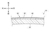
- FIG. 2 is a schematic view showing a cross section AA ′ of the window member 10 in FIG. 1 according to the first embodiment.
- the window member 10 is mounted on the upper part of the back door 2 above the rear combination lamp 3 of the back door 2 to form a rear window.
- the window member 10 represents a member that constitutes a transparent (or smoked) portion (window portion) so that the inside of the vehicle can be viewed from inside or outside the vehicle.
- the window member 10 is configured as a laminate including a resin base 20 and a silicone-based polymer hard coat layer 30 formed on the base 20.
- the base 20 is a plate-like member that is made of a polycarbonate resin and that is smoothly curved.
- the hard coat layer 30 has higher abrasion resistance than the substrate 20 and is formed along a gentle surface of the substrate 20.
- a protective layer 40 is formed on the hard coat layer 30 in the inner portion of the outer surface of the window member 10.
- the protective layer 40 is made of a film containing silicon dioxide (silica) as a main component, and has higher scratch resistance than the hard coat layer 30.
- the protective layer 40 is divided into ten parts in the longitudinal direction (the left-right direction in this example) of the hard coat layer 30 and divided into four parts in the short direction (the vertical direction in this example) to form a lattice (FIG. 1).
- the hard coat layer 30 is exposed at the location 50 where the protective layer 40 is divided (FIG. 2). As shown in FIG. 2, the protective layer 40 is formed on the gentle surface of the hard coat layer 30.
- the protective layer 40 is a film formed on the hard coat layer 30 by plasma enhanced chemical vapor deposition (CVD).
- CVD plasma enhanced chemical vapor deposition
- a method for forming the protective layer 40 will be described.
- the member provided with the mask is stored in a plasma CVD apparatus, and a raw material gas of silica is put into a plasma state to deposit a film containing silica as a main component on the hard coat layer 30. Thereafter, the member is taken out of the plasma CVD apparatus, and the mask is removed. According to this procedure, the divided protective layer 40 can be formed.
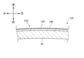
- FIG. 3 is a schematic view showing a cross section A-A ′ of the window member 110 in FIG. 1 according to the second embodiment.
- the window member 110 according to the second embodiment has the same configuration as the window member 10 according to the first embodiment except that the hard coat layer 130 and the protective layer 140 are different. Are denoted by the same reference numerals, and detailed description is omitted.
- the window member 110 is mounted on the upper part of the back door 2 above the rear combination lamp 3 of the back door 2 to form a rear window.
- the window member 110 is configured as a laminate including the base 20 and a hard coat layer 130 of a silicone-based polymer formed on the base 20.
- the hard coat layer 130 has higher abrasion resistance than the substrate 20 and is formed along the gentle surface of the substrate 20.
- a protective layer 140 is formed on the hard coat layer 130 in an inner portion of the outer surface of the window member 110.
- the protective layer 140 is made of a film containing silicon dioxide (silica) as a main component, and has higher scratch resistance than the hard coat layer 130.
- the protective layer 140 is formed in a lattice shape by being divided into ten parts in the longitudinal direction (the left-right direction in this example) and four parts in the short direction (the vertical direction in this example) of the hard coat layer 130 (FIG. 1).
- the hard coat layer 130 is exposed at the location 150 where the protective layer 140 is divided (FIG. 3).
- the protective layer 140 is formed on the concave portion on the surface of the hard coat layer.
- the protective layer 140 is a film formed by modifying the hard coat layer 130 of a silicone polymer by irradiation with ultraviolet rays. Specifically, the protective layer 140 is formed by irradiating the silicone-based polymer with ultraviolet rays, cutting the polymer-bonded chain (Si-C bonded chain), and recombining oxygen atoms and silicon atoms. Further, it is a film containing silicon dioxide as a main component.
- a method for forming the protective layer 140 will be described.
- masks having a predetermined width extending in the longitudinal direction and the lateral direction are provided at predetermined intervals.
- the member provided with the mask is irradiated with ultraviolet rays using a Xe 2 excimer lamp or the like in a nitrogen gas atmosphere to modify the silicone polymer. Thereafter, the mask is removed from the member. According to this procedure, the divided protective layer 140 can be formed.
- the thickness of the hard coat layer 130 irradiated with ultraviolet rays by this method is slightly smaller than that of the original hard coat layer 130 because the organic groups in the silicone-based polymer are removed and converted into silicon dioxide.
- the decreasing thickness is of the order of a few ⁇ m.
- a portion modified by irradiation with ultraviolet light is shown as one region, and is described as the protective layer 140.
- the ultraviolet light attenuates. Less reforming. That is, the boundary between the protective layer 140 and the hard coat layer 130 is not clearly formed, and the boundary line in FIG. 3 is illustrated for convenience.
- the base 20 in the first embodiment and the second embodiment can be manufactured by a method such as injection molding.
- the hard coat layer 130 in the first embodiment and the second embodiment is formed by applying a silicone-based polymer material to the substrate 20 by a wet method, for example, a dip coating method, and then drying the material at room temperature for a predetermined time. It can be formed on the substrate 20 by curing and drying by heating for a predetermined time.
- the protective layer on the surface of the hard coat layer formed on the substrate has a lower coefficient of linear expansion than the substrate. Therefore, in a large-sized member such as a window member for a vehicle, there is a high possibility that cracks (cracks) occur in the protective layer due to expansion and contraction of the base due to heat.
- the protective layers 40 and 140 divided at least into two in the longitudinal direction of the hard coat layers 30 and 130 are formed.
- the hard coat layers 30 and 130 are exposed at locations 50 and 150 where the protective layers 40 and 140 are divided. That is, the protective layers 40 and 140 obtained by dividing the hard coat layers 30 and 130 having a relatively higher linear expansion coefficient than the base 20 are connected to each other. Thereby, the force acting in the longitudinal direction of the protective layers 40 and 140 due to the expansion and contraction of the base 20 due to heat is buffered by the hard coat layers 30 and 130, and the occurrence of cracks can be suppressed.
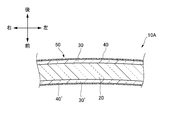
- FIG. 4 is a diagram illustrating a modified example of the window member 10 according to the first embodiment.
- the hard coat layer 30 ′ and the protective layer 40 ′ formed on the inside of the vehicle have lower abrasion resistance required than the hard coat layer 30 and the protective layer 40 formed on the outside of the vehicle.
- the material does not need to be the same as that described above, and a material having low scratch resistance may be selected. Further, only the hard coat layer 30 'may be formed without forming the protective layer 40' on the vehicle inner side.
- the protective layers 40 and 140 are divided into at least two in the longitudinal direction and at least two in the lateral direction of the hard coat layers 30 and 130. Are formed.
- the hard coat layers 30 and 130 are exposed at portions 15 and 150 where the protective layers 40 and 140 are divided.
- the protective layers 40 and 140 are divided into at least two in the longitudinal direction and at least two in the lateral direction, and are connected by the hard coat layers 30 and 130 having a relatively high linear expansion coefficient as compared with the base 20.
- the forces acting on the protective layers 40 and 140 in the longitudinal and transverse directions are buffered by the expansion and contraction of the base 20 due to the heat, so that the occurrence of cracks can be suitably suppressed.
- the divided protective layers 40 and 140 are provided at intervals of 10 nm or more and 1 mm or less. If an interval of 10 nm or more is formed, the force acting on the protective layers 40 and 140 due to the expansion and contraction of the base 20 can be suitably buffered. With an interval of 1 mm or less, it is possible to suppress sand particles or the like from hitting the hard coat layers 30 and 130, and it is possible to preferably prevent the window members 10 and 110 from being damaged.
- each of the divided protective layers 40 and 140 is preferably formed with an area of 0.01 mm 2 or more and 100 mm 2 or less. If it is formed with an area of 0.01 mm 2 or more, it is possible to suitably prevent the window members 10 and 110 from being damaged. Further, the area of 100 mm 2 is smaller than the area surrounded by cracks generated when the window member on which the undivided protective layer is formed is subjected to the severe heat resistance test, and is not more than the area. Thus, the occurrence of cracks in the protective layers 40 and 140 can be suitably suppressed.
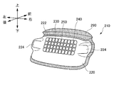
- FIG. 5 is a view showing a resin composite rear module 210 for a vehicle mounted on a rear portion of the vehicle.
- the composite rear module 210 is formed in a size that can cover the opening at the rear of the vehicle.
- the composite rear module 210 has a clear member 220 and a coloring member 290.
- the clear member 220 is a colorless transparent or colored transparent member.
- the clear member 220 has a pair of left and right lamp portions 224 that transmit light, and a window portion 222.
- the lamp part 224 is a part that transmits light emitted from a lamp member mounted on the vehicle or the composite rear module 210 itself to the outside of the vehicle.
- the window portion 222 is a portion that is colorless and transparent or smoked (an example of colored and transparent) so that the inside of the vehicle can be viewed from inside or outside the vehicle.
- the clear member 220 has a three-dimensional surface.
- the coloring member 290 is a member having a lower light transmittance than the clear member 220.
- the coloring member 290 is colored so as to shield at least a part of the inside of the vehicle from the outside.
- the coloring member 290 is provided on the front side of the clear member 220, and is provided along the periphery of the clear member 220.
- the clear member 220 and the coloring member 290 are made of resin and are made of polycarbonate.
- the coloring member 290 is made of a material in which a coloring material is kneaded with a resin material to be a base. Further, the coloring member may contain an additive such as a filler.
- a hard coat layer 230 of a silicone-based polymer is provided on the rear surface of the clear member 220 on the rear side of the vehicle to prevent the clear member 220 from being damaged.
- the hard coat layer 230 has better scratch resistance than the clear member 220.
- a protective layer 240 is formed on a surface of the hard coat layer 230 behind the vehicle.
- the protective layer 240 is formed on the window 222 of the clear member 220.
- the protective layer 240 is made of a film containing silicon dioxide (silica) as a main component, and has better scratch resistance than the hard coat layer 230.
- the protective layer 240 is formed in a lattice shape by being divided into ten parts in the longitudinal direction (the left-right direction in this example) of the window part 222 and four parts in the short direction (the vertical direction in this example) (FIG. 5). ).
- the hard coat layer 230 is exposed at a location 250 where the protective layer 240 is divided (FIG. 5). Note that, as described in the first and second embodiments, the protective layer 240 is formed on the gentle surface of the hard coat layer 230 (see FIG. 2), or It is formed on the concave portion on the surface of the layer 230 (see FIG. 3).
- the method described in the first embodiment and the second embodiment can be adopted. That is, a method of depositing silicon dioxide on the hard coat layer 230 by plasma CVD, a method of irradiating the hard coat layer 230 with ultraviolet rays to modify the silicone polymer and form a film containing silicon dioxide as a main component, and the like. Can be adopted.
- a resin member including the clear member 220 and the coloring member 290 is produced by two-color molding using injection compression molding, and the produced resin member is wet-processed, for example.
- a hard coat layer material is applied by a dip coating method, dried at room temperature for a predetermined time, and then hardened and dried by heating for a predetermined time to produce a hard coat layer.
- the protective layer 240 is divided into at least two in the longitudinal direction of the window 222.
- the hard coat layer 230 is exposed at the division 250 of the protective layer 240. That is, the hard coat layer 230 having a higher linear expansion coefficient than the base (clear member 220) connects the divided protective layers 240 to each other. Accordingly, the force acting in the longitudinal direction of the protective layer 240 due to the expansion and contraction of the base (clear member 220) due to heat is buffered by the hard coat layer 230, and the occurrence of cracks can be suppressed.
- the example in which the hard coat layer 230 and the protective layer 240 are formed on one surface (outside of the vehicle) of the window 222 is shown.
- a hard coat layer and a protective layer may be formed inside the window part 222 (inside the vehicle) according to the third embodiment.
- the protective layer 240 that is divided into at least two in the longitudinal direction of the window 222 and at least two in the lateral direction is formed.
- the hard coat layer 230 is exposed at a location 250 where each of the protective layers 240 is divided.
- the protective layer 240 is divided into at least two parts in the longitudinal direction and at least two parts in the lateral direction, and is connected by the hard coat layer 230 having a higher linear expansion coefficient than the base (clear member 220).
- the force acting in the longitudinal direction and the lateral direction of the protective layer 240 is buffered by the expansion and contraction of the clear member 220) due to the heat, and the occurrence of cracks can be suitably suppressed.
- the divided protective layers 240 are provided at intervals of 10 nm or more and 1 mm or less. If an interval of 10 nm or more is formed, the force acting on the protective layer 240 due to expansion and contraction of the base (clear member 220) can be suitably buffered. With an interval of 1 mm or less, it is possible to prevent sand particles or the like from hitting the hard coat layer 230, and it is possible to preferably prevent the window 222 from being damaged.
- each of the divided protective layers 240 is preferably formed with an area of 0.01 mm 2 or more and 100 mm 2 or less. If it is formed with an area of 0.01 mm 2 or more, scratches on the window 222 can be suitably suppressed.
- the area of 100 mm 2 is smaller than the area surrounded by cracks generated when the resin member having the undivided protective layer 240 formed on the surface is subjected to a severe heat resistance test, and is equal to or less than the area. By doing so, generation of cracks in the protective layer 240 can be suitably suppressed.
- split refers to the protective layer 40.
- 140, and 240 are not strictly divided into two areas.
- the portions 50, 150, 250 where the hard coat layers 30, 130, 230 are exposed between the protective layers 40, 140, 240 do not extend to the ends of the protective layers 40, 140, 240.
- the case where the portions 50, 150, 250 where the hard coat layers 30, 130, 230 extending linearly are exposed are intermittently configured is also included.
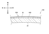
- FIG. 6 is a diagram illustrating another modified example of the window member 10 according to the first embodiment. As shown in FIG. 6, a mode in which the thin protective layer 40 ⁇ / b> B slightly adheres to the portion 50 ⁇ / b> B of the window member 10 ⁇ / b> B where the hard coat layer 30 is exposed is also referred to as “split” in the present disclosure. It is included in the aspect.
- the term “exposed” does not only refer to the case where the protective layers 40, 140, 240 are not formed at all on the hard coat layers 30, 130, 230, but a slightly thin film. (See FIG. 6) in which the protective layers 40, 140, and 240 are formed.
- the divisions 50, 150, and 250 may be in the middle of the hard coat layers 30, 130 or the window 222 in the longitudinal direction. And not necessarily.
- the middle gap between the hard coat layers 30 and 130 or the window 222 extends in the transverse direction at the center of the center portion when the hard coat layers 30 and 130 or the window 222 are equally divided in the longitudinal direction, for example. At least one gap is assumed.
- the window members 10 and 110 constituting the rear window have been described.
- the present disclosure is not limited to this, and the front window and other vehicle window members may be used. Therefore, it is also applicable to resin-made products.
- the composite rear module 210 has been described.
- the present disclosure is not limited to this, and is a composite front module, or another composite module for a vehicle, which is made of a resin having at least a window. It is also applicable to things.
- the shape of the hard coat layer of the window member and the window of the composite module in plan view is not particularly limited, and may be, for example, substantially rectangular or elliptical.
- an arbitrary direction may be determined as the length and the width. In this case, since the substrate is divided into at least two in any direction, a force acting in the longitudinal direction of the protective layer due to expansion and contraction of the base by heat is buffered by the hard coat layer.
- the phrase “divided” does not only mean that the protective layer is strictly divided equally, but also includes a case where the protective layer is divided unevenly.
- a primer layer such as an acrylic resin may be provided between the substrate and the hard coat layer in consideration of the difference in adhesion and linear expansion coefficient between the substrate and the hard coat layer.
- a composite rear module having a lamp portion that transmits light from a lamp member has been described.
- the lamp member for example, a stop lamp, a turn signal lamp, a back lamp, a tail lamp, a rear fog lamp, a daytime Lamps and the like.
- a rear combination lamp composed of any combination of these lamps may be used.
- the composite module of the present disclosure may include members such as a lamp, a cleaner, a wiper, a sensor, and a defogger.
- the lamp include those described above.
- the sensor include LiDAR, camera, radar, and the like.
- the base 20, 120 and the clear member 220 are made of polycarbonate.
- the base may be made of a transparent resin material such as an acrylic resin or a polyolefin resin. Is also good.
- polycarbonate it is preferable to use polycarbonate from the viewpoints of moldability, transparency, light weight, impact resistance and the like.
Landscapes
- Engineering & Computer Science (AREA)
- Mechanical Engineering (AREA)
- Laminated Bodies (AREA)
Abstract
樹脂製の基体(20)と、基体(20)の上に形成されたシリコーン系ポリマーのハードコート層(30)と、を備える車両用の樹脂製窓部材(10)であって、ハードコート層(30)の上に保護層(40)が形成されており、保護層(40)が、ハードコート層(30)の長手方向において少なくとも二分割されていて、保護層(40)が分割されている箇所(50)においてハードコート層(30)が露出している、車両用の樹脂製窓部材(10)。
Description
本発明は、車両用の樹脂製窓部材および車両用の樹脂製複合モジュールに関する。
特許文献1には、樹脂基板の少なくとも一方の面に、アクリル樹脂の第1層と、オルガノシロキサン硬化物の第2層と、プラズマを併用した真空成膜プロセスにより形成される二酸化珪素の第3層がこの順に積層された、樹脂積層体が開示されている。
ところで、車両には常に軽量化が求められている。車両の軽量化の手段として、樹脂により車両用の窓部材を形成することが検討されている。一方で、樹脂製の窓部材は、ガラス製のものと比較して耐擦傷性が弱い傾向にある。車両用の窓部材の少なくとも一定の耐擦傷性が要求される部分に、ハードコート層を形成することで耐擦傷性を向上させることができる。また、ハードコート層の表面に保護層を形成することにより、耐擦傷性をさらに向上させることができる。
しかしながら、樹脂製の基体上に形成されたハードコート層の表面の保護層は、基体と比較して線膨張係数が低い。そのため、車両用の窓部材のような大型の部材においては、熱による基体の伸縮によって、当該保護層にひび割れ(クラック)が生じる可能性がある。
そこで本発明は、クラックの発生を抑制できる車両用の樹脂製窓部材および車両用の樹脂製複合モジュールを提供することを目的とする。
上記目的を達成するために、本発明の車両用の樹脂製窓部材は、
樹脂製の基体と、前記基体の上に形成されたシリコーン系ポリマーのハードコート層と、を備える車両用の樹脂製窓部材であって、
前記ハードコート層の上に保護層が形成されており、
前記保護層が、前記ハードコート層の長手方向において少なくとも二分割されていて、前記保護層が分割されている箇所において前記ハードコート層が露出している。
樹脂製の基体と、前記基体の上に形成されたシリコーン系ポリマーのハードコート層と、を備える車両用の樹脂製窓部材であって、
前記ハードコート層の上に保護層が形成されており、
前記保護層が、前記ハードコート層の長手方向において少なくとも二分割されていて、前記保護層が分割されている箇所において前記ハードコート層が露出している。
当該車両用の樹脂製窓部材によれば、基体の熱による伸縮により保護層の長手方向に働く力が、ハードコート層により緩衝され、クラックの発生を抑制できる。
また、上記の車両用の樹脂製窓部材は、
前記保護層が、前記ハードコート層の長手方向において少なくとも三分割されていると好ましい。
前記保護層が、前記ハードコート層の長手方向において少なくとも三分割されていると好ましい。
また、上記の車両用の樹脂製窓部材は、
前記保護層が、前記ハードコート層の短手方向において少なくとも二分割されていると好ましい。
前記保護層が、前記ハードコート層の短手方向において少なくとも二分割されていると好ましい。
また、上記の車両用の樹脂製窓部材は、
分割された保護層が10nm以上1mm以下の間隔で設けられていると好ましい。
分割された保護層が10nm以上1mm以下の間隔で設けられていると好ましい。
また、上記の車両用の樹脂製窓部材は、
分割された保護層の各々が0.01mm2以上100mm2以下の面積で形成されていると好ましい。
分割された保護層の各々が0.01mm2以上100mm2以下の面積で形成されていると好ましい。
また、上記目的を達成するために、本発明の車両用の樹脂製複合モジュールは、
三次元形状の表面を有する樹脂製の基体と、前記基体の上に形成されたシリコーン系ポリマーのハードコート層と、を備え、少なくとも窓部を有する、車両用の樹脂製複合モジュールであって、
前記ハードコート層の上に保護層が形成されており、
前記保護層が、少なくとも前記窓部に形成されており、
前記保護層が、前記窓部の長手方向において少なくとも二分割されており、
前記保護層が分割されている箇所において前記ハードコート層が露出している。
三次元形状の表面を有する樹脂製の基体と、前記基体の上に形成されたシリコーン系ポリマーのハードコート層と、を備え、少なくとも窓部を有する、車両用の樹脂製複合モジュールであって、
前記ハードコート層の上に保護層が形成されており、
前記保護層が、少なくとも前記窓部に形成されており、
前記保護層が、前記窓部の長手方向において少なくとも二分割されており、
前記保護層が分割されている箇所において前記ハードコート層が露出している。
当該車両用の樹脂製複合モジュールによれば、基体の熱による伸縮により保護層の長手方向に働く力が、ハードコート層により緩衝され、クラックの発生を抑制できる。
本発明によれば、クラックの発生を抑制できる車両用の樹脂製窓部材および車両用の樹脂製複合モジュールを提供することができる。
以下、図面を参照しつつ本発明の実施形態について詳細に説明する。尚、本図面に示された各部材の寸法は、説明の便宜上、実際の各部材の寸法とは異なる場合がある。
また、本実施形態の説明では、説明の便宜上、「上下方向」、「前後方向」、「左右方向」について適宜言及する。これらの方向は、図1または図5の車両について設定された相対的な方向である。ここで、「上下方向」は、「上方向」及び「下方向」を含む方向である。「前後方向」は、「前方向」及び「後方向」を含む方向である。「左右方向」は、「左方向」及び「右方向」を含む方向である。
(車両用の樹脂製窓部材)
まず、図1および図2を参照して、第一の実施形態に係る車両用の樹脂製窓部材を説明する。図1は、車両用の樹脂製窓部材10を備えるハッチバック式の車両1の後部を示す図である。図2は、第一の実施形態に係る図1における窓部材10のA-A’断面を示す模式図である。
まず、図1および図2を参照して、第一の実施形態に係る車両用の樹脂製窓部材を説明する。図1は、車両用の樹脂製窓部材10を備えるハッチバック式の車両1の後部を示す図である。図2は、第一の実施形態に係る図1における窓部材10のA-A’断面を示す模式図である。
図1に示す車両1において、窓部材10はバックドア2のリアコンビランプ3よりも上側の、バックドア2の上部に搭載されて、リアウインドウを構成している。ここで、窓部材10とは、車内から車外または車外から車内を視認可能なように透明またはスモークとされる部分(窓部)を構成する部材を表す。図2に示すように、窓部材10は、樹脂製の基体20と、基体20の上に形成されたシリコーン系ポリマーのハードコート層30と、を備える積層体として構成されている。基体20は、ポリカーボネート樹脂で構成されて、なだらかに湾曲した板状の部材である。ハードコート層30は、基体20よりも耐擦傷性が高く、基体20のなだらかな表面に沿って形成されている。
窓部材10の車外側の表面の内側部分において、ハードコート層30の上に保護層40が形成されている。保護層40は、二酸化珪素(シリカ)を主成分とする膜により構成されており、ハードコート層30よりも耐擦傷性が高い。保護層40は、ハードコート層30の長手方向(本例では左右方向)において10分割され、また短手方向(本例では上下方向)において4分割されて、格子状に形成されている(図1)。保護層40が分割されている箇所50においてハードコート層30が露出している(図2)。図2に示すように、保護層40はハードコート層30のなだらかな面の上に形成されている。
保護層40は、プラズマ化学蒸着(CVD)によって、ハードコート層30の上に形成された膜である。ここで、保護層40の形成方法について説明する。基体20と、基体20の上に形成されたハードコート層30と、を備える部材のハードコート層30の上に、長手方向及び短手方向に延びる所定の幅のマスクを所定の間隔で設ける。マスクが設けられた当該部材をプラズマCVD装置に格納し、シリカの原料ガスをプラズマ状態にして、シリカを主成分とする膜をハードコート層30の上に堆積させる。その後、当該部材をプラズマCVD装置から取出し、マスクを外す。この手順により、分割された保護層40を形成できる。
続いて、図1および図3を参照して、第二の実施形態に係る車両用の樹脂製窓部材110を説明する。図3は、第二の実施形態に係る図1における窓部材110のA-A’断面を示す模式図である。なお、第二の実施形態に係る窓部材110は、ハードコート層130および保護層140が異なる以外は、第一の実施形態に係る窓部材10と同様の構成であるため、これら以外の構成については同じ符号を付し、詳細な説明を省略する。
図1に示す車両1において、窓部材110はバックドア2のリアコンビランプ3よりも上側の、バックドア2の上部に搭載されて、リアウインドウを構成している。図3に示すように、窓部材110は、基体20と、基体20の上に形成されたシリコーン系ポリマーのハードコート層130と、を備える積層体として構成されている。ハードコート層130は、基体20よりも耐擦傷性が高く、基体20のなだらかな表面に沿って形成されている。
窓部材110の車外側の表面の内側部分において、ハードコート層130の上に保護層140が形成されている。保護層140は、二酸化珪素(シリカ)を主成分とする膜により構成されており、ハードコート層130よりも耐擦傷性が高い。保護層140は、ハードコート層130の長手方向(本例では左右方向)において10分割され、また短手方向(本例では上下方向)において4分割されて、格子状に形成されている(図1)。保護層140が分割されている箇所150においてハードコート層130が露出している(図3)。図3に示すように、保護層140はハードコート層130の表面の凹部の上に形成されている。
保護層140は、シリコーン系ポリマーのハードコート層130を紫外線照射により改質して形成された膜である。具体的には、保護層140は、シリコーン系ポリマーに紫外線を照射して、高分子の結合鎖(Si-C結合鎖)を切断し、酸素原子とケイ素原子とを再結合させることで形成された、二酸化珪素を主成分とする膜である。ここで、保護層140の形成方法について説明する。基体20と、基体20の上に形成されたハードコート層130と、を備える部材のハードコート層130の上に、長手方向及び短手方向に延びる所定の幅のマスクを所定の間隔で設ける。マスクが設けられた当該部材に、窒素ガス雰囲気下でXe2エキシマランプ等を用いて紫外線を照射して、シリコーン系ポリマーを改質させる。その後、当該部材からマスクを外す。この手順により、分割された保護層140を形成できる。
当該方法により紫外線を照射されたハードコート層130では、シリコーン系ポリマー中の有機基が抜けて二酸化珪素に変換されるため、元のハードコート層130よりも若干厚みが減少している。減少する厚みは、数μm程度である。なお、図3では紫外線が照射されて改質された部分を一つの領域として図示し、保護層140として説明しているが、実際にはハードコート層130の表面から遠ざかるほど、紫外線が減衰して改質があまりされなくなる。すなわち、保護層140とハードコート層130との境界が明確に形成されるものではなく、図3における前記境界の線は便宜上図示しているものである。
第一の実施形態および第二の実施形態における基体20は、射出成形等の方法で作製することができる。また、第一の実施形態および第二の実施形態におけるハードコート層130は、基体20に湿式法、例えばディップコート法によりシリコーン系ポリマー原料を塗布して、所定時間、室温にて乾燥させた後、所定時間、加熱により硬化乾燥させて基体20上に形成することができる。
ところで、基体に形成されたハードコート層の表面の保護層は、基体と比較して線膨張係数が低い。そのため、車両用の窓部材のような大型の部材においては、熱による基体の伸縮によって、保護層にひび割れ(クラック)が生じる可能性が高い。
第一の実施形態および第二の実施形態に係る窓部材10,110では、ハードコート層30,130の長手方向において少なくとも二分割された保護層40,140が形成されている。そして、保護層40,140が分割されている箇所50,150において、ハードコート層30,130が露出している。すなわち、基体20と比較して線膨張係数が比較的高いハードコート層30,130が分割された保護層40,140同士をつなげている。これにより、基体20の熱による伸縮により保護層40,140の長手方向に働く力が、ハードコート層30,130により緩衝され、クラックの発生を抑制できる。
また、第一の実施形態および第二の実施形態では、ハードコート層30,130および保護層40,140が窓部材10,110の一方の面(車外側)に形成さている例を示したが、図4に示すように窓部材10Aの内側(車内側)にもハードコート層30’および保護層40’を形成しても良い。図4は、第一の実施形態に係る窓部材10の変形例を示す図である。この場合、車内側に形成されるハードコート層30’及び保護層40’は、車外側に形成されるハードコート層30及び保護層40よりも要求される耐擦傷性が低いため、必ずしも車外側と同種の材料である必要はなく、耐擦傷性の低い材料を選択してもよい。また、車内側で保護層40’が形成されずにハードコート層30’のみが形成されていてもよい。
また、第一の実施形態および第二の実施形態に係る窓部材10,110では、ハードコート層30,130の長手方向において少なくとも二分割、短手方向において少なくとも二分割された保護層40,140が形成されている。そして、保護層40,140が分割されている箇所15,150において、ハードコート層30,130が露出している。保護層40,140が長手方向において少なくとも二分割、短手方向において少なくとも二分割されて、基体20と比較して線膨張係数が比較的高いハードコート層30,130によりつなげられていることで、基体20の熱による伸縮により保護層40,140の長手方向および短手方向に働く力が緩衝され、クラックの発生を好適に抑制できる。
また、第一の実施形態および第二の実施形態において、分割された保護層40,140が10nm以上1mm以下の間隔で設けられていると好ましい。10nm以上の間隔が形成されていれば、基体20の伸縮により保護層40,140に働く力を好適に緩衝できる。1mm以下の間隔であれば、砂粒等がハードコート層30,130にぶつかることを抑制でき、窓部材10,110の傷付きを好適に抑制できる。
また、第一の実施形態および第二の実施形態において、分割された保護層40,140の各々が0.01mm2以上100mm2以下の面積で形成されていると好ましい。0.01mm2以上の面積で形成されていれば、窓部材10,110の傷付きを好適に抑制できる。また、100mm2の面積は、分割されていない保護層が形成された窓部材を苛酷耐熱性試験にかけた際に生じたクラックで囲まれた面積よりも小さい面積であり、当該面積以下とすることで、保護層40,140のクラックの発生を好適に抑制することができる。
(車両用の樹脂製複合モジュール)
続いて、図5を参照して、第三の実施形態に係る車両用の樹脂製複合モジュールを説明する。図5は、車両の後部に搭載される車両用の樹脂製複合リアモジュール210を示す図である。複合リアモジュール210は、車両の後部の開口を覆うことができる大きさで形成されている。
続いて、図5を参照して、第三の実施形態に係る車両用の樹脂製複合モジュールを説明する。図5は、車両の後部に搭載される車両用の樹脂製複合リアモジュール210を示す図である。複合リアモジュール210は、車両の後部の開口を覆うことができる大きさで形成されている。
複合リアモジュール210は、クリア部材220と着色部材290とを有している。クリア部材220は、無色透明または有色透明の部材である。クリア部材220は、光を透過させる左右一対のランプ部224と、窓部222とを有している。ランプ部224は、車両または複合リアモジュール210自体に搭載されたランプ部材から出射される光を車両の外に透過する部分である。窓部222は、車内から車外または車外から車内を視認可能なように無色透明またはスモーク(有色透明の一例)とされる部分である。クリア部材220は三次元形状の表面を有している。
着色部材290は、クリア部材220と比べて光の透過率が低い部材である。着色部材290は、少なくとも車両の内部の一部を外部から遮蔽するように、着色されている。着色部材290はクリア部材220よりも前方側に設けられ、クリア部材220の周りに沿うように設けられている。クリア部材220及び着色部材290は樹脂製であり、ポリカーボネートで構成される。着色部材290は母体となる樹脂材料に着色材料が混練された材料で構成されている。また、着色部材はフィラー等の添加材を含有してもよい。
クリア部材220の車両の後方の表面にはクリア部材220の傷つきを抑制するためのシリコーン系ポリマーのハードコート層230が設けられている。ハードコート層230は、クリア部材220よりも耐擦傷性が優れている。ハードコート層230の車両の後方の表面には、保護層240が形成されている。保護層240はクリア部材220の窓部222に形成されている。保護層240は、二酸化珪素(シリカ)を主成分とする膜により構成されており、ハードコート層230よりも耐擦傷性が優れている。保護層240は、窓部222の長手方向(本例では左右方向)において10分割され、また短手方向(本例では上下方向)において4分割されて、格子状に形成されている(図5)。保護層240が分割されている箇所250においてハードコート層230が露出している(図5)。なお、上記の第一の実施形態および第二の実施形態で説明したように、保護層240はハードコート層230のなだらかな面の上に形成されている(図2参照)か、またはハードコート層230の表面の凹部の上に形成されている(図3参照)。
分割された保護層240を複合リアモジュール210に形成する方法としては、上記の第一の実施形態および第二の実施形態で説明した方法を採用し得る。すなわち、プラズマCVDにより二酸化珪素をハードコート層230の上に堆積させる方法、ハードコート層230に紫外線を照射してシリコーン系ポリマーを改質し二酸化珪素を主成分とする膜を形成する方法等を採用し得る。なお、保護層240を形成する前の部材は、射出圧縮成形を用いた二色成形によって、クリア部材220と着色部材290とを備える樹脂部材を作製し、作成された樹脂部材に湿式法、例えばディップコート法によりハードコート層原料を塗布して、所定時間、室温にて乾燥させた後、所定時間、加熱により硬化乾燥させて作製される。
第三の実施形態に係る複合リアモジュール210では、保護層240が窓部222の長手方向において少なくとも二分割されている。そして、保護層240の分割されている箇所250において、ハードコート層230が露出している。すなわち、基体(クリア部材220)と比較して線膨張係数が高いハードコート層230が分割された保護層240同士をつなげている。これにより、基体(クリア部材220)の熱による伸縮により保護層240の長手方向に働く力が、ハードコート層230により緩衝され、クラックの発生を抑制できる。
また、第三の実施形態では、ハードコート層230および保護層240が窓部222の一方の面(車外側)に形成されている例を示したが、図4の第一の実施形態に係る窓部材10の変形例で示したように、第三の実施形態に係る窓部222の内側(車内側)にもハードコート層および保護層を形成しても良い。
また、第三の実施形態に係る複合リアモジュール210では、窓部222の長手方向において少なくとも二分割、短手方向において少なくとも二分割された保護層240が形成されている。そして、それぞれの保護層240が分割されている箇所250において、ハードコート層230が露出している。保護層240が長手方向において少なくとも二分割、短手方向において少なくとも二分割されて、基体(クリア部材220)と比較して線膨張係数が高いハードコート層230によりつなげられていることで、基体(クリア部材220)の熱による伸縮により保護層240の長手方向および短手方向に働く力が緩衝され、クラックの発生を好適に抑制できる。
また、第三の実施形態において、分割された保護層240が10nm以上1mm以下の間隔で設けられていると好ましい。10nm以上の間隔が形成されていれば、基体(クリア部材220)の伸縮により保護層240に働く力を好適に緩衝できる。1mm以下の間隔であれば、砂粒等がハードコート層230にぶつかることを抑制でき、窓部222の傷付きを好適に抑制できる。
また、第三の実施形態において、分割された保護層240の各々が0.01mm2以上100mm2以下の面積で形成されていると好ましい。0.01mm2以上の面積で形成されていれば、窓部222の傷付きを好適に抑制できる。また、100mm2の面積は、分割されていない保護層240が表面に形成された樹脂部材を苛酷耐熱性試験にかけた際に生じたクラックで囲まれた面積よりも小さい面積であり、当該面積以下とすることで、保護層240のクラックの発生を好適に抑制することができる。
第一の実施形態~第三の実施形態において、「分割されている」保護層40,140,240の特定の態様を説明したが、本開示において「分割されている」とは、保護層40,140,240が厳密に2領域に分けられている場合のみを指すわけではない。例えば、保護層40,140,240同士の間のハードコート層30,130,230が露出している箇所50,150,250が、保護層40,140,240の端部まで伸びていない場合も含む。また、直線状に延びるハードコート層30,130,230が露出している箇所50,150,250が間欠的に構成されている場合も含む。また、各保護層40,140,240の間が完全に分割されていなくても、ハードコート層30,130,230が露出している箇所50,150,250の部分に、薄膜状の保護層40,140,240がわずかに付着している状態も含む。図6は、第一の実施形態に係る窓部材10の別の変形例を示す図である。図6に示すような、窓部材10Bのハードコート層30が露出している箇所50Bの部分に、薄膜状の保護層40Bがわずかに付着している態様も、本開示における「分割されている」態様に含まれる。また、本開示において「露出している」という用語は、ハードコート層30,130,230上に保護層40,140,240が全く形成されていない場合のみを指すわけではなく、わずかに薄膜状の保護層40,140,240が形成されている態様も含む(図6)。
また、本開示において、保護層40,140,240が二分割されている場合の分割箇所50,150,250は、ハードコート層30,130または窓部222の長手方向の真ん中であってもよいし、そうでなくてもよい。ハードコート層30,130または窓部222の真ん中の隙間としては、例えばハードコート層30,130または窓部222を長手方向においてそれぞれ三等分した場合の、中央部分の中間において短手方向に延びる少なくとも一本の隙間が想定される。
また、第一の実施形態および第二の実施形態において、リアウインドウを構成する窓部材10,110を説明したが、本開示はこれに限定されず、フロントウインドウ、その他の車両用の窓部材であって樹脂製のものにも適用可能である。また、第三の実施形態において、複合リアモジュール210を説明したが、本開示はこれに限定されず、複合フロントモジュール、その他の車両用の複合モジュールであって、少なくとも窓部を備える樹脂製のものにも適用可能である。
また、本開示において、窓部材におけるハードコート層、複合モジュールにおける窓部の平面視における形状は特に限定されるものではなく、例えば略矩形であってもよく、楕円形状であってもよい。ハードコート層または窓部における長手と短手とが同じ長さとなる場合は、任意の方向を長手と短手と決定してもよい。この場合には、いずれかの方向において少なくとも二分割されていることで、基体の熱による伸縮により保護層の長手方向に働く力が、ハードコート層により緩衝される。
また、本開示において、長手方向又は短手方向に分割されているという場合、厳密に長手方向又は短手方向に直交する隙間が形成されている場合のみを指すわけではなく、長手方向又は短手方向に対して斜めに隙間が形成されている場合も含む。また、「分割されている」という場合、厳密に保護層が等分されている場合のみを指すわけではなく不均一に分割されている場合も含む。
以上特定の態様を例示したが、本発明は、上述した実施形態に限定されず、適宜、変形、改良等が自在である。その他、上述した実施形態における各構成要素の材質、形状、寸法、数値、形態、数、配置場所等は、本発明を達成できるものであれば任意であり、限定されない。
例えば、本開示において、基体とハードコート層との間の密着性や線膨張係数の差を考慮して、基体とハードコート層との間に、アクリル系樹脂等のプライマー層を設けてもよい。
例えば第三の実施形態において、ランプ部材の光を透過するランプ部を有する複合リアモジュールを説明したが、ランプ部材としては、例えばストップランプ、ターンシグナルランプ、バックランプ、テールランプ、リアフォグランプ、デイタイムランプ等が挙げられる。また、これらのランプの任意の組合せから構成されるリアコンビネーションランプでもよい。
また、本開示の複合モジュールには、ランプ、クリーナー、ワイパー、センサ、デフォッガー等の部材が搭載されていてもよい。ランプとしては例えば上記で説明したものが挙げられる。またセンサとしては例えばLiDAR、カメラ、レーダ等が挙げられる。
また、上記の実施形態において、基体20,120およびクリア部材220がポリカーボネートで構成される態様を説明したが、この他にもアクリル系樹脂、ポリオレフィン系樹脂等の透明樹脂材料で基体を構成しても良い。ただし、成形性、透明性、軽量性、耐衝撃性等の観点から、ポリカーボネートを用いることが好ましい。
なお、本願は、2018年8月27日付で出願された日本国特許出願(特願2018-158491)に基づいており、その全体が引用により援用される。また、ここに引用されるすべての参照は全体として取り込まれる。
1:車両、10,10A,10B,110:窓部材、20,120:基体、30,30’,130,230:ハードコート層、40,40’,40B,140,240:保護層、50,50B,150,250:箇所、210:複合リアモジュール、220:クリア部材、222:窓部
Claims (6)
- 樹脂製の基体と、前記基体の上に形成されたシリコーン系ポリマーのハードコート層と、を備える車両用の樹脂製窓部材であって、
前記ハードコート層の上に保護層が形成されており、
前記保護層が、前記ハードコート層の長手方向において少なくとも二分割されていて、前記保護層が分割されている箇所において前記ハードコート層が露出している、車両用の樹脂製窓部材。 - 前記保護層が、前記ハードコート層の長手方向において少なくとも三分割されている、請求項1に記載の樹脂製窓部材。
- 前記保護層が、前記ハードコート層の短手方向において少なくとも二分割されている、請求項1に記載の樹脂製窓部材。
- 分割された保護層が10nm以上1mm以下の間隔で設けられている、請求項1に記載の樹脂製窓部材。
- 分割された保護層の各々が0.01mm2以上100mm2以下の面積で形成されている、請求項1に記載の樹脂製窓部材。
- 三次元形状の表面を有する樹脂製の基体と、前記基体の上に形成されたシリコーン系ポリマーのハードコート層と、を備え、少なくとも窓部を有する、車両用の樹脂製複合モジュールであって、
前記ハードコート層の上に保護層が形成されており、
前記保護層が、少なくとも前記窓部に形成されており、
前記保護層が、前記窓部の長手方向において少なくとも二分割されており、
前記保護層が分割されている箇所において前記ハードコート層が露出している、
車両用の樹脂製複合モジュール。
Priority Applications (2)
| Application Number | Priority Date | Filing Date | Title |
|---|---|---|---|
| CN201980055972.1A CN112638677A (zh) | 2018-08-27 | 2019-06-05 | 车辆用的树脂制窗部件以及车辆用的树脂制复合模块 |
| JP2020540074A JPWO2020044705A1 (ja) | 2018-08-27 | 2019-06-05 | 車両用の樹脂製窓部材および車両用の樹脂製複合モジュール |
Applications Claiming Priority (2)
| Application Number | Priority Date | Filing Date | Title |
|---|---|---|---|
| JP2018-158491 | 2018-08-27 | ||
| JP2018158491 | 2018-08-27 |
Publications (1)
| Publication Number | Publication Date |
|---|---|
| WO2020044705A1 true WO2020044705A1 (ja) | 2020-03-05 |
Family
ID=69644078
Family Applications (1)
| Application Number | Title | Priority Date | Filing Date |
|---|---|---|---|
| PCT/JP2019/022309 Ceased WO2020044705A1 (ja) | 2018-08-27 | 2019-06-05 | 車両用の樹脂製窓部材および車両用の樹脂製複合モジュール |
Country Status (3)
| Country | Link |
|---|---|
| JP (1) | JPWO2020044705A1 (ja) |
| CN (1) | CN112638677A (ja) |
| WO (1) | WO2020044705A1 (ja) |
Cited By (1)
| Publication number | Priority date | Publication date | Assignee | Title |
|---|---|---|---|---|
| WO2024024613A1 (ja) | 2022-07-26 | 2024-02-01 | 信越化学工業株式会社 | 被覆物品およびその製造方法 |
Citations (3)
| Publication number | Priority date | Publication date | Assignee | Title |
|---|---|---|---|---|
| JPS54121964U (ja) * | 1978-02-14 | 1979-08-25 | ||
| JP2002520205A (ja) * | 1998-07-15 | 2002-07-09 | アグフア−ゲヴエルト,ナームローゼ・フエンノートシヤツプ | 区分されたガラスラミネート |
| JP2017137031A (ja) * | 2016-02-05 | 2017-08-10 | イビデン株式会社 | 自動車用セキュリティー対応樹脂ガラス及びセキュリティーシステム |
Family Cites Families (2)
| Publication number | Priority date | Publication date | Assignee | Title |
|---|---|---|---|---|
| JP2004196008A (ja) * | 2002-12-16 | 2004-07-15 | Toyota Motor Corp | 樹脂製自動車ウィンドウおよびその製造方法 |
| JP6770683B2 (ja) * | 2016-11-17 | 2020-10-21 | Agc株式会社 | 車両用樹脂製枠体付き板状体 |
-
2019
- 2019-06-05 JP JP2020540074A patent/JPWO2020044705A1/ja active Pending
- 2019-06-05 CN CN201980055972.1A patent/CN112638677A/zh active Pending
- 2019-06-05 WO PCT/JP2019/022309 patent/WO2020044705A1/ja not_active Ceased
Patent Citations (3)
| Publication number | Priority date | Publication date | Assignee | Title |
|---|---|---|---|---|
| JPS54121964U (ja) * | 1978-02-14 | 1979-08-25 | ||
| JP2002520205A (ja) * | 1998-07-15 | 2002-07-09 | アグフア−ゲヴエルト,ナームローゼ・フエンノートシヤツプ | 区分されたガラスラミネート |
| JP2017137031A (ja) * | 2016-02-05 | 2017-08-10 | イビデン株式会社 | 自動車用セキュリティー対応樹脂ガラス及びセキュリティーシステム |
Cited By (2)
| Publication number | Priority date | Publication date | Assignee | Title |
|---|---|---|---|---|
| WO2024024613A1 (ja) | 2022-07-26 | 2024-02-01 | 信越化学工業株式会社 | 被覆物品およびその製造方法 |
| KR20250044665A (ko) | 2022-07-26 | 2025-04-01 | 신에쓰 가가꾸 고교 가부시끼가이샤 | 피복 물품 및 그 제조 방법 |
Also Published As
| Publication number | Publication date |
|---|---|
| JPWO2020044705A1 (ja) | 2021-08-26 |
| CN112638677A (zh) | 2021-04-09 |
Similar Documents
| Publication | Publication Date | Title |
|---|---|---|
| JP6494241B2 (ja) | 二色成形品 | |
| JP2014511285A (ja) | レーダー透過性を有するコーティング | |
| WO2009110152A1 (ja) | 透明樹脂板及びその製造方法 | |
| CN112317271A (zh) | 透明的车辆零件的制造方法 | |
| KR20120123357A (ko) | 하드 코트층을 갖는 수지 기판의 제조 방법 및 하드 코트층을 갖는 수지 기판 | |
| WO2020044705A1 (ja) | 車両用の樹脂製窓部材および車両用の樹脂製複合モジュール | |
| JP5308064B2 (ja) | 反射防止樹脂とその製造方法 | |
| CN207350139U (zh) | 用于机动车大灯的遮盖盘片、车辆大灯和车辆 | |
| CN109530189B (zh) | 车辆用的树脂制复合组件及其制造方法 | |
| US11635186B2 (en) | Polymeric substrate and a method of providing same | |
| CN112781006A (zh) | 透明车辆部件的制造方法 | |
| JP6434350B2 (ja) | 輸送機器用風防表面の改質方法 | |
| US20190093858A1 (en) | Vehicle lens assembly and lens manufacturing method | |
| JP6799990B2 (ja) | レーダカバーの製造方法 | |
| JP2016030392A (ja) | ハードコート層付き樹脂基板およびハードコート層付き樹脂基板の製造方法 | |
| US10367330B2 (en) | Diffuser, laser-light-source module using the same, and method for manufacturing the same | |
| JP6032152B2 (ja) | 車体と合成樹脂製積層パネルとの接着構造 | |
| CN113518714B (zh) | 车辆用的树脂制部件 | |
| US11305312B2 (en) | Method for manufacturing a transparent vehicle part | |
| US11867942B1 (en) | Encapsulated illuminated automotive glazing and method of producing thereof | |
| WO2021095649A1 (ja) | 樹脂成形品、車窓用樹脂成形品、及び、樹脂成形品の製造方法 | |
| JP6842761B2 (ja) | 樹脂ガラス板及びその製造方法 | |
| JP2020032759A (ja) | 車両用の樹脂製複合モジュールの製造方法 | |
| JP2005310386A (ja) | 車両用灯具の反射鏡 | |
| WO2021112116A1 (ja) | 樹脂成形品、車窓用樹脂成形品、および、樹脂成形品の製造方法 |
Legal Events
| Date | Code | Title | Description |
|---|---|---|---|
| 121 | Ep: the epo has been informed by wipo that ep was designated in this application |
Ref document number: 19854512 Country of ref document: EP Kind code of ref document: A1 |
|
| ENP | Entry into the national phase |
Ref document number: 2020540074 Country of ref document: JP Kind code of ref document: A |
|
| NENP | Non-entry into the national phase |
Ref country code: DE |
|
| 122 | Ep: pct application non-entry in european phase |
Ref document number: 19854512 Country of ref document: EP Kind code of ref document: A1 |