WO2020044401A1 - エレベータドアの安全装置 - Google Patents
エレベータドアの安全装置 Download PDFInfo
- Publication number
- WO2020044401A1 WO2020044401A1 PCT/JP2018/031557 JP2018031557W WO2020044401A1 WO 2020044401 A1 WO2020044401 A1 WO 2020044401A1 JP 2018031557 W JP2018031557 W JP 2018031557W WO 2020044401 A1 WO2020044401 A1 WO 2020044401A1
- Authority
- WO
- WIPO (PCT)
- Prior art keywords
- door
- elevator door
- panel
- link member
- contact member
- Prior art date
- Legal status (The legal status is an assumption and is not a legal conclusion. Google has not performed a legal analysis and makes no representation as to the accuracy of the status listed.)
- Ceased
Links
Images


Classifications
-
- B—PERFORMING OPERATIONS; TRANSPORTING
- B66—HOISTING; LIFTING; HAULING
- B66B—ELEVATORS; ESCALATORS OR MOVING WALKWAYS
- B66B13/00—Doors, gates, or other apparatus controlling access to, or exit from, cages or lift well landings
- B66B13/24—Safety devices in passenger lifts, not otherwise provided for, for preventing trapping of passengers
- B66B13/26—Safety devices in passenger lifts, not otherwise provided for, for preventing trapping of passengers between closing doors
Definitions
- the present invention relates to an elevator door safety device in which a contact member is movably provided on an elevator door via a link member.
- an elevator door device in which an obstacle detector is provided at a door stop side end of a door panel via two link members.
- two mounting shafts are mounted on a door panel via mounting hardware.
- Link members are individually and rotatably mounted on the two mounting shafts. When the obstacle sensor moves with respect to the door panel, each link member rotates about each mounting axis according to the movement of the obstacle sensor (for example, see Patent Document 1).
- the mounting bracket and the mounting shaft are arranged on the inner side in the width direction of the door panel than the range in which the obstacle detector moves. For this reason, the space inside the width direction of the door panel cannot be effectively utilized. For example, when a window is provided on a door panel, when the window is large, at least a part of the mounting bracket and the mounting shaft are visible from the outside through the window, and the design of the door panel is deteriorated.
- the present invention has been made to solve the above-described problems, and has as its object to provide an elevator door safety device capable of reducing an installation space for an elevator door.
- the safety device for an elevator door includes a first mounting shaft and a second mounting shaft which are provided on the elevator door and which are vertically separated from each other, and protrude from a door stop side end of the elevator door.
- a contact member movable between the position and the retracted position located closer to the door pocket than the projecting position, the contact member being movable with respect to the elevator door, the contact member, and the first mounting shaft, in accordance with the movement of the contact member with respect to the elevator door.
- a first link member, a contact member, and a second mounting shaft that rotate about the first mounting shaft, and rotate about the second mounting shaft in response to movement of the contact member with respect to the elevator door.
- a link member and a switch for detecting whether the contact member has deviated from the protruding position When the contact member is viewed along the thickness direction of the elevator door, the elevator door First mounting shaft and the second mounting shaft is disposed within the contact member moves relative to.
- the installation space of the safety device for the elevator door can be reduced.
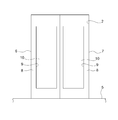
- FIG. 1 is a front view showing an elevator door device according to Embodiment 1 of the present invention.
- FIG. 2 is a sectional view taken along the line II-II in FIG. 1.
- FIG. 3 is a sectional view taken along the line III-III of FIG. 1. It is a front view which shows the elevator door apparatus when it sees from the inside of the car of FIG.
- FIG. 1 is a front view showing an elevator door device according to Embodiment 1 of the present invention.
- a car 1 is provided in a hoistway so as to be movable in a vertical direction.
- the car 1 is provided with a car doorway 2 as an elevator doorway.
- a hanger case 3 arranged above the car entrance 2 and a car sill 5 arranged below the car entrance 2 are fixed to the car 1.
- FIG. 1 shows the elevator door device when viewed from the outside of the car 1.
- the door rail 4 disposed along the frontage of the car doorway 2 is fixed to the hanger case 3.
- a first car door 6 and a second car door 7 are suspended from the door rail 4.
- Each of the first car door 6 and the second car door 7 is an elevator door that opens and closes the car entrance 2.
- the first car door 6 and the second car door 7 are movable along the door rail 4 in the direction of the frontage of the car entrance 2.
- the hanger case 3 is provided with a door driving device (not shown).
- the first car door 6 and the second car door 7 move in opposite directions along the frontage direction of the car entrance 2 by the driving force of the door driving device.
- the car doorway 2 is opened and closed by the movement of the first car door 6 and the second car door 7. Therefore, the elevator door device according to the present embodiment is a double door type elevator door device.
- the end located on the front side in the traveling direction of the first car door 6 when closing the car entrance 2 is the door stop side end of the first car door 6.
- the end of the first car door 6 that is located on the front side in the traveling direction of the first car door 6 when opening the car doorway 2 is the end of the first car door 6 on the door pocket side.
- the end located on the front side in the traveling direction of the second car door 7 when closing the car entrance 2 is the door stop side end of the second car door 7.
- the end located on the front side in the traveling direction of the second car door 7 when the car entrance 2 is opened is the door pocket side end of the second car door 7. .
- the car sill 5 is arranged along the frontage of the car doorway 2.
- a sill groove (not shown) is provided in the car sill 5 along the moving direction of the first car door 6 and the second car door 7.
- Each of the first car door 6 and the second car door 7 includes a door panel 8 for opening and closing the car doorway 2, a door hanger 11 provided at an upper end of the door panel 8, and a plurality of legs provided at a lower end of the door panel 8.
- the door hangers 11 of the first car door 6 and the second car door 7 are hung on the door rail 4. Each leg of the first car door 6 and the second car door 7 is inserted into a sill groove of the car sill 5.
- each door panel 8 of the first car door 6 and the second car door 7 matches the frontage direction of the car entrance 2.
- the height direction of each door panel 8 of the first car door 6 and the second car door 7 coincides with the height direction of the car entrance 2.
- the thickness direction of each door panel 8 of the first car door 6 and the second car door 7 coincides with the depth direction of the car entrance 2.
- Each of the door panels 8 of the first car door 6 and the second car door 7 is provided with an opening 9 as a door window.
- the respective shapes of the door panel 8 and the opening 9 are rectangular.
- the width dimension of the opening 9 is larger than half the width dimension of the door panel 8.
- the position of the opening 9 with respect to the door panel 8 is closer to the door stop side end of the door panel 8 than the door pocket side end of the door panel 8.
- a window plate 10 for closing the opening 9 is provided on each door panel 8 of the first car door 6 and the second car door 7.
- the window plate 10 is a transparent plate made of glass.
- FIG. 2 is a cross-sectional view taken along the line II-II of FIG.
- FIG. 3 is a sectional view taken along line III-III in FIG.
- the door panels 8 of the first car door 6 and the second car door 7 respectively extend from the panel front plate 81 provided with the opening 9 and both ends in the width direction of the panel front plate 81 to the back side of the panel front plate 81. It has a pair of panel end plates 82 that protrude, and a pair of panel return plates 83 that protrude inward in the width direction of the door panel 8 from each of the pair of panel end plates 82.
- One panel end plate 82 of the door panel 8 forms an end face in the width direction of the door panel 8 at the door stop side end of the door panel 8.
- the other panel end plate 82 of the door panel 8 forms an end face in the width direction of the door panel 8 at the door pocket side end of the door panel 8.
- the first car door 6 is provided with a safety device 21 as shown in FIG.
- the safety device 21 includes a safety shoe 22, a first link device 23, a second link device 24, a spring 25, a switch 26, and a stopper 27.
- a part of the safety shoe 22 is omitted to show a configuration hidden by the safety shoe 22.
- the safety shoe 22 is a rod-shaped contact member arranged along the height direction of the first car door 6.
- the safety shoe 22 is arranged within a range in the height direction of the door panel 8 of the first car door 6. Further, the safety shoe 22 is movable with respect to the first car door 6 between a projecting position projecting from the door stop side end of the first car door 6 and a retracted position located closer to the door pocket than the projecting position. It has become. Thereby, when the safety shoe 22 reaches the projecting position, a part of the safety shoe 22 projects outward in the width direction of the door panel 8 of the first car door 6. When in the retracted position, the safety shoe 22 is located outside the opening 9 in the width direction of the first car door 6. Thereby, even if the safety shoe 22 reaches the retreat position, the safety shoe 22 is not exposed to the outside through the opening 9.
- FIG. 1 shows a state in which the safety shoe 22 is at the projecting position.
- the first link device 23 and the second link device 24 are vertically separated from each other.
- the second link device 24 is disposed below the first link device 23.
- each of the first link device 23 and the second link device 24 is disposed between the widthwise end surface of the door panel 8 and the opening 9 at the door stop side end of the first car door 6.
- the first link device 23 has a first fixing plate 231, a first mounting shaft 232, a first link member 233, and a first connection mechanism 234.
- the first fixing plate 231 is fixed to the back surface of the panel front plate 81 of the first car door 6.
- the first mounting shaft 232 is fixed to the first fixing plate 231.
- the first mounting shaft 232 is provided on the door panel 8 of the first car door 6 via the first fixing plate 231.
- the axis of the first mounting shaft 232 is orthogonal to the panel front plate 81 of the first car door 6.
- the axial direction of the first mounting shaft 232 matches the thickness direction of the door panel 8 of the first car door 6.
- the first link member 233 is attached to the safety shoe 22 and the first attachment shaft 232. One end of the first link member 233 is rotatably attached to the first attachment shaft 232. Thereby, the first link member 233 rotates about the first mounting shaft 232 in accordance with the movement of the safety shoe 22 with respect to the first car door 6.
- the first mounting shaft 232 and the first link member 233 are arranged within a range of the panel end plate 82 in the thickness direction of the door panel 8 of the first car door 6. Thereby, even when the first car door 6 is viewed along any of the width direction and the thickness direction of the first car door 6, the first mounting shaft 232 and the first link member 233 are connected to the first car door 6. It is housed inside the door panel 8 of the car door 6.
- the first connection mechanism 234 is a mechanism for attaching the safety shoe 22 to the other end of the first link member 233. That is, the safety shoe 22 is attached to the other end of the first link member 233 via the first connection mechanism 234.
- the first connection mechanism 234 includes a first connection shaft 235, a first support member 236, and a first coupler 237.
- the first connection shaft 235 is rotatably provided at the other end of the first link member 233.
- the axis of the first connection shaft 235 is parallel to the axis of the first mounting shaft 232.
- the safety shoe 22 is provided with a groove 221 extending in the longitudinal direction of the safety shoe 22.
- a protrusion 222 is provided on the inner surface of the groove 221.
- the first support member 236 is a U-shaped member having a pair of arms parallel to each other and a connecting portion connecting ends of the pair of arms.
- the first support member 236 is arranged with the U-shaped opening facing outward in the width direction of the door panel 8.
- One arm of the first support member 236 is fixed to an end of the first connection shaft 235.
- the other arm of the first support member 236 is inserted into the groove 221 of the safety shoe 22.
- the first coupler 237 has a screw that can be inserted into the groove 221 of the safety shoe 22.
- the other arm of the first support member 236 is attached to the protrusion 222 in the groove 221 by tightening a screw of the first coupling tool 237.
- the first connection shaft 235 overlaps the safety shoe 22 when the safety shoe 22 is viewed along the thickness direction of the first car door 6.
- the safety shoe 22 is rotatable about the first connection shaft 235 with respect to the first link member 233.
- the first connection shaft 235 moves with respect to the first car door 6 in accordance with the movement of the safety shoe 22 with respect to the first car door 6.
- the first connection shaft 235 is located below the first attachment shaft 232 and closer to the door pocket than the first attachment shaft 232, as shown in FIG. are doing.
- the second link device 24 has a second fixing plate 241, a second mounting shaft 242, a second link member 243, and a second connection mechanism 244.
- the second fixing plate 241 is fixed to the back surface of the panel front plate 81 of the first car door 6.
- the second mounting shaft 242 is fixed to the second fixing plate 241.
- the second mounting shaft 242 is provided on the door panel 8 of the first car door 6 via the second fixing plate 241.
- the axis of the second mounting shaft 242 is parallel to the axis of the first mounting shaft 232. Therefore, the axial direction of the second mounting shaft 242 matches the thickness direction of the door panel 8 of the first car door 6.
- the second link member 243 is attached to the safety shoe 22 and the second attachment shaft 242. One end of the second link member 243 is rotatably attached to the second attachment shaft 242. Thereby, the second link member 243 rotates about the second mounting shaft 242 in accordance with the movement of the safety shoe 22 with respect to the first car door 6.
- the second mounting shaft 242 and the second link member 243 are arranged within the range of the panel end plate 82 in the thickness direction of the door panel 8 of the first car door 6. Thereby, when the first car door 6 is viewed along any of the width direction and the thickness direction of the first car door 6, the second mounting shaft 242 and the second link member 243 are moved to the first car door 6. It is housed inside the door panel 8 of the car door 6.
- the second connection mechanism 244 is a mechanism for attaching the safety shoe 22 to the other end of the second link member 243. That is, the safety shoe 22 is attached to the other end of the second link member 243 via the second connection mechanism 244.
- the second connection mechanism 244 includes a second connection shaft 245, a second support member 246, and a second coupler 247.
- the second connection shaft 245 is rotatably provided at the other end of the second link member 243. Further, the axis of the second connection shaft 245 is parallel to the axis of the second mounting shaft 242.
- the second support member 246 is a U-shaped member having a pair of arms parallel to each other and a connecting portion that connects ends of the pair of arms.
- the second support member 246 is arranged with the U-shaped opening facing outward in the width direction of the door panel 8.
- One arm of the second support member 246 is fixed to an end of the second connection shaft 245.
- the other arm of the second support member 246 is inserted into the groove 221 of the safety shoe 22.
- the second coupling tool 247 has a screw that can be inserted into the groove 221 of the safety shoe 22.
- the other arm of the second support member 246 is attached to the protrusion 222 in the groove 221 by tightening a screw of the second coupling tool 247.
- the second connection shaft 245 overlaps the safety shoe 22 when the safety shoe 22 is viewed along the thickness direction of the first car door 6.
- the safety shoe 22 is rotatable about the second connection shaft 245 with respect to the second link member 243.
- the second connection shaft 245 moves with respect to the first car door 6 in accordance with the movement of the safety shoe 22 with respect to the first car door 6.
- the second connection shaft 245 is located below the second attachment shaft 242 and closer to the door pocket than the second attachment shaft 242, as shown in FIG. are doing.
- the first mounting shaft 232, the second mounting shaft 242, the first link member 233, and the second link member 243 form a first position when the safety shoe 22 is viewed along the thickness direction of the first car door 6.
- the safety shoe 22 is disposed within a range in which the safety shoe 22 moves with respect to the one car door 6. Thereby, when the safety shoe 22 is viewed along the thickness direction of the first car door 6 when the safety shoe 22 is located at least at any position within the movement range of the safety shoe 22, the safety shoe 22
- the first mounting shaft 232, the second mounting shaft 242, the first link member 233, and the second link member 243 overlap.
- the safety shoe 22 when the safety shoe 22 is viewed along the thickness direction of the first car door 6, the safety shoe 22 is located at a position overlapping the safety shoe 22 regardless of the position between the protruding position and the retracted position.
- a first mounting shaft 232, a second mounting shaft 242, a first link member 233, and a second link member 243 are arranged.
- the first link member 233 and the second link member 243 are linked to the movement of the safety shoe 22 with respect to the first car door 6 while keeping the state parallel to each other. Thereby, the safety shoe 22 moves between the protruding position and the retracted position while keeping the longitudinal direction of the safety shoe 22 up and down.
- the spring 25 is an elastic body connected to the first fixing plate 231 and the first link member 233, as shown in FIG.
- the spring 25 generates an elastic restoring force between the first fixing plate 231 and the first link member 233.
- the spring 25 applies a force to the first link member 233 such that the first link member 233 rotates counterclockwise in FIG. 1 around the first mounting shaft 232. That is, the spring 25 applies a force to the first link member 233 in a direction in which the safety shoe 22 moves to the protruding position.
- the switch 26 is attached to the second fixed plate 241.
- the switch 26 is arranged at a position operated by the second link member 243 when the safety shoe 22 is at the projecting position. Further, the state in which the switch 26 is operated by the second link member 243 is released when the safety shoe 22 is displaced from the projecting position to the retracted position.
- the switch 26 detects whether or not the safety shoe 22 has deviated from the projecting position by detecting whether or not it has been operated by the second link member 243. For example, when the safety shoe 22 is pushed from the projecting position to the retracted position by an obstacle while the first car door 6 is moving, the state in which the switch 26 is operated by the second link member 243 is released.
- the car 1 is provided with a door control device (not shown) for controlling the movement of each of the first car door 6 and the second car door 7.
- the switch 26 sends a detection signal to the door control device by detecting that the safety shoe 22 has deviated from the projecting position.
- the door control device controls the movement of each of the first car door 6 and the second car door 7 based on whether or not a detection signal has been received from the switch 26.
- the stopper 27 is fixed to the second fixing plate 241.
- the stopper 27 receives the second link member 243 when the safety shoe 22 is at the protruding position.
- the stopper 27 prevents the second link member 243 from rotating counterclockwise in FIG. That is, by receiving the first link member 243, the stopper 27 prevents the safety shoe 22 from moving from the projecting position in the direction opposite to the retracted position.
- FIG. 4 is a front view showing the elevator door device when viewed from the inside of the car 1 in FIG.
- the car doorway 2 is closed by the first car door 6 and the second car door 7, when viewed from the inside of the car 1, the respective openings 9 of the first car door 6 and the second car door 7 have the car doorway. It fits inside 2.
- the safety shoe 22, the first link device 23, the second link device 24, the spring 25, the switch 26, and the stopper 27 are hidden from the door panel 8 without protruding from the opening 9 when viewed from the inside of the car 1. .
- the operation will be described. Normally, the position of the safety shoe 22 is maintained at the protruding position by the weight of the safety shoe 22 and the elastic restoring force of the spring 25. When the safety shoe 22 is in the protruding position, the switch 26 is operated by the second link member 243. Thus, the first car door 6 and the second car door 7 perform a normal opening / closing operation under the control of the door control device.
- the second link member is formed.
- the operation state of the switch 26 by 243 is released.
- the detection signal is sent from the switch 26 to the door control device.
- the door control device Upon receiving the detection signal from the switch 26, the door control device performs control to reverse the moving direction of the first car door 6 and the second car door 7 from the door closing direction to the door opening direction.
- the first mounting shaft when the safety shoe 22 is viewed along the thickness direction of the first car door 6, the first mounting shaft is within a range in which the safety shoe 22 moves with respect to the first car door 6. 232 and a second mounting shaft 242 are arranged. Therefore, the first mounting shaft 232 and the second mounting shaft 242 can be accommodated within the range in which the safety shoe 22 moves. Thereby, the dimension of the installation space of the safety device 21 in the width direction of the first car door 6 can be reduced. Thereby, the installation space of the safety device 21 with respect to the first car door 6 can be reduced. Therefore, for example, when the opening 9 is provided as a door window in the door panel 8 of the first car door 6, the opening 9 is enlarged while maintaining the design without exposing the safety device 21 from the opening 9. be able to.
- the first connection shaft 235 is located below the first attachment shaft 232 and closer to the door pocket than the first attachment shaft 232 when the safety shoe 22 is at the projecting position.
- the second connection shaft 245 is located below the second attachment shaft 242 and closer to the door pocket than the second attachment shaft 242 when the safety shoe 22 is at the projecting position. Therefore, a moment due to the weight of the safety shoe 22 due to its own weight can be applied to the first link member 233 and the second link member 243 in the direction in which the safety shoe 22 moves to the projecting position. Thereby, the position of the safety shoe 22 can be easily maintained at the projecting position, and occurrence of a malfunction due to the safety shoe 22 accidentally coming off the projecting position can be suppressed.
- the first link member 233 and the second link member 243 are arranged within the range of the panel end plate 82 in the thickness direction of the door panel 8 of the first car door 6. Therefore, each of the first link member 233 and the second link member 243 can be accommodated inside the first car door 6 in the thickness direction. Thereby, it is possible to prevent the safety device 21 from being disposed so as to protrude greatly behind the first car door 6. Accordingly, it is possible to prevent the safety device 21 from coming out to the landing side from the end surface of the car sill 5 on the landing side.
- a sensor having a light emitter and a light receiver that receives light from the light emitter may be added to the safety device 21.
- an obstacle such as a passenger passing through the car doorway 2 can be detected in a non-contact manner.
- an obstacle can be more reliably detected.
- one of the light emitter and the light receiver is provided on the safety shoe 22.
- the other device is arranged at a position facing one device in the moving direction of the first car door 6 and the second car door 7.
- the light receiver when the light projector is provided on the safety shoe 22, the light receiver is arranged at a position facing the light projector in the moving direction of the first car door 6 and the second car door 7. In this case, the light receiver is provided at the door stop side end of the door panel 8 of the second car door 7.
- the sensor detects that there is an obstacle between the light emitter and the light receiver when the state in which the light from the light emitter is received by the light receiver is stopped.
- the sensor for example, an infrared sensor that receives infrared light emitted from a light emitter by a light receiver is used.
- the light receiver may be provided on the safety shoe 22.
- the light projector is arranged at a position facing the light receiver in the moving direction of the first car door 6 and the second car door 7. That is, the floodlight is provided at the door stop side end of the door panel 8 of the second car door 7.
- the safety device 21 is provided on the first car door 6.
- the safety device 21 may be provided on the second car door 7.
- the safety device 21 is provided in the double door type elevator door device in which the first car door 6 and the second car door 7 move in opposite directions when the car doorway 2 is opened and closed.
- the safety device 21 may be provided in a single-opening elevator door device in which the first car door 6 and the second car door 7 move in the same direction when opening and closing the car entrance 2.
- first car door (elevator door), 7 second car door (elevator door), 8 door panel, 22 safety shoe (contact member), 81 panel top plate, 82 panel end plate, 232 first mounting shaft, 233 second No. 1 link member, 235 # first connection shaft, 242 # second mounting shaft, 243 # second link member, 245 # second connection shaft.
Landscapes
- Elevator Door Apparatuses (AREA)
Abstract
エレベータドアの安全装置において、接触部材は、エレベータドアの戸当たり側端部から突出する突出位置と、突出位置よりも戸袋側に位置する退避位置との間でエレベータドアに対して移動可能になっている。エレベータドアには、第1の取付軸及び第2の取付軸が設けられている。第1のリンク部材は、接触部材及び第1の取付軸に取り付けられている。第2のリンク部材は、接触部材及び第2の取付軸に取り付けられている。エレベータドアの厚さ方向に沿って接触部材を見たとき、エレベータドアに対して接触部材が移動する範囲内に第1の取付軸及び第2の取付軸が配置されている。
Description
この発明は、エレベータドアに接触部材がリンク部材を介して移動可能に設けられたエレベータドアの安全装置に関するものである。
従来、ドアパネルの戸当たり側端部に2つのリンク部材を介して障害物感知体が設けられたエレベータドア装置が知られている。このような従来のエレベータドア装置では、2つの取付軸が取付金具を介してドアパネルに取り付けられている。2つの取付軸には、リンク部材が個別に回転自在に取り付けられている。障害物感知体がドアパネルに対して移動すると、障害物感知体の移動に応じて各リンク部材が各取付軸を中心に回転する(例えば特許文献1参照)。
特許文献1に示されている従来のエレベータドア装置では、取付金具及び取付軸が、障害物感知体が移動する範囲よりもドアパネルの幅方向内側に配置されている。このため、ドアパネルの幅方向内側のスペースを有効に活用することができなくなってしまう。例えば、ドアパネルに窓が設けられている場合、窓が大きくなると、取付金具及び取付軸の少なくとも一部が窓を通して外部から見えてしまい、ドアパネルの意匠性が低下してしまう。
この発明は、上記のような課題を解決するためになされたものであり、エレベータドアに対する設置スペースの縮小化を図ることができるエレベータドアの安全装置を得ることを目的とする。
この発明によるエレベータドアの安全装置は、エレベータドアに設けられ、上下方向へ互いに離して配置されている第1の取付軸及び第2の取付軸、エレベータドアの戸当たり側端部から突出する突出位置と、突出位置よりも戸袋側に位置する退避位置との間でエレベータドアに対して移動可能な接触部材、接触部材及び第1の取付軸に取り付けられ、エレベータドアに対する接触部材の移動に応じて第1の取付軸を中心に回転する第1のリンク部材、接触部材及び第2の取付軸に取り付けられ、エレベータドアに対する接触部材の移動に応じて第2の取付軸を中心に回転する第2のリンク部材、及び接触部材が突出位置から外れたか否かを検出するスイッチを備え、エレベータドアの厚さ方向に沿って接触部材を見たとき、エレベータドアに対して接触部材が移動する範囲内に第1の取付軸及び第2の取付軸が配置されている。
この発明によるエレベータドアの安全装置によれば、エレベータドアに対する安全装置の設置スペースの縮小化を図ることができる。
以下、この発明の実施の形態について図面を参照して説明する。
実施の形態1.
図1は、この発明の実施の形態1によるエレベータドア装置を示す正面図である。図において、昇降路内には、かご1が上下方向へ移動可能に設けられている。かご1には、エレベータ出入口としてのかご出入口2が設けられている。また、かご1には、かご出入口2の上方に配置されたハンガケース3と、かご出入口2の下部に配置されたかご敷居5とが固定されている。なお、図1では、かご1の外側から見たときのエレベータドア装置が示されている。
実施の形態1.
図1は、この発明の実施の形態1によるエレベータドア装置を示す正面図である。図において、昇降路内には、かご1が上下方向へ移動可能に設けられている。かご1には、エレベータ出入口としてのかご出入口2が設けられている。また、かご1には、かご出入口2の上方に配置されたハンガケース3と、かご出入口2の下部に配置されたかご敷居5とが固定されている。なお、図1では、かご1の外側から見たときのエレベータドア装置が示されている。
ハンガケース3には、かご出入口2の間口方向に沿って配置されたドアレール4が固定されている。ドアレール4には、第1かごドア6及び第2かごドア7が吊り下げられている。第1かごドア6及び第2かごドア7のそれぞれは、かご出入口2を開閉するエレベータドアである。
第1かごドア6及び第2かごドア7は、かご出入口2の間口方向へドアレール4に沿って移動可能になっている。ハンガケース3には、図示しないドア駆動装置が設けられている。第1かごドア6及び第2かごドア7は、ドア駆動装置の駆動力によってかご出入口2の間口方向に沿って互いに反対方向へ移動する。かご出入口2は、第1かごドア6及び第2かごドア7の移動により開閉される。従って、本実施の形態によるエレベータドア装置は、両開き式のエレベータドア装置になっている。
第1かごドア6の幅方向両端部のうち、かご出入口2を閉じるときの第1かごドア6の進行方向前側に位置する端部は、第1かごドア6の戸当たり側端部である。また、第1かごドア6の幅方向両端部のうち、かご出入口2を開くときの第1かごドア6の進行方向前側に位置する端部は、第1かごドア6の戸袋側端部である。
第2かごドア7の幅方向両端部のうち、かご出入口2を閉じるときの第2かごドア7の進行方向前側に位置する端部は、第2かごドア7の戸当たり側端部である。また、第2かごドア7の幅方向両端部のうち、かご出入口2を開くときの第2かごドア7の進行方向前側に位置する端部は、第2かごドア7の戸袋側端部である。
かご敷居5は、かご出入口2の間口方向に沿って配置されている。かご敷居5には、図示しない敷居溝が第1かごドア6及び第2かごドア7の移動方向に沿って設けられている。
第1かごドア6及び第2かごドア7のそれぞれは、かご出入口2を開閉するドアパネル8と、ドアパネル8の上端部に設けられたドアハンガ11と、ドアパネル8の下端部に設けられた複数の脚とを有している。
第1かごドア6及び第2かごドア7のそれぞれのドアハンガ11は、ドアレール4に掛けられている。第1かごドア6及び第2かごドア7のそれぞれの脚は、かご敷居5の敷居溝に挿入されている。
第1かごドア6及び第2かごドア7のそれぞれのドアパネル8の幅方向は、かご出入口2の間口方向と一致している。また、第1かごドア6及び第2かごドア7のそれぞれのドアパネル8の高さ方向は、かご出入口2の高さ方向と一致している。さらに、第1かごドア6及び第2かごドア7のそれぞれのドアパネル8の厚さ方向は、かご出入口2の奥行き方向と一致している。
第1かごドア6及び第2かごドア7のそれぞれのドアパネル8には、ドア窓としての開口部9が設けられている。この例では、ドアパネル8及び開口部9のそれぞれの形状が矩形状になっている。また、この例では、開口部9の幅方向寸法がドアパネル8の幅方向寸法の半分よりも大きくなっている。さらに、この例では、ドアパネル8に対する開口部9の位置が、ドアパネル8の戸袋側端部よりもドアパネル8の戸当たり側端部に近い位置になっている。
第1かごドア6及び第2かごドア7のそれぞれのドアパネル8には、開口部9を塞ぐ窓板10が設けられている。窓板10は、ガラス製の透明な板である。
ここで、図2は、図1のII-II線に沿った断面図である。また、図3は、図1のIII-III線に沿った断面図である。第1かごドア6及び第2かごドア7のそれぞれのドアパネル8は、開口部9が設けられたパネル表板81と、パネル表板81の幅方向両端部のそれぞれからパネル表板81の裏側へ突出する一対のパネル端板82と、一対のパネル端板82のそれぞれからドアパネル8の幅方向内側へ突出する一対のパネル返し板83とを有している。
ドアパネル8における一方のパネル端板82は、ドアパネル8の戸当たり側端部におけるドアパネル8の幅方向端面を形成している。ドアパネル8における他方のパネル端板82は、ドアパネル8の戸袋側端部におけるドアパネル8の幅方向端面を形成している。
第1かごドア6には、図1に示すように、安全装置21が設けられている。安全装置21は、セーフティシュー22、第1リンク装置23、第2リンク装置24、ばね25、スイッチ26及びストッパ27を有している。なお、図1では、セーフティシュー22に隠れている構成を示すために、セーフティシュー22の一部を省略している。
セーフティシュー22は、第1かごドア6の高さ方向に沿って配置された棒状の接触部材である。セーフティシュー22は、第1かごドア6のドアパネル8の高さ方向の範囲内に配置されている。また、セーフティシュー22は、第1かごドア6の戸当たり側端部から突出する突出位置と、突出位置よりも戸袋側に位置する退避位置との間で第1かごドア6に対して移動可能になっている。これにより、セーフティシュー22が突出位置に達すると、セーフティシュー22の一部が第1かごドア6のドアパネル8の幅方向外側へ突出する。退避位置にあるときのセーフティシュー22は、開口部9よりも第1かごドア6の幅方向外側に位置している。これにより、セーフティシュー22が退避位置に達しても、セーフティシュー22が開口部9を通して外部に露出することはない。なお、図1には、セーフティシュー22が突出位置にあるときの状態が示されている。
第1リンク装置23及び第2リンク装置24は、上下方向へ互いに離して配置されている。この例では、第2リンク装置24が第1リンク装置23の下方に配置されている。また、第1リンク装置23及び第2リンク装置24のそれぞれは、第1かごドア6の戸当たり側端部におけるドアパネル8の幅方向端面と開口部9との間に配置されている。
第1リンク装置23は、図2に示すように、第1の固定板231、第1の取付軸232、第1のリンク部材233及び第1の接続機構234を有している。
第1の固定板231は、第1かごドア6のパネル表板81の裏面に固定されている。第1の取付軸232は、第1の固定板231に固定されている。これにより、第1の取付軸232は、第1の固定板231を介して第1かごドア6のドアパネル8に設けられている。
第1の取付軸232の軸線は、第1かごドア6のパネル表板81と直交している。これにより、第1の取付軸232の軸線方向は、第1かごドア6のドアパネル8の厚さ方向と一致している。
第1のリンク部材233は、セーフティシュー22及び第1の取付軸232に取り付けられている。第1のリンク部材233の一端部は、第1の取付軸232に回転自在に取り付けられている。これにより、第1のリンク部材233は、第1かごドア6に対するセーフティシュー22の移動に応じて第1の取付軸232を中心に回転する。
第1の取付軸232及び第1のリンク部材233は、第1かごドア6のドアパネル8の厚さ方向におけるパネル端板82の範囲内に配置されている。これにより、第1かごドア6の幅方向及び厚さ方向のいずれの方向に沿って第1かごドア6を見たときにも、第1の取付軸232及び第1のリンク部材233が第1かごドア6のドアパネル8の内側に収まっている。
第1の接続機構234は、第1のリンク部材233の他端部にセーフティシュー22を取り付ける機構である。即ち、セーフティシュー22は、第1の接続機構234を介して第1のリンク部材233の他端部に取り付けられている。
第1の接続機構234は、第1の接続軸235、第1の支持部材236及び第1の結合具237を有している。
第1の接続軸235は、第1のリンク部材233の他端部に回転自在に設けられている。また、第1の接続軸235の軸線は、第1の取付軸232の軸線と平行になっている。
セーフティシュー22には、セーフティシュー22の長手方向に沿った溝221が設けられている。溝221の内面には、突起部222が設けられている。
第1の支持部材236は、互いに平行な一対の腕部と、一対の腕部の端部同士を繋ぐ繋ぎ部とを有するU字状の部材である。第1の支持部材236は、U字状の開放部をドアパネル8の幅方向外側に向けて配置されている。
第1の支持部材236の一方の腕部は、第1の接続軸235の端部に固定されている。第1の支持部材236の他方の腕部は、セーフティシュー22の溝221に挿入されている。
第1の結合具237は、セーフティシュー22の溝221に挿入可能なねじを有している。第1の支持部材236の他方の腕部は、第1の結合具237のねじの締め付けによって溝221内の突起部222に取り付けられている。
第1の接続軸235は、第1かごドア6の厚さ方向に沿ってセーフティシュー22を見たとき、セーフティシュー22に重なっている。セーフティシュー22は、第1のリンク部材233に対して第1の接続軸235を中心に回転自在になっている。第1の接続軸235は、第1かごドア6に対するセーフティシュー22の移動に応じて第1かごドア6に対して移動する。また、第1の接続軸235は、セーフティシュー22が突出位置にあるとき、図1に示すように、第1の取付軸232よりも下方でかつ第1の取付軸232よりも戸袋側に位置している。
第2リンク装置24は、図3に示すように、第2の固定板241、第2の取付軸242、第2のリンク部材243及び第2の接続機構244を有している。
第2の固定板241は、第1かごドア6のパネル表板81の裏面に固定されている。第2の取付軸242は、第2の固定板241に固定されている。これにより、第2の取付軸242は、第2の固定板241を介して第1かごドア6のドアパネル8に設けられている。
第2の取付軸242の軸線は、第1の取付軸232の軸線と平行になっている。従って、第2の取付軸242の軸線方向は、第1かごドア6のドアパネル8の厚さ方向と一致している。
第2のリンク部材243は、セーフティシュー22及び第2の取付軸242に取り付けられている。第2のリンク部材243の一端部は、第2の取付軸242に回転自在に取り付けられている。これにより、第2のリンク部材243は、第1かごドア6に対するセーフティシュー22の移動に応じて第2の取付軸242を中心に回転する。
第2の取付軸242及び第2のリンク部材243は、第1かごドア6のドアパネル8の厚さ方向におけるパネル端板82の範囲内に配置されている。これにより、第1かごドア6の幅方向及び厚さ方向のいずれの方向に沿って第1かごドア6を見たときにも、第2の取付軸242及び第2のリンク部材243が第1かごドア6のドアパネル8の内側に収まっている。
第2の接続機構244は、第2のリンク部材243の他端部にセーフティシュー22を取り付ける機構である。即ち、セーフティシュー22は、第2の接続機構244を介して第2のリンク部材243の他端部に取り付けられている。
第2の接続機構244は、第2の接続軸245、第2の支持部材246及び第2の結合具247を有している。
第2の接続軸245は、第2のリンク部材243の他端部に回転自在に設けられている。また、第2の接続軸245の軸線は、第2の取付軸242の軸線と平行になっている。
第2の支持部材246は、互いに平行な一対の腕部と、一対の腕部の端部同士を繋ぐ繋ぎ部とを有するU字状の部材である。第2の支持部材246は、U字状の開放部をドアパネル8の幅方向外側に向けて配置されている。
第2の支持部材246の一方の腕部は、第2の接続軸245の端部に固定されている。第2の支持部材246の他方の腕部は、セーフティシュー22の溝221に挿入されている。
第2の結合具247は、セーフティシュー22の溝221に挿入可能なねじを有している。第2の支持部材246の他方の腕部は、第2の結合具247のねじの締め付けによって溝221内の突起部222に取り付けられている。
第2の接続軸245は、第1かごドア6の厚さ方向に沿ってセーフティシュー22を見たとき、セーフティシュー22に重なっている。セーフティシュー22は、第2のリンク部材243に対して第2の接続軸245を中心に回転自在になっている。第2の接続軸245は、第1かごドア6に対するセーフティシュー22の移動に応じて第1かごドア6に対して移動する。また、第2の接続軸245は、セーフティシュー22が突出位置にあるとき、図1に示すように、第2の取付軸242よりも下方でかつ第2の取付軸242よりも戸袋側に位置している。
第1の取付軸232、第2の取付軸242、第1のリンク部材233及び第2のリンク部材243は、第1かごドア6の厚さ方向に沿ってセーフティシュー22を見たとき、第1かごドア6に対してセーフティシュー22が移動する範囲内に配置されている。これにより、セーフティシュー22の移動範囲内の少なくともいずれかの位置にセーフティシュー22があるときに、第1かごドア6の厚さ方向に沿ってセーフティシュー22を見ると、セーフティシュー22が、第1の取付軸232、第2の取付軸242、第1のリンク部材233及び第2のリンク部材243に重なる。この例では、第1かごドア6の厚さ方向に沿ってセーフティシュー22を見たとき、セーフティシュー22が突出位置及び退避位置の間のどの位置にあってもセーフティシュー22に重なる位置に、第1の取付軸232、第2の取付軸242、第1のリンク部材233及び第2のリンク部材243が配置されている。
第1のリンク部材233及び第2のリンク部材243は、互いに平行な状態を保ったまま、第1かごドア6に対するセーフティシュー22の移動と連動する。これにより、セーフティシュー22は、セーフティシュー22の長手方向を上下方向に保ちながら、突出位置と退避位置との間で移動する。
ばね25は、図1に示すように、第1の固定板231及び第1のリンク部材233に接続された弾性体である。また、ばね25は、第1の固定板231と第1のリンク部材233との間で弾性復元力を発生している。ばね25は、第1のリンク部材233が第1の取付軸232を中心に図1の反時計方向へ回転するように第1のリンク部材233に力を与えている。即ち、ばね25は、セーフティシュー22が突出位置に移動する方向へ第1のリンク部材233に力を与えている。
スイッチ26は、第2の固定板241に取り付けられている。また、スイッチ26は、セーフティシュー22が突出位置にあるときに第2のリンク部材243によって操作される位置に配置されている。また、スイッチ26が第2のリンク部材243によって操作されている状態は、セーフティシュー22が突出位置から退避位置へ外れることにより解除される。スイッチ26は、第2のリンク部材243によって操作されたか否かを検出することにより、セーフティシュー22が突出位置から外れたか否かを検出する。例えば、第1かごドア6の移動中に障害物によってセーフティシュー22が突出位置から退避位置へ押し込まれたときに、スイッチ26が第2のリンク部材243によって操作されている状態が解除される。
かご1には、第1かごドア6及び第2かごドア7のそれぞれの移動を制御する図示しないドア制御装置が設けられている。スイッチ26は、セーフティシュー22が突出位置から外れたことを検出することによりドア制御装置へ検出信号を送る。ドア制御装置は、スイッチ26からの検出信号の受信の有無に基づいて、第1かごドア6及び第2かごドア7のそれぞれの移動を制御する。
ストッパ27は、第2の固定板241に固定されている。また、ストッパ27は、セーフティシュー22が突出位置にあるときに第2のリンク部材243を受けている。これにより、ストッパ27は、第2のリンク部材243が図1の反時計方向へ回転することを阻止する。即ち、ストッパ27は、第1のリンク部材243を受けることにより、セーフティシュー22が突出位置から退避位置とは反対方向へ移動することを阻止する。
図4は、図1のかご1の内側から見たときのエレベータドア装置を示す正面図である。かご出入口2が第1かごドア6及び第2かごドア7によって閉じている状態では、かご1の内側から見ると、第1かごドア6及び第2かごドア7のそれぞれの開口部9がかご出入口2の内側に収まっている。また、セーフティシュー22、第1リンク装置23、第2リンク装置24、ばね25、スイッチ26及びストッパ27は、かご1の内側から見ると、開口部9に張り出さずにドアパネル8に隠れている。
次に、動作について説明する。通常時には、セーフティシュー22の自重及びばね25の弾性復元力によってセーフティシュー22の位置が突出位置に保たれている。セーフティシュー22が突出位置にあるときには、スイッチ26が第2のリンク部材243によって操作されている。これにより、第1かごドア6及び第2かごドア7がドア制御装置の制御によって通常の開閉動作を行う。
第1かごドア6及び第2かごドア7が戸閉方向へ移動しているときに、乗客などの障害物によってセーフティシュー22が突出位置から退避位置に向けて押し込まれると、第2のリンク部材243によるスイッチ26の操作状態が解除される。これにより、検出信号がスイッチ26からドア制御装置へ送られる。ドア制御装置は、スイッチ26からの検出信号を受けると、第1かごドア6及び第2かごドア7の移動方向を戸閉方向から戸開方向へ反転させる制御を行う。
このような安全装置21では、第1かごドア6の厚さ方向に沿ってセーフティシュー22を見たとき、第1かごドア6に対してセーフティシュー22が移動する範囲内に第1の取付軸232及び第2の取付軸242が配置されている。このため、セーフティシュー22が移動する範囲内に第1の取付軸232及び第2の取付軸242を収めることができる。これにより、第1かごドア6の幅方向における安全装置21の設置スペースの寸法を小さくすることができる。これにより、第1かごドア6に対する安全装置21の設置スペースの縮小化を図ることができる。従って、例えば、第1かごドア6のドアパネル8に開口部9がドア窓として設けられている場合、安全装置21を開口部9から露出させずに意匠性を維持しながら開口部9を大きくすることができる。
また、第1の接続軸235は、セーフティシュー22が突出位置にあるときに、第1の取付軸232よりも下方でかつ第1の取付軸232よりも戸袋側に位置している。さらに、第2の接続軸245は、セーフティシュー22が突出位置にあるときに、第2の取付軸242よりも下方でかつ第2の取付軸242よりも戸袋側に位置している。このため、セーフティシュー22が突出位置へ移動する方向へセーフティシュー22の自重によるモーメントを第1のリンク部材233及び第2のリンク部材243に与えることができる。これにより、セーフティシュー22の位置を突出位置に保ちやすくすることができ、セーフティシュー22が突出位置から誤って外れることによる誤動作の発生を抑制することができる。
また、第1のリンク部材233及び第2のリンク部材243は、第1かごドア6のドアパネル8の厚さ方向におけるパネル端板82の範囲内に配置されている。このため、第1のリンク部材233及び第2のリンク部材243のそれぞれを第1かごドア6の厚さ方向の内側に収めることができる。これにより、安全装置21が第1かごドア6の裏側へ大きく突出して配置されることを防止することができる。従って、かご敷居5の乗場側の端面よりも安全装置21が乗場側へ出てしまうことを防止することができる。
なお、上記の例では、投光器と、投光器からの光を受ける受光器とを有するセンサを安全装置21に追加してもよい。このようにすれば、かご出入口2を通る乗客などの障害物を非接触で検出することができる。これにより、障害物をより確実に検出することができる。この場合、投光器及び受光器のうち、一方の機器は、セーフティシュー22に設けられる。また、他方の機器は、第1かごドア6及び第2かごドア7の移動方向において一方の機器と対向する位置に配置される。
従って、投光器がセーフティシュー22に設けられる場合、受光器は、第1かごドア6及び第2かごドア7の移動方向において投光器と対向する位置に配置される。この場合、受光器は、第2かごドア7のドアパネル8の戸当たり側端部に設けられる。センサは、投光器からの光を受光器が受けている状態が停止されたときに投光器と受光器との間に障害物があることを検出する。センサとしては、例えば、投光器から出た赤外線を受光器で受ける赤外線センサが用いられる。
また、投光器と、投光器からの光を受ける受光器とを有するセンサを安全装置21に追加する場合、受光器をセーフティシュー22に設けてもよい。この場合、投光器は、第1かごドア6及び第2かごドア7の移動方向において受光器と対向する位置に配置される。即ち、投光器は、第2かごドア7のドアパネル8の戸当たり側端部に設けられる。
また、上記の例では、第1かごドア6に安全装置21が設けられている。しかし、第2かごドア7に安全装置21を設けてもよい。
また、上記の例では、かご出入口2を開閉するときに第1かごドア6及び第2かごドア7が互いに反対方向へ移動する両開き式のエレベータドア装置に安全装置21が設けられている。しかし、かご出入口2を開閉するときに第1かごドア6及び第2かごドア7が同じ方向へ移動する片開き式のエレベータドア装置に安全装置21を設けてもよい。
6 第1かごドア(エレベータドア)、7 第2かごドア(エレベータドア)、8 ドアパネル、22 セーフティシュー(接触部材)、81 パネル表板、82 パネル端板、232 第1の取付軸、233 第1のリンク部材、235 第1の接続軸、242 第2の取付軸、243 第2のリンク部材、245 第2の接続軸。
Claims (4)
- エレベータドアに設けられ、上下方向へ互いに離して配置されている第1の取付軸及び第2の取付軸、
前記エレベータドアの戸当たり側端部から突出する突出位置と、前記突出位置よりも戸袋側に位置する退避位置との間で前記エレベータドアに対して移動可能な接触部材、
前記接触部材及び前記第1の取付軸に取り付けられ、前記エレベータドアに対する前記接触部材の移動に応じて前記第1の取付軸を中心に回転する第1のリンク部材、
前記接触部材及び前記第2の取付軸に取り付けられ、前記エレベータドアに対する前記接触部材の移動に応じて前記第2の取付軸を中心に回転する第2のリンク部材、及び
前記接触部材が前記突出位置から外れたか否かを検出するスイッチ
を備え、
前記エレベータドアの厚さ方向に沿って前記接触部材を見たとき、前記エレベータドアに対して前記接触部材が移動する範囲内に前記第1の取付軸及び前記第2の取付軸が配置されているエレベータドアの安全装置。 - 前記接触部材は、前記第1のリンク部材に設けられた第1の接続軸を中心に回転自在で、かつ、前記第2のリンク部材に設けられた第2の接続軸を中心に回転自在になっており、
前記第1の接続軸は、前記接触部材が前記突出位置にあるときに、前記第1の取付軸よりも下方でかつ前記第1の取付軸よりも戸袋側に位置し、
前記第2の接続軸は、前記接触部材が前記突出位置にあるときに、前記第2の取付軸よりも下方でかつ前記第2の取付軸よりも戸袋側に位置している請求項1に記載のエレベータドアの安全装置。 - 投光器と、前記投光器からの光を受ける受光器とを有するセンサ
を備え、
前記投光器及び前記受光器のうち、一方の機器は、前記接触部材に設けられ、他方の機器は、前記エレベータドアの移動方向において前記一方の機器と対向する位置に配置されている請求項1又は請求項2に記載のエレベータドアの安全装置。 - 前記エレベータドアは、ドアパネルを有しており、
前記ドアパネルは、パネル表板と、前記パネル表板の幅方向端部から前記パネル表板の裏側へ突出しており前記ドアパネルの幅方向端面を形成するパネル端板とを有し、
前記第1のリンク部材及び前記第2のリンク部材は、前記ドアパネルの厚さ方向における前記パネル端板の範囲内に配置されている請求項1から請求項3のいずれか一項に記載のエレベータドアの安全装置。
Priority Applications (3)
| Application Number | Priority Date | Filing Date | Title |
|---|---|---|---|
| JP2020539176A JP6956885B2 (ja) | 2018-08-27 | 2018-08-27 | エレベータドアの安全装置 |
| PCT/JP2018/031557 WO2020044401A1 (ja) | 2018-08-27 | 2018-08-27 | エレベータドアの安全装置 |
| CN201880096668.7A CN112585078B (zh) | 2018-08-27 | 2018-08-27 | 电梯门的安全装置 |
Applications Claiming Priority (1)
| Application Number | Priority Date | Filing Date | Title |
|---|---|---|---|
| PCT/JP2018/031557 WO2020044401A1 (ja) | 2018-08-27 | 2018-08-27 | エレベータドアの安全装置 |
Publications (1)
| Publication Number | Publication Date |
|---|---|
| WO2020044401A1 true WO2020044401A1 (ja) | 2020-03-05 |
Family
ID=69643497
Family Applications (1)
| Application Number | Title | Priority Date | Filing Date |
|---|---|---|---|
| PCT/JP2018/031557 Ceased WO2020044401A1 (ja) | 2018-08-27 | 2018-08-27 | エレベータドアの安全装置 |
Country Status (3)
| Country | Link |
|---|---|
| JP (1) | JP6956885B2 (ja) |
| CN (1) | CN112585078B (ja) |
| WO (1) | WO2020044401A1 (ja) |
Citations (5)
| Publication number | Priority date | Publication date | Assignee | Title |
|---|---|---|---|---|
| JPS3920784B1 (ja) * | 1954-12-21 | 1964-09-24 | ||
| JPS417784Y1 (ja) * | 1963-09-06 | 1966-04-19 | ||
| JPS5916384Y2 (ja) * | 1978-12-19 | 1984-05-14 | 三菱電機株式会社 | エレベ−タドアの安全装置 |
| JPH10265155A (ja) * | 1997-03-21 | 1998-10-06 | Hitachi Building Syst Co Ltd | エレベータ出入口の安全装置 |
| JP2017019641A (ja) * | 2015-07-13 | 2017-01-26 | 株式会社日立製作所 | 乗りかご及びエレベータ |
Family Cites Families (6)
| Publication number | Priority date | Publication date | Assignee | Title |
|---|---|---|---|---|
| JP3274575B2 (ja) * | 1994-12-19 | 2002-04-15 | 三菱電機ビルテクノサービス株式会社 | エレベータのカゴ扉の物挟み検出装置 |
| JPH0940336A (ja) * | 1995-08-02 | 1997-02-10 | Hitachi Ltd | エレベーター用ドア装置 |
| JP2000095464A (ja) * | 1998-09-22 | 2000-04-04 | Hitachi Building Systems Co Ltd | エレベータのドア安全装置の取付方法及び取付装置 |
| JP2001048452A (ja) * | 1999-08-16 | 2001-02-20 | Toshiba Elevator Co Ltd | エレベータのドア安全装置 |
| US20070029808A1 (en) * | 2005-06-21 | 2007-02-08 | Maria Wang | Retractable safety edge mechanism, installation method and resultant door system |
| CN105417330A (zh) * | 2015-09-16 | 2016-03-23 | 宁波赛福特电子有限公司 | 一种超薄型二合一光幕联动装置 |
-
2018
- 2018-08-27 CN CN201880096668.7A patent/CN112585078B/zh active Active
- 2018-08-27 WO PCT/JP2018/031557 patent/WO2020044401A1/ja not_active Ceased
- 2018-08-27 JP JP2020539176A patent/JP6956885B2/ja active Active
Patent Citations (5)
| Publication number | Priority date | Publication date | Assignee | Title |
|---|---|---|---|---|
| JPS3920784B1 (ja) * | 1954-12-21 | 1964-09-24 | ||
| JPS417784Y1 (ja) * | 1963-09-06 | 1966-04-19 | ||
| JPS5916384Y2 (ja) * | 1978-12-19 | 1984-05-14 | 三菱電機株式会社 | エレベ−タドアの安全装置 |
| JPH10265155A (ja) * | 1997-03-21 | 1998-10-06 | Hitachi Building Syst Co Ltd | エレベータ出入口の安全装置 |
| JP2017019641A (ja) * | 2015-07-13 | 2017-01-26 | 株式会社日立製作所 | 乗りかご及びエレベータ |
Also Published As
| Publication number | Publication date |
|---|---|
| CN112585078A (zh) | 2021-03-30 |
| JP6956885B2 (ja) | 2021-11-02 |
| CN112585078B (zh) | 2023-04-14 |
| JPWO2020044401A1 (ja) | 2021-01-07 |
Similar Documents
| Publication | Publication Date | Title |
|---|---|---|
| JP5254566B2 (ja) | エレベータのドア装置 | |
| US6079162A (en) | Partition forming a draft-free fire barrier; and a draft-free fire barrier; and, further, methods of their operation | |
| WO2016038712A1 (ja) | エレベータのかごドアロック装置並びにエレベータのドア装置 | |
| KR101493000B1 (ko) | 안티패닉형 자동방화문 | |
| WO2020044401A1 (ja) | エレベータドアの安全装置 | |
| JP2009208856A (ja) | エレベータのかご位置固定装置 | |
| JP5436680B2 (ja) | エレベータ装置 | |
| JP5572175B2 (ja) | エレベータ出入口の安全装置 | |
| JP2012218841A (ja) | 乗場ドア装置 | |
| JP6367429B1 (ja) | エレベータのドア安全装置 | |
| WO2004106213A1 (ja) | エレベータのドア装置 | |
| JP5577636B2 (ja) | 出入口装置及びエレベータ装置 | |
| EP1736630B1 (en) | Retractable safety edge mechanism, installation method and resultant door system | |
| JP2004026316A (ja) | エレベータ用ドア装置 | |
| JP5899799B2 (ja) | エレベータドア装置 | |
| JP2010068946A (ja) | 吊下げ式引戸用防火装置 | |
| JP6289601B1 (ja) | エレベータの三方枠装置 | |
| KR20150085615A (ko) | 방화문 자동폐쇄장치 | |
| US12012797B2 (en) | Safety device for a lifting gate and lifting gate with such a safety device | |
| JP2016160076A (ja) | エレベータのドア装置 | |
| KR102525211B1 (ko) | 끼임방지장치를 포함하는 슬라이딩 도어장치 | |
| JP7718216B2 (ja) | エレベータの戸当り装置 | |
| KR20220166021A (ko) | 무동력 방화 도어 시스템 | |
| JP6192412B2 (ja) | エレベータの出入口装置 | |
| JP2012162370A (ja) | エレベーターの乗場ドア装置 |
Legal Events
| Date | Code | Title | Description |
|---|---|---|---|
| 121 | Ep: the epo has been informed by wipo that ep was designated in this application |
Ref document number: 18931378 Country of ref document: EP Kind code of ref document: A1 |
|
| ENP | Entry into the national phase |
Ref document number: 2020539176 Country of ref document: JP Kind code of ref document: A |
|
| NENP | Non-entry into the national phase |
Ref country code: DE |
|
| 122 | Ep: pct application non-entry in european phase |
Ref document number: 18931378 Country of ref document: EP Kind code of ref document: A1 |