EP1736630B1 - Retractable safety edge mechanism, installation method and resultant door system - Google Patents
Retractable safety edge mechanism, installation method and resultant door system Download PDFInfo
- Publication number
- EP1736630B1 EP1736630B1 EP20060115316 EP06115316A EP1736630B1 EP 1736630 B1 EP1736630 B1 EP 1736630B1 EP 20060115316 EP20060115316 EP 20060115316 EP 06115316 A EP06115316 A EP 06115316A EP 1736630 B1 EP1736630 B1 EP 1736630B1
- Authority
- EP
- European Patent Office
- Prior art keywords
- safety edge
- door
- link
- lever
- lever mechanism
- Prior art date
- Legal status (The legal status is an assumption and is not a legal conclusion. Google has not performed a legal analysis and makes no representation as to the accuracy of the status listed.)
- Not-in-force
Links
- 230000007246 mechanism Effects 0.000 title claims abstract description 109
- 238000000034 method Methods 0.000 title claims abstract description 6
- 238000009434 installation Methods 0.000 title description 4
- 238000013459 approach Methods 0.000 claims description 15
- 230000036961 partial effect Effects 0.000 description 9
- 230000002441 reversible effect Effects 0.000 description 5
- 230000000284 resting effect Effects 0.000 description 4
- 230000005540 biological transmission Effects 0.000 description 2
- 238000010276 construction Methods 0.000 description 2
- 230000005484 gravity Effects 0.000 description 2
- 230000011664 signaling Effects 0.000 description 2
- 239000011358 absorbing material Substances 0.000 description 1
- 230000002411 adverse Effects 0.000 description 1
- 230000001419 dependent effect Effects 0.000 description 1
- 230000002542 deteriorative effect Effects 0.000 description 1
- 230000003116 impacting effect Effects 0.000 description 1
- 238000012423 maintenance Methods 0.000 description 1
- 238000012986 modification Methods 0.000 description 1
- 230000004048 modification Effects 0.000 description 1
- 230000000717 retained effect Effects 0.000 description 1
Images


Classifications
-
- B—PERFORMING OPERATIONS; TRANSPORTING
- B66—HOISTING; LIFTING; HAULING
- B66B—ELEVATORS; ESCALATORS OR MOVING WALKWAYS
- B66B13/00—Doors, gates, or other apparatus controlling access to, or exit from, cages or lift well landings
- B66B13/24—Safety devices in passenger lifts, not otherwise provided for, for preventing trapping of passengers
- B66B13/26—Safety devices in passenger lifts, not otherwise provided for, for preventing trapping of passengers between closing doors
-
- E—FIXED CONSTRUCTIONS
- E05—LOCKS; KEYS; WINDOW OR DOOR FITTINGS; SAFES
- E05F—DEVICES FOR MOVING WINGS INTO OPEN OR CLOSED POSITION; CHECKS FOR WINGS; WING FITTINGS NOT OTHERWISE PROVIDED FOR, CONCERNED WITH THE FUNCTIONING OF THE WING
- E05F15/00—Power-operated mechanisms for wings
- E05F15/40—Safety devices, e.g. detection of obstructions or end positions
- E05F15/42—Detection using safety edges
- E05F15/48—Detection using safety edges by transmission of mechanical forces, e.g. rigid or movable members
-
- E—FIXED CONSTRUCTIONS
- E05—LOCKS; KEYS; WINDOW OR DOOR FITTINGS; SAFES
- E05F—DEVICES FOR MOVING WINGS INTO OPEN OR CLOSED POSITION; CHECKS FOR WINGS; WING FITTINGS NOT OTHERWISE PROVIDED FOR, CONCERNED WITH THE FUNCTIONING OF THE WING
- E05F15/00—Power-operated mechanisms for wings
- E05F15/60—Power-operated mechanisms for wings using electrical actuators
- E05F15/603—Power-operated mechanisms for wings using electrical actuators using rotary electromotors
- E05F15/632—Power-operated mechanisms for wings using electrical actuators using rotary electromotors for horizontally-sliding wings
- E05F15/643—Power-operated mechanisms for wings using electrical actuators using rotary electromotors for horizontally-sliding wings operated by flexible elongated pulling elements, e.g. belts, chains or cables
-
- E—FIXED CONSTRUCTIONS
- E05—LOCKS; KEYS; WINDOW OR DOOR FITTINGS; SAFES
- E05F—DEVICES FOR MOVING WINGS INTO OPEN OR CLOSED POSITION; CHECKS FOR WINGS; WING FITTINGS NOT OTHERWISE PROVIDED FOR, CONCERNED WITH THE FUNCTIONING OF THE WING
- E05F15/00—Power-operated mechanisms for wings
- E05F15/40—Safety devices, e.g. detection of obstructions or end positions
- E05F15/42—Detection using safety edges
-
- E—FIXED CONSTRUCTIONS
- E05—LOCKS; KEYS; WINDOW OR DOOR FITTINGS; SAFES
- E05Y—INDEXING SCHEME RELATING TO HINGES OR OTHER SUSPENSION DEVICES FOR DOORS, WINDOWS OR WINGS AND DEVICES FOR MOVING WINGS INTO OPEN OR CLOSED POSITION, CHECKS FOR WINGS AND WING FITTINGS NOT OTHERWISE PROVIDED FOR, CONCERNED WITH THE FUNCTIONING OF THE WING
- E05Y2900/00—Application of doors, windows, wings or fittings thereof
- E05Y2900/10—Application of doors, windows, wings or fittings thereof for buildings or parts thereof
- E05Y2900/104—Application of doors, windows, wings or fittings thereof for buildings or parts thereof for elevators
-
- Y—GENERAL TAGGING OF NEW TECHNOLOGICAL DEVELOPMENTS; GENERAL TAGGING OF CROSS-SECTIONAL TECHNOLOGIES SPANNING OVER SEVERAL SECTIONS OF THE IPC; TECHNICAL SUBJECTS COVERED BY FORMER USPC CROSS-REFERENCE ART COLLECTIONS [XRACs] AND DIGESTS
- Y10—TECHNICAL SUBJECTS COVERED BY FORMER USPC
- Y10T—TECHNICAL SUBJECTS COVERED BY FORMER US CLASSIFICATION
- Y10T292/00—Closure fasteners
- Y10T292/03—Miscellaneous
Definitions
- the invention relates to the field of automatically operated sliding doors and, in particular, to a retractable safety edge mechanism for mounting on such a door, a method for installing the retractable safety edge mechanism on the door and the resultant door system obtained.
- a conventional retractable safety edge mechanism generally includes a safety edge pivotally supported by links which in turn are rotatably mounted to the door so that the safety edge is parallel to, and projects ahead of, a leading edge of the door.
- the safety edge encounters any obstruction during a closing operation of the door it retracts and thereby the links are simultaneously rotated.
- This retraction of the safety edge or rotation of the support links is detected by switch means which immediately signals the halting, and preferably re-opening, of the door.
- JP-02225287-A describes a frequently used retractable safety edge mechanism that protects objects during the closing operation of the door and also retracts the safety edge when the door approaches its fully closed position.
- a fulcrum fixed to the door rotatably supports not only one of the links attached to the safety edge, but also a lever which is biased in an extended direction.
- the switch means which is provided on the link and/or the lever is operable by relative rotation therebetween.
- the mechanism of JP-02225287-A also includes a linkage arm which, at one end, is pivotally mounted to a stationary part of the door surround and, at the other end, is pivotally mounted to the door in close proximity to the fulcrum carrying the lever and link. As the door approaches its fully closed position, the linkage arm assumes a position where a cam thereon engages the lever causing simultaneous rotation of the lever and the link in the retraction direction and thereby the safety edge is retracted.
- the linkage arm is connected to and therefore adds weight to the door. Since the maximum kinetic energy of the sliding door is restricted by regulation (see for example European Standard EN 81-1:1998, ⁇ 8.7.2.1.1.2 which limits the kinetic energy to 10 J), this additional weight from the linkage arm effectively reduces the maximum permissible closing speed of the door. Furthermore, the linkage arm increases both the initial and the maintenance costs of the door.
- the function of the linkage arm is essentially distance dependent as it travels with, and spans the entire path of, the door to retract the safety edge as the door approaches its fully closed position.
- the linkage arm assumes its active state only when the door is at a specific position along its travel path. Hence, a given linkage arm can only be used on doors having the same travel path. Accordingly, doors systems having different travel paths require different linkage arms.
- an objective of the present invention is to overcome the problems associated with the prior art.
- the invention seeks to reduce the number of components in a retractable safety edge mechanism without deteriorating its functionality so as to simplify installation and reduce weight, cost and complexity.
- the invention seeks to provide a retractable safety edge mechanism which can be universally applied to door systems used to close openings of different widths.
- a retractable safety edge mechanism according to the invention, a powered door system incorporating the retractable safety edge mechanism and a method for installing the retractable safety edge mechanism in a powered door system.
- the retractable safety edge mechanism for use on a powered door system comprises a safety edge for projecting ahead of a leading edge of a door, a link attached to the safety edge for pivotal fixation to the door, a lever mechanism for pivotal fixation to the door, and switch means disposed on one or both of the link and the lever mechanism operable by relative movement therebetween wherein rotation of the lever mechanism in a retraction direction causes rotation of the link to retract the extended safety edge CHARACTERIZED IN THAT the lever mechanism projects ahead of the safety edge.
- the lever mechanism which extends ahead of the safety edge will abut a door jamb (or alternatively a similar lever mounted on an opposing door of a centre-opening door system) such that further movement of the door in the closing direction will cause the lever mechanism to rotate in the retraction direction thereby effecting simultaneous rotation of the link and retraction of the extended safety edge.
- the link rotates independently of the lever mechanism in the retraction direction to operate the switch means.
- the retractable safety edge mechanism commences retraction of the safety edge when the leading edge of the door reaches a specific distance from its fully closed position. That specific distance is defined by the amount to which the lever mechanism projects ahead of the leading edge. Hence, the retractable safety edge mechanism will operate effectively irrespective of the total travel path of the door, and therefore can be universally applied to door systems having different travel paths.
- the link and the lever mechanism are pivotally mounted alongside each other on a common fulcrum.
- the link can be mounted on a first fulcrum and the lever mechanism can be disposed above the link on a second fulcrum.
- the link and lever mechanism are in the same vertical plane enabling a reduction in the width of the retractable safety edge mechanism.
- the retractable safety edge mechanism includes a mounting plate on which the link and lever mechanism are pivotally mounted. Accordingly, the components of the retractable safety edge mechanism can be pre-mounted on the mounting plate at a factory making on site installation easier.
- the retractable safety edge mechanism further comprises a bracket for fixation to a stationary part of the door system and for abutment against the lever mechanism as the door approaches its fully opened position.
- the bracket engages the lever mechanism such that further movement of the door in the opening direction will cause the lever mechanism to rotate in the retraction direction thereby effecting simultaneous rotation of the linkage and retraction of the extended safety edge.
- the horizontal length of the bracket depends on the width of the panel(s) used in the door.
- the bracket can be supplied with a specific length for a door having a specific panel width, however, preferably the bracket is horizontally adjustable so that the one bracket can be used for all conceivable door systems.
- a portion of the lever mechanism that projects ahead of the safety edge is positioned above the safety edge. Accordingly, the safety edge and the lever can be located in the same plane (saving space) without adversely affecting their respective functionality.
- the portion of the lever mechanism that projects ahead of the safety edge is contained within or above a door transom.
- the lever mechanism does not obstruct the opening and is not visible to people passing through the opening.
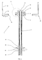
- Fig. 1 illustrates a centre-opening door system 100 commonly used in modern elevator installations.
- the door system 100 comprises a left and a right door 102a,102b respectively which for simplicity have each been shown as consisting of a single panel. It will be readily appreciated that the invention is not limited to such a construction as it can be used equally effectively on multi-panel doors and in telescopic rather than centre-opening door systems.
- the doors 102a,102b are suspended in a conventional manner by hangers 104 from a door track 106.
- the hangers 104 are connected to a transmission belt 108 which is driven by a motor 110 to move the door panels 102a,102b in opposing directions.
- the function of the motor 110 is governed by a door controller 114.
- the track 106, hangers 104, transmission belt 108, motor 110 and controller 114 are generally invisible to passengers as they are all contained within or above a door transom 112 defining the uppermost part of a doorway.
- a retractable safety edge mechanism 1 according to the present invention is provided for each of the doors 102a,102b.
- the retractable safety edge mechanisms 1 are shown in more detail in Fig. 2 , however, so as to avoid unnecessary repetition, the following description refers to the components, construction and function of only one of the retractable safety edge mechanisms 1 (the other being identical).
- the retractable safety edge mechanism 1 includes a safety edge 2 configured to extend substantially the full length of the door 102a,102b and to project ahead of the leading edge of the door 102a,102b.
- the safety edge 2 is supported by means of pivots 14,34 on a pair of links, the upper link being designated 8 and the lower link 28.
- These support links 8,28 are rotatably mounted on fulcrums 16,36 provided on mounting plates 18,38, which in use are secured to the door 102a,102b using any conventional fastening technique.
- a retraction lever 22 is also pivotally mounted on the fulcrum 16 of the upper link 8. As can be clearly seen from the figure, a protruding end 23 of the retraction lever 22 extends above and ahead of the safety edge 2.
- the retractable safety edge mechanism 1 also includes a bracket 40 having a vertical support 42 which in use is secured to the door transom 112 as shown in Fig. 1 , and a horizontal abutment 44.
- the abutment 44 is extensible in the horizontal direction x and includes a bumper 46 secured to an end facing the safety edge 2.
- the bumper 46 can be manufactured from a sound and vibration absorbing material such as rubber.
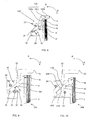
- Figure 3 is an exploded view of section A of Fig. 2 illustrating in greater detail the upper mounting plate 18 and the components of the retractable safety edge mechanism 1 attached thereto.
- the fulcrum 16 is inserted through a hole 19 provided in the mounting plate 18 so that a head of the fulcrum 16 abuts a rear surface of the mounting plate 18.
- the retraction lever 22 and the upper support link 8 are mounted, by way of corresponding holes 25,9 provided therein, on the fulcrum 16.
- the retraction lever 22 and the upper support link 8 are retained on, and prevented from axial movement along, the fulcrum 16 by a circlip 17.
- the upper mounting plate 18 also supports two stoppers 20,21 which limit rotation of the retraction lever 22 and the upper support link 8 about the fulcrum 16 in an extension direction E and a retraction direction R, respectively.
- the retraction lever 22 includes a protruding end 23 positioned above and extending ahead of the safety edge 2, a stopper 24 mounted in close proximity to an end remote to the protruding end 23, and a magnet 26 suspended underneath the retraction lever 22.
- the upper support link 8 includes the pivot 14 on which the safety edge 2 is mounted, a chamfered end 10 remote from the pivot 14 for engagement with a stop 24 mounted on the retraction lever 22, and a magnetically operable contact switch 12 suspended underneath the link 8.
- the safety edge 2 comprises a rigid support channel 6 having a hole 7 into which the pivot 14 on the link 8 is inserted, and a deformable member 4 positioned ahead of the rigid support channel 6 for impacting with an object obstructing the path of the closing door 102a.
- the centre of gravity of the retraction lever 22 lies between its mounting hole 25 and the protruding end 23 (or to the right of the fulcrum 16 as shown in the Fig.). Accordingly, with no external forces acting on the retraction lever 22, gravitational force biases the lever 22 in the extension direction E to its rest position where it abuts against the upper stopper 20 on the mounting plate 18. Similarly, the weight of the safety edge 2 pivotally mounted on the support link 8 biases the link 8 in the extension direction E to its rest position where the chamfered end 10 abuts against the stop 24 on the retraction lever 22. In their respective rest positions, the lever 22 and the link 8 lie alongside each other as do the magnet 26 and the contact switch 12. This alignment of the magnet 26 with the contact switch 12 maintains the switch 12 in an ON state. In use, the contact switch 12 is connected by means of a convention cable (not shown) to the door controller 114.
- Figs. 4 to 7 illustrate all the operating conditions and positions that the retractable safety mechanism 1 undergoes in use.
- Fig. 4 illustrates the retractable safety edge mechanism 1 with the door 102a at its fully opened position.
- the bumper 46 mounted on the horizontal abutment 44 of the bracket 40 engages with the stop 24 mounted on the retraction lever 22 (or alternatively, the bumper 46 can be positioned for direct engagement with the retraction lever 22) causing simultaneous rotation of the lever 22 and the support link 8 in the retraction direction R about the fulcrum 16. Since there is no relative rotation between the lever 22 and the link 8, the magnet 26 and the contact switch 12 remain in alignment during this operation and therefore the switch 12 remains ON. Thereby, the safety edge 2 is retracted without the switch 12 signalling the door controller 114 to halt or reverse the motor 110.
- Fig. 5 illustrates the retractable safety edge mechanism 1 with the door 102a in an intermediate position.
- the contact switch 12 remains ON permitting normal operation of the controller 114.
- Fig. 6 illustrates the retractable safety edge mechanism 1 when the safety edge 2 comes into contact with an obstruction, represented by a force F, during a closing operation of the door 102a.
- the force F acting on the safety edge is translated into rotation of the support link 8 in the retraction direction R about the fulcrum 16.
- the retraction lever 22 remains in its rest position in abutment against the upper stopper 20 mounted on the mounting plate 18.
- This relative rotation between the link 8 and the lever 22 brings the magnet 26 and the contact switch 12 out of alignment with the switch thereby sending an OFF signal to the door controller 114 which immediately halts or reverses the operation of motor 110. Accordingly, the door 102a is stopped or re-opened to prevent further movement against the obstruction.
- Fig. 7 illustrates the retractable safety edge mechanism 1 with the door 102a at its fully closed position.
- the protruding end 23 of the retraction lever 22 comes into contact with the corresponding protruding end of the retraction lever mounted on the opposing door 102b.
- This causes simultaneous rotation of the lever 22 and the link 8 in the retraction direction R. Since there is no relative rotation between the lever 22 and the link 8, the magnet 26 and the contact switch 12 remain in alignment during this operation and therefore the switch 12 remains ON. Thereby, the safety edge 2 is retracted without the switch 12 signalling the door controller 114 to halt or reverse the motor 110.
- Fig. 8 illustrates a partial view of a retractable safety edge mechanism 200 according to a second embodiment of the invention.
- the figure generally corresponds with Fig. 5 in that it shows the retractable safety edge mechanism 200 with the door 102a in an intermediate position.
- the lever mechanism 122 comprises a first lever 122a mounted on the fulcrum 16 and a self-levelling second lever 122b mounted on a frictionless pivot 122c provided on the first lever 122a.
- the first lever 122a and the support link 8 are at their rest positions with the first lever 22 abutting the upper stopper 20 mounted on the mounting plate 18 and the chamfered end 10 of the support link 8 resting against the stop 24 of first lever 22.
- the protruding end 23 of the self-levelling second lever 122b comes into contact with the corresponding protruding end of the retraction lever mounted on the opposing door 102b.
- the second lever 122b remains substantially horizontal during further movement of the door 102a in the closing direction, it transmits horizontal force through the pivot 122c to the first lever 122a causing simultaneous rotation of the first lever 122a and the support link 8 in the retraction direction R.
- the magnet 26 and the contact switch 12 remain in alignment for all operating conditions except for when the safety edge 2 comes into contact with an obstruction during a closing operation of the door 102a.
- the force F representative of the obstruction causes independent rotation of the link 8 in the retraction direction R bringing the magnet 26 and the contact switch 12 out of alignment and causing the door controller 114 to immediately halt or reverse the operation of motor 110.
- Figure 9 is a partial view of a retractable safety edge mechanism 300 according to a third embodiment of the invention.
- the fulcrum 16 of the present embodiment is disposed on the lever 22 at an end remote from the protruding end 23 and on the link 8 at an end remote from the safety edge mounting pivot 14.
- the rest position as shown no external forces act of the retractable safety edge mechanism 300 and thus both the retraction lever 22 and the support link 8 are at their rest positions with the lever 22 abutting the lower stopper 21 mounted on the mounting plate 18 and the support link 8 resting against a bracket 124 extending from the lever 22 underneath the link 8.
- the bracket 124 ensures simultaneous rotation of the lever 22 and the link 8 in the retraction direction R as the door 102a approaches its fully closed position. If the safety edge 2 engages with an obstruction during a closing operation of the door 102a, the link 8 rotates independently of the lever 22 in the retraction direction causing the switch 12 to signal the door controller 114 to immediately halt or reverse the operation of motor 110.
- the retractable safety edge mechanism 300 of the present embodiment cannot be used to retract the safety edge 2 when the door 102a approaches its fully opened position (and therefore the bracket 40 is redundant), the skilled person will appreciate that with minor modification to the lever 22 this function can be accommodated.
- FIG. 10 is a partial view of a retractable safety edge mechanism 400 according to a fourth embodiment of the invention wherein the retraction lever 22 is disposed on a second fulcrum 116 above the support link 8 within the same vertical plane. In the rest position as shown, no external forces act of the retractable safety edge mechanism 400 and thus both the retraction lever 22 and the support link 8 are at their rest positions with the lever 22 abutting the upper stopper 20 mounted on the mounting plate 18 and the support link 8 resting against an abutment 224 mounded on the underside of the lever 22.
- the bumper 46 mounted on the horizontal abutment 44 of the bracket 40 engages with the retraction lever 22 causing simultaneous movement of the lever 22 and the support link 8 in the retraction direction R about their respective fulcrums 116,16.
- the same simultaneous movement is exhibited when the door 102a approaches its fully closed position.
- the link 8 rotates independently of the lever 22 in the retraction direction R. This independent rotation of the link 8 breaks a contact between a switch 212 mounted on the link 8 and a switch operator 226 mounted on the lever 22 causing the switch 12 to signal the door controller 114 to immediately halt or reverse the operation of motor 110.
- the lever mechanism 22;122 is biased by gravity in the extension direction E.
- a resilient member such as a spring.
- a spring can also provided on the link 8 to partially counteract the weight of the safety edge 2.
- the invention has been specifically described for use on a centre-opening door system 100.
- the skilled person will easily acknowledge that the invention is equally applicable to door systems 100 incorporating a single telescopic door.
- the protruding end 23 of the lever mechanism 22;122 would abut the door jamb such that further movement of the door in the closing direction will cause simultaneous rotation of the lever mechanism 22;122 and link 8 to retract the safety edge 2.
Abstract
Description
- The invention relates to the field of automatically operated sliding doors and, in particular, to a retractable safety edge mechanism for mounting on such a door, a method for installing the retractable safety edge mechanism on the door and the resultant door system obtained.
- A conventional retractable safety edge mechanism generally includes a safety edge pivotally supported by links which in turn are rotatably mounted to the door so that the safety edge is parallel to, and projects ahead of, a leading edge of the door. In such an arrangement, if the safety edge encounters any obstruction during a closing operation of the door it retracts and thereby the links are simultaneously rotated. This retraction of the safety edge or rotation of the support links is detected by switch means which immediately signals the halting, and preferably re-opening, of the door.
- It is often necessary to retract the safety edge when the door nears its fully closed position. For example, in the case of two centre-opening doors it is clearly desirable to retract the safety edges so that they will not be deformed by continually bumping against each other as the doors fully close.
JP-02225287-A JP-02225287-A - The linkage arm is connected to and therefore adds weight to the door. Since the maximum kinetic energy of the sliding door is restricted by regulation (see for example European Standard EN 81-1:1998, §8.7.2.1.1.2 which limits the kinetic energy to 10 J), this additional weight from the linkage arm effectively reduces the maximum permissible closing speed of the door. Furthermore, the linkage arm increases both the initial and the maintenance costs of the door.
- Moreover, the function of the linkage arm is essentially distance dependent as it travels with, and spans the entire path of, the door to retract the safety edge as the door approaches its fully closed position. The linkage arm assumes its active state only when the door is at a specific position along its travel path. Hence, a given linkage arm can only be used on doors having the same travel path. Accordingly, doors systems having different travel paths require different linkage arms.
- Another example is described in document
GB-A-1468910 - Accordingly, an objective of the present invention is to overcome the problems associated with the prior art. In particular, the invention seeks to reduce the number of components in a retractable safety edge mechanism without deteriorating its functionality so as to simplify installation and reduce weight, cost and complexity. Furthermore, the invention seeks to provide a retractable safety edge mechanism which can be universally applied to door systems used to close openings of different widths.
- These objectives are achieved by a retractable safety edge mechanism according to the invention, a powered door system incorporating the retractable safety edge mechanism and a method for installing the retractable safety edge mechanism in a powered door system.
- The retractable safety edge mechanism for use on a powered door system comprises a safety edge for projecting ahead of a leading edge of a door, a link attached to the safety edge for pivotal fixation to the door, a lever mechanism for pivotal fixation to the door, and switch means disposed on one or both of the link and the lever mechanism operable by relative movement therebetween wherein rotation of the lever mechanism in a retraction direction causes rotation of the link to retract the extended safety edge CHARACTERIZED IN THAT the lever mechanism projects ahead of the safety edge.
- Accordingly, as the door approaches its closed position, the lever mechanism which extends ahead of the safety edge will abut a door jamb (or alternatively a similar lever mounted on an opposing door of a centre-opening door system) such that further movement of the door in the closing direction will cause the lever mechanism to rotate in the retraction direction thereby effecting simultaneous rotation of the link and retraction of the extended safety edge. Furthermore, if the safety edge engages with an obstruction during a closing operation of the door, the link rotates independently of the lever mechanism in the retraction direction to operate the switch means.
- The retractable safety edge mechanism according to the invention commences retraction of the safety edge when the leading edge of the door reaches a specific distance from its fully closed position. That specific distance is defined by the amount to which the lever mechanism projects ahead of the leading edge. Hence, the retractable safety edge mechanism will operate effectively irrespective of the total travel path of the door, and therefore can be universally applied to door systems having different travel paths.
- Preferably, the link and the lever mechanism are pivotally mounted alongside each other on a common fulcrum. Alternatively, the link can be mounted on a first fulcrum and the lever mechanism can be disposed above the link on a second fulcrum. With such an arrangement, the link and lever mechanism are in the same vertical plane enabling a reduction in the width of the retractable safety edge mechanism.
- Preferably, the retractable safety edge mechanism includes a mounting plate on which the link and lever mechanism are pivotally mounted. Accordingly, the components of the retractable safety edge mechanism can be pre-mounted on the mounting plate at a factory making on site installation easier.
- Preferably, the retractable safety edge mechanism further comprises a bracket for fixation to a stationary part of the door system and for abutment against the lever mechanism as the door approaches its fully opened position. Hence, when the door approaches the fully opened position, the bracket engages the lever mechanism such that further movement of the door in the opening direction will cause the lever mechanism to rotate in the retraction direction thereby effecting simultaneous rotation of the linkage and retraction of the extended safety edge.
- The horizontal length of the bracket depends on the width of the panel(s) used in the door. Clearly, the bracket can be supplied with a specific length for a door having a specific panel width, however, preferably the bracket is horizontally adjustable so that the one bracket can be used for all conceivable door systems.
- Preferably, a portion of the lever mechanism that projects ahead of the safety edge is positioned above the safety edge. Accordingly, the safety edge and the lever can be located in the same plane (saving space) without adversely affecting their respective functionality.
- Preferably, in a powered door system incorporating the retractable safety edge mechanism the portion of the lever mechanism that projects ahead of the safety edge is contained within or above a door transom. Hence, the lever mechanism does not obstruct the opening and is not visible to people passing through the opening.
- The present invention is herein described by way of specific examples with reference to the accompanying drawings in which:
-
Figure 1 is a perspective view of a centre-opening door system having doors incorporating retractable safety edge mechanisms according to a first embodiment of the invention; -
Figure 2 is a plan view of the components of the retractable safety edge mechanisms illustrated inFig. 1 ; -
Figure 3 is an exploded view of section A ofFig. 2 illustrating the main components of the retractable safety edge mechanism in more detail; -
Figure 4 is a partial view of the retractable safety edge mechanism ofFig. 3 with the door in the fully opened position; -
Figure 5 is a partial view of the retractable safety edge mechanism ofFig. 3 as the door moves to an intermediate position along its travel path; -
Figure 6 is similar toFig. 5 except it illustrates the situation when the safety edge encounters an obstruction during the closing operation of the door; -
Figure 7 is a partial view of the retractable safety edge mechanism ofFig. 3 with the door in the fully closed position; -
Figure 8 is a partial view of a retractable safety edge mechanism according to a second embodiment of the invention as the door moves to an intermediate position along its travel path; -
Figure 9 is a partial view of a retractable safety edge mechanism according to a third embodiment of the invention; and -
Figure 10 is a partial view of a retractable safety edge mechanism according to a fourth embodiment of the invention. -
Fig. 1 illustrates a centre-openingdoor system 100 commonly used in modern elevator installations. Thedoor system 100 comprises a left and aright door doors hangers 104 from adoor track 106. Thehangers 104 are connected to atransmission belt 108 which is driven by amotor 110 to move thedoor panels motor 110 is governed by adoor controller 114. Thetrack 106,hangers 104,transmission belt 108,motor 110 andcontroller 114 are generally invisible to passengers as they are all contained within or above adoor transom 112 defining the uppermost part of a doorway. A retractablesafety edge mechanism 1 according to the present invention is provided for each of thedoors - The retractable
safety edge mechanisms 1 are shown in more detail inFig. 2 , however, so as to avoid unnecessary repetition, the following description refers to the components, construction and function of only one of the retractable safety edge mechanisms 1 (the other being identical). The retractablesafety edge mechanism 1 includes asafety edge 2 configured to extend substantially the full length of thedoor door safety edge 2 is supported by means ofpivots lower link 28. These support links 8,28, in turn, are rotatably mounted onfulcrums plates door retraction lever 22 is also pivotally mounted on thefulcrum 16 of theupper link 8. As can be clearly seen from the figure, a protrudingend 23 of theretraction lever 22 extends above and ahead of thesafety edge 2. - The retractable
safety edge mechanism 1 also includes abracket 40 having avertical support 42 which in use is secured to thedoor transom 112 as shown inFig. 1 , and ahorizontal abutment 44. Preferably theabutment 44 is extensible in the horizontal direction x and includes abumper 46 secured to an end facing thesafety edge 2. Thebumper 46 can be manufactured from a sound and vibration absorbing material such as rubber. -
Figure 3 is an exploded view of section A ofFig. 2 illustrating in greater detail the upper mountingplate 18 and the components of the retractablesafety edge mechanism 1 attached thereto. Thefulcrum 16 is inserted through ahole 19 provided in the mountingplate 18 so that a head of thefulcrum 16 abuts a rear surface of the mountingplate 18. - The
retraction lever 22 and theupper support link 8 are mounted, by way of correspondingholes fulcrum 16. Theretraction lever 22 and theupper support link 8 are retained on, and prevented from axial movement along, thefulcrum 16 by acirclip 17. The upper mountingplate 18 also supports twostoppers retraction lever 22 and theupper support link 8 about the fulcrum 16 in an extension direction E and a retraction direction R, respectively. - The
retraction lever 22 includes aprotruding end 23 positioned above and extending ahead of thesafety edge 2, astopper 24 mounted in close proximity to an end remote to theprotruding end 23, and amagnet 26 suspended underneath theretraction lever 22. Theupper support link 8 includes thepivot 14 on which thesafety edge 2 is mounted, achamfered end 10 remote from thepivot 14 for engagement with astop 24 mounted on theretraction lever 22, and a magneticallyoperable contact switch 12 suspended underneath thelink 8. Thesafety edge 2 comprises arigid support channel 6 having ahole 7 into which thepivot 14 on thelink 8 is inserted, and adeformable member 4 positioned ahead of therigid support channel 6 for impacting with an object obstructing the path of theclosing door 102a. - The centre of gravity of the
retraction lever 22 lies between its mountinghole 25 and the protruding end 23 (or to the right of the fulcrum 16 as shown in the Fig.). Accordingly, with no external forces acting on theretraction lever 22, gravitational force biases thelever 22 in the extension direction E to its rest position where it abuts against theupper stopper 20 on the mountingplate 18. Similarly, the weight of thesafety edge 2 pivotally mounted on thesupport link 8 biases thelink 8 in the extension direction E to its rest position where thechamfered end 10 abuts against thestop 24 on theretraction lever 22. In their respective rest positions, thelever 22 and thelink 8 lie alongside each other as do themagnet 26 and thecontact switch 12. This alignment of themagnet 26 with thecontact switch 12 maintains theswitch 12 in an ON state. In use, thecontact switch 12 is connected by means of a convention cable (not shown) to thedoor controller 114. -
Figs. 4 to 7 illustrate all the operating conditions and positions that theretractable safety mechanism 1 undergoes in use.Fig. 4 illustrates the retractablesafety edge mechanism 1 with thedoor 102a at its fully opened position. As thedoor 102a moves to this position, thebumper 46 mounted on thehorizontal abutment 44 of thebracket 40 engages with thestop 24 mounted on the retraction lever 22 (or alternatively, thebumper 46 can be positioned for direct engagement with the retraction lever 22) causing simultaneous rotation of thelever 22 and thesupport link 8 in the retraction direction R about thefulcrum 16. Since there is no relative rotation between thelever 22 and thelink 8, themagnet 26 and thecontact switch 12 remain in alignment during this operation and therefore theswitch 12 remains ON. Thereby, thesafety edge 2 is retracted without theswitch 12 signalling thedoor controller 114 to halt or reverse themotor 110. -
Fig. 5 illustrates the retractablesafety edge mechanism 1 with thedoor 102a in an intermediate position. In this position, no external forces act of the retractablesafety edge mechanism 1 and thus both theretraction lever 22 and thesupport link 8 are at their rest positions with thelever 22 abutting theupper stopper 20 mounted on the mountingplate 18 and thechamfered end 10 of thesupport link 8 resting against thestop 24 of theretraction lever 22. Here again, there is no relative rotation between thelever 22 and thelink 8 and therefore thecontact switch 12 remains ON permitting normal operation of thecontroller 114. -
Fig. 6 illustrates the retractablesafety edge mechanism 1 when thesafety edge 2 comes into contact with an obstruction, represented by a force F, during a closing operation of thedoor 102a. The force F acting on the safety edge is translated into rotation of thesupport link 8 in the retraction direction R about thefulcrum 16. However, theretraction lever 22 remains in its rest position in abutment against theupper stopper 20 mounted on the mountingplate 18. This relative rotation between thelink 8 and thelever 22 brings themagnet 26 and thecontact switch 12 out of alignment with the switch thereby sending an OFF signal to thedoor controller 114 which immediately halts or reverses the operation ofmotor 110. Accordingly, thedoor 102a is stopped or re-opened to prevent further movement against the obstruction. -
Fig. 7 illustrates the retractablesafety edge mechanism 1 with thedoor 102a at its fully closed position. As thedoor 102a approaches this position (as shown inFig. 2 ), the protrudingend 23 of theretraction lever 22 comes into contact with the corresponding protruding end of the retraction lever mounted on the opposingdoor 102b. This causes simultaneous rotation of thelever 22 and thelink 8 in the retraction direction R. Since there is no relative rotation between thelever 22 and thelink 8, themagnet 26 and thecontact switch 12 remain in alignment during this operation and therefore theswitch 12 remains ON. Thereby, thesafety edge 2 is retracted without theswitch 12 signalling thedoor controller 114 to halt or reverse themotor 110. - The skilled person will appreciate that many different variations are possible to achieve the same objective. For example, any lever mechanism can be used in place of the
retraction lever 22 so long as it is capable of translating a horizontal force exerted on the protrudingend 23 into a rotation of thelink 8 about the fulcrum 16 in the retraction direction R to retract thesafety edge 2. Such an example is given inFig. 8 which illustrates a partial view of a retractablesafety edge mechanism 200 according to a second embodiment of the invention. The figure generally corresponds withFig. 5 in that it shows the retractablesafety edge mechanism 200 with thedoor 102a in an intermediate position. However, instead of having asingle lever 22 mounted on thefulcrum 16, thelever mechanism 122 comprises afirst lever 122a mounted on thefulcrum 16 and a self-levellingsecond lever 122b mounted on africtionless pivot 122c provided on thefirst lever 122a. In the position shown, no external forces act of the retractablesafety edge mechanism 200 and thus both thefirst lever 122a and thesupport link 8 are at their rest positions with thefirst lever 22 abutting theupper stopper 20 mounted on the mountingplate 18 and thechamfered end 10 of thesupport link 8 resting against thestop 24 offirst lever 22. As thedoor 102a approaches the fully closed position, the protrudingend 23 of the self-levellingsecond lever 122b comes into contact with the corresponding protruding end of the retraction lever mounted on the opposingdoor 102b. Although thesecond lever 122b remains substantially horizontal during further movement of thedoor 102a in the closing direction, it transmits horizontal force through thepivot 122c to thefirst lever 122a causing simultaneous rotation of thefirst lever 122a and thesupport link 8 in the retraction direction R. As in the previous embodiment, themagnet 26 and thecontact switch 12 remain in alignment for all operating conditions except for when thesafety edge 2 comes into contact with an obstruction during a closing operation of thedoor 102a. Here again, the force F representative of the obstruction causes independent rotation of thelink 8 in the retraction direction R bringing themagnet 26 and thecontact switch 12 out of alignment and causing thedoor controller 114 to immediately halt or reverse the operation ofmotor 110. -
Figure 9 is a partial view of a retractablesafety edge mechanism 300 according to a third embodiment of the invention. Instead of providing the fulcrum 16 at an intermediate along theretraction lever 22 and thesupport link 8, thefulcrum 16 of the present embodiment is disposed on thelever 22 at an end remote from the protrudingend 23 and on thelink 8 at an end remote from the safetyedge mounting pivot 14. In the rest position as shown, no external forces act of the retractablesafety edge mechanism 300 and thus both theretraction lever 22 and thesupport link 8 are at their rest positions with thelever 22 abutting thelower stopper 21 mounted on the mountingplate 18 and thesupport link 8 resting against abracket 124 extending from thelever 22 underneath thelink 8. Thebracket 124 ensures simultaneous rotation of thelever 22 and thelink 8 in the retraction direction R as thedoor 102a approaches its fully closed position. If thesafety edge 2 engages with an obstruction during a closing operation of thedoor 102a, thelink 8 rotates independently of thelever 22 in the retraction direction causing theswitch 12 to signal thedoor controller 114 to immediately halt or reverse the operation ofmotor 110. Although the retractablesafety edge mechanism 300 of the present embodiment cannot be used to retract thesafety edge 2 when thedoor 102a approaches its fully opened position (and therefore thebracket 40 is redundant), the skilled person will appreciate that with minor modification to thelever 22 this function can be accommodated. In particular, if thelever 22 was extended beyond thefulcrum 16 and thelink 8 to provide an abutment surface for thebumper 46 on thebracket 40, then as thedoor 102a approaches its fully opened position, thebumper 46 will engage with thelever 22 causing simultaneous rotation of thelever 22 and thelink 8 in the retraction direction R. - In the previously described embodiments, the
lever mechanism 22;122 is always disposed alongside thelink 8 on thesame fulcrum 16.Figure 10 is a partial view of a retractablesafety edge mechanism 400 according to a fourth embodiment of the invention wherein theretraction lever 22 is disposed on asecond fulcrum 116 above thesupport link 8 within the same vertical plane. In the rest position as shown, no external forces act of the retractablesafety edge mechanism 400 and thus both theretraction lever 22 and thesupport link 8 are at their rest positions with thelever 22 abutting theupper stopper 20 mounted on the mountingplate 18 and thesupport link 8 resting against anabutment 224 mounded on the underside of thelever 22. As thedoor 102a approaches its fully opened position, thebumper 46 mounted on thehorizontal abutment 44 of thebracket 40 engages with theretraction lever 22 causing simultaneous movement of thelever 22 and thesupport link 8 in the retraction direction R about theirrespective fulcrums door 102a approaches its fully closed position. If thesafety edge 2 engages with an obstruction during a closing operation of thedoor 1 02a, thelink 8 rotates independently of thelever 22 in the retraction direction R. This independent rotation of thelink 8 breaks a contact between aswitch 212 mounted on thelink 8 and aswitch operator 226 mounted on thelever 22 causing theswitch 12 to signal thedoor controller 114 to immediately halt or reverse the operation ofmotor 110. - In all of the preferred embodiments described, the
lever mechanism 22;122 is biased by gravity in the extension direction E. However, it is equally feasible to bias thelever mechanism 22;122 using a resilient member such as a spring. Furthermore, as well established by the prior art, a spring can also provided on thelink 8 to partially counteract the weight of thesafety edge 2. - The invention has been specifically described for use on a centre-opening
door system 100. However, the skilled person will easily acknowledge that the invention is equally applicable todoor systems 100 incorporating a single telescopic door. In such a case, as thedoor 102a approaches its fully closed position (where the leading edge lies next to a door jamb), the protrudingend 23 of thelever mechanism 22;122 would abut the door jamb such that further movement of the door in the closing direction will cause simultaneous rotation of thelever mechanism 22;122 andlink 8 to retract thesafety edge 2. - Instead of mounting the
lever mechanism 22;122 for engagement with theupper support link 8, it is technically feasible (although not as practical) to mount thelever mechanism 22;122 on thelower mounting plate 38 for engagement with thelower support link 28.
Claims (10)
- A retractable safety edge mechanism (1;200;300;400) for use on a powered door system (100), comprising:a safety edge (2) for projecting ahead of a leading edge of a door (1 02a);a link (8) attached to the safety edge (2) for pivotal fixation to the door (102a);a lever mechanism (22;122) for pivotal fixation to the door (1 02a); andswitch means (12,26;212,226) disposed on one or both of the link (8) and the lever mechanism (22;122) operable by relative movement therebetweenwherein rotation of the lever mechanism (22;122) in a retraction direction (R) causes rotation of the link (8) to retract the extended safety edge (2)CHARACTERIZED IN THAT the lever mechanism (22;122) projects ahead of the safety edge (2).
- A retractable safety edge mechanism (1;200;300) according to claim 1, wherein the link (8) and the lever mechanism (22;122) are pivotally mounted alongside each other on a common fulcrum (16).
- A retractable safety edge mechanism (400) according to claim 1, wherein the link (8) is pivotally mounted on a first fulcrum (16) and the lever mechanism (22) is disposed above the link (8) on a second fulcrum (116).
- A retractable safety edge mechanism (1 ;200;300;400) according to claim 2 or claim 3, further comprising a mounting plate (18) to which the or each fulcrum (16;116) is affixed.
- A retractable safety edge mechanism (1;200;400) according to any preceding claim, further comprising a bracket (40) for fixation to a stationary part (112) of the door system (100) and for abutment against the lever mechanism (22;122) as the door (1 02a) approaches its fully opened position.
- A retractable safety edge mechanism (1;200;400) according to claim 5, wherein the bracket (40) is horizontally adjustable (x).
- A retractable safety edge mechanism according to any preceding claim wherein a portion (23) of the lever mechanism (22;122) that projects ahead of the safety edge (2) is positioned above the safety edge (2).
- A powered door system (100) comprising:a door (1 02a);a motor (110) to drive the door (102a) between its fully opened and fully closed positions;a controller (114) governing the motor (110); anda retractable safety edge mechanism (1 ;200;300;400) including a safety edge (2) projecting ahead of a leading edge of the door (102a), a link (8) attached to the safety edge (2) and pivotally mounted on the door (102a), a lever mechanism (22;122) pivotally mounted on the door (102a), and switch means (12,26;212,226) connected to the controller (114) and disposed on one or both of the link (8) and the lever mechanism (22;122) operable by relative movement therebetweenwherein rotation of the lever mechanism (22;122) in a retraction direction (R) causes rotation of the link (8) to retract the extended safety edge (2)CHARACTERIZED IN THAT the lever mechanism (22;122) projects ahead of the safety edge (2).
- A powered door system (100) according to claim 8, wherein a portion (23) of the lever mechanism (22;122) that projects ahead of the safety edge (2) is contained within or above a door transom (112).
- A method for installing a retractable safety edge mechanism (1;200;300;400) in a powered door system (100), comprising:pivotally mounting a link (8) on a door (1 02a);mounting a safety edge (2) to the link (8) to project ahead of a leading edge of the door (102a);pivotally mounting a lever mechanism (22;122) on the door (102a);providing switch means (12,26;212,226) on one or both of the link (8) and the lever mechanism (22;122) operable by relative movement therebetween; andconnecting the switch means (12,26;212,226) to a door controller (114)wherein rotation of the lever mechanism (22;122) in a retraction direction (R) causes rotation of the link (8) to retract the extended safety edge (2)CHARACTERIZED IN THAT the lever mechanism (22;122) projects ahead of the safety edge (2).
Applications Claiming Priority (1)
| Application Number | Priority Date | Filing Date | Title |
|---|---|---|---|
| EP05105514 | 2005-06-21 |
Publications (2)
| Publication Number | Publication Date |
|---|---|
| EP1736630A1 EP1736630A1 (en) | 2006-12-27 |
| EP1736630B1 true EP1736630B1 (en) | 2008-05-14 |
Family
ID=35207784
Family Applications (1)
| Application Number | Title | Priority Date | Filing Date |
|---|---|---|---|
| EP20060115316 Not-in-force EP1736630B1 (en) | 2005-06-21 | 2006-06-12 | Retractable safety edge mechanism, installation method and resultant door system |
Country Status (4)
| Country | Link |
|---|---|
| US (1) | US20070029808A1 (en) |
| EP (1) | EP1736630B1 (en) |
| AT (1) | ATE395491T1 (en) |
| DE (1) | DE602006001154D1 (en) |
Families Citing this family (4)
| Publication number | Priority date | Publication date | Assignee | Title |
|---|---|---|---|---|
| FR2937364B1 (en) * | 2008-10-21 | 2012-01-06 | Philippe Vossot | MOTORIZATION FOR SLIDING DOOR OF MODULAR ROOF. |
| EP2743226A1 (en) | 2012-12-17 | 2014-06-18 | Inventio AG | Door for a lift system |
| EP2848854B1 (en) * | 2013-09-13 | 2018-08-15 | Strasser Maschinenbau GmbH | Device for locking a movable component |
| WO2020044401A1 (en) * | 2018-08-27 | 2020-03-05 | 三菱電機株式会社 | Elevator door safety apparatus |
Family Cites Families (14)
| Publication number | Priority date | Publication date | Assignee | Title |
|---|---|---|---|---|
| US3040839A (en) * | 1962-06-26 | Mechanism for advancing and retracting safe | ||
| US2687455A (en) * | 1951-03-13 | 1954-08-24 | Horace M Norman | Safety edge mechanism |
| US2687172A (en) * | 1953-07-27 | 1954-08-24 | Horace M Norman | Retracting means for safety edges of elevator doors |
| US3050155A (en) * | 1953-12-21 | 1962-08-21 | Otis Elevator Co | Protective mechanism for doors |
| US2878898A (en) * | 1953-12-21 | 1959-03-24 | Westinghouse Electric Corp | Elevator closure systems |
| US2985258A (en) * | 1957-12-17 | 1961-05-23 | Westinghouse Electric Corp | Closure control mechanism |
| US3063517A (en) * | 1960-03-21 | 1962-11-13 | Toledo Scale Corp | Door safety control |
| US3168165A (en) * | 1962-06-11 | 1965-02-02 | Serge Elevator Company Inc | Protective door reversing means |
| US3315766A (en) * | 1965-11-12 | 1967-04-25 | Otis Elevator Co | Retractable safety edge for doors |
| GB1468910A (en) * | 1975-05-21 | 1977-03-30 | Express Lift Co Ltd | Control arrangements for power operated sliding doors |
| US4693340A (en) * | 1985-09-30 | 1987-09-15 | Shanks Ernest R | Bumper guide assembly for elevator doors |
| JP2620134B2 (en) * | 1989-02-27 | 1997-06-11 | 三菱電機株式会社 | Door safety device for elevator |
| JPH07267548A (en) * | 1994-03-25 | 1995-10-17 | Mitsubishi Denki Bill Techno Service Kk | Door safety device of elevator |
| JP4544673B2 (en) * | 1999-12-06 | 2010-09-15 | オーチス エレベータ カンパニー | Elevator door safety device |
-
2006
- 2006-06-09 US US11/450,614 patent/US20070029808A1/en not_active Abandoned
- 2006-06-12 AT AT06115316T patent/ATE395491T1/en not_active IP Right Cessation
- 2006-06-12 DE DE200660001154 patent/DE602006001154D1/en not_active Expired - Fee Related
- 2006-06-12 EP EP20060115316 patent/EP1736630B1/en not_active Not-in-force
Also Published As
| Publication number | Publication date |
|---|---|
| ATE395491T1 (en) | 2008-05-15 |
| DE602006001154D1 (en) | 2008-06-26 |
| US20070029808A1 (en) | 2007-02-08 |
| EP1736630A1 (en) | 2006-12-27 |
Similar Documents
| Publication | Publication Date | Title |
|---|---|---|
| US7350623B2 (en) | Elevator door apparatus | |
| US5857756A (en) | Lifting and lowering device for furniture elements | |
| US20070261309A1 (en) | Automatic door assembly with telescoping door arm | |
| US7114753B2 (en) | Latch assembly for a sectional door | |
| US6220396B1 (en) | Door restrictor apparatus for elevators | |
| RU2107017C1 (en) | Device for connecting lift well door with lift cabin door for simultaneous movement (design versions) | |
| EP1736630B1 (en) | Retractable safety edge mechanism, installation method and resultant door system | |
| US20090301821A1 (en) | Elevator entrance apparatus | |
| CA2464637A1 (en) | Impactable door | |
| EP3418243B1 (en) | Elevator apparatus | |
| US6145570A (en) | Locking system for sectional doors | |
| CN101023236B (en) | Floor lock | |
| US11603695B2 (en) | Method for mounting a door drive and door drive | |
| JP5449047B2 (en) | Elevator door device with central hinged door | |
| JP2016216036A (en) | Engine hood hinge, engine hood hinge control system, and vehicle | |
| FI128887B (en) | Automatic sliding sash arrangement | |
| CA2384635A1 (en) | Central lock mechanism | |
| KR101849668B1 (en) | Double protective device of parking door | |
| KR101900597B1 (en) | Moving Brackets For door closure installation | |
| JP6956885B2 (en) | Elevator door safety device | |
| CN213265296U (en) | Elevator safety touch panel | |
| JP3356607B2 (en) | Elevator doorway device | |
| US20240044196A1 (en) | Furniture drive system for a movable furniture part | |
| EP0681637B1 (en) | Turning device for overhead sectional doors | |
| JP5140269B2 (en) | Elevator door pull-in detection device and its assembly method |
Legal Events
| Date | Code | Title | Description |
|---|---|---|---|
| PUAI | Public reference made under article 153(3) epc to a published international application that has entered the european phase |
Free format text: ORIGINAL CODE: 0009012 |
|
| AK | Designated contracting states |
Kind code of ref document: A1 Designated state(s): AT BE BG CH CY CZ DE DK EE ES FI FR GB GR HU IE IS IT LI LT LU LV MC NL PL PT RO SE SI SK TR |
|
| AX | Request for extension of the european patent |
Extension state: AL BA HR MK YU |
|
| 17P | Request for examination filed |
Effective date: 20070620 |
|
| AKX | Designation fees paid |
Designated state(s): AT CH DE FR GB LI |
|
| GRAP | Despatch of communication of intention to grant a patent |
Free format text: ORIGINAL CODE: EPIDOSNIGR1 |
|
| GRAS | Grant fee paid |
Free format text: ORIGINAL CODE: EPIDOSNIGR3 |
|
| GRAA | (expected) grant |
Free format text: ORIGINAL CODE: 0009210 |
|
| AK | Designated contracting states |
Kind code of ref document: B1 Designated state(s): AT CH DE FR GB LI |
|
| REG | Reference to a national code |
Ref country code: GB Ref legal event code: FG4D |
|
| REG | Reference to a national code |
Ref country code: CH Ref legal event code: EP |
|
| REF | Corresponds to: |
Ref document number: 602006001154 Country of ref document: DE Date of ref document: 20080626 Kind code of ref document: P |
|
| PGFP | Annual fee paid to national office [announced via postgrant information from national office to epo] |
Ref country code: AT Payment date: 20080616 Year of fee payment: 3 |
|
| PGFP | Annual fee paid to national office [announced via postgrant information from national office to epo] |
Ref country code: DE Payment date: 20080620 Year of fee payment: 3 |
|
| PGFP | Annual fee paid to national office [announced via postgrant information from national office to epo] |
Ref country code: FR Payment date: 20080613 Year of fee payment: 3 |
|
| PLBE | No opposition filed within time limit |
Free format text: ORIGINAL CODE: 0009261 |
|
| STAA | Information on the status of an ep patent application or granted ep patent |
Free format text: STATUS: NO OPPOSITION FILED WITHIN TIME LIMIT |
|
| 26N | No opposition filed |
Effective date: 20090217 |
|
| REG | Reference to a national code |
Ref country code: FR Ref legal event code: ST Effective date: 20100226 |
|
| PG25 | Lapsed in a contracting state [announced via postgrant information from national office to epo] |
Ref country code: FR Free format text: LAPSE BECAUSE OF NON-PAYMENT OF DUE FEES Effective date: 20090630 |
|
| PG25 | Lapsed in a contracting state [announced via postgrant information from national office to epo] |
Ref country code: AT Free format text: LAPSE BECAUSE OF NON-PAYMENT OF DUE FEES Effective date: 20090612 Ref country code: DE Free format text: LAPSE BECAUSE OF NON-PAYMENT OF DUE FEES Effective date: 20100101 |
|
| REG | Reference to a national code |
Ref country code: CH Ref legal event code: PL |
|
| GBPC | Gb: european patent ceased through non-payment of renewal fee |
Effective date: 20100612 |
|
| PG25 | Lapsed in a contracting state [announced via postgrant information from national office to epo] |
Ref country code: LI Free format text: LAPSE BECAUSE OF NON-PAYMENT OF DUE FEES Effective date: 20080630 Ref country code: CH Free format text: LAPSE BECAUSE OF NON-PAYMENT OF DUE FEES Effective date: 20080630 |
|
| PG25 | Lapsed in a contracting state [announced via postgrant information from national office to epo] |
Ref country code: CH Free format text: LAPSE BECAUSE OF NON-PAYMENT OF DUE FEES Effective date: 20100630 Ref country code: LI Free format text: LAPSE BECAUSE OF NON-PAYMENT OF DUE FEES Effective date: 20100630 |
|
| PG25 | Lapsed in a contracting state [announced via postgrant information from national office to epo] |
Ref country code: GB Free format text: LAPSE BECAUSE OF NON-PAYMENT OF DUE FEES Effective date: 20100612 |