WO2020040156A1 - 作業機操作具及び作業機操作システム - Google Patents
作業機操作具及び作業機操作システム Download PDFInfo
- Publication number
- WO2020040156A1 WO2020040156A1 PCT/JP2019/032500 JP2019032500W WO2020040156A1 WO 2020040156 A1 WO2020040156 A1 WO 2020040156A1 JP 2019032500 W JP2019032500 W JP 2019032500W WO 2020040156 A1 WO2020040156 A1 WO 2020040156A1
- Authority
- WO
- WIPO (PCT)
- Prior art keywords
- signal
- unit
- transmission unit
- front loader
- work implement
- Prior art date
- Legal status (The legal status is an assumption and is not a legal conclusion. Google has not performed a legal analysis and makes no representation as to the accuracy of the status listed.)
- Ceased
Links
Images





Classifications
-
- B—PERFORMING OPERATIONS; TRANSPORTING
- B62—LAND VEHICLES FOR TRAVELLING OTHERWISE THAN ON RAILS
- B62D—MOTOR VEHICLES; TRAILERS
- B62D49/00—Tractors
-
- E—FIXED CONSTRUCTIONS
- E02—HYDRAULIC ENGINEERING; FOUNDATIONS; SOIL SHIFTING
- E02F—DREDGING; SOIL-SHIFTING
- E02F9/00—Component parts of dredgers or soil-shifting machines, not restricted to one of the kinds covered by groups E02F3/00 - E02F7/00
- E02F9/20—Drives; Control devices
-
- G—PHYSICS
- G05—CONTROLLING; REGULATING
- G05G—CONTROL DEVICES OR SYSTEMS INSOFAR AS CHARACTERISED BY MECHANICAL FEATURES ONLY
- G05G9/00—Manually-actuated control mechanisms provided with one single controlling member co-operating with two or more controlled members, e.g. selectively, simultaneously
- G05G9/02—Manually-actuated control mechanisms provided with one single controlling member co-operating with two or more controlled members, e.g. selectively, simultaneously the controlling member being movable in different independent ways, movement in each individual way actuating one controlled member only
- G05G9/04—Manually-actuated control mechanisms provided with one single controlling member co-operating with two or more controlled members, e.g. selectively, simultaneously the controlling member being movable in different independent ways, movement in each individual way actuating one controlled member only in which movement in two or more ways can occur simultaneously
- G05G9/047—Manually-actuated control mechanisms provided with one single controlling member co-operating with two or more controlled members, e.g. selectively, simultaneously the controlling member being movable in different independent ways, movement in each individual way actuating one controlled member only in which movement in two or more ways can occur simultaneously the controlling member being movable by hand about orthogonal axes, e.g. joysticks
Definitions
- the present invention relates to a technology of a work implement operating tool and a work implement operation system for operating a work implement attached to a work vehicle.
- Patent Document 1 the technology of a work implement operating tool and a work implement operation system for operating a work implement attached to a work vehicle is known. For example, as described in Patent Document 1.
- the work implement operating tool (control lever) described in Patent Document 1 is for operating a front loader (work implement), and is configured to be operable (swinging) in the front-rear direction and the left-right direction.
- the work implement operating tool can raise and lower the boom of the front loader by being operated in the front-rear direction, and can swing the bucket of the front loader by being operated in the left-right direction.
- Patent Literature 1 the work implement operating tool described in Patent Literature 1 can operate only the front loader. For this reason, in Patent Literature 1, the use of the work implement operating tool is limited, and it may be difficult to improve convenience.
- the present invention has been made in view of the above situation, and a problem to be solved is to provide a work implement operating tool and a work implement operating system capable of improving convenience.
- the working machine operating tool of the present invention is configured to be capable of inputting a predetermined direction, a lever capable of operating a working machine including at least a front loader in accordance with the input direction, and a first operating unit provided on the lever And
- the lever can operate at least a front loader, and the first operating section can operate at least another working implement different from the front loader.
- the working implement operating tool further includes a switching unit that can switch between a state in which the front loader can be operated and a state in which the other work equipment can be operated.
- the working implement operating tool of the present invention further includes a second operating section capable of operating the front loader and the other working implement according to an operation amount.
- the working machine operating system of the present invention includes the working machine operating tool, a signal transmitting unit that transmits a signal corresponding to an operation of the working machine operating tool, the signal transmitting unit, the front loader, and / or the other. And a management unit that manages communication with the work machine.
- the management unit converts a signal received from the signal transmission unit into a signal corresponding to the front loader and / or the another work machine and transmits the signal. It is provided.
- the management unit can change a signal received from the signal transmission unit and a signal converted by the translation unit into an arbitrary correspondence.
- the management unit changes the setting of the signal transmitting unit to operate the working machine operating tool and a signal transmitted from the signal transmitting unit in response to the operation.
- a setting change unit for changing the correspondence relationship with the setting.
- the management unit may arbitrarily associate an operation of the work implement operation implement set by the setting change unit with a signal transmitted from the signal transmission unit in response to the operation. Relationships can be changed.
- the management unit includes a pattern transmission unit that transmits a signal determined according to the predetermined pattern when receiving a signal of a predetermined pattern from the signal transmission unit. Is what you do.
- the pattern transmission unit when the pattern transmission unit receives a signal of a predetermined combination including a plurality of signals from the signal transmission unit, the pattern loader and / or the front loader determined according to the combination.
- a command transmitting unit for transmitting a signal corresponding to a predetermined operation of the other working machine is provided.
- the pattern transmitting unit when the same signal is continuously received for a predetermined time from the signal transmitting unit, the pattern transmitting unit transmits a signal corresponding to the signal even when the signal is not received. It has a continuation transmitting unit for continuing transmission.
- the work implement operating tool includes a lever capable of inputting a predetermined direction, and a switch provided on the lever and capable of operating another work implement different from the front loader.
- the work machine operation system of the present invention the work machine operation tool, a signal transmission unit that transmits a signal according to the operation of the work machine operation tool, and received a signal of a predetermined pattern from the signal transmission unit And a pattern transmitting unit that transmits a signal determined according to the predetermined pattern to the work implement.
- the working machine operating system of the present invention further includes a translating unit that converts a signal received from the signal transmitting unit into a signal corresponding to the working machine and transmits the signal.
- the work machine operation system wherein the translation unit is mounted, a first operation terminal capable of changing a signal received from the signal transmission unit and a signal converted by the translation unit into an arbitrary correspondence. Is further provided.
- the working machine operating system of the present invention changes the setting of the signal transmitting unit to change the correspondence between the operation of the working machine operating tool and the signal transmitted from the signal transmitting unit in response to the operation. It further includes a setting change unit for changing.
- the working machine operation system of the present invention is provided with the setting change unit, and performs the operation of the work machine operation tool set by the setting change unit and a signal transmitted from the signal transmission unit in response to the operation.
- the apparatus further includes a second operation terminal that can be changed to an arbitrary correspondence.
- the working machine operating tool further includes a second operating unit capable of operating the working machine according to an operation amount.
- the pattern transmitting unit when the pattern transmitting unit receives a signal of a predetermined combination including a plurality of signals from the signal transmitting unit, the pattern transmitting unit determines a predetermined state of the working machine determined according to the combination. Is provided with a command transmitting unit for transmitting a signal corresponding to the operation of (1).
- the present invention has the following effects.
- the front loader and other working implements can be operated as required.
- the communication between the work machine operation tool and the front loader and / or another work machine can be managed using the management unit.
- the front loader and the other working machine can be operated.
- a signal corresponding to the front loader and / or another working machine can be transmitted from the signal transmitting unit.
- the working machine even when the signal transmitted from the signal transmitting unit does not correspond to the working machine, the working machine can be operated.
- a signal corresponding to the working machine can be transmitted from the signal transmitting unit.
- FIG. 2 is a side view showing the overall configuration of the tractor.
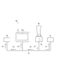
- FIG. 2 is a block diagram showing a work machine operation system.
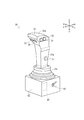
- FIG. 2 is a perspective view showing a work implement operating tool.
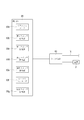
- FIG. 3 is a block diagram illustrating a detection unit and a signal transmission unit.
- FIG. 3 is a conceptual diagram showing various functions of the communication terminal.
- FIG. 4 is a block diagram showing a state where a signal corresponding to a front loader is transmitted from a signal transmission unit.
- FIG. 4 is a block diagram showing a state where a signal corresponding to a rotary tillage device is transmitted from a signal transmission unit.
- FIG. 4 is a block diagram showing a state where a signal corresponding to the front loader replaced by the translation unit is transmitted.
- FIG 4 is a block diagram showing a state where a signal corresponding to the replaced front loader is transmitted from the signal transmission unit.
- the tractor 1 mainly includes a body frame 2, front wheels 3, rear wheels 4, an engine 5, a hood 6, a transmission 7, a hydraulic elevating device 8, a cabin 9, a steering wheel 10, a seat 11, a rotary tilling device 20, and a front loader 30.
- a body frame 2 front wheels 3, rear wheels 4, an engine 5, a hood 6, a transmission 7, a hydraulic elevating device 8, a cabin 9, a steering wheel 10, a seat 11, a rotary tilling device 20, and a front loader 30.
- the body frame 2 is arranged with its longitudinal direction facing the front-back direction.
- the front part of the body frame 2 is supported by a pair of left and right front wheels 3 via a front axle mechanism (not shown).
- a transmission 7 housed in a transmission case is provided at the rear of the body frame 2.
- the rear portion of the transmission 7 is supported by a pair of left and right rear wheels 4 via a rear axle mechanism (not shown).
- An engine 5 is provided at the front of the body frame 2.
- the engine 5 is covered by a hood 6. After the power of the engine 5 is shifted by the transmission 7, the power can be transmitted to the front wheels 3 via the front axle mechanism and can be transmitted to the rear wheels 4 via the rear axle mechanism.
- the front wheel 3 and the rear wheel 4 are driven to rotate by the power of the engine 5, and the tractor 1 can run.
- the power of the engine 5 can be transmitted to the PTO shaft after being shifted by the transmission 7.
- the rotary tilling device 20 is connected to the PTO shaft.
- the rotary tilling device 20 is disposed at the rear of the tractor 1 and mainly includes a transmission case 21, a rotary shaft 22, a plurality of claws 23, and a microcomputer 24 (see FIG. 2).
- the transmission case 21 rotates the rotary shaft 22 by transmitting power from the PTO shaft to the rotary shaft 22.
- the rotary tillage device 20 can plow a field or the like by rotating the plurality of claws 23.
- the rotary tillage device 20 is configured to be able to move up and down by the hydraulic elevating device 8.
- the microcomputer 24 controls the operation of the rotary tillage device 20.
- the microcomputer 24 will be described later.
- the front loader 30 is mounted on the front of tractor 1.
- the front loader 30 mainly includes a support frame 31, a boom 32, a bucket 33, and a microcomputer 34 (see FIG. 2).
- the support frame 31 is fixed to the body frame 2.
- the boom 32 is rotatably connected to the support frame 31 and is disposed so as to extend forward.
- the bucket 33 is rotatably connected to the front end of the boom 32.
- the boom 32 can be rotated with respect to the support frame 31 by expanding and contracting the boom cylinder 32a.
- the bucket 33 can be rotated with respect to the boom 32 by expanding and contracting a bucket cylinder 33a.
- the front loader 30 can carry out the work of transporting earth and sand while rotating the boom 32 and the bucket 33 as appropriate.
- the microcomputer 34 controls the operation of the front loader 30.
- the microcomputer 34 will be described later.
- a cabin 9 is provided midway in the front and rear of the tractor 1 (behind the engine 5). Inside the cabin 9, there is formed a living space 9a on which the worker boards. In the living space 9a, a steering wheel 10 for adjusting a turning angle of the front wheel 3, a seat 11 for an operator to sit, and the like are arranged.
- a work implement operating tool 50 for operating the rotary tillage device 20 and the front loader 30 and a communication terminal 70 that can appropriately communicate with equipment provided in the tractor 1 are arranged.
- the work implement operating tool 50 is provided on the right side of the seat 11.
- the communication terminal 70 is arranged above the meter panel separately from a meter panel (not shown) arranged in front of the seat 11.
- the work machine operation system 40 shown in FIG. 2 includes a work machine operation tool 50 and a communication terminal 70.
- the work implement operating tool 50 shown in FIGS. 2 and 3 is for operation by an operator.
- the work implement operating tool 50 includes a lever 51, a box 52, a first switch 53, a second switch 54, a third switch 55, a fourth switch 56, a dial 57, a changeover switch 58, a detection unit 59 (see FIG. 4), and a signal.
- the transmission unit 60 is provided.
- the lever 51 is used to input a predetermined direction by a tilt operation.
- the lever 51 according to the present embodiment is configured to be able to input a front-rear direction, a left-right direction, and an oblique direction (left front direction, left rear direction, right front direction, and right rear direction).
- the lever 51 includes a main body 51a, a grip 51b, and a boot 51c.
- the main body 51a is formed in a substantially rectangular parallelepiped shape extending in the vertical direction.
- the main body 51a is provided to be swingable in the front-rear direction, the left-right direction, and the oblique direction by being supported by a predetermined support mechanism.
- the main body 51a is configured to return to its original position (a position not swinging in any direction) by being urged by a spring or the like.
- the grip 51b is a portion that is gripped by an operator and is an upper portion of the main body 51a.
- the grip 51b is formed so as to be longer in the front-rear direction width than other portions of the main body 51a, and is formed in a curved shape whose upper surface swells upward.
- the boot 51c covers the lower part of the main body 51a.
- the boot 51c is made of an elastic material such as rubber.
- the box 52 is a substantially box-shaped member.
- the box 52 accommodates the support mechanism for supporting the main body 51a, a signal transmission unit 60 described later, and the like.
- the first switch 53 to the fourth switch 56 are push-button switches for performing a pressing operation.
- the first switch 53 to the fourth switch 56 are provided on the lever 51. More specifically, the first switch 53 and the second switch 54 are provided on the left side of the grip 51b so as to be arranged in front and rear.
- the third switch 55 and the fourth switch 56 are provided on the front side of the grip 51b so as to be aligned left and right.
- the dial 57 is an operating tool for rotating operation.
- the dial 57 is configured to be able to rotate itself (in an analog manner) in a stepless manner.
- the dial 57 is provided on the lever 51 (below the first switch 53 and the second switch 54).
- the changeover switch 58 is operable to operate the front loader 30 using the work implement operating tool 50 and to operate the rotary tillage device 20 (work implements other than the front loader 30) using the work implement operating tool 50.
- the second state is switched.
- the changeover switch 58 is provided on the left side of the box 52.
- the changeover switch 58 according to the present embodiment is configured by a toggle switch that can switch between a state in which the switch is tilted upward and a state in which the switch is tilted downward.
- the switch 58 according to the present embodiment can be switched to the first state when it is tilted upward (when the state shown in FIG. 3 is reached). When the switch 58 is tilted downward, the switch 58 can be switched to the second state.
- the detecting section 59 shown in FIG. 4 is for detecting that the lever 51 or the like has been operated.
- the detection section 59 includes a potentiometer 59a, a first switch detection section 59b, a second switch detection section 59c, a third switch detection section 59d, a fourth switch detection section 59e, a rotary encoder 59f, and a changeover switch detection section 59g.
- a plurality of potentiometers 59a are provided in accordance with the input direction of the lever 51, and detect a swing operation of the lever 51.
- the first switch detector 59b to the fourth switch detector 59e detect a pressing operation of the first switch 53 to the fourth switch 56.
- the rotary encoder 59f detects the amount of turning operation of the dial 57.
- the changeover switch detection unit 59g detects a changeover operation of the changeover switch 58.
- the signal transmitting unit 60 is for transmitting a signal corresponding to the operation of the lever 51 or the like, that is, a signal capable of identifying how the lever 51 or the like is operated.
- the signal transmitting unit 60 transmits a signal of a message ID associated with an operation of the lever 51 or the like.
- the signal transmitting unit 60 is configured by a microcomputer or the like.
- the signal transmission unit 60 is connected to the detection unit 59 and is configured to be able to receive a signal related to a detection result from the detection unit 59. Thereby, the signal transmission unit 60 is configured to be able to acquire the detection result of the detection unit 59 (the detection result of the potentiometer 59a and the like).
- the signal transmission unit 60 is connected to a predetermined power supply P and operates by supplying power from the power supply P.
- the signal transmission unit 60 is connected to an in-vehicle network N such as a CAN (Controller Area Network).
- a communication terminal 70, a microcomputer 24 of the rotary tilling device 20, and a microcomputer 34 of the front loader 30, which will be described later, are connected to the in-vehicle network N according to the present embodiment, in addition to the signal transmission unit 60.
- the signal transmission unit 60 can transmit a signal corresponding to the operation via the in-vehicle network N.
- the microcomputer 24 of the rotary tilling device 20 stores the message ID of the predetermined signal and the operation of the rotary tilling device 20 in association with each other. Further, the microcomputer 34 of the front loader 30 stores a message ID of a predetermined signal and an operation of the front loader 30 in association with each other. As a result, the microcomputers 24 and 34 can execute the determined operation according to the message ID of the received signal. Specifically, for example, when the microcomputer 24 of the rotary tilling apparatus 20 stores the message ID of “1” in association with the operation of rotating the plurality of claws 23, the microcomputer 24 outputs the signal of the message ID of “1”. Upon receipt, the plurality of claws 23 can be rotated according to the message ID.
- the communication terminal 70 shown in FIGS. 2 and 5 manages communication between the signal transmission unit 60, the rotary tilling device 20, and the microcomputers 24 and 34 of the front loader 30.
- the communication terminal 70 mainly includes an arithmetic processing device such as a CPU, a storage device such as a RAM and a ROM, and an input / output device such as a touch panel 70a (see FIG. 2).
- the communication terminal 70 stores applications and various information in the storage device, and can perform various processes by reading and processing the applications and various information with the arithmetic processing device.
- the communication terminal 70 includes a translation unit 71, a setting change unit 72, and a pattern transmission unit 73.
- the translation unit 71 is an application installed on the communication terminal 70.
- the translation unit 71 operates the rotary plow 20 and the front loader 30 by appropriately converting the signal received from the signal transmission unit 60.
- the processing of the translation unit 71 will be described later.
- the setting change unit 72 is an application installed on the communication terminal 70.
- the setting change unit 72 changes the message ID of the signal transmitted from the signal transmission unit 60.
- the processing of the setting change unit 72 will be described later.
- the pattern transmission unit 73 operates the rotary tillage device 20 and the front loader 30 according to a predetermined pattern operation. The processing of the pattern transmission section 73 will be described later.
- the work implement operating tool 50 shown in FIG. 3 can switch between the first state and the second state by appropriately switching the changeover switch 58.
- the changeover switch detection unit 59g illustrated in FIG. 4 detects the operation and transmits the detection result to the signal transmission unit 60. Thereby, the signal transmission unit 60 switches the work implement operating tool 50 to the first state.
- the signal transmission unit 60 transmits the message ID of the signal transmitted in response to the operation of the lever 51, the first switch 53, or the like so as to correspond to the front loader 30, that is, the microcomputer 34 of the front loader 30 Switching is performed so that the message ID can be identified. Thereby, the signal transmission unit 60 switches the signal transmitted by itself to the signal S1 corresponding to the front loader 30.
- the signal transmission unit 60 transmits the signal S1 in accordance with the operation to the device connected to the in-vehicle network N. Broadcast to. That is, the signal transmission unit 60 transmits the signal S1 to the microcomputer 34 of the front loader 30, the microcomputer 24 of the rotary tilling device 20, and the communication terminal 70.
- the microcomputer 34 of the front loader 30 operates the front loader 30 (for example, rotates the boom 32) according to the message ID of the signal S1.
- the work implement operating tool 50 can operate the front loader 30 according to the operation of the lever 51, the first switch 53, and the like.
- the microcomputer 24 and the communication terminal 70 of the rotary tilling apparatus 20 do not operate even if the signal S1 is received.
- the work implement operating tool 50 can operate only the front loader 30 in the first state.
- the signal transmission unit 60 switches the work implement operating tool 50 to the second state.
- the signal transmission unit 60 switches a signal transmitted according to an operation of the lever 51, the first switch 53, or the like, to the signal S2 corresponding to the rotary tilling device 20.
- the signal transmitting unit 60 transmits the signal S2 according to the operation.
- the microcomputer 24 of the rotary tillage device 20 operates the rotary tillage device 20 according to the message ID of the signal S2 (for example, rotates the plurality of claws 23). Thereby, the work implement operating tool 50 can operate the rotary tillage device 20 according to the operation of the lever 51, the first switch 53, and the like.
- the signal transmission unit 60 transmits a signal S2 corresponding to the amount of rotation of the dial 57.
- the operation amount of the rotary tillage device 20 can be adjusted.
- the depth of tilling by the rotary tilling device 20 can be adjusted.
- the operation of the rotary tillage device 20 can be finely controlled, and the operability of the work implement operating tool 50 can be improved.
- the microcomputer 34 and the communication terminal 70 of the front loader 30 operate even when receiving the signal S2. I will not do it.
- the work implement operating tool 50 can operate only the rotary tillage device 20 in the second state.
- the signals S1 and S2 transmitted from the signal transmission unit 60 in response to the operation of the lever 51, the first switch 53, and the like are transmitted to either the front loader 30 or the rotary plow 20. Can be switched to the signals S1 and S2 corresponding to. Thereby, the rotary tillage device 20 and the front loader 30 can be operated as needed.
- the translation unit 71 appropriately converts the signal received from the signal transmission unit 60.
- the front loader 30 when the front loader 30 connected to the tractor 1 is replaced with another model (another front loader 30), the front loader 30 does not correspond to the signal transmitted from the signal transmission unit 60.
- the front loader 30 There are cases. More specifically, there is a case where there is no correspondence between the message ID stored in the microcomputer 34 of the front loader 30 replaced with another model and the message ID of the signal transmitted from the signal transmission unit 60. is there. In this case, even if a signal is transmitted from the signal transmission unit 60, the front loader 30 cannot be operated.
- the translating unit 71 can avoid such a situation by appropriately converting the signal received from the signal transmitting unit 60.
- the translating unit 71 first determines the model of the front loader 30 connected to the tractor 1 by a predetermined means. Thereby, the translating unit 71 can determine the correspondence between the message ID of the signal stored in association with the microcomputer 34 and the operation of the front loader 30 according to the determined model.
- the predetermined means for example, means for determining the model of the front loader 30 by a signal from the microcomputer 34 transmitted when the front loader 30 is replaced with another model, There are means for manually setting the model of the loader 30.
- the translator 71 receives the signal S1 from the signal transmitter 60 (see FIG. 6), the operator instructs based on the signal S1 (see FIG. 6).
- the operation of the front loader 30 (corresponding to the operation) is determined.
- the translating unit 71 determines a message ID that can execute the operation instructed by the operator with the front loader 30 based on the determined model of the front loader 30. After that, the translation unit 71 transmits a signal of the determined message ID, that is, a signal S3 corresponding to the replaced front loader 30.
- the microcomputer 34 of the front loader 30 operates the front loader 30 (for example, rotates the boom 32) according to the message ID of the signal S3.
- the translating unit 71 even if the signal S1 transmitted from the signal transmitting unit 60 does not correspond to the front loader 30, the signal S1 transmitted from the signal transmitting unit 60 and the front loader 30 are separated.
- the work implement operating tool 50 can be operated as if it were corresponding (simulated).
- the front loader 30 that does not correspond to the signal S1 transmitted from the signal transmission unit 60 can be operated by the work implement operating tool 50.
- the translation unit 71 Since the signal S3 transmitted from the translation unit 71 is a signal corresponding to the replaced front loader 30, the microcomputer 24 of the rotary tilling apparatus 20 does not operate even if the signal S3 is received. Thus, the translation unit 71 can operate only the front loader 30 by the signal S3.
- the translation unit 71 performs the same processing as when the front loader 30 is replaced with another model, even when the rotary cultivator 20 is replaced with another model (another rotary cultivator 20). That is, the translation unit 71 determines the model of the rotary tillage device 20 and the operation instructed by the operator, determines the message ID that can execute the operation instructed by the operator based on the model, and replaces the rotary tillage. A signal corresponding to the device 20 is transmitted.
- the signal from the signal transmission unit 60 can be appropriately converted, and a signal suitable for the model of the rotary tilling device 20 and the front loader 30 can be transmitted.
- various work machines a plurality of work machines and work machines of different models
- the use of the work implement operating tool 50 can be expanded and the convenience can be improved.
- a signal suitable for the model of the rotary plow 20 and the front loader 30 can be transmitted, so that the rotary plow 20 and the front loader 30 can be easily operated.
- the setting change unit 72 changes the message ID of the signal transmitted from the signal transmission unit 60.
- the front loader 30 when the front loader 30 is replaced with another model, the front loader 30 may not correspond to the signal transmitted from the signal transmission unit 60 in some cases.
- the setting change unit 72 changes the message ID of the signal transmitted from the signal transmission unit 60 so that the signal transmitted from the signal transmission unit 60 corresponds to the front loader 30, and thus the front end is changed.
- the loader 30 can be operated.
- the setting change unit 72 first determines the model of the front loader 30 connected to the tractor 1 by a predetermined means. Then, the setting change unit 72 rewrites the information on the message ID stored in the signal transmitting unit 60 so that the signal of the message ID corresponding to the model of the front loader 30 is transmitted from the signal transmitting unit 60. Thereby, as shown in FIG. 9, the setting change unit 72 changes the setting of the signal transmission unit 60 so as to transmit the signal S3 corresponding to the replaced front loader 30 instead of the signal S1.
- the signal S1 having the message ID “10” is transmitted, but the signal S3 having the message ID “11” that can be identified by the replaced front loader 30 is used. To send.
- the setting change unit 72 changes the correspondence between the operation of the lever 51 and the like and the message ID of the signal transmitted from the signal transmission unit 60. According to this, the message ID of the signal transmitted from the signal transmission unit 60 can be made to correspond to the message ID stored in the microcomputer 34 of the front loader 30. Thus, the replaced front loader 30 can be operated by the work implement operating tool 50. Further, after the setting change section 72 changes the setting of the signal transmission section 60, the replaced front loader 30 can be operated without using the communication terminal 70.
- the setting change unit 72 performs the same processing as the case of the front loader 30 even when the rotary plow 20 is replaced with another model. That is, the setting change unit 72 determines the model of the rotary tilling device 20 and changes the setting of the signal transmitting unit 60 so that a signal of a message ID corresponding to the model of the rotary tilling device 20 is transmitted from the signal transmitting unit 60. change.
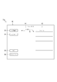
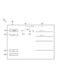
- the setting change screen 80 shown in FIG. 10 arbitrarily assigns the operation of the rotary plow 20 and the front loader 30 to the operation of the work implement operating tool 50, that is, arbitrarily associates the message ID of the signal transmitted from the signal transmission unit 60.
- Screen. The setting change screen 80 is displayed by appropriately operating the touch panel 70a of the communication terminal 70.
- the setting change screen 80 according to the present embodiment is configured so that an operation can be assigned to each work implement. In FIG. It has been described. On the setting change screen 80, an image 81 of the work implement operation tool 50, an operation name 82 of the work implement operation implement 50, an operation name 83 of the work implement operation 83, an enter button 84, a cancel button 85, and the like are displayed. In FIG. 10, some operations (operations of the lever 51 in an oblique direction) are omitted for convenience.
- the operation name 82 of the work implement operating tool 50 and the operation name 83 of the work implement are arranged side by side with each other.
- the operation name 83 of the work implement indicates the operation of the work implement assigned to the operation name 82 of the work implement operating tool 50 displayed on the left.
- the touch panel 70a is configured such that the operation name 83 of the work machine can be set by being appropriately operated.
- the decision button 84 is a button for reflecting the content assigned on the setting change screen 80 on the signal transmission unit 60.
- the setting change unit 72 transmits a signal for changing the setting of the signal transmission unit 60 (rewriting the information on the message ID stored in the signal transmission unit 60).
- the setting change unit 72 changes the signal transmitted from the signal transmission unit 60 to a signal corresponding to the content assigned on the setting change screen 80.
- the setting changing unit 72 associates the operation of the work implement operating tool 50 with the message ID of the signal transmitted from the signal transmitting unit 60.
- the rotary tillage device 20 performs the tilling operation.
- the setting of the signal transmission unit 60 is changed so as to transmit a message ID signal that can be started and stopped.
- the Cancel button 85 is a button for discarding the content assigned on the setting change screen 80.
- the cancel button 85 is touched, the setting change unit 72 does not change the setting of the signal transmission unit 60 and displays the screen displayed before the setting change screen 80.
- the operations of the rotary tillage device 20 and the front loader 30 can be assigned to the operation of the work implement operating tool 50 so that the operator can easily use it. Therefore, the operability of the work implement operating tool 50 can be improved.
- the setting of the setting change unit 72 is changed using the setting change screen 80, and the message ID of the signal transmitted from the signal transmission unit 60 is arbitrarily associated with the operation of the work implement operating tool 50.
- the same association as the above association can be applied to the translation unit 71.
- the communication terminal 70 arbitrarily associates the message ID of the signal transmitted from the translator 71 with the message ID of the signal received from the signal transmitter 60 (changes the correspondence).
- the communication terminal 70 reflects, for example, the content assigned on the setting change screen 80 in the translation unit 71 (rewrites information on the message ID stored in the storage device). Specifically, for example, when “tiling ON / OFF” is assigned to the operation of the “first switch” on the setting change screen 80 shown in FIG. 10, when the first switch 53 is pressed in the second state ( Strictly speaking, when the signal is received from the signal transmission unit 60), the setting of the translation unit 71 is changed so that the rotary plow 20 transmits a signal of a message ID that can execute the start and stop of the plowing operation. Thereby, communication terminal 70 arbitrarily associates the message ID of the signal transmitted from translation section 71 with the operation of work implement operating tool 50.
- the communication terminal 70 transmits the message ID of the signal transmitted from the translation unit 71 (the signal converted by the translation unit 71) to the message of the signal received from the signal transmission unit 60 in response to the operation of the work implement operating tool 50.
- the ID can be arbitrarily associated with the ID. According to this, since the operation of the rotary tillage device 20 and the front loader 30 can be assigned to the operation of the work implement operating tool 50 so that the worker can easily use the work implement, the operability of the work implement operating tool 50 is improved. Can be.
- the pattern transmission unit 73 operates the rotary tillage device 20 and the front loader 30 in accordance with a predetermined pattern operation.
- the operation of the predetermined pattern is an operation (special operation) different from a simple operation for the lever 51 or the like (for example, an operation of tilting the lever 51 forward once).
- the operation of the predetermined pattern includes a command operation, a continuation operation, an operation combining the command operation and the continuation operation, and the like.
- the command operation is a combination of operations on the lever 51 and the like (operation for transmitting a plurality of signals from the signal transmitting unit 60).
- the command operation is, for example, an operation of tilting the lever 51 in a predetermined order or simultaneously pressing a plurality of switches (for example, the first switch 53 and the second switch 54).
- the continuation operation is an operation of continuously operating one switch (for example, the first switch 53) for a predetermined time (operation of continuously transmitting the same signal from the signal transmission unit 60).
- an operation in which the command operation and the continuation operation are combined is, for example, an operation in which the lever 51 is moved rightward for a predetermined time and then leftward.
- the pattern transmission unit 73 includes a command transmission unit 73a and a continuation transmission unit 73b.
- the command transmission unit 73a operates the rotary tillage device 20 and the front loader 30 when a command operation (for example, an operation of tilting the lever 51 in the order of right, rear, rear right while pressing the first switch 53) is performed. It is.
- a command operation for example, an operation of tilting the lever 51 in the order of right, rear, rear right while pressing the first switch 53
- the signal transmission unit 60 sequentially transmits a plurality of signals in accordance with the command operation.
- the command transmission unit 73a starts processing by receiving a signal from the signal transmission unit 60.
- the command transmitting unit 73a when receiving the signal S1 corresponding to the front loader 30 from the signal transmitting unit 60, the command transmitting unit 73a checks a combination of the signal S1 received within a predetermined time (for example, the signal S1 received within 2 seconds). . Then, the command transmission unit 73a obtains information from the storage device or the like of the communication terminal 70 as appropriate to determine whether the combination of the signals S1 is registered in advance (whether the combination is a predetermined command operation). Determine whether or not.
- a predetermined time for example, the signal S1 received within 2 seconds.
- the command transmission unit 73a determines the operation associated with the combination of the signals S1. Then, the command transmitting unit 73a determines a message ID capable of executing the operation determined by the front loader 30, and transmits a signal S1 of the determined message ID. Further, when receiving the signal S2 corresponding to the rotary tilling device 20, the command transmitting unit 73a checks the combination of the signals S2, as in the case where the signal S1 is received, and outputs a message that allows the rotary tilling device 20 to execute an operation. An ID signal S2 is transmitted.
- the command transmission unit 73a can transmit a signal corresponding to the command operation to operate the rotary plow 20 and the front loader 30.
- the tilling of the rotary tilling device 20 is stopped after 10 seconds, and the non-working position (most (A raised position).
- the command transmission unit 73a not only the simple operation of tilting the lever 51 forward once but also the continuous operation (command operation) of tilting the lever 51 in a predetermined order (the command operation), the rotary tiller 20 and the front loader 30 can be used. Can be operated. Thereby, the operations of the rotary tillage device 20 and the front loader 30 can be assigned more to the operation of the work implement operating tool 50, and various operations can be performed with the work implement operating implement 50. Can be improved.
- the command setting screen 90 shown in FIG. 11 is a screen for arbitrarily assigning the operation of the rotary tiller 20 and the front loader 30 to the command operation (arbitrarily correlating the message ID of the signal).
- the command setting screen 90 is displayed by appropriately operating the touch panel 70a of the communication terminal 70.
- the command setting screen 90 according to the present embodiment is configured so that an operation can be assigned to each work implement.
- FIG. 11 a screen for assigning the operation of the rotary plow 20 to the operation of the work implement operating tool 50 is shown. It has been described.
- On the command setting screen 90 an operation content 91, an operation name 92 of a work machine, an input start button 93, an input end button 94, an enter button 95, a cancel button 96, and the like are displayed.
- the operation content 91 indicates a command operation (combination of signals) on the work implement operating tool 50.
- the operation content 91 and the operation name 92 of the work implement are arranged side by side with each other.
- the operation name 92 of the work implement indicates the operation of the work implement assigned to the operation content 91 displayed on the left.
- the touch panel 70a is configured so that the operation name 92 of the work machine can be set by being operated as appropriate. Note that FIG. 11 and FIG. 12, which will be described later, show a state in which a predetermined operation (“Motion 1” and “Motion 2”) is performed when the operation described in the operation content 91 is performed. .
- the input start button 93 and the input end button 94 are used to set operation contents 91.
- communication terminal 70 accepts an operation of work implement operating tool 50. That is, the communication terminal 70 stores the signals from the signal transmission unit 60 in order, and causes the operation content 91 to appropriately display the operation corresponding to the signal. As shown in FIG. 12, for example, when the lever 51 is operated in the order of left and right, the communication terminal 70 displays the operation in the operation content 91.
- the input end button 94 is touched, the communication terminal 70 ends accepting the operation of the work implement operating tool 50.
- On the command setting screen 90 by assigning an operation (“motion 2”) to be assigned to the operation content 91 (“ ⁇ ⁇ ”) set in this way to the operation name 92, an arbitrary operation can be assigned to the command operation. it can.
- the determination button 95 is a button for reflecting the content assigned on the command setting screen 90 to the command transmission unit 73a.
- the communication terminal 70 stores the operation content 91 and the operation name 92 of the work machine in the storage device in association with each other. Thereby, the communication terminal 70 can assign the operations of the rotary tiller 20 and the front loader 30 to the command operation (combination of signals) arbitrarily set by the operator.
- the cancel button 96 is a button for discarding the content assigned on the command setting screen 90.
- the communication terminal 70 displays the screen displayed before the command setting screen 90 without storing in the storage device.
- the operation of the rotary tilling device 20 and the front loader 30 can be assigned to the command operation (combination of signals) of the work implement operation tool 50 so that the operator can easily use the work implement.
- the operability of the tool 50 can be improved.
- the continuous transmission unit 73b is configured to continuously operate the rotary tillage device 20 and the front loader 30 when a continuous operation is performed (for example, when the first switch 53 is pressed for 3 seconds).
- the continuation transmission unit 73b starts processing by receiving a signal from the signal transmission unit 60.
- the continuous transmitting unit 73b when receiving the signal S1 corresponding to the front loader 30 from the signal transmitting unit 60, the continuous transmitting unit 73b measures the time during which the signal S1 is received. Then, when the measured time exceeds a predetermined time (for example, 3 seconds), the continuous transmission unit 73b performs a continuous operation with the work implement operating tool 50 (for example, the first switch 53 is pressed and held for 3 seconds). J). In this case, the continuation transmitting unit 73b starts transmitting the same signal S1 as the received signal S1 (the signal of the message ID associated with the operation of the work implement operating tool 50). Thereafter, the continuous transmission unit 73b continuously transmits the signal S1 regardless of whether or not the signal S1 is received from the signal transmission unit 60.
- a predetermined time for example, 3 seconds
- the continuous transmission unit 73b performs a continuous operation with the work implement operating tool 50 (for example, the first switch 53 is pressed and held for 3 seconds). J).
- the continuation transmitting unit 73b starts
- the continuation transmitting unit 73b performs the continuation operation when the signal S2 corresponding to the rotary tilling device 20 is received from the signal transmitting unit 60, similarly to the case where the signal S1 corresponding to the front loader 30 is received. Is determined.
- the continuation transmitting unit 73b starts transmitting the same signal S2 as the received signal S2, regardless of whether the signal S2 has been received from the signal transmitting unit 60. The transmission of the signal S2 is continuously performed.
- the operations of the rotary tillage device 20 and the front loader 30 assigned to the operation are continued. It can be carried out. Thereby, the operation of the rotary tillage device 20 and the front loader 30 can be continued without the operator continuing to operate the work implement operating tool 50. For this reason, convenience can be improved.
- the continuous transmission unit 73b stops transmitting a signal when a predetermined condition is triggered (for example, when the first switch 53 is pressed again for three seconds).
- the work implement operating tool 50 is configured to be capable of inputting a predetermined direction, and the front loader 30 and the rotary tilling device 20 (other than the front loader 30) according to the input direction.
- the front loader 30 and the rotary plow 20 provided at the lever 51 and capable of operating at least the rotary plow 20 of the front loader 30 and the rotary plow 20.
- a first switch 53 to a fourth switch 56 (first operation unit).
- the rotary tillage device 20 can be operated in addition to the front loader 30, so that the convenience can be improved.
- the apparatus further comprises a changeover switch 58 (switching section) that can switch between a state in which the front loader 30 can be operated and a state in which the rotary plow 20 can be operated.
- a changeover switch 58 switching section
- a dial 57 (second operation unit) that can operate the front loader 30 and the rotary tillage device 20 according to an operation amount is further provided.
- the operation amounts of the front loader 30 and the rotary tilling device 20 can be adjusted according to the operation amount of the dial 57, so that the operations of the front loader 30 and the rotary tilling device 20 can be finely controlled. Operability can be improved.
- the work implement operating system 40 includes a work implement operating tool 50, a signal transmitting unit 60 that transmits a signal corresponding to an operation of the work implement operating tool 50, the signal transmitting unit 60, and the front And a communication terminal 70 (management unit) that manages communication with the loader 30 and / or the rotary plow 20.
- the communication terminal 70 includes a translator 71 that converts a signal received from the signal transmitter 60 into a signal corresponding to the front loader 30 and / or the rotary tilling device 20 and transmits the signal. .
- the communication terminal 70 can change the signal received from the signal transmission unit 60 and the signal converted by the translation unit 71 into an arbitrary correspondence.
- the communication terminal 70 changes the setting of the signal transmission unit 60 to change the correspondence between the operation of the work implement operating tool 50 and the signal transmitted from the signal transmission unit 60 in response to the operation. It has a setting change unit 72 for changing.
- the signal transmitted from the signal transmission unit 60 can be changed as appropriate. Accordingly, a signal corresponding to the front loader 30 or the like can be transmitted from the signal transmission unit 60, and thus the front loader 30 and the rotary tilling device 20 can be operated.
- the communication terminal 70 can change an operation of the work implement operating tool 50 set by the setting change unit 72 and a signal transmitted from the signal transmission unit 60 in accordance with the operation into an arbitrary correspondence relationship. is there.
- the communication terminal 70 further includes a pattern transmitting unit 73 that transmits a signal determined according to the predetermined pattern when receiving a signal of a predetermined pattern from the signal transmitting unit 60.
- the front loader 30 and the rotary tilling device 20 can be operated not only by simply inputting the lever 51 or the like, but also by performing a predetermined operation with the work implement operating tool 50. Performance can be improved.
- the pattern transmitting unit 73 receives a signal of a predetermined combination including a plurality of signals from the signal transmitting unit 60, the pattern loader 73 and / or the rotary plow 20 determined according to the combination are received. And a command transmitting unit 73a for transmitting a signal corresponding to the predetermined operation.
- the front loader 30 and the rotary tilling device 20 can be operated according to not only one signal but also a plurality of signals. Thereby, the operations of the front loader 30 and the rotary tiller 20 can be assigned to a plurality of signals in addition to one signal, so that operability can be improved.
- the pattern transmitting unit 73 continues transmitting a signal corresponding to the signal even when the signal is not received. 73b.
- the front loader 30 and the rotary tillage device 20 can be automatically and continuously operated, thereby improving convenience. Can be.
- the work implement operating tool 50 includes a lever 51 capable of inputting a predetermined direction, and a first switch 53 provided on the lever 51 and capable of operating the rotary tilling device 20 (another work implement different from the front loader 30). To a fourth switch 56 (switch).
- the rotary tillage device 20 according to the present embodiment is an embodiment of another working machine according to the present invention.
- the first switch 53 to the fourth switch 56 according to the present embodiment are one embodiment of the first operation unit and the switch according to the present invention.
- the changeover switch 58 according to the present embodiment is an embodiment of the switching unit according to the present invention.
- the dial 57 according to the present embodiment is an embodiment of the second operation unit according to the present invention.
- the communication terminal 70 according to the present embodiment is an embodiment of the management unit according to the present invention.
- Patent Document 1 Japanese Patent Application Laid-Open No. 2013-226872.
- the work implement operation system described in Patent Document 1 includes a work implement operation tool (control lever) for operating a front loader (work implement).
- the work implement operating tool is configured to be operable (swing) in the front-rear direction and the left-right direction.
- the boom of the front loader is raised and lowered by operating the work equipment operation tool in the front-back direction, and the bucket of the front loader is rocked by operating the work equipment operation tool in the left and right direction. Can be.
- a work machine (a front loader in the example described in Patent Document 1) is operated in accordance with an operation of a work machine operation tool in front, rear, left, and right (four directions). Only four types of operations can be performed. As described above, the number of operations of the work implement is limited depending on the type of operation direction of the work implement operating tool, and it is difficult to improve operability.
- the present invention has been made in view of the above situation, and a problem to be solved is to provide a work machine operation system capable of improving operability.
- the work implement operating tool 50 is configured to be capable of inputting a predetermined direction, and operates the front loader 30 and the rotary tilling device 20 (work implement including at least the front loader 30) according to the input direction.
- a work implement operating tool 50 including a possible lever 51, and a first switch 53 to a fourth switch 56 (first operating section) provided on the lever 51, and a signal corresponding to the operation of the work implement operating tool 50 And a pattern for transmitting a signal determined according to the predetermined pattern to the front loader 30 and the rotary tilling device 20 when a signal of a predetermined pattern is received from the signal transmission unit 60. And a transmitting unit 73.
- the front loader 30 can be operated not only when a simple operation is performed by the lever 51 or the like but also when a predetermined operation is performed using the work implement operating tool 50, thereby improving operability. Can be.
- the signal transmitted from the signal transmission unit 60 does not correspond to the front loader 30 and the rotary tillage device 20
- the signal is appropriately converted by the translation unit 71, and the front loader 30 And the rotary tillage device 20 can be operated.
- the communication terminal 70 (first operation terminal) in which the translation unit 71 is mounted and which can change a signal received from the signal transmission unit 60 and a signal converted by the translation unit 71 into an arbitrary correspondence relationship. It is further equipped.
- a setting changing unit 72 that changes the correspondence between the operation of the work implement operating tool 50 and the signal transmitted from the signal transmitting unit 60 in response to the operation. Is further provided.
- the signal transmitted from the signal transmission unit 60 can be changed as appropriate. Thereby, the signal corresponding to the front loader 30 and the rotary tilling device 20 can be transmitted from the signal transmission unit 60.
- the setting change unit 72 is mounted, and the operation of the work implement operating tool 50 set by the setting change unit 72 and the signal transmitted from the signal transmission unit 60 in response to the operation have an arbitrary correspondence. It further includes a changeable communication terminal 70 (second operation terminal).
- the work implement operating tool 50 further includes a dial 57 (second operating section) that can operate the front loader 30 and the rotary tillage device 20 according to the amount of operation.
- the operation amounts of the front loader 30 and the rotary tilling device 20 can be adjusted according to the operation amount of the dial 57, so that the operations of the front loader 30 and the rotary tilling device 20 can be finely controlled. Operability can be further improved.
- the pattern transmission unit 73 receives a signal of a predetermined combination including a plurality of signals from the signal transmission unit 60, a predetermined combination of the front loader 30 and the rotary plow 20 determined according to the combination is received.
- a command transmission unit 73a that transmits a signal corresponding to the operation is provided.
- the front loader 30 and the rotary tilling device 20 can be operated according to not only one signal but also a plurality of signals. Thereby, since the operations of the front loader 30 and the rotary tillage device 20 can be assigned to a plurality of signals in addition to one signal, the operability can be further improved.
- the pattern transmitting unit 73 continues transmitting a signal corresponding to the signal even when the signal is not received. 73b.
- the front loader 30 and the rotary tillage device 20 according to the present embodiment are one embodiment of a working machine including at least the front loader according to the present invention.
- the first switch 53 to the fourth switch 56 according to the present embodiment are one embodiment of the first operation unit according to the present invention.
- the communication terminal 70 according to the present embodiment is an embodiment of the first operation terminal and the second operation terminal according to the present invention.
- the dial 57 according to the present embodiment is an embodiment of the second operation unit according to the present invention.
- the rotary tilling device 20 has been described as an example of a working machine other than the front loader 30.
- the working machine operating tool 50 can operate a working machine other than the rotary tilling device 20. It is.
- the work implement operating tool 50 can also operate a boom sprayer, a spreader, a grab of the front loader 30, a harrow, a seaming machine, a plow, a seeder, and the like.
- the work implement operating tool 50 can perform, for example, start and end of spraying of pesticides, folding and opening of arms, adjustment of spraying height, and the like. Further, when the spreader is operated, the work implement operating tool 50 can perform, for example, start and end of fertilizer application, increase / decrease of the application amount, and the like.
- the grab of the front loader 30 the work implement operating tool 50 can open and close the grab, for example.
- the work implement operating tool 50 can perform, for example, folding and unfolding of the leveling plate, raising and lowering of the porch, and the like.
- the work implement operating tool 50 can perform, for example, adjustment (offset) of the movement position and the work position when operating the blasting machine.
- the work implement operating tool 50 can perform, for example, switching between right alignment and left alignment.
- the work implement operating tool 50 can start and end spraying of seeds and fertilizers, for example.
- the lever 51 can be tilted in the front-rear direction, the left-right direction, and the oblique direction.
- the tilt direction of the lever 51 is not limited to this, and it is sufficient that the lever 51 can be tilted in at least one direction.
- the work implement operating tool 50 adjusts the operation amount of the work implement using the dial 57.
- the means for adjusting the operation amount is not limited to the dial 57, and may be, for example, a slide amount in a predetermined direction. May be a slide switch or the like, the amount of operation of which can be adjusted according to the above.
- the dial 57 is provided on the lever 51, but the arrangement of the dial 57 is not limited to this.
- the dial 57 may be provided on the box 52 or the like.
- the dial 57 is used in the operation of the rotary tilling device 20, but is not limited thereto, and may be used in the operation of the front loader 30.
- the changeover switch 58 is configured by a toggle switch, the type of the changeover switch 58 is not limited to this, and may be, for example, a push button switch.
- the changeover switch 58 is provided in the box 52, but the arrangement of the changeover switch 58 is not limited to this.
- the changeover switch 58 may be provided in the lever 51 or the like.
- the translation unit 71, the setting change unit 72, the command transmission unit 73a, and the continuation transmission unit 73b are assumed to be mounted on the communication terminal 70.
- the device on which the unit 73b is mounted is not limited to the communication terminal 70, but can be mounted on various devices (for example, a smartphone or the like).
- the setting change unit 72 changes the setting (signal) of the signal transmission unit 60. However, if the signal from the signal transmission unit 60 can operate the rotary plow 20 and the front loader 30, the setting change unit 72 changes the setting. The object to be changed is not limited to the signal transmission unit 60.
- the setting change unit 72 changes the settings of the microcomputers 24 and 34 of the rotary tillage device 20 and the front loader 30 so that the signal from the signal transmission unit 60 causes the rotary tillage device 20 and the front loader 30 to operate. You may.
- the various functions of the communication terminal 70 can be executed simultaneously.
- the communication terminal 70 can simultaneously execute the processes of the translation unit 71 and the command transmission unit 73a of the pattern transmission unit 73, for example, as follows. That is, when receiving the signal from the signal transmitting unit 60, the command transmitting unit 73a determines whether a command operation has been performed based on a combination of the signals. When determining that a command operation has been performed, the command transmitting unit 73a converts the signal received from the signal transmitting unit 60 into a message ID signal of an operation assigned to the command operation, and transmits the signal to the translating unit 71.
- the translation unit 71 further converts the signal received from the command transmission unit 73a (the signal converted by the command transmission unit 73a) into a signal corresponding to the rotary tilling device 20 and the front loader 30, and transmits the signal.
- the present invention can be applied to the technology of a work implement operating tool and a work implement operation system for operating a work implement attached to a work vehicle.
Landscapes
- Engineering & Computer Science (AREA)
- Transportation (AREA)
- General Physics & Mathematics (AREA)
- Automation & Control Theory (AREA)
- Chemical & Material Sciences (AREA)
- Combustion & Propulsion (AREA)
- Physics & Mathematics (AREA)
- Mechanical Engineering (AREA)
- Mining & Mineral Resources (AREA)
- Civil Engineering (AREA)
- General Engineering & Computer Science (AREA)
- Structural Engineering (AREA)
- Lifting Devices For Agricultural Implements (AREA)
- Operation Control Of Excavators (AREA)
Abstract
利便性を向上させることが可能な作業機操作具を提供する。 所定方向を入力可能に構成され、入力された方向に応じて、フロントローダ及びロータリ耕耘装置のうち、少なくともフロントローダを動作可能なレバー51と、レバー51に設けられ、フロントローダ及びロータリ耕耘装置のうち、少なくともロータリ耕耘装置20を動作可能な第一スイッチ53から第四スイッチ56までと、フロントローダ30を動作可能な状態と、ロータリ耕耘装置20を動作可能な状態と、を切り替え可能な切替スイッチ58と、を具備する。
Description
本発明は、作業車に取り付けられる作業機を操作するための作業機操作具及び作業機操作システムの技術に関する。
従来、作業車に取り付けられる作業機を動作させるための作業機操作具及び作業機操作システムの技術は公知となっている。例えば、特許文献1に記載の如くである。
特許文献1に記載の作業機操作具(コントロールレバー)は、フロントローダ(作業機)を動作させるためのものであり、前後方向及び左右方向へ操作(揺動)可能に構成される。作業機操作具は、前後方向に操作されることでフロントローダのブームを昇降させ、左右方向に操作されることでフロントローダのバケットを揺動させることができる。
しかし、特許文献1に記載の作業機操作具は、フロントローダだけしか動作させることができない。このため、特許文献1においては作業機操作具の用途が限られてしまい、利便性を向上させることが困難となってしまう可能性があった。
本発明は、以上の如き状況を鑑みてなされたものであり、その解決しようとする課題は、利便性を向上させることが可能な作業機操作具及び作業機操作システムを提供するものである。
本発明の解決しようとする課題は以上の如くであり、次にこの課題を解決するための手段を説明する。
即ち、本発明の作業機操作具は、所定方向を入力可能に構成され、入力された方向に応じて少なくともフロントローダを含む作業機を動作可能なレバーと、前記レバーに設けられる第一操作部と、を具備するものである。
また、本発明の作業機操作具において、前記レバーは、少なくともフロントローダを動作可能であり、前記第一操作部は、少なくとも前記フロントローダとは異なる他の作業機を動作可能である。
また、本発明の作業機操作具は、前記フロントローダを動作可能な状態と、前記他の作業機を動作可能な状態と、を切り替え可能な切替部をさらに具備するものである。
また、本発明の作業機操作具は、操作量に応じて前記フロントローダ及び前記他の作業機を動作可能な第二操作部をさらに具備するものである。
また、本発明の作業機操作システムは、前記作業機操作具と、前記作業機操作具の操作に応じた信号を発信する信号発信部と、前記信号発信部と前記フロントローダ及び/又は前記他の作業機との通信を管理する管理部と、を具備するものである。
また、本発明の作業機操作システムにおいて、前記管理部は、前記信号発信部から受信した信号を、前記フロントローダ及び/又は前記他の作業機に対応した信号に変換して発信する翻訳部を具備するものである。
また、本発明の作業機操作システムにおいて、前記管理部は、前記信号発信部から受信する信号と、前記翻訳部が変換する信号と、を任意な対応関係に変更可能である。
また、本発明の作業機操作システムにおいて、前記管理部は、前記信号発信部の設定を変更することにより、前記作業機操作具の操作と当該操作に応じて前記信号発信部から発信される信号との対応関係を変更する設定変更部を具備するものである。
また、本発明の作業機操作システムにおいて、前記管理部は、当該設定変更部が設定する前記作業機操作具の操作と当該操作に応じて前記信号発信部から発信される信号とを任意な対応関係に変更可能である。
また、本発明の作業機操作システムにおいて、前記管理部は、前記信号発信部から所定のパターンの信号を受信した場合、当該所定のパターンに応じて定められた信号を発信するパターン発信部を具備するものである。
また、本発明の作業機操作システムにおいて、前記パターン発信部は、前記信号発信部から複数の信号からなる所定の組み合わせの信号を受信した場合、当該組み合わせに応じて定められた前記フロントローダ及び/又は前記他の作業機の所定の動作に対応した信号を発信するコマンド発信部を具備するものである。
また、本発明の作業機操作システムにおいて、前記パターン発信部は、前記信号発信部から所定時間継続して同一の信号を受信した場合、当該信号を受信しなくなっても当該信号に応じた信号の発信を継続する継続発信部を具備するものである。
また、本発明の作業機操作具は、所定方向を入力可能なレバーと、前記レバーに設けられ、フロントローダとは異なる他の作業機を動作可能なスイッチと、を具備するものである。
また、本発明の作業機操作システムは、前記作業機操作具と、前記作業機操作具の操作に応じた信号を発信する信号発信部と、前記信号発信部から所定のパターンの信号を受信した場合、当該所定のパターンに応じて定められた信号を前記作業機へ発信するパターン発信部と、を具備するものである。
また、本発明の作業機操作システムは、前記信号発信部から受信した信号を、前記作業機に対応した信号に変換して発信する翻訳部をさらに具備するものである。
また、本発明の作業機操作システムは、前記翻訳部が実装され、前記信号発信部から受信する信号と、前記翻訳部が変換する信号と、を任意な対応関係に変更可能な第一操作端末をさらに具備するものである。
また、本発明の作業機操作システムは、前記信号発信部の設定を変更することにより、前記作業機操作具の操作と当該操作に応じて前記信号発信部から発信される信号との対応関係を変更する設定変更部をさらに具備するものである。
また、本発明の作業機操作システムは、前記設定変更部が実装され、当該設定変更部が設定する前記作業機操作具の操作と当該操作に応じて前記信号発信部から発信される信号とを任意な対応関係に変更可能な第二操作端末をさらに具備するものである。
また、本発明の作業機操作システムにおいて、前記作業機操作具は、操作量に応じて前記作業機を動作可能な第二操作部をさらに具備するものである。
また、本発明の作業機操作システムにおいて、前記パターン発信部は、前記信号発信部から複数の信号からなる所定の組み合わせの信号を受信した場合、当該組み合わせに応じて定められた前記作業機の所定の動作に対応した信号を発信するコマンド発信部を具備するものである。
本発明の効果として、以下に示すような効果を奏する。
本発明の作業機操作具においては、利便性を向上させることができる。
本発明の作業機操作具においては、必要に応じてフロントローダ及び他の作業機を動作させることができる。
本発明の作業機操作具においては、操作性を向上させることができる。
本発明の作業機操作システムにおいては、管理部を用いて作業機操作具とフロントローダ及び/又は他の作業機との通信を管理することができる。
本発明の作業機操作システムにおいては、信号発信部から発信される信号がフロントローダ及び他の作業機に対応していない場合でも、当該フロントローダ及び他の作業機を動作させることができる。
本発明の作業機操作システムにおいては、操作性を向上させることができる。
本発明の作業機操作システムにおいては、信号発信部からフロントローダ及び/又は他の作業機に対応した信号を発信させることができる。
本発明の作業機操作システムにおいては、利便性を向上させることができる。
本発明の作業機操作システムにおいては、信号発信部から発信される信号が作業機に対応していない場合でも、当該作業機を動作させることができる。
本発明の作業機操作システムにおいては、操作性をより向上させることができる。
本発明の作業機操作システムにおいては、信号発信部から作業機に対応した信号を発信させることができる。
以下では、図中の矢印U、矢印D、矢印F、矢印B、矢印L及び矢印Rで示した方向を、それぞれ上方向、下方向、前方向、後方向、左方向及び右方向と定義して説明を行う。
まず、図1を用いてトラクタ1の全体構成について説明する。
トラクタ1は、主として機体フレーム2、前輪3、後輪4、エンジン5、ボンネット6、変速装置7、油圧昇降装置8、キャビン9、ステアリングホイール10、座席11、ロータリ耕耘装置20及びフロントローダ30を具備する。
機体フレーム2は、その長手方向を前後方向に向けて配置される。機体フレーム2の前部はフロントアクスル機構(不図示)を介して左右一対の前輪3に支持される。機体フレーム2の後部にはミッションケースに収容された変速装置7が設けられる。変速装置7の後部はリアアクスル機構(不図示)を介して左右一対の後輪4に支持される。
機体フレーム2の前部にはエンジン5が設けられる。エンジン5はボンネット6に覆われる。エンジン5の動力は、変速装置7で変速された後、前記フロントアクスル機構を経て前輪3に伝達可能とされると共に、リアアクスル機構を経て後輪4に伝達可能とされる。エンジン5の動力によって前輪3及び後輪4が回転駆動され、トラクタ1は走行することができる。
また、エンジン5の動力は、変速装置7で変速された後、PTO軸に伝達可能とされる。本実施形態において、当該PTO軸には、ロータリ耕耘装置20が連結されている。ロータリ耕耘装置20は、トラクタ1の後部に配置され、主として伝動ケース21、ロータリ軸22、複数の爪23及びマイコン24(図2参照)を具備する。伝動ケース21は、PTO軸からの動力をロータリ軸22に伝達することで、ロータリ軸22を回転させる。これにより、ロータリ耕耘装置20は、複数の爪23を回転させて圃場等を耕すことができる。また、ロータリ耕耘装置20は、油圧昇降装置8によって昇降可能に構成される。マイコン24は、ロータリ耕耘装置20の動作を制御するものである。マイコン24については後述する。
また、トラクタ1の前部には、フロントローダ30が装着される。フロントローダ30は、主として支持フレーム31、ブーム32、バケット33及びマイコン34(図2参照)を具備する。支持フレーム31は、機体フレーム2に固定される。ブーム32は、支持フレーム31に回動可能に連結され、前方に向かって延びるように配置される。バケット33は、ブーム32の前端部に回動可能に連結される。ブーム32はブームシリンダ32aを伸縮させることで、支持フレーム31に対して回動させることができる。バケット33はバケットシリンダ33aを伸縮させることで、ブーム32に対して回動させることができる。このように、フロントローダ30は、ブーム32及びバケット33を適宜回動させながら土砂の運搬作業等を行うことができる。マイコン34は、フロントローダ30の動作を制御するものである。マイコン34については後述する。
また、トラクタ1の前後中途部(エンジン5の後方)にはキャビン9が設けられる。キャビン9の内部には、作業者が搭乗する居住空間9aが形成される。居住空間9aには、前輪3の切れ角を調節するためのステアリングホイール10、作業者が着座するための座席11等が配置される。
また、居住空間9aには、ロータリ耕耘装置20及びフロントローダ30を動作させるための作業機操作具50、及びトラクタ1に設けられる機器と適宜通信可能な通信端末70が配置される。作業機操作具50は、座席11の右方に設けられる。通信端末70は、座席11の前方に配置されるメーターパネル(不図示)とは別に、当該メータパネルの上方に配置される。
次に、図2から図5までを参照して、作業機操作具50の操作に応じてロータリ耕耘装置20及びフロントローダ30を動作させるための作業機操作システム40の構成について説明する。
図2に示す作業機操作システム40は、作業機操作具50及び通信端末70を具備する。
図2及び図3に示す作業機操作具50は、作業者が操作するためのものである。作業機操作具50は、レバー51、ボックス52、第一スイッチ53、第二スイッチ54、第三スイッチ55、第四スイッチ56、ダイヤル57、切替スイッチ58、検出部59(図4参照)及び信号発信部60を具備する。
レバー51は、傾動操作によって所定の方向を入力するためのものである。本実施形態に係るレバー51は、前後方向、左右方向及び斜め方向(左前方向、左後方向、右前方向及び右後方向)を入力可能に構成される。レバー51は、本体部51a、グリップ51b及びブーツ51cを具備する。
本体部51aは、上下方向に延びた略直方体状に形成される。本体部51aは、所定の支持機構に支持されることにより、前後方向、左右方向及び斜め方向に揺動自在に設けられる。また、本体部51aは、バネ等で付勢されることにより、元の位置(どの方向にも揺動していない位置)に戻るように構成される。
グリップ51bは、作業者が握る部分であると共に、本体部51aの上部である。グリップ51bは、本体部51aの他の部分よりも前後方向幅が長くなるように形成されると共に、上面が上方へ膨らんだ曲面状に形成される。
ブーツ51cは、本体部51aの下部を覆うものである。ブーツ51cは、ゴム等の弾性体によって構成される。
ボックス52は、略箱状の部材である。ボックス52には、本体部51aを支持する前記支持機構や後述する信号発信部60等が収容される。
第一スイッチ53から第四スイッチ56までは、押下操作するための押しボタン式のスイッチである。第一スイッチ53から第四スイッチ56までは、レバー51に設けられる。より詳細には、第一スイッチ53及び第二スイッチ54は、グリップ51bの左側に前後に並ぶように設けられる。第三スイッチ55及び第四スイッチ56は、グリップ51bの前側に左右に並ぶように設けられる。
ダイヤル57は、回動操作するための操作具である。ダイヤル57は、自身を無段階に(アナログ的に)回動操作可能に構成される。ダイヤル57は、レバー51(第一スイッチ53及び第二スイッチ54の下方)に設けられる。
切替スイッチ58は、作業機操作具50を用いてフロントローダ30を動作可能な第一状態と、作業機操作具50を用いてロータリ耕耘装置20(フロントローダ30以外の作業機)を動作可能な第二状態と、を切り替えるためのものである。切替スイッチ58は、ボックス52の左側に設けられる。本実施形態に係る切替スイッチ58は、上方に倒された状態と、下方に倒された状態と、を切替可能なトグルスイッチによって構成される。なお、本実施形態に係る切替スイッチ58は、上方に倒されると(図3に示す状態となると)、第一状態に切り替えることができる。また、切替スイッチ58は、下方に倒されると、第二状態に切り替えることができる。
図4に示す検出部59は、レバー51等が操作されたことを検出するためのものである。検出部59は、ポテンショメータ59a、第一スイッチ検出部59b、第二スイッチ検出部59c、第三スイッチ検出部59d、第四スイッチ検出部59e、ロータリエンコーダ59f及び切替スイッチ検出部59gを具備する。
ポテンショメータ59aは、レバー51の入力方向に応じて複数設けられ、当該レバー51の揺動操作を検出するものである。第一スイッチ検出部59bから第四スイッチ検出部59eまでは、第一スイッチ53から第四スイッチ56までの押下操作を検出するものである。ロータリエンコーダ59fは、ダイヤル57の回動操作量を検出するものである。切替スイッチ検出部59gは、切替スイッチ58の切替操作を検出するものである。
信号発信部60は、レバー51等の操作に応じた信号、すなわち、レバー51等がどのように操作されたのかを識別可能な信号を発信するためのものである。信号発信部60は、レバー51等の操作に対応付けられたメッセージIDの信号を発信する。信号発信部60は、マイコン等によって構成される。信号発信部60は、検出部59と接続され、検出部59から検出結果に関する信号を受信可能に構成される。これにより、信号発信部60は、検出部59の検出結果(ポテンショメータ59a等の検出結果)を取得可能に構成される。また、信号発信部60は、所定の電源Pと接続され、当該電源Pからの電力供給によって動作する。
また、図2に示すように、信号発信部60は、CAN(Controller Area Network)等の車載ネットワークNに接続される。本実施形態に係る車載ネットワークNには、信号発信部60の他に、後述する通信端末70、ロータリ耕耘装置20のマイコン24及びフロントローダ30のマイコン34が接続されている。信号発信部60は、レバー51等が操作されると(検出部59から検出結果を取得すると)、当該操作に応じた信号を車載ネットワークNを介して発信することができる。
また、ロータリ耕耘装置20のマイコン24は、所定の信号のメッセージIDと、ロータリ耕耘装置20の動作と、を互いに関連付けて記憶している。また、フロントローダ30のマイコン34は、所定の信号のメッセージIDと、フロントローダ30の動作と、を互いに関連付けて記憶している。これにより、マイコン24・34は、受信した信号のメッセージIDに応じて、決められた動作を実行することができる。具体的には、例えば、ロータリ耕耘装置20のマイコン24は、「1」というメッセージIDに複数の爪23を回転させるという動作を関連付けて記憶していた場合、「1」というメッセージIDの信号を受信すると、当該メッセージIDに応じて複数の爪23を回転させることができる。
図2及び図5に示す通信端末70は、信号発信部60と、ロータリ耕耘装置20及びフロントローダ30のマイコン24・34と、の通信を管理するものである。通信端末70は、主としてCPU等の演算処理装置、RAMやROM等の記憶装置、並びにタッチパネル70a(図2参照)等の入出力装置等により構成される。通信端末70は、アプリケーションや種々の情報を前記記憶装置に格納しており、当該アプリケーションや種々の情報を演算処理装置で読み込んで処理することで、種々の処理を行うことができる。通信端末70は、翻訳部71、設定変更部72及びパターン発信部73を具備する。
翻訳部71は、通信端末70にインストールされたアプリケーションである。翻訳部71は、信号発信部60から受信した信号を適宜変換することで、ロータリ耕耘装置20及びフロントローダ30を動作させるものである。翻訳部71の処理については後述する。
設定変更部72は、通信端末70にインストールされたアプリケーションである。設定変更部72は、信号発信部60から発信される信号のメッセージIDを変更するものである。設定変更部72の処理については後述する。
パターン発信部73は、所定のパターンの操作に応じてロータリ耕耘装置20及びフロントローダ30を動作させるものである。パターン発信部73の処理については後述する。
次に、図3、図4及び図6を参照して、作業機操作具50を用いてロータリ耕耘装置20及びフロントローダ30を動作させる手順について説明する。
図3に示す作業機操作具50は、切替スイッチ58を適宜切り替えることによって第一状態及び第二状態を切り替えることができる。
具体的には、切替スイッチ58が上方へ倒されると、図4に示す切替スイッチ検出部59gは、当該操作を検出し、当該検出結果を信号発信部60へ発信する。これにより、信号発信部60は、作業機操作具50を第一状態に切り替える。
第一状態において、信号発信部60は、レバー51や第一スイッチ53等の操作に応じて発信する信号のメッセージIDを、フロントローダ30に対応するように、すなわち、フロントローダ30のマイコン34が識別可能なメッセージIDとなるように切り替える。これにより、信号発信部60は、自身が発信する信号を、フロントローダ30に対応する信号S1に切り替える。
図6に示すように、信号発信部60は、こうして切り替えた第一状態においてレバー51や第一スイッチ53等が操作されると、当該操作に応じて信号S1を車載ネットワークNに接続された装置にブロードキャストする。すなわち、信号発信部60は、フロントローダ30のマイコン34、ロータリ耕耘装置20のマイコン24及び通信端末70に信号S1を発信する。
フロントローダ30のマイコン34は、当該信号S1を受信すると、当該信号S1のメッセージIDに応じてフロントローダ30を動作させる(例えば、ブーム32を回動させる)。これにより、作業機操作具50は、レバー51や第一スイッチ53等の操作に応じて、フロントローダ30を動作させることができる。
なお、信号S1はフロントローダ30に対応した信号であるため、ロータリ耕耘装置20のマイコン24及び通信端末70は、当該信号S1を受信しても動作することはない。こうして、作業機操作具50は、第一状態においてフロントローダ30のみを動作させることができる。
また、切替スイッチ58が下方へ倒されると、信号発信部60は、作業機操作具50を第二状態に切り替える。第二状態において、信号発信部60は、レバー51や第一スイッチ53等の操作に応じて発信する信号を、ロータリ耕耘装置20に対応する信号S2に切り替える。図7に示すように、信号発信部60は、こうして切り替えた第二状態においてレバー51や第一スイッチ53等が操作されると、当該操作に応じて信号S2を発信する。
ロータリ耕耘装置20のマイコン24は、当該信号S2を受信すると、当該信号S2のメッセージIDに応じてロータリ耕耘装置20を動作させる(例えば、複数の爪23を回転させる)。これにより、作業機操作具50は、レバー51や第一スイッチ53等の操作に応じて、ロータリ耕耘装置20を動作させることができる。
また、信号発信部60は、第二状態においてダイヤル57が回動操作されると、ダイヤル57の回動操作量に応じた信号S2を発信する。これにより、ロータリ耕耘装置20の動作量を調整することができる。具体的には、ダイヤル57を回動操作することで、ロータリ耕耘装置20による耕耘の深さを調整することができる。このように、ダイヤル57によれば、ロータリ耕耘装置20の動作のオンオフだけではなく、ロータリ耕耘装置20の動作量も調整可能となる。このため、ロータリ耕耘装置20の動作を細かく制御可能となって、作業機操作具50の操作性を向上させることができる。
なお、第二状態において信号発信部60から発信される信号S2はロータリ耕耘装置20に対応した信号であるため、フロントローダ30のマイコン34及び通信端末70は、当該信号S2を受信しても動作することはない。こうして、作業機操作具50は、第二状態においてロータリ耕耘装置20のみを動作させることができる。
以上のように、切替スイッチ58によれば、レバー51や第一スイッチ53等の操作に応じて信号発信部60から発信される信号S1・S2を、フロントローダ30又はロータリ耕耘装置20のいずれかに対応した信号S1・S2に切り替えることができる。これにより、必要に応じてロータリ耕耘装置20及びフロントローダ30を動作させることができる。
次に、通信端末70のアプリケーション(翻訳部71、設定変更部72及びパターン発信部73)について説明する。
まず、図5に示す翻訳部71の処理について、図6及び図8を参照して説明する。
前述の如く、翻訳部71は、信号発信部60から受信した信号を適宜変換するものである。
ここで、例えば、トラクタ1に連結されるフロントローダ30が他の機種(別のフロントローダ30)に付け替えられた場合、当該フロントローダ30が信号発信部60から発信される信号に対応していない場合がある。より詳細には、他の機種に付け替えられたフロントローダ30のマイコン34が記憶しているメッセージIDと、信号発信部60から発信される信号のメッセージIDと、の対応関係がとれていない場合がある。この場合、信号発信部60から信号を発信したとしても、フロントローダ30を動作させることができなくなってしまう。翻訳部71は、信号発信部60から受信した信号を適宜変換することで、このような事態の発生を回避することができる。
具体的には、翻訳部71は、まず、所定の手段によってトラクタ1に連結されるフロントローダ30の機種を判別する。これにより、翻訳部71は、判別した機種に応じて、マイコン34が関連付けて記憶している信号のメッセージIDとフロントローダ30の動作との対応関係を判断することができる。なお、前記所定の手段としては、例えば、フロントローダ30が他の機種に付け替えられた際に発信されるマイコン34からの信号でフロントローダ30の機種を判別する手段や、タッチパネル70aによる操作でフロントローダ30の機種を手動で設定する手段等がある。
フロントローダ30の機種を判別した状態において、翻訳部71は、信号発信部60から信号S1を受信すると(図6参照)、当該信号S1に基づいて作業者が指示した(作業機操作具50の操作に対応付けられた)フロントローダ30の動作を判別する。
そして、図8に示すように、翻訳部71は、判別したフロントローダ30の機種に基づいて、当該フロントローダ30で作業者が指示した動作を実行可能なメッセージIDを判断する。その後、翻訳部71は、当該判断したメッセージIDの信号、すなわち付け替えられたフロントローダ30に対応する信号S3を発信する。
フロントローダ30のマイコン34は、当該信号S3を受信すると、当該信号S3のメッセージIDに応じてフロントローダ30を動作させる(例えば、ブーム32を回動させる)。
このように、翻訳部71によれば、信号発信部60から発信される信号S1がフロントローダ30に対応していなくても、当該信号発信部60から発信される信号S1とフロントローダ30とがあたかも対応しているように(擬似的に)作業機操作具50を操作することができる。これにより、信号発信部60から発信される信号S1に対応していないフロントローダ30を作業機操作具50で動作させることができる。
なお、翻訳部71から発信される信号S3は付け替えられたフロントローダ30に対応した信号であるため、ロータリ耕耘装置20のマイコン24は、当該信号S3を受信しても動作することはない。こうして、翻訳部71は、信号S3によりフロントローダ30のみを動作させることができる。
なお、翻訳部71は、ロータリ耕耘装置20が他の機種(別のロータリ耕耘装置20)に付け替えられた場合においても、フロントローダ30が他の機種に付け替えられた場合と同様の処理を行う。すなわち、翻訳部71は、ロータリ耕耘装置20の機種及び作業者が指示した動作を判別し、当該機種に基づいて作業者が指示した動作を実行可能なメッセージIDを判断し、付け替えられたロータリ耕耘装置20に対応する信号を発信する。
以上のように、翻訳部71によれば、信号発信部60からの信号を適宜変換し、ロータリ耕耘装置20及びフロントローダ30の機種に適した信号を発信することができる。これによれば、作業機操作具50の操作によって種々の作業機(複数種類の作業機、及び機種の異なる作業機)を動作させることができる。これによって、作業機操作具50の用途を広げて利便性を向上させることができる。
また、翻訳部71によれば、ロータリ耕耘装置20及びフロントローダ30の機種に適した信号を発信させることができるため、ロータリ耕耘装置20及びフロントローダ30を簡単に動作させることができる。
次に、図5に示す設定変更部72の処理について、図9を参照して説明する。
前述の如く、設定変更部72は、信号発信部60から発信される信号のメッセージIDを変更するものである。
ここで、前述の如く、フロントローダ30が他の機種に付け替えられた場合、当該フロントローダ30が信号発信部60から発信される信号に対応していない場合がある。このような場合において、設定変更部72によって、信号発信部60から発信される信号がフロントローダ30に対応するように、信号発信部60から発信される信号のメッセージIDを変更することで、フロントローダ30を動作させることもできる。
具体的には、設定変更部72は、まず、所定の手段によってトラクタ1に連結されるフロントローダ30の機種を判別する。そして、設定変更部72は、フロントローダ30の機種に対応したメッセージIDの信号が信号発信部60から発信されるように、信号発信部60に記憶されたメッセージIDに関する情報を書き換える。これにより、図9に示すように、設定変更部72は、信号S1ではなく、付け替えられたフロントローダ30に対応する信号S3を発信するように、信号発信部60の設定を変更する。
例えば、第一状態においてレバー51が前方へ倒されると「10」というメッセージIDの信号S1を発信していたところを、付け替えられたフロントローダ30が識別可能な「11」というメッセージIDの信号S3を発信するようにする。
こうして、設定変更部72は、レバー51等の操作と信号発信部60から発信される信号のメッセージIDとの対応関係を変更する。これによれば、信号発信部60から発信される信号のメッセージIDを、フロントローダ30のマイコン34が記憶しているメッセージIDに対応させることができる。これにより、付け替えられたフロントローダ30を作業機操作具50で動作させることができる。また、設定変更部72で信号発信部60の設定の変更を行った後は、通信端末70を用いることなく付け替えられたフロントローダ30を動作させることができる。
なお、設定変更部72は、ロータリ耕耘装置20が他の機種に付け替えられた場合においても、フロントローダ30の場合と同様の処理を行う。すなわち、設定変更部72は、ロータリ耕耘装置20の機種を判別し、信号発信部60からロータリ耕耘装置20の機種に対応したメッセージIDの信号が発信されるように、信号発信部60の設定を変更する。
上記説明においては、設定変更部72による作業機操作具50の操作と信号のメッセージIDとの対応付けについて説明したが、さらに、作業者が任意の操作に任意のメッセージIDを対応付けることもできる。以下では、作業者が任意に行う対応付けについて、図10を参照して説明する。
図10に示す設定変更画面80は、作業機操作具50の操作にロータリ耕耘装置20及びフロントローダ30の動作を任意に割り当てる、すなわち信号発信部60から発信される信号のメッセージIDを任意に対応付ける画面である。設定変更画面80は、通信端末70のタッチパネル70aが適宜操作されることで表示される。本実施形態に係る設定変更画面80は、作業機毎に動作を割り当て可能に構成されており、図10においては、作業機操作具50の操作にロータリ耕耘装置20の動作を割り当てるための画面を記載している。設定変更画面80には、作業機操作具50の画像81、作業機操作具50の操作名82、作業機の動作名83、決定ボタン84及びキャンセルボタン85等が表示される。なお、図10においては、便宜上、一部の操作(レバー51の斜め方向の操作)の記載を省略している。
作業機操作具50の操作名82及び作業機の動作名83は、互いに左右に並んで配置される。作業機の動作名83は、左方に表示された作業機操作具50の操作名82に割り当てられる作業機の動作を示すものである。タッチパネル70aは、適宜操作されることで作業機の動作名83を設定可能に構成される。
決定ボタン84は、設定変更画面80で割り当てた内容を信号発信部60に反映させるためのボタンである。決定ボタン84がタッチされると、設定変更部72は、信号発信部60の設定を変更する(信号発信部60に記憶されたメッセージIDに関する情報を書き換える)信号を発信する。これにより、設定変更部72は、信号発信部60から発信される信号を、設定変更画面80で割り当てた内容に応じた信号に変更する。これによって、設定変更部72は、作業機操作具50の操作に、信号発信部60から発信される信号のメッセージIDを対応付ける。
具体的には、例えば、「第一スイッチ」の動作に「耕耘ON/OFF」が割り当てられたとすると、第二状態で第一スイッチ53が押下された場合に、ロータリ耕耘装置20が耕耘の運転開始及び停止を実行可能なメッセージIDの信号を発信するように、信号発信部60の設定を変更する。
キャンセルボタン85は、設定変更画面80で割り当てた内容を破棄するためのボタンである。キャンセルボタン85がタッチされると、設定変更部72は、信号発信部60の設定の変更を行わず、設定変更画面80の前に表示されていた画面を表示する。
設定変更部72によれば、作業者が使い易くなるように作業機操作具50の操作にロータリ耕耘装置20及びフロントローダ30の動作を割り当てることができる。このため、作業機操作具50の操作性を向上させることができる。
上記説明においては、設定変更画面80を用いて設定変更部72の設定を変更し、信号発信部60から発信される信号のメッセージIDを作業機操作具50の操作に任意に対応付けたが、当該対応付けと同じような対応付けを、翻訳部71にも適用することができる。この場合、通信端末70は、翻訳部71から発信される信号のメッセージIDを信号発信部60から受信する信号のメッセージIDに任意に対応付ける(対応関係を変更する)ことになる。
当該通信端末70は、例えば、設定変更画面80で割り当てた内容を翻訳部71に反映させる(前記記憶装置に記憶されたメッセージIDに関する情報を書き換える)。具体的には、例えば、図10に示す設定変更画面80で「第一スイッチ」の動作に「耕耘ON/OFF」が割り当てられたとすると、第二状態で第一スイッチ53が押下された場合(厳密には信号発信部60から信号を受信した場合)に、ロータリ耕耘装置20が耕耘の運転開始及び停止を実行可能なメッセージIDの信号を発信するように、翻訳部71の設定を変更する。これによって、通信端末70は、翻訳部71から発信される信号のメッセージIDを作業機操作具50の操作に任意に対応付ける。
これにより、通信端末70は、翻訳部71から発信される信号(翻訳部71が変換する信号)のメッセージIDを、作業機操作具50の操作に応じて信号発信部60から受信する信号のメッセージIDに任意に対応付けることができる。これによれば、作業者が使い易くなるように作業機操作具50の操作にロータリ耕耘装置20及びフロントローダ30の動作を割り当てることができるため、作業機操作具50の操作性を向上させることができる。
次に、図5に示すパターン発信部73の処理について説明する。
前述の如く、パターン発信部73は、所定のパターンの操作に応じてロータリ耕耘装置20及びフロントローダ30を動作させるものである。ここで、所定のパターンの操作は、レバー51等に対する単純な操作(例えば、レバー51を1回前方へ倒す操作)とは異なる操作(特殊な操作)である。所定のパターンの操作には、コマンド操作、継続操作、並びにコマンド操作及び継続操作を組み合わせた操作等が含まれる。コマンド操作は、レバー51等に対する操作を組み合わせたもの(信号発信部60から複数の信号を発信させる操作)である。具体的には、コマンド操作は、決められた順番にレバー51を倒したり複数のスイッチ(例えば、第一スイッチ53及び第二スイッチ54)を同時押しする操作等である。また、継続操作は、1つのスイッチ(例えば、第一スイッチ53)を決められた時間操作し続けるもの(信号発信部60から同一信号を継続して発信させる操作)である。また、コマンド操作及び継続操作を組み合わせた操作は、例えば、所定時間レバー51を右方へ倒した後で左方へ倒す操作等である。
図5に示すように、パターン発信部73は、コマンド発信部73a及び継続発信部73bを具備する。
まず、コマンド発信部73aの処理について説明する。
コマンド発信部73aは、コマンド操作(例えば、第一スイッチ53を押しながらレバー51を右方、後方、右後方の順に倒す操作)が行われると、ロータリ耕耘装置20及びフロントローダ30を動作させるものである。信号発信部60は、作業機操作具50でコマンド操作が行われると、当該コマンド操作に応じて複数の信号を順番に発信する。コマンド発信部73aは、信号発信部60から信号を受信することで処理を開始する。
コマンド発信部73aは、例えば、信号発信部60からフロントローダ30に対応した信号S1を受信すると、所定時間内に受信した信号S1(例えば、2秒以内に受信した信号S1)の組み合わせを確認する。そして、コマンド発信部73aは、通信端末70の前記記憶装置等から適宜情報を取得することで、当該信号S1の組み合わせが予め登録されたものであるか(予め決められたコマンド操作であるか)否かを判断する。
コマンド発信部73aは、信号S1の組み合わせが予め登録されたものである場合に、当該信号S1の組み合わせに関連付けられた動作を判別する。そして、コマンド発信部73aは、フロントローダ30で判別した動作を実行可能なメッセージIDを判断し、当該判断したメッセージIDの信号S1を発信する。また、コマンド発信部73aは、ロータリ耕耘装置20に対応した信号S2を受信すると、信号S1を受信した場合と同様に、信号S2の組み合わせを確認し、ロータリ耕耘装置20で動作を実行可能なメッセージIDの信号S2を発信する。
これにより、コマンド発信部73aは、作業機操作具50でコマンド操作が行われると、当該コマンド操作に応じた信号を発信してロータリ耕耘装置20及びフロントローダ30を動作させることができる。具体的には、例えば、第一スイッチ53を押しながらレバー51が右方、後方、右後方の順に倒された場合に、10秒後にロータリ耕耘装置20の耕耘を停止して非作業位置(最も上昇させた位置)へ移動させるような動作を行うことができる。
コマンド発信部73aによれば、レバー51を1回前方へ倒すといった単純な操作だけではなく、レバー51を決まった順番に倒すといった連続した操作(コマンド操作)によってもロータリ耕耘装置20及びフロントローダ30を動作させることができるようになる。これにより、作業機操作具50の操作にロータリ耕耘装置20及びフロントローダ30の動作をより多く割り当てて作業機操作具50で多彩な操作を行うことができるため、作業機操作具50の操作性を向上させることができる。
上記説明においては、コマンド発信部73aによるコマンド操作時の信号の発信処理について説明したが、さらに、作業者が任意のコマンド操作に任意のメッセージIDを対応付けることもできる。以下では、作業者が任意に行うコマンド操作と信号のメッセージIDとの対応付けについて、図11を参照して説明する。
図11に示すコマンド設定画面90は、コマンド操作にロータリ耕耘装置20及びフロントローダ30の動作を任意に割り当てる(信号のメッセージIDを任意に対応付ける)ための画面である。コマンド設定画面90は、通信端末70のタッチパネル70aが適宜操作されることで表示される。本実施形態に係るコマンド設定画面90は、作業機毎に動作を割り当て可能に構成されており、図11においては、作業機操作具50の操作にロータリ耕耘装置20の動作を割り当てるための画面を記載している。コマンド設定画面90には、操作内容91、作業機の動作名92、入力開始ボタン93、入力終了ボタン94、決定ボタン95及びキャンセルボタン96等が表示される。
操作内容91は、作業機操作具50でのコマンド操作(信号の組み合わせ)を示すものである。操作内容91及び作業機の動作名92は、互いに左右に並んで配置される。作業機の動作名92は、左方に表示された操作内容91に割り当てられる作業機の動作を示すものである。タッチパネル70aは、適宜操作されることで作業機の動作名92を設定可能に構成される。なお、図11及び後述する図12においては、操作内容91に記載された操作を行うと、所定の動作(「モーション1」及び「モーション2」)を行うように設定された状態を示している。
入力開始ボタン93及び入力終了ボタン94は、操作内容91を設定するためのものである。入力開始ボタン93がタッチされると、通信端末70は、作業機操作具50の操作を受け付ける。すなわち、通信端末70は、信号発信部60からの信号を順番に記憶し、当該信号に応じた操作を操作内容91に適宜表示させる。図12に示すように、通信端末70は、例えば、レバー51が左方、右方の順に操作されると、当該操作を操作内容91に表示させる。また、入力終了ボタン94がタッチされると、通信端末70は、作業機操作具50の操作の受付を終了する。コマンド設定画面90においては、こうして設定された操作内容91(「←→」)に割り当てたい動作(「モーション2」)を動作名92に設定することで、コマンド操作に任意の動作を割り当てることができる。
決定ボタン95は、コマンド設定画面90で割り当てた内容をコマンド発信部73aに反映させるためのボタンである。決定ボタン95がタッチされると、通信端末70は、操作内容91と作業機の動作名92とを関連付けて前記記憶装置に記憶する。これによって、通信端末70は、作業者が任意に設定したコマンド操作(信号の組み合わせ)にロータリ耕耘装置20及びフロントローダ30の動作を割り当てることができる。
キャンセルボタン96は、コマンド設定画面90で割り当てた内容を破棄するためのボタンである。キャンセルボタン96がタッチされると、通信端末70は、前記記憶装置への記憶を行わず、コマンド設定画面90の前に表示されていた画面を表示する。
コマンド設定画面90によれば、作業者が使い易くなるように作業機操作具50のコマンド操作(信号の組み合わせ)にロータリ耕耘装置20及びフロントローダ30の動作を割り当てることができるため、作業機操作具50の操作性を向上させることができる。
次に、図5に示す継続発信部73bの処理について説明する。
継続発信部73bは、継続操作が行われると(例えば、第一スイッチ53が3秒長押しされると)、ロータリ耕耘装置20及びフロントローダ30を継続して動作させるものである。継続発信部73bは、信号発信部60から信号を受信することで処理を開始する。
継続発信部73bは、例えば、信号発信部60からフロントローダ30に対応した信号S1を受信すると、当該信号S1を受信している時間を計測する。そして、継続発信部73bは、計測した時間が所定時間(例えば3秒)を越えた場合に、作業機操作具50で継続操作が行われた(例えば、第一スイッチ53が3秒長押しされた)と判断する。この場合、継続発信部73bは、受信した信号S1と同一の信号S1(作業機操作具50の操作に対応付けられたメッセージIDの信号)の発信を開始する。その後、継続発信部73bは、信号発信部60から信号S1を受信しているか否かに関わらず、信号S1の発信を継続して行う。
また、継続発信部73bは、信号発信部60からロータリ耕耘装置20に対応した信号S2を受信した場合にも、フロントローダ30に対応した信号S1を受信した場合と同様に、継続操作が行われたか否かを判断する。そして、継続発信部73bは、継続操作が行われたと判断すると、受信した信号S2と同一の信号S2の発信を開始し、信号発信部60から信号S2を受信しているか否かに関わらず、信号S2の発信を継続して行う。
これによれば、作業機操作具50を一時的に操作すれば、作業機操作具50から手を離しても、当該操作に割り当てられたロータリ耕耘装置20及びフロントローダ30の動作を継続して行うことができる。これにより、作業者が作業機操作具50の操作を継続しなくても、ロータリ耕耘装置20及びフロントローダ30の動作を継続させることができる。このため、利便性を向上させることができる。
なお、継続発信部73bは、所定の条件をトリガーに(例えば、もう一度第一スイッチ53が3秒長押しされると)、信号の発信を停止する。
以上の如く、本実施形態に係る作業機操作具50は、所定方向を入力可能に構成され、入力された方向に応じて、フロントローダ30及びロータリ耕耘装置20(前記フロントローダ30とは異なる他の作業機)のうち、少なくとも前記フロントローダ30を動作可能なレバー51と、前記レバー51に設けられ、前記フロントローダ30及び前記ロータリ耕耘装置20のうち、少なくとも前記ロータリ耕耘装置20を動作可能な第一スイッチ53から第四スイッチ56まで(第一操作部)と、を具備するものである。
このように構成することにより、フロントローダ30に加えてロータリ耕耘装置20も動作可能となるため、利便性を向上させることができる。
また、前記フロントローダ30を動作可能な状態と、前記ロータリ耕耘装置20を動作可能な状態と、を切り替え可能な切替スイッチ58(切替部)をさらに具備するものである。
このように構成することにより、必要に応じてフロントローダ30及びロータリ耕耘装置20を動作させることができる。
また、操作量に応じて前記フロントローダ30及び前記ロータリ耕耘装置20を動作可能なダイヤル57(第二操作部)をさらに具備するものである。
このように構成することにより、ダイヤル57の操作量に応じてフロントローダ30及びロータリ耕耘装置20の動作量を調整可能となるため、フロントローダ30及びロータリ耕耘装置20の動作を細かく制御可能となって操作性を向上させることができる。
また、本実施形態に係る作業機操作システム40は、作業機操作具50と、前記作業機操作具50の操作に応じた信号を発信する信号発信部60と、前記信号発信部60と前記フロントローダ30及び/又は前記ロータリ耕耘装置20との通信を管理する通信端末70(管理部)と、を具備するものである。
このように構成することにより、通信端末70を用いて作業機操作具50(信号発信部60)とフロントローダ30等との通信を管理することができる。
また、前記通信端末70は、前記信号発信部60から受信した信号を、前記フロントローダ30及び/又は前記ロータリ耕耘装置20に対応した信号に変換して発信する翻訳部71を具備するものである。
このように構成することにより、信号発信部60から発信される信号がフロントローダ30及びロータリ耕耘装置20に対応していない場合でも、当該フロントローダ30及びロータリ耕耘装置20を動作させることができる。
また、通信端末70は、前記信号発信部60から受信する信号と、前記翻訳部71が変換する信号と、を任意な対応関係に変更可能である。
このように構成することにより、作業者が使い易くなるように、作業機操作具50の操作とフロントローダ30及びロータリ耕耘装置20の動作との対応関係を変更できるため、操作性を向上させることができる。
また、前記通信端末70は、前記信号発信部60の設定を変更することにより、前記作業機操作具50の操作と当該操作に応じて前記信号発信部60から発信される信号との対応関係を変更する設定変更部72を具備するものである。
このように構成することにより、信号発信部60から発信される信号を適宜変更することができる。これにより、当該信号発信部60からフロントローダ30等に対応した信号を発信させることができるため、フロントローダ30及びロータリ耕耘装置20を動作させることができる。
また、前記通信端末70は、当該設定変更部72が設定する前記作業機操作具50の操作と当該操作に応じて前記信号発信部60から発信される信号とを任意な対応関係に変更可能である。
このように構成することにより、作業者が使い易くなるように、作業機操作具50の操作とフロントローダ30及びロータリ耕耘装置20の動作との対応関係を変更できるため、操作性を向上させることができる。
また、前記通信端末70は、前記信号発信部60から所定のパターンの信号を受信した場合、当該所定のパターンに応じて定められた信号を発信するパターン発信部73を具備するものである。
このように構成することにより、単なるレバー51等の入力だけではなく、作業機操作具50で所定の操作を行った場合にもフロントローダ30及びロータリ耕耘装置20を動作させることができるため、操作性を向上させることができる。
また、前記パターン発信部73は、前記信号発信部60から複数の信号からなる所定の組み合わせの信号を受信した場合、当該組み合わせに応じて定められた前記フロントローダ30及び/又は前記ロータリ耕耘装置20の所定の動作に対応した信号を発信するコマンド発信部73aを具備するものである。
このように構成することにより、ある1つの信号だけではなく、複数の信号に応じてフロントローダ30及びロータリ耕耘装置20を動作できるようになる。これによって、1つの信号に加えて複数の信号にもフロントローダ30及びロータリ耕耘装置20の動作を割り当てられるため、操作性を向上させることができる。
また、前記パターン発信部73は、前記信号発信部60から所定時間継続して同一の信号を受信した場合、当該信号を受信しなくなっても当該信号に応じた信号の発信を継続する継続発信部73bを具備するものである。
このように構成することにより、継続発信部73bによって信号の発信を継続させることで、フロントローダ30及びロータリ耕耘装置20を自動的に継続して動作させることができるため、利便性を向上させることができる。
また、作業機操作具50は、所定方向を入力可能なレバー51と、前記レバー51に設けられ、ロータリ耕耘装置20(フロントローダ30とは異なる他の作業機)を動作可能な第一スイッチ53から第四スイッチ56まで(スイッチ)と、を具備するものである。
このように構成することにより、レバー51に設けられたスイッチで他の作業機を動作可能となるため、利便性を向上させることができる。
なお、本実施形態に係るロータリ耕耘装置20は、本発明に係る他の作業機の実施の一形態である。
また、本実施形態に係る第一スイッチ53から第四スイッチ56までは、本発明に係る第一操作部及びスイッチの実施の一形態である。
また、本実施形態に係る切替スイッチ58は、本発明に係る切替部の実施の一形態である。
また、本実施形態に係るダイヤル57は、本発明に係る第二操作部の実施の一形態である。
また、本実施形態に係る通信端末70は、本発明に係る管理部の実施の一形態である。
また、本実施形態に係る第一スイッチ53から第四スイッチ56までは、本発明に係る第一操作部及びスイッチの実施の一形態である。
また、本実施形態に係る切替スイッチ58は、本発明に係る切替部の実施の一形態である。
また、本実施形態に係るダイヤル57は、本発明に係る第二操作部の実施の一形態である。
また、本実施形態に係る通信端末70は、本発明に係る管理部の実施の一形態である。
また、以上の実施形態に基づき、本発明の概要を以下に列挙する。
従来、作業車に取り付けられる作業機を操作するための作業機操作システムの技術は公知となっている。例えば、特許文献1(特開2013-226872号公報)に記載の如くである。
特許文献1に記載の作業機操作システムは、フロントローダ(作業機)を動作させるための作業機操作具(コントロールレバー)を具備する。作業機操作具は、前後方向及び左右方向へ操作(揺動)可能に構成される。作業機操作システムにおいては、作業機操作具が前後方向に操作されることでフロントローダのブームを昇降させ、作業機操作具が左右方向に操作されることでフロントローダのバケットを揺動させることができる。
しかしながら、特許文献1に記載のような作業機操作システムでは、作業機操作具の前後左右(4方向)への操作に応じて、作業機(特許文献1に記載の例では、フロントローダ)に4種類の動作しか行わせることができない。このように、作業機操作具の操作方向の種類によって作業機の動作数が限られており、操作性を向上させることが困難である。
本発明は、以上の如き状況を鑑みてなされたものであり、その解決しようとする課題は、操作性を向上させることが可能な作業機操作システムを提供するものである。
本発明の実施形態に係る作業機操作具50は、所定方向を入力可能に構成され、入力された方向に応じてフロントローダ30及びロータリ耕耘装置20(少なくともフロントローダ30を含む作業機)を動作可能なレバー51、及び前記レバー51に設けられる第一スイッチ53から第四スイッチ56まで(第一操作部)を具備する作業機操作具50と、前記作業機操作具50の操作に応じた信号を発信する信号発信部60と、前記信号発信部60から所定のパターンの信号を受信した場合、当該所定のパターンに応じて定められた信号を前記フロントローダ30及びロータリ耕耘装置20へ発信するパターン発信部73と、を具備するものである。
このように構成することにより、単なるレバー51等の入力だけではなく、作業機操作具50で所定の操作を行った場合にもフロントローダ30を動作させることができるため、操作性を向上させることができる。
また、前記信号発信部60から受信した信号を、前記フロントローダ30及びロータリ耕耘装置20に対応した信号に変換して発信する翻訳部71をさらに具備するものである。
このように構成することにより、信号発信部60から発信される信号がフロントローダ30及びロータリ耕耘装置20に対応していない場合でも、翻訳部71によって信号を適宜変換することで、当該フロントローダ30及びロータリ耕耘装置20を動作させることができる。
また、前記翻訳部71が実装され、前記信号発信部60から受信する信号と、前記翻訳部71が変換する信号と、を任意な対応関係に変更可能な通信端末70(第一操作端末)をさらに具備するものである。
このように構成することにより、作業者が使い易くなるように、作業機操作具50の操作とフロントローダ30及びロータリ耕耘装置20の動作との対応関係を変更できるため、操作性をより向上させることができる。
また、前記信号発信部60の設定を変更することにより、前記作業機操作具50の操作と当該操作に応じて前記信号発信部60から発信される信号との対応関係を変更する設定変更部72をさらに具備するものである。
このように構成することにより、信号発信部60から発信される信号を適宜変更することができる。これにより、当該信号発信部60からフロントローダ30及びロータリ耕耘装置20に対応した信号を発信させることができる。
また、前記設定変更部72が実装され、当該設定変更部72が設定する前記作業機操作具50の操作と当該操作に応じて前記信号発信部60から発信される信号とを任意な対応関係に変更可能な通信端末70(第二操作端末)をさらに具備するものである。
このように構成することにより、作業者が使い易くなるように、作業機操作具50の操作とフロントローダ30及びロータリ耕耘装置20の動作との対応関係を変更できるため、操作性をより向上させることができる。
また、前記作業機操作具50は、操作量に応じて前記フロントローダ30及びロータリ耕耘装置20を動作可能なダイヤル57(第二操作部)をさらに具備するものである。
このように構成することにより、ダイヤル57の操作量に応じてフロントローダ30及びロータリ耕耘装置20の動作量を調整可能となるため、フロントローダ30及びロータリ耕耘装置20の動作を細かく制御可能となって操作性をより向上させることができる。
また、前記パターン発信部73は、前記信号発信部60から複数の信号からなる所定の組み合わせの信号を受信した場合、当該組み合わせに応じて定められた前記フロントローダ30及びロータリ耕耘装置20の所定の動作に対応した信号を発信するコマンド発信部73aを具備するものである。
このように構成することにより、ある1つの信号だけではなく、複数の信号に応じてフロントローダ30及びロータリ耕耘装置20を動作できるようになる。これによって、1つの信号に加えて複数の信号にもフロントローダ30及びロータリ耕耘装置20の動作を割り当てられるため、操作性をより向上させることができる。
また、前記パターン発信部73は、前記信号発信部60から所定時間継続して同一の信号を受信した場合、当該信号を受信しなくなっても当該信号に応じた信号の発信を継続する継続発信部73bを具備するものである。
このように構成することにより、継続発信部73bによって信号の発信を継続させることで、フロントローダ30及びロータリ耕耘装置20を自動的に継続して動作させることができるため、利便性を向上させることができる。
なお、本実施形態に係るフロントローダ30及びロータリ耕耘装置20は、本発明に係る少なくともフロントローダを含む作業機の実施の一形態である。
また、本実施形態に係る第一スイッチ53から第四スイッチ56までは、本発明に係る第一操作部の実施の一形態である。
また、本実施形態に係る通信端末70は、本発明に係る第一操作端末及び第二操作端末の実施の一形態である。
また、本実施形態に係るダイヤル57は、本発明に係る第二操作部の実施の一形態である。
また、本実施形態に係る第一スイッチ53から第四スイッチ56までは、本発明に係る第一操作部の実施の一形態である。
また、本実施形態に係る通信端末70は、本発明に係る第一操作端末及び第二操作端末の実施の一形態である。
また、本実施形態に係るダイヤル57は、本発明に係る第二操作部の実施の一形態である。
以上、本発明の実施形態を説明したが、本発明は上記構成に限定されるものではなく、特許請求の範囲に記載された発明の範囲内で種々の変更が可能である。
例えば、本実施形態では、フロントローダ30以外の作業機として、ロータリ耕耘装置20を例に挙げて説明したが、作業機操作具50は、ロータリ耕耘装置20以外の作業機を動作させることも可能である。具体的には、作業機操作具50は、ブームスプレーヤ、スプレッダ、フロントローダ30のグラブ、ハロー、あぜ塗り機、プラウ及びシーダ等を動作させることも可能である。
作業機操作具50は、ブームスプレーヤを動作させる場合において、例えば、農薬散布の開始及び終了、腕の折り畳み開閉、並びに散布高さの調整等を行うことができる。また、作業機操作具50は、スプレッダを動作させる場合において、例えば、肥料散布の開始及び終了、並びに散布量の増減等を行うことができる。また、作業機操作具50は、フロントローダ30のグラブを動作させる場合において、例えば、グラブの開閉等を行うことができる。また、作業機操作具50は、ハローを動作させる場合において、例えば、整地板の折り畳み及び展開、並びに土寄せの上げ下げ等を行うことができる。また、作業機操作具50は、あぜ塗り機を動作させる場合において、例えば、移動位置及び作業位置の調整(オフセット)等を行うことができる。また、作業機操作具50は、プラウを動作させる場合において、例えば、右寄せ及び左寄せの切替等を行うことができる。また、作業機操作具50は、シーダを動作させる場合において、例えば、種や肥料の散布の開始及び終了等を行うことができる。
また、レバー51は、前後方向、左右方向及び斜め方向に傾動自在であるものとしたが、レバー51の傾動方向はこれに限定されるものではなく、少なくとも一方向に傾動可能であればよい。
また、作業機操作具50は、ダイヤル57によって作業機の操作量を調整するものとしたが、操作量を調整する手段はダイヤル57に限定されるものではなく、例えば、所定方向へのスライド量に応じて操作量を調整可能なスライドスイッチ等であってもよい。
また、ダイヤル57は、レバー51に設けられるものとしたが、ダイヤル57の配置はこれに限定されるものではなく、例えば、ボックス52等に設けられていてもよい。また、ダイヤル57は、ロータリ耕耘装置20の動作において用いられたが、これに限定されるものではなく、フロントローダ30の動作において用いられるものであってもよい。
また、切替スイッチ58は、トグルスイッチによって構成されるものとしたが、切替スイッチ58の種類は、これに限定されるものではなく、例えば、押しボタン式のスイッチ等であってもよい。
また、切替スイッチ58は、ボックス52に設けられるものとしたが、切替スイッチ58の配置はこれに限定されるものではなく、例えば、レバー51等に設けられていてもよい。
また、翻訳部71、設定変更部72、コマンド発信部73a及び継続発信部73bは、通信端末70に実装されるものとしたが、翻訳部71、設定変更部72、コマンド発信部73a及び継続発信部73bが実装される機器は通信端末70に限定されるものではなく、種々の機器(例えば、スマートフォン等)に実装することができる。
また、設定変更部72は、信号発信部60の設定(信号)を変更するものとしたが、信号発信部60からの信号でロータリ耕耘装置20及びフロントローダ30を動作可能であれば、設定を変更する対象は信号発信部60に限定されるものではない。設定変更部72は、例えば、ロータリ耕耘装置20及びフロントローダ30のマイコン24・34の設定を変更することで、信号発信部60からの信号でロータリ耕耘装置20及びフロントローダ30を動作させるようにしてもよい。
また、通信端末70の各種機能(翻訳部71、設定変更部72及びパターン発信部73)は、同時に実行することができる。通信端末70は、例えば、以下のようにして翻訳部71及びパターン発信部73のコマンド発信部73aの処理を同時に実行することができる。すなわち、コマンド発信部73aは、信号発信部60から信号を受信すると、当該信号の組み合わせによりコマンド操作されたか否かを判断する。そして、コマンド発信部73aは、コマンド操作されたと判断した場合に、信号発信部60から受信した信号を、コマンド操作に割り当てられた動作のメッセージIDの信号に変換し、翻訳部71へ発信する。翻訳部71は、コマンド発信部73aから受信した信号(コマンド発信部73aが変換した信号)を、ロータリ耕耘装置20及びフロントローダ30に対応する信号にさらに変換して発信する。
本発明は、作業車に取り付けられる作業機を操作するための作業機操作具及び作業機操作システムの技術に適用することができる。
20 ロータリ耕耘装置(他の作業機)
30 フロントローダ
50 作業機操作具
51 レバー
53 第一スイッチ(第一操作部)
54 第二スイッチ(第一操作部)
55 第三スイッチ(第一操作部)
56 第四スイッチ(第一操作部)
30 フロントローダ
50 作業機操作具
51 レバー
53 第一スイッチ(第一操作部)
54 第二スイッチ(第一操作部)
55 第三スイッチ(第一操作部)
56 第四スイッチ(第一操作部)
Claims (21)
- 所定方向を入力可能に構成され、入力された方向に応じて少なくともフロントローダを含む作業機を動作可能なレバーと、
前記レバーに設けられる第一操作部と、
を具備する、
作業機操作具。 - 前記レバーは、
少なくともフロントローダを動作可能であり、
前記第一操作部は、
少なくとも前記フロントローダとは異なる他の作業機を動作可能である、
請求項1に記載の作業機操作具。 - 前記フロントローダを動作可能な状態と、前記他の作業機を動作可能な状態と、を切り替え可能な切替部をさらに具備する、
請求項2に記載の作業機操作具。 - 操作量に応じて前記フロントローダ及び前記他の作業機を動作可能な第二操作部をさらに具備する、
請求項2又は請求項3に記載の作業機操作具。 - 請求項2から請求項4までのいずれか一項に記載の作業機操作具と、
前記作業機操作具の操作に応じた信号を発信する信号発信部と、
前記信号発信部と前記フロントローダ及び/又は前記他の作業機との通信を管理する管理部と、
を具備する、
作業機操作システム。 - 前記管理部は、
前記信号発信部から受信した信号を、前記フロントローダ及び/又は前記他の作業機に対応した信号に変換して発信する翻訳部を具備する、
請求項5に記載の作業機操作システム。 - 前記管理部は、
前記信号発信部から受信する信号と、前記翻訳部が変換する信号と、を任意な対応関係に変更可能である、
請求項6に記載の作業機操作システム。 - 前記管理部は、
前記信号発信部の設定を変更することにより、前記作業機操作具の操作と当該操作に応じて前記信号発信部から発信される信号との対応関係を変更する設定変更部を具備する、
請求項5から請求項7までのいずれか一項に記載の作業機操作システム。 - 前記管理部は、
当該設定変更部が設定する前記作業機操作具の操作と当該操作に応じて前記信号発信部から発信される信号とを任意な対応関係に変更可能である、
請求項8に記載の作業機操作システム。 - 前記管理部は、
前記信号発信部から所定のパターンの信号を受信した場合、当該所定のパターンに応じて定められた信号を発信するパターン発信部を具備する、
請求項5から請求項9までのいずれか一項に記載の作業機操作システム。 - 前記パターン発信部は、
前記信号発信部から複数の信号からなる所定の組み合わせの信号を受信した場合、当該組み合わせに応じて定められた前記フロントローダ及び/又は前記他の作業機の所定の動作に対応した信号を発信するコマンド発信部を具備する、
請求項10に記載の作業機操作システム。 - 前記パターン発信部は、
前記信号発信部から所定時間継続して同一の信号を受信した場合、当該信号を受信しなくなっても当該信号に応じた信号の発信を継続する継続発信部を具備する、
請求項10又は請求項11に記載の作業機操作システム。 - 所定方向を入力可能なレバーと、
前記レバーに設けられ、フロントローダとは異なる他の作業機を動作可能なスイッチと、
を具備する、
作業機操作具。 - 請求項1に記載の作業機操作具と、
前記作業機操作具の操作に応じた信号を発信する信号発信部と、
前記信号発信部から所定のパターンの信号を受信した場合、当該所定のパターンに応じて定められた信号を前記作業機へ発信するパターン発信部と、
を具備する、
作業機操作システム。 - 前記信号発信部から受信した信号を、前記作業機に対応した信号に変換して発信する翻訳部をさらに具備する、
請求項14に記載の作業機操作システム。 - 前記翻訳部が実装され、前記信号発信部から受信する信号と、前記翻訳部が変換する信号と、を任意な対応関係に変更可能な第一操作端末をさらに具備する、
請求項15に記載の作業機操作システム。 - 前記信号発信部の設定を変更することにより、前記作業機操作具の操作と当該操作に応じて前記信号発信部から発信される信号との対応関係を変更する設定変更部をさらに具備する、
請求項14から請求項16までのいずれか一項に記載の作業機操作システム。 - 前記設定変更部が実装され、当該設定変更部が設定する前記作業機操作具の操作と当該操作に応じて前記信号発信部から発信される信号とを任意な対応関係に変更可能な第二操作端末をさらに具備する、
請求項17に記載の作業機操作システム。 - 前記作業機操作具は、
操作量に応じて前記作業機を動作可能な第二操作部をさらに具備する、
請求項14から請求項18までのいずれか一項に記載の作業機操作システム。 - 前記パターン発信部は、
前記信号発信部から複数の信号からなる所定の組み合わせの信号を受信した場合、当該組み合わせに応じて定められた前記作業機の所定の動作に対応した信号を発信するコマンド発信部を具備する、
請求項14から請求項19までのいずれか一項に記載の作業機操作システム。 - 前記パターン発信部は、
前記信号発信部から所定時間継続して同一の信号を受信した場合、当該信号を受信しなくなっても当該信号に応じた信号の発信を継続する継続発信部を具備する、
請求項14から請求項20までのいずれか一項に記載の作業機操作システム。
Applications Claiming Priority (4)
| Application Number | Priority Date | Filing Date | Title |
|---|---|---|---|
| JP2018156261A JP7048449B2 (ja) | 2018-08-23 | 2018-08-23 | 作業機操作システム |
| JP2018-156262 | 2018-08-23 | ||
| JP2018156262A JP7048450B2 (ja) | 2018-08-23 | 2018-08-23 | 作業機操作システム |
| JP2018-156261 | 2018-08-23 |
Publications (1)
| Publication Number | Publication Date |
|---|---|
| WO2020040156A1 true WO2020040156A1 (ja) | 2020-02-27 |
Family
ID=69593163
Family Applications (1)
| Application Number | Title | Priority Date | Filing Date |
|---|---|---|---|
| PCT/JP2019/032500 Ceased WO2020040156A1 (ja) | 2018-08-23 | 2019-08-20 | 作業機操作具及び作業機操作システム |
Country Status (1)
| Country | Link |
|---|---|
| WO (1) | WO2020040156A1 (ja) |
Cited By (1)
| Publication number | Priority date | Publication date | Assignee | Title |
|---|---|---|---|---|
| WO2025197261A1 (ja) * | 2024-03-18 | 2025-09-25 | 株式会社クボタ | 作業車 |
Citations (6)
| Publication number | Priority date | Publication date | Assignee | Title |
|---|---|---|---|---|
| JP2001164593A (ja) * | 1999-12-13 | 2001-06-19 | Yanmar Agricult Equip Co Ltd | フロントローダ |
| JP2005151953A (ja) * | 2003-11-21 | 2005-06-16 | Sasaki Corporation | トラクタに装着する農作業機の電動遠隔操作制御装置 |
| JP2006152674A (ja) * | 2004-11-29 | 2006-06-15 | Hitachi Constr Mach Co Ltd | ホイール式建設機械 |
| JP2014008010A (ja) * | 2012-06-29 | 2014-01-20 | Minoru Industrial Co Ltd | 薬剤散布装置 |
| JP2016084694A (ja) * | 2014-10-27 | 2016-05-19 | ヤンマー株式会社 | 作業車両 |
| JP2017172292A (ja) * | 2016-03-25 | 2017-09-28 | ヤンマー株式会社 | 作業車両 |
-
2019
- 2019-08-20 WO PCT/JP2019/032500 patent/WO2020040156A1/ja not_active Ceased
Patent Citations (6)
| Publication number | Priority date | Publication date | Assignee | Title |
|---|---|---|---|---|
| JP2001164593A (ja) * | 1999-12-13 | 2001-06-19 | Yanmar Agricult Equip Co Ltd | フロントローダ |
| JP2005151953A (ja) * | 2003-11-21 | 2005-06-16 | Sasaki Corporation | トラクタに装着する農作業機の電動遠隔操作制御装置 |
| JP2006152674A (ja) * | 2004-11-29 | 2006-06-15 | Hitachi Constr Mach Co Ltd | ホイール式建設機械 |
| JP2014008010A (ja) * | 2012-06-29 | 2014-01-20 | Minoru Industrial Co Ltd | 薬剤散布装置 |
| JP2016084694A (ja) * | 2014-10-27 | 2016-05-19 | ヤンマー株式会社 | 作業車両 |
| JP2017172292A (ja) * | 2016-03-25 | 2017-09-28 | ヤンマー株式会社 | 作業車両 |
Cited By (1)
| Publication number | Priority date | Publication date | Assignee | Title |
|---|---|---|---|---|
| WO2025197261A1 (ja) * | 2024-03-18 | 2025-09-25 | 株式会社クボタ | 作業車 |
Similar Documents
| Publication | Publication Date | Title |
|---|---|---|
| US20180058039A1 (en) | Motion Coupling of Multiple Electronic Control Inputs | |
| US7730646B2 (en) | Swivel work machine | |
| KR102856293B1 (ko) | 쇼벨 | |
| JP6234342B2 (ja) | 操作制御システム | |
| US7729835B2 (en) | Method of controlling a working machine | |
| KR102511691B1 (ko) | 리프트 암의 작동 영역을 정의하는 시스템 및 방법 | |
| US7823685B2 (en) | Operating device for a vehicle | |
| EP1887148B1 (en) | "Off board" control for a power machine or vehicle | |
| CN101952784B (zh) | 载重架和反铲装置控制系统及方法 | |
| CN102870052B (zh) | 工具接口显示器 | |
| US20160153166A1 (en) | Blade positioning system for motor grader | |
| JP7048449B2 (ja) | 作業機操作システム | |
| AU2014202689B2 (en) | Working machine and control system | |
| CN112105784B (zh) | 远程操作系统 | |
| CN111287230B (zh) | 用于作业机械的附接件可配置系统 | |
| US7400959B2 (en) | System for customizing responsiveness of a work machine | |
| JP7048450B2 (ja) | 作業機操作システム | |
| JPH0474491B2 (ja) | ||
| JP3655429B2 (ja) | 建設機械の操作レバー装置 | |
| CN113544337B (zh) | 作业机械用操作机构以及具备该操作机构的作业机械 | |
| WO1999058771A1 (en) | Construction machinery | |
| WO2020040156A1 (ja) | 作業機操作具及び作業機操作システム | |
| JPH10337102A (ja) | 農作業機用制御装置および農作業機 | |
| JP5099882B2 (ja) | 農作業機 | |
| KR20230151889A (ko) | 작업 방법, 작업 차량 및 작업 시스템 |
Legal Events
| Date | Code | Title | Description |
|---|---|---|---|
| 121 | Ep: the epo has been informed by wipo that ep was designated in this application |
Ref document number: 19851058 Country of ref document: EP Kind code of ref document: A1 |
|
| NENP | Non-entry into the national phase |
Ref country code: DE |
|
| 122 | Ep: pct application non-entry in european phase |
Ref document number: 19851058 Country of ref document: EP Kind code of ref document: A1 |