WO2020031817A1 - 建設機械の油圧回路 - Google Patents
建設機械の油圧回路 Download PDFInfo
- Publication number
- WO2020031817A1 WO2020031817A1 PCT/JP2019/030114 JP2019030114W WO2020031817A1 WO 2020031817 A1 WO2020031817 A1 WO 2020031817A1 JP 2019030114 W JP2019030114 W JP 2019030114W WO 2020031817 A1 WO2020031817 A1 WO 2020031817A1
- Authority
- WO
- WIPO (PCT)
- Prior art keywords
- port
- traveling
- communication
- compensation
- pump
- Prior art date
- Legal status (The legal status is an assumption and is not a legal conclusion. Google has not performed a legal analysis and makes no representation as to the accuracy of the status listed.)
- Ceased
Links
Images


Classifications
-
- B—PERFORMING OPERATIONS; TRANSPORTING
- B62—LAND VEHICLES FOR TRAVELLING OTHERWISE THAN ON RAILS
- B62D—MOTOR VEHICLES; TRAILERS
- B62D11/00—Steering non-deflectable wheels; Steering endless tracks or the like
- B62D11/001—Steering non-deflectable wheels; Steering endless tracks or the like control systems
- B62D11/005—Hydraulic control systems
-
- E—FIXED CONSTRUCTIONS
- E02—HYDRAULIC ENGINEERING; FOUNDATIONS; SOIL SHIFTING
- E02F—DREDGING; SOIL-SHIFTING
- E02F9/00—Component parts of dredgers or soil-shifting machines, not restricted to one of the kinds covered by groups E02F3/00 - E02F7/00
- E02F9/20—Drives; Control devices
- E02F9/22—Hydraulic or pneumatic drives
- E02F9/2221—Control of flow rate; Load sensing arrangements
- E02F9/2225—Control of flow rate; Load sensing arrangements using pressure-compensating valves
-
- B—PERFORMING OPERATIONS; TRANSPORTING
- B62—LAND VEHICLES FOR TRAVELLING OTHERWISE THAN ON RAILS
- B62D—MOTOR VEHICLES; TRAILERS
- B62D11/00—Steering non-deflectable wheels; Steering endless tracks or the like
- B62D11/02—Steering non-deflectable wheels; Steering endless tracks or the like by differentially driving ground-engaging elements on opposite vehicle sides
- B62D11/04—Steering non-deflectable wheels; Steering endless tracks or the like by differentially driving ground-engaging elements on opposite vehicle sides by means of separate power sources
-
- E—FIXED CONSTRUCTIONS
- E02—HYDRAULIC ENGINEERING; FOUNDATIONS; SOIL SHIFTING
- E02F—DREDGING; SOIL-SHIFTING
- E02F9/00—Component parts of dredgers or soil-shifting machines, not restricted to one of the kinds covered by groups E02F3/00 - E02F7/00
- E02F9/20—Drives; Control devices
- E02F9/22—Hydraulic or pneumatic drives
- E02F9/2221—Control of flow rate; Load sensing arrangements
- E02F9/2225—Control of flow rate; Load sensing arrangements using pressure-compensating valves
- E02F9/2228—Control of flow rate; Load sensing arrangements using pressure-compensating valves including an electronic controller
-
- E—FIXED CONSTRUCTIONS
- E02—HYDRAULIC ENGINEERING; FOUNDATIONS; SOIL SHIFTING
- E02F—DREDGING; SOIL-SHIFTING
- E02F9/00—Component parts of dredgers or soil-shifting machines, not restricted to one of the kinds covered by groups E02F3/00 - E02F7/00
- E02F9/20—Drives; Control devices
- E02F9/22—Hydraulic or pneumatic drives
- E02F9/2221—Control of flow rate; Load sensing arrangements
- E02F9/2232—Control of flow rate; Load sensing arrangements using one or more variable displacement pumps
- E02F9/2235—Control of flow rate; Load sensing arrangements using one or more variable displacement pumps including an electronic controller
-
- E—FIXED CONSTRUCTIONS
- E02—HYDRAULIC ENGINEERING; FOUNDATIONS; SOIL SHIFTING
- E02F—DREDGING; SOIL-SHIFTING
- E02F9/00—Component parts of dredgers or soil-shifting machines, not restricted to one of the kinds covered by groups E02F3/00 - E02F7/00
- E02F9/20—Drives; Control devices
- E02F9/22—Hydraulic or pneumatic drives
- E02F9/225—Control of steering, e.g. for hydraulic motors driving the vehicle tracks
-
- E—FIXED CONSTRUCTIONS
- E02—HYDRAULIC ENGINEERING; FOUNDATIONS; SOIL SHIFTING
- E02F—DREDGING; SOIL-SHIFTING
- E02F9/00—Component parts of dredgers or soil-shifting machines, not restricted to one of the kinds covered by groups E02F3/00 - E02F7/00
- E02F9/20—Drives; Control devices
- E02F9/22—Hydraulic or pneumatic drives
- E02F9/2264—Arrangements or adaptations of elements for hydraulic drives
- E02F9/2267—Valves or distributors
-
- E—FIXED CONSTRUCTIONS
- E02—HYDRAULIC ENGINEERING; FOUNDATIONS; SOIL SHIFTING
- E02F—DREDGING; SOIL-SHIFTING
- E02F9/00—Component parts of dredgers or soil-shifting machines, not restricted to one of the kinds covered by groups E02F3/00 - E02F7/00
- E02F9/20—Drives; Control devices
- E02F9/22—Hydraulic or pneumatic drives
- E02F9/2278—Hydraulic circuits
-
- F—MECHANICAL ENGINEERING; LIGHTING; HEATING; WEAPONS; BLASTING
- F16—ENGINEERING ELEMENTS AND UNITS; GENERAL MEASURES FOR PRODUCING AND MAINTAINING EFFECTIVE FUNCTIONING OF MACHINES OR INSTALLATIONS; THERMAL INSULATION IN GENERAL
- F16H—GEARING
- F16H61/00—Control functions within control units of change-speed- or reversing-gearings for conveying rotary motion ; Control of exclusively fluid gearing, friction gearing, gearings with endless flexible members or other particular types of gearing
- F16H61/38—Control of exclusively fluid gearing
- F16H61/40—Control of exclusively fluid gearing hydrostatic
- F16H61/4148—Open loop circuits
-
- F—MECHANICAL ENGINEERING; LIGHTING; HEATING; WEAPONS; BLASTING
- F16—ENGINEERING ELEMENTS AND UNITS; GENERAL MEASURES FOR PRODUCING AND MAINTAINING EFFECTIVE FUNCTIONING OF MACHINES OR INSTALLATIONS; THERMAL INSULATION IN GENERAL
- F16H—GEARING
- F16H61/00—Control functions within control units of change-speed- or reversing-gearings for conveying rotary motion ; Control of exclusively fluid gearing, friction gearing, gearings with endless flexible members or other particular types of gearing
- F16H61/38—Control of exclusively fluid gearing
- F16H61/40—Control of exclusively fluid gearing hydrostatic
- F16H61/44—Control of exclusively fluid gearing hydrostatic with more than one pump or motor in operation
- F16H61/456—Control of the balance of torque or speed between pumps or motors
-
- F—MECHANICAL ENGINEERING; LIGHTING; HEATING; WEAPONS; BLASTING
- F15—FLUID-PRESSURE ACTUATORS; HYDRAULICS OR PNEUMATICS IN GENERAL
- F15B—SYSTEMS ACTING BY MEANS OF FLUIDS IN GENERAL; FLUID-PRESSURE ACTUATORS, e.g. SERVOMOTORS; DETAILS OF FLUID-PRESSURE SYSTEMS, NOT OTHERWISE PROVIDED FOR
- F15B2211/00—Circuits for servomotor systems
- F15B2211/30—Directional control
- F15B2211/305—Directional control characterised by the type of valves
- F15B2211/30525—Directional control valves, e.g. 4/3-directional control valve
- F15B2211/3053—In combination with a pressure compensating valve
- F15B2211/30555—Inlet and outlet of the pressure compensating valve being connected to the directional control valve
Definitions
- the present invention relates to a hydraulic circuit mounted on a construction machine.
- left and right hydraulic motors are used as traveling drive sources of construction machines (for example, see Patent Document 1). Note that left and right mean left and right with respect to the forward direction of the construction machine.
- direction switching valves 94 and 95 and pressure compensating valves 96 and 97 are provided between each traveling motor 91 and 92 and pump 93, and left and right direction switching valves 94 and 95 are provided in the driver's seat.
- Left and right traveling operation devices for operating the vehicle are provided.
- the pressure oil discharged from the pump 93 is supplied to the traveling motors 91 and 92 via the direction switching valves 94 and 95 and the pressure compensating valves 96 and 97.
- the downstream sides of the left and right pressure compensating valves 96 and 97 are always in communication via a communication line 98. Thereby, when both the traveling operation devices are operated in the same direction, the load pressure or the rotation speed of the traveling motors 91 and 92 is leveled, and the straight running performance of the construction machine is improved. .
- turning when turning is referred to as turning, it is not the turning of the upper body frame where the driver's seat or work equipment is attached, but the turning as the opposite of straight traveling when traveling with the lower traveling frame where the traveling motor is attached.
- Point As a turning traveling method of the construction machine, there are a gentle turning and a pivot turning.
- the pivot turn is a method in which the entire construction machine is turned by operating only one of the left and right traveling operation devices or reversely operating both traveling operation devices.
- super pivot turn in which both travel controllers are operated in the opposite directions by the full amount.
- the gentle turning is a method in which both traveling operation devices are operated in the same direction with different operation amounts, so that the traveling direction is changed by moving forward or backward in an arc. In the case of straight running, both travel controllers may be operated in the same direction by the same amount.
- an object of the present invention is to ensure both straight running performance and turning performance of a construction machine.
- the hydraulic circuit of the construction machine includes a pump, left and right traveling motors provided as a left traveling motor and a right traveling motor of the construction machine, left and right pressure compensating valves corresponding to the left and right traveling motors,
- the left and right traveling operation devices corresponding to the traveling motors and the left and right traveling motors, the left and right pressure compensating valves and the left and right traveling operation devices correspond to each other, and the position of the spool according to the operation amount of the corresponding traveling operation device Left and right directional switching valves, wherein the directional switching valve has a pump port connected to the pump, a first compensation port connected to the upstream side of a corresponding pressure compensating valve, and a corresponding pressure compensating valve.
- a second compensation port connected to the downstream side, a pair of supply / discharge ports connected to a corresponding traveling motor, and the second left and right directional switching valves having the second direction switching valve when the left and right traveling operation devices are operated.
- Amortization port each other further comprises a communicating line for communicating, in response to a manipulation amount of a traveling manipulator in the right and left, arranged to communicate the degree of the communication line is changed.
- the fluid connection between the left and right traveling motors is adjusted according to the operation amount of the traveling operation device, thereby improving the straight running performance.
- the turning performance (turning performance) can be improved.
- the hydraulic circuit of the construction machine a pump, a left and right traveling motor provided as a left traveling motor and a right traveling motor of the construction machine, and a left and right pressure compensating valves corresponding to the left and right traveling motors
- the left and right traveling motors correspond to the left and right traveling motors
- the spools correspond to the left and right traveling motors, the left and right pressure compensating valves and the left and right traveling operators, and correspond to the operation amounts of the corresponding traveling operators.
- Left and right direction switching valves that change the position of the pump, the direction switching valve being connected to the pump port, a first compensation port connected to the upstream side of the corresponding pressure compensating valve, and a corresponding pressure compensating valve.
- a second compensation port connected to the downstream side of the valve, a pair of supply / discharge ports connected to the corresponding traveling motor, and a communication port, wherein the communication ports of the left and right directional switching valves are connected to each other;
- the pump port communicates with the first compensation port, and the second compensation port is connected to the supply / discharge port.
- the direction switching valve may be configured such that the greater the amount of movement of the spool from the neutral position, the greater the degree of communication between the second compensation port and the communication port. Good.
- the pressure oil from the pump is supplied to the pump port, the first compensation port, the pressure compensation valve, the second compensation port, and the supply / drainage.
- the power is supplied to the left and right traveling motors via one of the ports.
- the second compensation port communicates with the communication port. Therefore, even if there is a difference between the load pressures of the left and right traveling motors, the downstream sides of the left and right pressure compensating valves communicate via the communication line, and the difference is corrected. Therefore, at the time of the straight running operation of the construction machine, even if there is a difference between the load pressures of the left and right traveling motors, the difference between the load pressures can be sufficiently corrected, so that the straight running performance can be sufficiently obtained.
- the downstream sides of the left and right pressure compensating valves communicate with each other via the communication line as in the case of straight traveling.
- the moving amount of the spool is small, and the degree of communication between the second compensation port and the communication port is relatively small. Therefore, the difference between the load pressures is less likely to be corrected than when the vehicle is traveling straight. Therefore, at the time of the turning operation of the construction machine, even if there is a difference between the load pressures of the left and right traveling motors, the difference between the load pressures can be prevented from being corrected, so that sufficient turning traveling performance can be obtained.
- the communication port may be blocked if the travel operating device is not operated and the spool is at the neutral position.
- the communication port is blocked at the non-operation-side direction switching valve.
- the communication between the downstream sides of the pressure compensating valves can be avoided at all times, and the hydraulic oil does not flow from the operating side to the non-operating side. Therefore, occurrence of an invalid flow rate can be suppressed.
- the straight traveling performance and the turning traveling performance of the construction machine can be secured.
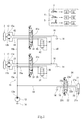
- FIG. 2 is a circuit diagram illustrating a hydraulic circuit according to the embodiment. It is a figure which shows the left and right direction switching valves. It is a circuit diagram showing a conventional example of a hydraulic circuit.
- FIG. 1 is a circuit diagram showing a hydraulic circuit 10 according to the embodiment.
- the hydraulic circuit 10 shown in FIG. 1 is mounted on a construction machine (particularly, a small construction machine).
- the construction machine includes a working device attached to a vehicle body frame, and a required work is performed by operating the working device.
- Excavators and crane trucks can be exemplified as such construction machines.
- the construction machine is self-propelled, and is, for example, a tracked vehicle provided with left and right crawlers.
- the left crawler includes a left starting wheel 1 that rotationally drives the left crawler.
- the right crawler includes a right starting wheel 2 that rotationally drives the right crawler board.
- the construction machine may be a wheeled vehicle having left and right wheels instead of the crawler.
- the operator's seat of the construction machine is provided with left and right traveling operation devices 3 and 4 and one or more working device operation devices 5.
- the type of the travel operation devices 3 and 4 is not particularly limited, and may be a lever or a pedal, or may include both a lever and a pedal.
- the left traveling operation device 3 is used for operating the left crawler
- the right traveling operation device 4 is used for operating the right crawler.
- the left traveling operation device 3 can be operated in two directions, a first operation direction and a second operation direction, from the non-operation neutral position. If the left traveling controller 3 is at the neutral position, the left crawler stops. When the left traveling operation device 3 is operated from the neutral position in the first operation direction, the left crawler rotates in the forward direction (counterclockwise in left side view).
- the left traveling operation device 3 If the left traveling operation device 3 is operated in the second operation direction from the neutral position, the left crawler rotates in the retreating direction (clockwise in left side view). The rotation speed of the left crawler is adjusted according to the operation amount of the left traveling operation device 3. The relationship between the right traveling operation device 4 and the right crawler is the same.
- the hydraulic circuit 10 includes left and right traveling motors 11 and 12 provided as a left traveling motor and a right traveling motor of the construction machine, a pump 13, a tank 14, a working device actuator 21, a working device direction switching valve 22, and a left and right direction switching valve. 31 and 41 and left and right pressure compensating valves 32 and 42 are provided. Note that left and right mean left and right with respect to the forward direction of the construction machine.
- the left running motor 11 has a pair of supply / discharge ports 11a and 11b, and drives the left starting wheel 1 to rotate in the forward or backward direction.
- the right running motor 12 has a pair of supply / discharge ports 12a and 12b, and drives the right starting wheel 2 to rotate in the forward direction or the backward direction.
- the pump 13 sucks in hydraulic oil stored in the tank 14 and discharges pressure oil from a discharge port 13a thereof.
- the pump 13 is a pressure oil supply source for the left and right traveling motors 11 and 12.
- the pressure oil discharged from the pump 13 is supplied to the traveling motors 11 and 12 via the pump line 15 connected to the discharge port 13a.
- the pump 13 may be a pressure oil supply source of the working device actuator 21.
- the second pump line 23 branches off from the pump line 15 and is connected to the pump port 22p of the directional control valve 22 for the working device.
- the tank line 16 is connected to the tank port 22t of the valve 22.
- Reference numeral 22b is connected to supply / discharge ports 21a, 21b of the working device actuator 21 via a pair of supply / discharge lines 24, 25.
- the work device direction switching valve 22 is operated by the work device operating device 5 and controls the supply and discharge of the pressurized oil to and from the work device actuator 21.
- the left direction switching valve 31 corresponds to the left traveling motor 11, the left pressure compensating valve 32, and the left traveling operation device 3.
- the right direction switching valve 41 corresponds to the right traveling motor 12, the right pressure compensating valve 42, and the right traveling operation device 4.
- the left direction switching valve 31 is configured to change the position of the spool according to the operation direction and the operation amount of the left traveling operation device 3.
- the relationship between the right traveling operation device 4 and the spool position of the right direction switching valve 41 is the same.
- leftward switching valve 31 has a pump port 31p, a tank port 31t, a first compensation port 31q, a second compensation port 31r, a pair of supply / discharge ports 31a, 31b, and a communication port 31c.
- the right direction switching valve 41 has a pump port 41p, a tank port 41t, a first compensation port 41q, a second compensation port 41r, a pair of supply / discharge ports 41a and 41b, and a communication port 41c.
- the pump ports 31p and 41p are connected to the discharge port 13a of the pump 13 via the pump line 15.
- the pump line 15 includes a common part 15c of a single system connected to the discharge port 13a, and two branch parts 15a and 15b branched from the common part 15c and connected to the pump ports 31p and 41p, respectively. It is.
- the tank ports 31t and 41t are connected to the tank 14 via the tank line 16.
- the communication port 31c of the left direction switching valve 31 is connected to the communication port 41c of the right direction switching valve 41 via the communication line 50.
- the supply / discharge port 31a is connected to a supply / discharge port 11a of the left traveling motor 11 via a supply / discharge line 33, and the supply / discharge port 31b is connected to the left traveling motor 11 via a supply / discharge line 34.
- the first compensation port 31q is connected to the upstream port 32a of the left pressure compensation valve 32 via the primary compensation line 35.
- the downstream port 32b of the left pressure compensation valve 32 is connected to the second compensation port 31r via the secondary compensation line 36.
- the connection relationship among the compensation ports 41q and 41r, the right pressure compensation valve 42, the supply / discharge ports 41a and 41b, and the right traveling motor 12 is also the same.
- the spool of the leftward switching valve 31 moves from the neutral position in the second movement direction opposite to the first movement direction (see FIGS. 1 and 2). 2 see lower function).
- the pump port 31p communicates with the first compensation port 31q
- the second compensation port 31r communicates with the supply / discharge port 31a and the communication port 31c
- the supply / discharge port 31b communicates with the tank port 31t.
- Reference numerals 41x1 and 41x2 denote variable throttles that indicate that the degree of communication between the pump port 41p and the first compensation port 41q changes according to the amount of movement of the spool when the spool of the rightward switching valve 41 moves from the neutral position. is there.
- Reference numerals 41y1 and 41y2 are variable throttles that indicate that the degree of communication between the second compensation port 41r and the communication port 41c changes according to the amount of movement of the spool when the spool of the rightward switching valve 41 moves from the neutral position. is there.
- the operator When traveling straight ahead, the operator may operate the left and right traveling controllers 3 and 4 in the first operation direction by the same amount. When traveling straight backward, the operator may operate the left and right traveling operation devices 3 and 4 in the second operation direction by the same amount. Usually, when traveling straight, the operator operates the left and right traveling controllers 3 and 4 in full amount. Then, in the left-direction switching valve 31, the spool largely moves from the neutral position in the first or second movement direction, and the degree of communication between the ports 31p and 31q is maximized. The same applies to the right direction switching valve 41. For this reason, it is possible to supply substantially the same amount of large flow to the left and right traveling motors 11 and 12, and it is possible to make the construction machine travel straight at a relatively high speed.
- the downstream side of the left pressure compensating valve 32 communicates with the downstream side of the right pressure compensating valve 42 via the second compensation port 31r, the communication port 31c, the communication line 50, the communication port 41c, and the second compensation port 31r.
- the degree of communication between the second compensation port 31r and the communication port 31c is maximized
- the degree of communication between the second compensation port 41r and the communication port 41c is maximized. Therefore, even if a difference occurs between the load pressures of the left and right traveling motors 11 and 12, the pressure difference can be corrected. Therefore, the load pressures of the traveling motors 11 and 12 and, consequently, the rotation speed are leveled, and the straightness of the construction machine can be maintained.
- the operator operates the left and right traveling operation devices 3 and 4 in the first operation direction.
- the right travel operation device 4 is operated by the full amount
- the left travel operation device 3 is operated by an intermediate amount less than the full amount in accordance with a desired turning radius.
- the communication degree of the rightward switching valve 41 is maximized as in the case of the straight traveling described above.
- the left switching valve 31 since the operation amount is reduced, the movement amount of the spool is also small, and although the ports 31p and 31r are in communication, the communication degree is small. Therefore, the flow rate of supply to the left pressure compensating valve 32 and thus to the second compensation port 31r is also smaller than that of the right side.
- the degree of communication between the second compensation port 31r and the communication port 31c is also reduced. Therefore, although the downstream side of the left pressure compensating valve 32 communicates with the downstream side of the right pressure compensating valve 42 via the communication line 50, the degree of communication is narrower than when traveling straight. Therefore, the difference between the load pressures or the rotational speeds of the left and right traveling motors 11 and 12 is less likely to be cancelled than when traveling straight. Therefore, the construction machine can maintain a state where the rotation speed of the left traveling motor 11 is lower than the rotation speed of the right traveling motor 12. That is, the construction machine can slowly turn leftward while moving forward. The same applies to the gentle rightward turning while moving forward, the gentle leftward turning while moving backward, and the gentle rightward turning while moving backward.
- the worker In turning the left turn, the worker operates the right traveling operation device 4 in the first operation direction by a full amount, while leaving the left traveling operation device 3 unoperated.
- the behavior of the right direction switching valve 41 is the same as in the above-described straight traveling.
- the spool of the left direction switching valve 31 remains at the neutral position. Therefore, the tank port 31t communicates with the supply / discharge ports 31a, 31b, and the other ports 31p, 31q, 31r, 31c are blocked.
- the right running motor 12 rotates while receiving a large flow rate supply, while the left running motor 11 stops. Therefore, the construction machine can pivot on the left front around the stopped left crawler.
- the operator operates the left traveling operation device 3 in the second operation direction by the full amount, while operating the right traveling operation device 4 in the first operation direction by the full amount.
- Both the behavior of the leftward switching valve 31 and the behavior of the rightward switching valve 41 are substantially the same as in the straight traveling described above, except that the spool moves in the second movement direction with the leftward switching valve 31, and the spool moves with the rightward switching valve 41. Moves in the first movement direction.
- the left and right traveling motors 11 and 12 are supplied with a substantially equal large flow rate, but the left and right traveling motors 11 and 12 rotate in opposite directions.
- Communication ports 31c and 41c are provided in the existing direction switching valves 31 and 41, and the degree of communication between the second compensation ports 31r and 41r and the communication ports 31c and 41c is changed according to the amount of movement of the spool. Thus, such an effect is realized. Since the number of valves or the number of oil passages is minimized, the hydraulic circuit 10 can be configured simply.
- communication ports 31c, 41c are provided in the direction switching valves 31, 41, and the degree of communication between the second compensation ports 31r, 41r and the communication ports 31c, 41c is changed according to the amount of movement of the spool.
- a communication line for communicating the second compensation ports 31r, 41r of the left and right direction switching valves 31, 41 when the left and right traveling operation devices 3, 4 are operated is provided, and the left and right communication lines are provided on the communication line.
- a communication degree adjusting device for adjusting the fluid connection between the traveling motors 11 and 12 in accordance with the operation amounts of the traveling operation devices 3 and 4 may be provided.
Landscapes
- Engineering & Computer Science (AREA)
- General Engineering & Computer Science (AREA)
- Mining & Mineral Resources (AREA)
- Civil Engineering (AREA)
- Structural Engineering (AREA)
- Mechanical Engineering (AREA)
- Physics & Mathematics (AREA)
- Fluid Mechanics (AREA)
- Automation & Control Theory (AREA)
- Chemical & Material Sciences (AREA)
- Combustion & Propulsion (AREA)
- Transportation (AREA)
- Operation Control Of Excavators (AREA)
- Fluid-Pressure Circuits (AREA)
- Non-Deflectable Wheels, Steering Of Trailers, Or Other Steering (AREA)
Abstract
左右の方向切換弁の各々が、ポンプと接続されるポンプポート、対応する圧力補償弁の上流側と接続される第1補償ポート、対応する圧力補償弁の下流側と接続される第2補償ポート、対応する走行モータと接続される一対の給排ポート、および連通ポートを有する。左右の方向切換弁の連通ポート同士が連通ラインを介して接続される。走行操作器が操作されてスプールが中立位置から移動すると、ポンプポートが第1補償ポートと連通し、かつ、第2補償ポートが給排ポートの一方および連通ポートと連通する。方向切換弁は、スプールの中立位置からの移動量が大きいほど第2補償ポートと連通ポートとの連通度合が大きくなるよう構成される。
Description
本発明は、建設機械に搭載される油圧回路に関する。
一般に、建設機械の走行駆動源には、左右の油圧モータが用いられる(例えば、特許文献1を参照)。なお、左右とは、建設機械の前進方向に対して左右を意味するものである。図3を参照して、各走行モータ91,92とポンプ93との間には方向切換弁94,95および圧力補償弁96,97が設けられ、運転席には左右の方向切換弁94,95を操作するための左右の走行操作器が設けられる。作業員が走行操作器を操作すると、ポンプ93から吐出された圧油が、方向切換弁94,95および圧力補償弁96,97を介し、走行モータ91,92に供給される。左右の圧力補償弁96,97の下流側同士は、連通ライン98を介して常時連通している。これにより、両方の走行操作器を同方向に操作したときに、両走行モータ91,92の負荷圧あるいは回転速度の平準化が図られ、ひいては、建設機械の直進性能の向上が図られるとしている。
本書では、旋回走行という場合、運転席や作業装置が取り付けられている上部車体フレームの旋回ではなく、走行モータが取り付けられている下部走行フレームによる走行時の直進走行の反義としての旋回走行を指す。建設機械の旋回走行方式として、緩旋回や信地旋回がある。信地旋回は、左右の走行操作器のうち片方の走行操作器のみ操作又は両方の走行操作器を逆操作することで、建設機械全体を旋回走行する方式である。なお、両方の走行操作器を逆方向に全量操作する超信地旋回という方式もある。緩旋回は、両方の走行操作器を同方向に異なる操作量で操作することで、弧を描くように前進または後退して進路を変える方式である。直進走行の場合は、両方の走行操作器を同方向に同量操作すればよい。
特許文献1では、直進のための操作が「同一方向の操作」とされ、緩旋回との区別(操作量異同)を考慮していない。作業員が緩旋回のための操作を行うと、連通ライン98を介して走行モータ91,92のうち低速になるべき方に作動油が流れ込み、建設機械が直進しようとする。直進性能の向上が図られた結果として、旋回走行性能を損ねている。
そこで本発明は、建設機械の直進性能も旋回走行性能も確保することを目的としている。
本発明に係る建設機械の油圧回路は、ポンプと、建設機械の左走行モータおよび右走行モータとして設けられる左右の走行モータと、前記左右の走行モータと対応する左右の圧力補償弁と、前記左右の走行モータと対応する左右の走行操作器と、前記左右の走行モータ、前記左右の圧力補償弁および前記左右の走行操作器と対応し、対応する走行操作器の操作量に応じてスプールの位置を変える左右の方向切換弁と、を備え、前記方向切換弁は、前記ポンプと接続されるポンプポート、対応する圧力補償弁の上流側と接続される第1補償ポート、対応する圧力補償弁の下流側と接続される第2補償ポート、対応する走行モータと接続される一対の給排ポートを有し、前記左右の走行操作器が操作された時に前記左右の方向切換弁の前記第2補償ポート同士を連通させる連通ラインを更に備え、前記左右の走行操作器の操作量に応じて、前記連通ラインの連通度合いが変更されるように構成される。
前記構成によれば、作業員が左右の走行操作器を操作した場合、左右の走行モータ間の流体的な接続状態が走行操作器の操作量に応じて調整されることにより、直進性能の向上のみならず、旋回走行性能(回頭性能)の向上も得られる。
また、本発明に係る建設機械の油圧回路は、ポンプと、建設機械の左走行モータおよび右走行モータとして設けられる左右の走行モータと、前記左右の走行モータと対応する左右の圧力補償弁と、前記左右の走行モータと対応する左右の走行操作器と、前記左右の走行モータ、前記左右の圧力補償弁および前記左右の走行操作器と対応し、対応する走行操作器の操作量に応じてスプールの位置を変える左右の方向切換弁と、を備え、前記方向切換弁は、前記ポンプと接続されるポンプポート、対応する圧力補償弁の上流側と接続される第1補償ポート、対応する圧力補償弁の下流側と接続される第2補償ポート、対応する走行モータと接続される一対の給排ポート、および連通ポートを有し、前記左右の方向切換弁の前記連通ポート同士が連通ラインを介して接続され、前記走行操作器が操作されて前記スプールが中立位置から移動すると、前記ポンプポートが前記第1補償ポートと連通し、かつ、前記第2補償ポートが前記給排ポートの一方および前記連通ポートと連通し、前記方向切換弁は、前記スプールの前記中立位置からの移動量が大きいほど前記第2補償ポートと前記連通ポートとの連通度合が大きくなるよう構成されてもよい。
前記構成によれば、作業員が直進のため左右の走行操作器を同量操作した場合、ポンプからの圧油が、ポンプポート、第1補償ポート、圧力補償弁、第2補償ポートおよび給排ポートの一方を介し、左右の走行モータに供給される。また、第2補償ポートが連通ポートと連通する。そのため、左右の走行モータの負荷圧に差が生じても、左右の圧力補償弁の下流側同士が連通ラインを介して連通し、その差が補正される。よって、建設機械の直進操作時においては、左右の走行モータの負荷圧に差が生じても、負荷圧の差を十分に補正できるため、直進性能が十分に得られる。
また、作業員が旋回走行のため左右の走行操作器を異なる操作量で操作した場合にも、直進時と同様、左右の圧力補償弁の下流側同士が連通ラインを介して連通する。ただし、操作量が小さい側の方向切換弁では、スプールの移動量が小さく、第2補償ポートと連通ポートとの連通度合が比較的に小さくなる。そのため、負荷圧の差は直進時と比べて補正されにくい。よって、建設機械の旋回走行操作時においては、左右の走行モータの負荷圧に差が生じても、負荷圧の差を補正しないようにすることができるため、旋回走行性能も十分に得られる。
また、本発明に係る建設機械の油圧回路において、前記走行操作器が非操作で前記スプールが前記中立位置にあれば、前記連通ポートがブロックされるように構成されてもよい。
前記構成によれば、作業員が信地旋回のため片方の走行操作器のみ操作している場合、非操作側の方向切換弁において連通ポートがブロックされる。圧力補償弁の下流側同士が常時連通することを回避でき、作動油は操作側から非操作側に流れない。よって、無効流量の発生を抑止できる。
本発明によれば、建設機械の直進性能も旋回走行性能も確保できる。
図1は、実施形態に係る油圧回路10を示す回路図である。図1に示す油圧回路10は、建設機械(特に、小型の建設機械)に搭載される。詳細図示を省略するが、建設機械は、車体フレームに取り付けられた作業装置を備え、作業装置を動作させて所要の作業が行われる。このような建設機械として、ショベルカー、クレーン車を例示できる。建設機械は自走可能であり、一例として、左右のクローラを備えた装軌車両である。左クローラは、左履板を回転駆動する左起動輪1を備える。右クローラは、右履板を回転駆動する右起動輪2を備える。ただし、建設機械は、クローラに代えて左右の車輪を備えた装輪車両でもよい。
建設機械の運転席には、左右の走行操作器3,4と、1以上の作業装置操作器5とが設けられる。走行操作器3,4の形式は特に限定されず、レバーでもペダルでもよく、また、レバーおよびペダルを両方備えてもよい。左走行操作器3は左クローラの操作に用いられ、右走行操作器4は右クローラの操作に用いられる。左走行操作器3は、非操作の中立位置から第1操作方向および第2操作方向の2方向に操作できる。左走行操作器3が中立位置にあれば、左クローラは停止する。左走行操作器3が中立位置から第1操作方向に操作されれば、左クローラが前進方向(左側面視で反時計回り)に回転する。左走行操作器3が中立位置から第2操作方向に操作されれば、左クローラが後退方向(左側面視で時計回り)に回転する。左クローラの回転速度は、左走行操作器3の操作量に応じて調整される。右走行操作器4と右クローラとの関係も、これと同様である。
油圧回路10は、建設機械の左走行モータおよび右走行モータとして設けられる左右の走行モータ11,12、ポンプ13、タンク14、作業装置アクチュエータ21、作業装置用方向切換弁22、左右の方向切換弁31,41、および、左右の圧力補償弁32,42を備えている。なお、左右とは、建設機械の前進方向に対して左右を意味するものである。
左走行モータ11は、一対の給排ポート11a,11bを有し、左起動輪1を前進方向または後退方向に回転駆動する。右走行モータ12は、一対の給排ポート12a,12bを有し、右起動輪2を前進方向または後退方向に回転駆動する。ポンプ13は、タンク14に溜められている作動油を吸い込み、その吐出口13aより圧油を吐出する。ポンプ13は、左右の走行モータ11,12の圧油供給源である。ポンプ13から吐出された圧油は、吐出口13aに接続されたポンプライン15を介し、走行モータ11,12に供給される。
一例として、ポンプ13は、作業装置アクチュエータ21の圧油供給源であってもよい。第2ポンプライン23がポンプライン15から分岐して作業装置用方向切換弁22のポンプポート22pに接続され、タンクライン16が当該弁22のタンクポート22tに接続され、一対の給排ポート22a,22bが一対の給排ライン24,25を介して作業装置アクチュエータ21の給排ポート21a,21bに接続されている。作業装置用方向切換弁22は、作業装置操作器5によって操作され、作業装置アクチュエータ21に対する圧油給排を制御する。
左方向切換弁31は、左走行モータ11、左圧力補償弁32および左走行操作器3と対応している。右方向切換弁41は、右走行モータ12、右圧力補償弁42および右走行操作器4と対応している。左方向切換弁31は、左走行操作器3の操作方向および操作量に応じてスプールの位置を変えるように構成されている。右走行操作器4と右方向切換弁41のスプール位置との関係も、これと同様である。
図2を参照して、左方向切換弁31は、ポンプポート31p、タンクポート31t、第1補償ポート31q、第2補償ポート31r、一対の給排ポート31a,31bおよび連通ポート31cを有している。右方向切換弁41も同様に、ポンプポート41p、タンクポート41t、第1補償ポート41q、第2補償ポート41r、一対の給排ポート41a,41bおよび連通ポート41cを有している。
ポンプポート31p,41pは、ポンプライン15を介してポンプ13の吐出口13aと接続されている。ポンプライン15には、吐出口13aに接続された単一系統の共通部15cと、共通部15cから分岐してポンプポート31p,41pそれぞれに接続される2本の分岐部15a,15bとが含まれる。タンクポート31t,41tは、タンクライン16を介してタンク14と接続されている。左方向切換弁31の連通ポート31cは、連通ライン50を介し、右方向切換弁41の連通ポート41cに接続されている。
左方向切換弁31に関し、給排ポート31aは、給排ライン33を介して左走行モータ11の給排ポート11aに接続され、給排ポート31bは、給排ライン34を介して左走行モータ11の給排ポート11bに接続されている。第1補償ポート31qは、一次補償ライン35を介して、左圧力補償弁32の上流ポート32aと接続されている。左圧力補償弁32の下流ポート32bは、二次補償ライン36を介して第2補償ポート31rと接続されている。補償ポート41q,41r、右圧力補償弁42、給排ポート41a,41bおよび右走行モータ12の間の接続関係も、これと同様である。
左走行操作器3が非操作で中立位置にあるとき、左方向切換弁31のスプールは中立位置に位置づけられる(図1および図2の中央ファンクションを参照)。このとき、ポンプポート31p、第1補償ポート31q、第2補償ポート31rおよび連通ポート31cがブロックされる。給排ポート31a,31bはタンクポート31tと連通する。
左走行操作器3が中立位置から第1操作方向に操作されると、左方向切換弁31のスプールは中立位置から第1移動方向に移動する(図1および図2の上ファンクションを参照)。このとき、ポンプポート31pが第1補償ポート31qと連通し、第2補償ポート31rが給排ポート31bおよび連通ポート31cと連通し、給排ポート31aがタンクポート31tと連通する。
左走行操作器3が中立位置から第2操作方向に操作されると、左方向切換弁31のスプールは中立位置から第1移動方向とは反対の第2移動方向に移動する(図1および図2の下ファンクションを参照)。このとき、ポンプポート31pが第1補償ポート31qと連通し、第2補償ポート31rが給排ポート31aおよび連通ポート31cと連通し、給排ポート31bがタンクポート31tと連通する。
左方向切換弁31のスプールが中立位置から移動すると、その移動方向に関わらず、ポンプポート31pが第1補償ポート31qと連通する。左走行操作器3の操作量が大きくスプールの中立位置からの移動量が大きいほど、これらポート31p,31qの連通度合も大きくなる。この点、図2では、左方向切換弁31の上下ファンクションにて、ポート31p,31qが連通する旨示す矢印記号に、可変絞り31x1,31x2を表す記号を付している。
左方向切換弁31のスプールが中立位置から移動すると、その移動方向に関わらず、第2補償ポート31rが連通ポート31cと連通する。左走行操作器3の操作量が大きくスプールの中立位置からの移動量が大きいほど、これらポート31r,31cの連通度合も大きくなる。この点、図2では、左方向切換弁31の上下ファンクションにて、ポート31r,31cが連通する旨示す矢印記号に、可変絞り31y1,31y2を表す記号を付している。
右方向切換弁41のスプール位置とポート連通状態との関係も、上記同様である。参照符号41x1,41x2は、右方向切換弁41のスプールが中立位置から移動したときに、スプールの移動量に応じてポンプポート41pと第1補償ポート41qとの連通度合が変わる旨示す可変絞りである。参照符号41y1,41y2は、右方向切換弁41のスプールが中立位置から移動したときに、スプールの移動量に応じて第2補償ポート41rと連通ポート41cとの連通度合が変わる旨示す可変絞りである。
上記構成の油圧回路10の作用について説明する。
前方直進に際し、作業員は、左右の走行操作器3,4を第1操作方向に同量操作すればよい。後方直進に際し、作業員は、左右の走行操作器3,4を第2操作方向に同量操作すればよい。通例、直進に際し、作業員は、左右の走行操作器3,4を全量操作する。すると、左方向切換弁31では、スプールが中立位置から第1または第2移動方向に大きく移動し、ポート31p,31qの連通度合が最大化される。右方向切換弁41でもこれと同様である。このため、左右の走行モータ11,12に概略等量の大流量を供給でき、比較的に高速で建設機械を直進走行させることができる。
更に、左圧力補償弁32の下流側が、第2補償ポート31r、連通ポート31c、連通ライン50、連通ポート41cおよび第2補償ポート31rを介し、右圧力補償弁42の下流側と連通する。左方向切換弁31では第2補償ポート31rと連通ポート31cとの連通度合は最大化され、右方向切換弁41でも第2補償ポート41rと連通ポート41cとの連通度合は最大化される。そのため、仮に左右の走行モータ11,12の負荷圧に差が生じようとしても、その圧力差を補正できる。よって、走行モータ11,12の負荷圧ひいては回転速度が平準化され、建設機械の直進性を保つことができる。
前進中の左方緩旋回に際し、作業員は、左右の走行操作器3,4を第1操作方向に操作する。右走行操作器4は全量操作され、左走行操作器3は、所望の旋回走行半径に応じて全量に満たない中間量だけ操作される。この場合、右方向切換弁41では、上記した直進時と同様に連通度合が最大化される。左方向切換弁31では、操作量が減じられているのでスプールの移動量も小さくなり、ポート31p,31rは連通するものの、その連通度合が小さくなる。そのため、左圧力補償弁32ひいては第2補償ポート31rへの供給流量も、右側と比べて小さくなる。
左方向切換弁31では、第2補償ポート31rと連通ポート31cとの連通度合も小さくなる。そのため、左圧力補償弁32の下流側は、右圧力補償弁42の下流側と連通ライン50を介して連通するものの、直進時と比べれば連通度は絞られている。よって、左右の走行モータ11,12の負荷圧あるいは回転速度の差が、直進時と比べれば相殺されにくい。そのため、建設機械は、左走行モータ11の回転速度が右走行モータ12の回転速度よりも低い状態を維持できる。すなわち、建設機械は、前進しながら左方へ緩旋回できる。前進中の右方緩旋回、後進中の左方緩旋回および後進中の右方緩旋回も、これと同様である。
左前回りの信地旋回に際し、作業員は、右走行操作器4を第1操作方向に全量操作する一方で、左走行操作器3を非操作とする。右方向切換弁41の挙動は上記した直進時と同様である。左方向切換弁31のスプールは中立位置に留まる。そのため、タンクポート31tは給排ポート31a,31bと連通し、その他のポート31p,31q,31r,31cはブロックされる。右走行モータ12は大流量の供給を受けて回転する一方で、左走行モータ11は停止する。そのため、建設機械は、停止している左クローラを軸として左前回りに信地旋回できる。連通ポート31cがブロックされているので、回転側である右圧力補償弁42の下流側は、停止側である左圧力補償弁32の下流側から遮断される。右圧力補償弁42を通過した作動油は、左方向切換弁31を通過できない。そのため、無効流量の発生を抑止できる。右前回り、左後回りおよび右後回りの信地旋回も、これと同様である。
左前回りの超信地旋回に際し、作業員は、左走行操作器3を第2操作方向に全量操作する一方で、右走行操作器4を第1操作方向に全量操作する。左方向切換弁31の挙動も右方向切換弁41の挙動も概ね上記した直進時と同じであるが、左方向切換弁31ではスプールが第2移動方向に移動し、右方向切換弁41ではスプールが第1移動方向に移動する。左右の走行モータ11,12には概略等量の大流量が供給されるが、左右の走行モータ11,12は互いに逆方向に回転する。仮に左右の走行モータ11,12の負荷圧に差が生じようとしても、その圧力差を補正でき、走行モータ11,12の負荷圧ひいては回転速度が平準化される。そのため、建設機械は、その場から大きく移動することなく超信地旋回できる。右前回り、左後回りおよび右後回りの超信地旋回も、これと同様である。
上記したとおり、本実施形態によれば、直進性能も旋回走行性能も確保できる。従前存在する方向切換弁31,41に連通ポート31c,41cを設け、第2補償ポート31r,41rと連通ポート31c,41cとの連通度合をスプールの移動量に応じて変えるという構成を採用することで、このような作用を実現している。弁数あるいは油路数が極力抑えられており、油圧回路10を簡素に構成できる。
これまで本発明の実施形態について説明したが、上記構成は本発明の範囲内で適宜変更可能である。 例えば、上記実施形態の「方向切換弁31,41に連通ポート31c,41cを設け、第2補償ポート31r,41rと連通ポート31c,41cとの連通度合をスプールの移動量に応じて変える」という構成に代えて、左右の走行操作器3,4が操作された時に左右の方向切換弁31,41の第2補償ポート31r,41r同士を連通させる連通ラインを設け、その連通ライン上に左右の走行モータ11,12間の流体的な接続を走行操作器3,4の操作量に応じて調整する連通度合調整装置を設けるように構成してもよい。
3,4 走行操作器
10 油圧回路
11,12 走行モータ
13 ポンプ
31,41 方向切換弁
31p,41p ポンプポート
31q,41q 第1補償ポート
31r,41r 第2補償ポート
31a,31b,41a,41b 給排ポート
31c,41c 連通ポート
32,42 圧力補償弁
50 連通ライン
10 油圧回路
11,12 走行モータ
13 ポンプ
31,41 方向切換弁
31p,41p ポンプポート
31q,41q 第1補償ポート
31r,41r 第2補償ポート
31a,31b,41a,41b 給排ポート
31c,41c 連通ポート
32,42 圧力補償弁
50 連通ライン
Claims (3)
- ポンプと、
建設機械の左走行モータおよび右走行モータとして設けられる左右の走行モータと、
前記左右の走行モータと対応する左右の圧力補償弁と、
前記左右の走行モータと対応する左右の走行操作器と、
前記左右の走行モータ、前記左右の圧力補償弁および前記左右の走行操作器と対応し、対応する走行操作器の操作量に応じてスプールの位置を変える左右の方向切換弁と、を備え、
前記方向切換弁は、前記ポンプと接続されるポンプポート、対応する圧力補償弁の上流側と接続される第1補償ポート、対応する圧力補償弁の下流側と接続される第2補償ポート、対応する走行モータと接続される一対の給排ポートを有し、
前記左右の走行操作器が操作された時に前記左右の方向切換弁の前記第2補償ポート同士を連通させる連通ラインを更に備え、
前記左右の走行操作器の操作量に応じて、前記連通ラインの連通度合いが変更される、建設機械の油圧回路。 - ポンプと、
建設機械の左走行モータおよび右走行モータとして設けられる左右の走行モータと、
前記左右の走行モータと対応する左右の圧力補償弁と、
前記左右の走行モータと対応する左右の走行操作器と、
前記左右の走行モータ、前記左右の圧力補償弁および前記左右の走行操作器と対応し、対応する走行操作器の操作量に応じてスプールの位置を変える左右の方向切換弁と、を備え、
前記方向切換弁は、前記ポンプと接続されるポンプポート、対応する圧力補償弁の上流側と接続される第1補償ポート、対応する圧力補償弁の下流側と接続される第2補償ポート、対応する走行モータと接続される一対の給排ポート、および連通ポートを有し、
前記左右の方向切換弁の前記連通ポート同士が連通ラインを介して接続され、
前記走行操作器が操作されて前記スプールが中立位置から移動すると、前記ポンプポートが前記第1補償ポートと連通し、かつ、前記第2補償ポートが前記給排ポートの一方および前記連通ポートと連通し、
前記方向切換弁は、前記スプールの前記中立位置からの移動量が大きいほど前記第2補償ポートと前記連通ポートとの連通度合が大きくなるよう構成される、建設機械の油圧回路。 - 前記走行操作器が非操作で前記スプールが前記中立位置にあれば、前記連通ポートがブロックされる、請求項1または2に記載の建設機械の油圧回路。
Priority Applications (3)
| Application Number | Priority Date | Filing Date | Title |
|---|---|---|---|
| US17/262,780 US11242671B2 (en) | 2018-08-10 | 2019-08-01 | Hydraulic circuit of construction machine |
| CN201980048931.XA CN112424486B (zh) | 2018-08-10 | 2019-08-01 | 工程机械的油压回路 |
| DE112019004016.2T DE112019004016T8 (de) | 2018-08-10 | 2019-08-01 | Hydraulikkreislauf einer baumaschine |
Applications Claiming Priority (2)
| Application Number | Priority Date | Filing Date | Title |
|---|---|---|---|
| JP2018151070A JP7049213B2 (ja) | 2018-08-10 | 2018-08-10 | 建設機械の油圧回路 |
| JP2018-151070 | 2018-08-10 |
Publications (1)
| Publication Number | Publication Date |
|---|---|
| WO2020031817A1 true WO2020031817A1 (ja) | 2020-02-13 |
Family
ID=69414208
Family Applications (1)
| Application Number | Title | Priority Date | Filing Date |
|---|---|---|---|
| PCT/JP2019/030114 Ceased WO2020031817A1 (ja) | 2018-08-10 | 2019-08-01 | 建設機械の油圧回路 |
Country Status (5)
| Country | Link |
|---|---|
| US (1) | US11242671B2 (ja) |
| JP (1) | JP7049213B2 (ja) |
| CN (1) | CN112424486B (ja) |
| DE (1) | DE112019004016T8 (ja) |
| WO (1) | WO2020031817A1 (ja) |
Families Citing this family (3)
| Publication number | Priority date | Publication date | Assignee | Title |
|---|---|---|---|---|
| JP7461754B2 (ja) | 2020-02-20 | 2024-04-04 | 株式会社ダイセル | ポリイソシアネート化合物、並びに、それを用いたポリウレタン樹脂形成用組成物、及びその硬化物 |
| DE102021208118B4 (de) * | 2021-07-28 | 2026-04-30 | Robert Bosch Gesellschaft mit beschränkter Haftung | Hydrostatischer Fahrantrieb für ein seitengelenktes Fahrzeug und hydrostatischer Antrieb für eine seitengelenkte mobile Arbeitsmaschine |
| AT18551U1 (de) * | 2024-05-29 | 2025-10-15 | Palfinger Ag | Fahrantrieb |
Citations (3)
| Publication number | Priority date | Publication date | Assignee | Title |
|---|---|---|---|---|
| JPH04261923A (ja) * | 1991-01-10 | 1992-09-17 | Kayaba Ind Co Ltd | 建設車両の直進走行制御装置 |
| KR20050066038A (ko) * | 2003-12-26 | 2005-06-30 | 두산인프라코어 주식회사 | 굴삭기의 주행 및 프론트작업의 복합동작용 유압제어장치 |
| JP2015064024A (ja) * | 2013-09-24 | 2015-04-09 | 株式会社神戸製鋼所 | 作業用機械の油圧走行装置 |
Family Cites Families (15)
| Publication number | Priority date | Publication date | Assignee | Title |
|---|---|---|---|---|
| IN171213B (ja) * | 1988-01-27 | 1992-08-15 | Hitachi Construction Machinery | |
| JPH04210101A (ja) * | 1990-11-30 | 1992-07-31 | Komatsu Ltd | 油圧回路 |
| JPH04224470A (ja) | 1990-12-26 | 1992-08-13 | Kayaba Ind Co Ltd | 建設車両の直進走行制御装置 |
| JP3124094B2 (ja) * | 1991-12-25 | 2001-01-15 | カヤバ工業株式会社 | 複数アクチュエータの制御装置 |
| JPH082269A (ja) * | 1994-06-21 | 1996-01-09 | Komatsu Ltd | 油圧駆動式走行装置の走行制御回路 |
| US5950429A (en) * | 1997-12-17 | 1999-09-14 | Husco International, Inc. | Hydraulic control valve system with load sensing priority |
| US6318079B1 (en) * | 2000-08-08 | 2001-11-20 | Husco International, Inc. | Hydraulic control valve system with pressure compensated flow control |
| US6895852B2 (en) * | 2003-05-02 | 2005-05-24 | Husco International, Inc. | Apparatus and method for providing reduced hydraulic flow to a plurality of actuatable devices in a pressure compensated hydraulic system |
| JP2005096704A (ja) * | 2003-09-26 | 2005-04-14 | Hitachi Constr Mach Co Ltd | 走行式建設機械の油圧駆動装置 |
| JP2006336731A (ja) * | 2005-06-01 | 2006-12-14 | Shin Caterpillar Mitsubishi Ltd | 作業機械における走行用油圧制御装置 |
| US7487707B2 (en) * | 2006-09-27 | 2009-02-10 | Husco International, Inc. | Hydraulic valve assembly with a pressure compensated directional spool valve and a regeneration shunt valve |
| DE102006060334B4 (de) * | 2006-12-20 | 2011-08-25 | Sauer-Danfoss Aps | Hydraulische Ventilanordnung |
| DE102010009704A1 (de) * | 2010-03-01 | 2011-09-01 | Robert Bosch Gmbh | Hydraulischer Fahrantrieb und Verfahren zum Steuern eines derartigen Fahrantriebs |
| JP5528276B2 (ja) * | 2010-09-21 | 2014-06-25 | 株式会社クボタ | 作業機の油圧システム |
| JP6603560B2 (ja) * | 2015-12-04 | 2019-11-06 | 川崎重工業株式会社 | 圧力補償ユニット |
-
2018
- 2018-08-10 JP JP2018151070A patent/JP7049213B2/ja active Active
-
2019
- 2019-08-01 WO PCT/JP2019/030114 patent/WO2020031817A1/ja not_active Ceased
- 2019-08-01 DE DE112019004016.2T patent/DE112019004016T8/de active Active
- 2019-08-01 CN CN201980048931.XA patent/CN112424486B/zh active Active
- 2019-08-01 US US17/262,780 patent/US11242671B2/en active Active
Patent Citations (3)
| Publication number | Priority date | Publication date | Assignee | Title |
|---|---|---|---|---|
| JPH04261923A (ja) * | 1991-01-10 | 1992-09-17 | Kayaba Ind Co Ltd | 建設車両の直進走行制御装置 |
| KR20050066038A (ko) * | 2003-12-26 | 2005-06-30 | 두산인프라코어 주식회사 | 굴삭기의 주행 및 프론트작업의 복합동작용 유압제어장치 |
| JP2015064024A (ja) * | 2013-09-24 | 2015-04-09 | 株式会社神戸製鋼所 | 作業用機械の油圧走行装置 |
Also Published As
| Publication number | Publication date |
|---|---|
| DE112019004016T5 (de) | 2021-04-29 |
| CN112424486B (zh) | 2022-12-02 |
| US20210270015A1 (en) | 2021-09-02 |
| JP2020026827A (ja) | 2020-02-20 |
| DE112019004016T8 (de) | 2021-07-08 |
| US11242671B2 (en) | 2022-02-08 |
| JP7049213B2 (ja) | 2022-04-06 |
| CN112424486A (zh) | 2021-02-26 |
Similar Documents
| Publication | Publication Date | Title |
|---|---|---|
| JP5367893B2 (ja) | ホイールローダのステアリング装置 | |
| JP4825765B2 (ja) | バックホーの油圧システム | |
| WO2016208530A1 (ja) | 建設・輸送・農業機械のステアリング装置 | |
| JP2017141892A (ja) | 車両 | |
| JP2020026827A (ja) | 建設機械の油圧回路 | |
| JP6964052B2 (ja) | 建設機械の油圧回路 | |
| JP5293176B2 (ja) | 建設機械の油圧制御装置 | |
| JPH0232167B2 (ja) | ||
| WO2015115428A1 (ja) | 作業機の制御システム及び低圧選択回路 | |
| JP2019183972A (ja) | 作業車両の油圧回路 | |
| WO2014073551A9 (ja) | パワーショベルの流体圧制御装置 | |
| EP2792575B1 (en) | Steering system for wheeled construction equipment | |
| JP2005096704A (ja) | 走行式建設機械の油圧駆動装置 | |
| JP2624268B2 (ja) | 建設機械の油圧駆動装置 | |
| JPH0674054B2 (ja) | 油圧走行車両に於ける直進走行制御回路装置 | |
| CN119435490A (zh) | 液压驱动装置 | |
| JPH0640055Y2 (ja) | 油圧走行車両に於ける直進走行制御回路装置 | |
| JP2006077846A (ja) | ホイール式建設機械 | |
| JP2012207688A (ja) | 油圧式建設機械の緊急油圧駆動装置 | |
| JPH11303148A (ja) | 建設機械の油圧回路 | |
| JP2017048868A (ja) | 作業機械の駆動装置 | |
| JP2005247149A (ja) | 作業車両用ステアリング装置 |
Legal Events
| Date | Code | Title | Description |
|---|---|---|---|
| 121 | Ep: the epo has been informed by wipo that ep was designated in this application |
Ref document number: 19847213 Country of ref document: EP Kind code of ref document: A1 |
|
| 122 | Ep: pct application non-entry in european phase |
Ref document number: 19847213 Country of ref document: EP Kind code of ref document: A1 |