WO2020031816A1 - 建設機械の油圧回路 - Google Patents
建設機械の油圧回路 Download PDFInfo
- Publication number
- WO2020031816A1 WO2020031816A1 PCT/JP2019/030113 JP2019030113W WO2020031816A1 WO 2020031816 A1 WO2020031816 A1 WO 2020031816A1 JP 2019030113 W JP2019030113 W JP 2019030113W WO 2020031816 A1 WO2020031816 A1 WO 2020031816A1
- Authority
- WO
- WIPO (PCT)
- Prior art keywords
- pump
- actuator
- port
- pressure
- valve
- Prior art date
- Legal status (The legal status is an assumption and is not a legal conclusion. Google has not performed a legal analysis and makes no representation as to the accuracy of the status listed.)
- Ceased
Links
Images

Classifications
-
- F—MECHANICAL ENGINEERING; LIGHTING; HEATING; WEAPONS; BLASTING
- F15—FLUID-PRESSURE ACTUATORS; HYDRAULICS OR PNEUMATICS IN GENERAL
- F15B—SYSTEMS ACTING BY MEANS OF FLUIDS IN GENERAL; FLUID-PRESSURE ACTUATORS, e.g. SERVOMOTORS; DETAILS OF FLUID-PRESSURE SYSTEMS, NOT OTHERWISE PROVIDED FOR
- F15B11/00—Servomotor systems without provision for follow-up action; Circuits therefor
- F15B11/16—Servomotor systems without provision for follow-up action; Circuits therefor with two or more servomotors
- F15B11/161—Servomotor systems without provision for follow-up action; Circuits therefor with two or more servomotors with sensing of servomotor demand or load
- F15B11/162—Servomotor systems without provision for follow-up action; Circuits therefor with two or more servomotors with sensing of servomotor demand or load for giving priority to particular servomotors or users
-
- E—FIXED CONSTRUCTIONS
- E02—HYDRAULIC ENGINEERING; FOUNDATIONS; SOIL SHIFTING
- E02F—DREDGING; SOIL-SHIFTING
- E02F9/00—Component parts of dredgers or soil-shifting machines, not restricted to one of the kinds covered by groups E02F3/00 - E02F7/00
- E02F9/20—Drives; Control devices
- E02F9/22—Hydraulic or pneumatic drives
- E02F9/2278—Hydraulic circuits
-
- E—FIXED CONSTRUCTIONS
- E02—HYDRAULIC ENGINEERING; FOUNDATIONS; SOIL SHIFTING
- E02F—DREDGING; SOIL-SHIFTING
- E02F9/00—Component parts of dredgers or soil-shifting machines, not restricted to one of the kinds covered by groups E02F3/00 - E02F7/00
- E02F9/20—Drives; Control devices
- E02F9/22—Hydraulic or pneumatic drives
- E02F9/2221—Control of flow rate; Load sensing arrangements
- E02F9/2225—Control of flow rate; Load sensing arrangements using pressure-compensating valves
- E02F9/2228—Control of flow rate; Load sensing arrangements using pressure-compensating valves including an electronic controller
-
- E—FIXED CONSTRUCTIONS
- E02—HYDRAULIC ENGINEERING; FOUNDATIONS; SOIL SHIFTING
- E02F—DREDGING; SOIL-SHIFTING
- E02F9/00—Component parts of dredgers or soil-shifting machines, not restricted to one of the kinds covered by groups E02F3/00 - E02F7/00
- E02F9/20—Drives; Control devices
- E02F9/22—Hydraulic or pneumatic drives
- E02F9/225—Control of steering, e.g. for hydraulic motors driving the vehicle tracks
-
- E—FIXED CONSTRUCTIONS
- E02—HYDRAULIC ENGINEERING; FOUNDATIONS; SOIL SHIFTING
- E02F—DREDGING; SOIL-SHIFTING
- E02F9/00—Component parts of dredgers or soil-shifting machines, not restricted to one of the kinds covered by groups E02F3/00 - E02F7/00
- E02F9/20—Drives; Control devices
- E02F9/22—Hydraulic or pneumatic drives
- E02F9/2264—Arrangements or adaptations of elements for hydraulic drives
- E02F9/2267—Valves or distributors
-
- E—FIXED CONSTRUCTIONS
- E02—HYDRAULIC ENGINEERING; FOUNDATIONS; SOIL SHIFTING
- E02F—DREDGING; SOIL-SHIFTING
- E02F9/00—Component parts of dredgers or soil-shifting machines, not restricted to one of the kinds covered by groups E02F3/00 - E02F7/00
- E02F9/20—Drives; Control devices
- E02F9/22—Hydraulic or pneumatic drives
- E02F9/2221—Control of flow rate; Load sensing arrangements
- E02F9/2225—Control of flow rate; Load sensing arrangements using pressure-compensating valves
-
- F—MECHANICAL ENGINEERING; LIGHTING; HEATING; WEAPONS; BLASTING
- F15—FLUID-PRESSURE ACTUATORS; HYDRAULICS OR PNEUMATICS IN GENERAL
- F15B—SYSTEMS ACTING BY MEANS OF FLUIDS IN GENERAL; FLUID-PRESSURE ACTUATORS, e.g. SERVOMOTORS; DETAILS OF FLUID-PRESSURE SYSTEMS, NOT OTHERWISE PROVIDED FOR
- F15B11/00—Servomotor systems without provision for follow-up action; Circuits therefor
- F15B11/16—Servomotor systems without provision for follow-up action; Circuits therefor with two or more servomotors
-
- F—MECHANICAL ENGINEERING; LIGHTING; HEATING; WEAPONS; BLASTING
- F15—FLUID-PRESSURE ACTUATORS; HYDRAULICS OR PNEUMATICS IN GENERAL
- F15B—SYSTEMS ACTING BY MEANS OF FLUIDS IN GENERAL; FLUID-PRESSURE ACTUATORS, e.g. SERVOMOTORS; DETAILS OF FLUID-PRESSURE SYSTEMS, NOT OTHERWISE PROVIDED FOR
- F15B2211/00—Circuits for servomotor systems
- F15B2211/30—Directional control
- F15B2211/305—Directional control characterised by the type of valves
- F15B2211/30525—Directional control valves, e.g. 4/3-directional control valve
- F15B2211/3053—In combination with a pressure compensating valve
- F15B2211/30535—In combination with a pressure compensating valve the pressure compensating valve is arranged between pressure source and directional control valve
-
- F—MECHANICAL ENGINEERING; LIGHTING; HEATING; WEAPONS; BLASTING
- F15—FLUID-PRESSURE ACTUATORS; HYDRAULICS OR PNEUMATICS IN GENERAL
- F15B—SYSTEMS ACTING BY MEANS OF FLUIDS IN GENERAL; FLUID-PRESSURE ACTUATORS, e.g. SERVOMOTORS; DETAILS OF FLUID-PRESSURE SYSTEMS, NOT OTHERWISE PROVIDED FOR
- F15B2211/00—Circuits for servomotor systems
- F15B2211/30—Directional control
- F15B2211/305—Directional control characterised by the type of valves
- F15B2211/30525—Directional control valves, e.g. 4/3-directional control valve
- F15B2211/3053—In combination with a pressure compensating valve
- F15B2211/30555—Inlet and outlet of the pressure compensating valve being connected to the directional control valve
-
- F—MECHANICAL ENGINEERING; LIGHTING; HEATING; WEAPONS; BLASTING
- F15—FLUID-PRESSURE ACTUATORS; HYDRAULICS OR PNEUMATICS IN GENERAL
- F15B—SYSTEMS ACTING BY MEANS OF FLUIDS IN GENERAL; FLUID-PRESSURE ACTUATORS, e.g. SERVOMOTORS; DETAILS OF FLUID-PRESSURE SYSTEMS, NOT OTHERWISE PROVIDED FOR
- F15B2211/00—Circuits for servomotor systems
- F15B2211/60—Circuit components or control therefor
- F15B2211/63—Electronic controllers
- F15B2211/6303—Electronic controllers using input signals
- F15B2211/6306—Electronic controllers using input signals representing a pressure
- F15B2211/6313—Electronic controllers using input signals representing a pressure the pressure being a load pressure
-
- F—MECHANICAL ENGINEERING; LIGHTING; HEATING; WEAPONS; BLASTING
- F15—FLUID-PRESSURE ACTUATORS; HYDRAULICS OR PNEUMATICS IN GENERAL
- F15B—SYSTEMS ACTING BY MEANS OF FLUIDS IN GENERAL; FLUID-PRESSURE ACTUATORS, e.g. SERVOMOTORS; DETAILS OF FLUID-PRESSURE SYSTEMS, NOT OTHERWISE PROVIDED FOR
- F15B2211/00—Circuits for servomotor systems
- F15B2211/70—Output members, e.g. hydraulic motors or cylinders or control therefor
- F15B2211/705—Output members, e.g. hydraulic motors or cylinders or control therefor characterised by the type of output members or actuators
- F15B2211/7051—Linear output members
- F15B2211/7053—Double-acting output members
-
- F—MECHANICAL ENGINEERING; LIGHTING; HEATING; WEAPONS; BLASTING
- F15—FLUID-PRESSURE ACTUATORS; HYDRAULICS OR PNEUMATICS IN GENERAL
- F15B—SYSTEMS ACTING BY MEANS OF FLUIDS IN GENERAL; FLUID-PRESSURE ACTUATORS, e.g. SERVOMOTORS; DETAILS OF FLUID-PRESSURE SYSTEMS, NOT OTHERWISE PROVIDED FOR
- F15B2211/00—Circuits for servomotor systems
- F15B2211/70—Output members, e.g. hydraulic motors or cylinders or control therefor
- F15B2211/705—Output members, e.g. hydraulic motors or cylinders or control therefor characterised by the type of output members or actuators
- F15B2211/7058—Rotary output members
-
- F—MECHANICAL ENGINEERING; LIGHTING; HEATING; WEAPONS; BLASTING
- F15—FLUID-PRESSURE ACTUATORS; HYDRAULICS OR PNEUMATICS IN GENERAL
- F15B—SYSTEMS ACTING BY MEANS OF FLUIDS IN GENERAL; FLUID-PRESSURE ACTUATORS, e.g. SERVOMOTORS; DETAILS OF FLUID-PRESSURE SYSTEMS, NOT OTHERWISE PROVIDED FOR
- F15B2211/00—Circuits for servomotor systems
- F15B2211/70—Output members, e.g. hydraulic motors or cylinders or control therefor
- F15B2211/71—Multiple output members, e.g. multiple hydraulic motors or cylinders
- F15B2211/7135—Combinations of output members of different types, e.g. single-acting cylinders with rotary motors
-
- F—MECHANICAL ENGINEERING; LIGHTING; HEATING; WEAPONS; BLASTING
- F15—FLUID-PRESSURE ACTUATORS; HYDRAULICS OR PNEUMATICS IN GENERAL
- F15B—SYSTEMS ACTING BY MEANS OF FLUIDS IN GENERAL; FLUID-PRESSURE ACTUATORS, e.g. SERVOMOTORS; DETAILS OF FLUID-PRESSURE SYSTEMS, NOT OTHERWISE PROVIDED FOR
- F15B2211/00—Circuits for servomotor systems
- F15B2211/70—Output members, e.g. hydraulic motors or cylinders or control therefor
- F15B2211/78—Control of multiple output members
- F15B2211/781—Control of multiple output members one or more output members having priority
Definitions
- the present invention relates to a hydraulic circuit mounted on a construction machine.
- Patent Document 1 discloses an arm as an example of a working device and an arm cylinder as an example of a hydraulic actuator that operates the arm.
- a traveling direction switching valve that operates according to traveling operation
- a direction switching valve for arm that operates according to arm operation
- a traveling pressure that controls a differential pressure between upstream and downstream of the direction switching valve for traveling.
- a compensating valve and an arm pressure compensating valve for controlling a differential pressure between the upstream and downstream of the arm direction switching valve are provided.
- control pressure output means for outputting a control pressure to the traveling pressure compensating valve and the arm pressure compensating valve based on the traveling load pressure and the arm load pressure at the same time as the operation.
- control pressure output means By the action of the control pressure output means, the throttle amount of the pressure compensating valve on the relatively small load side increases, and the flow rate through the direction switching valve on the relatively large load side increases.
- This control pressure output means is constituted by a plurality of solenoid valves corresponding to the plurality of pressure compensating valves.
- the above system may be able to suppress the speed drop of the actuator with a relatively large load at the same time as the operation.
- a plurality of pressure compensating valves and a plurality of solenoid valves are required, and a complicated oil passage group is required to supply a control pressure to each pressure compensating valve.
- the present invention provides a so-called one-pump system in which a plurality of different actuators are operated at the same time so that the operation speed of each actuator is prevented from lowering. Aim.
- a hydraulic circuit for a working vehicle includes a first actuator, a second actuator, a pump, a pump port and a pair of supply / discharge ports connected to the first actuator.
- a first directional switching valve connecting the pump port to one of the supply / discharge ports, and a pair of supply / discharge ports connected to the pump port and the second actuator are provided.
- a second directional switching valve that connects the pump port to one of the supply / discharge ports when an operation for operating the actuator is performed, and a first directional valve that connects the discharge port of the pump to the pump port of the first directional switching valve.
- a priority valve provided above, wherein the priority valve fully opens the second pump line when a differential pressure between a discharge pressure of the pump and a load pressure of the first actuator is larger than a set value, When the differential pressure is smaller than the set value, the opening degree of the second pump line is configured to decrease as the differential pressure decreases.
- the opening degree of the second actuator is reduced.
- the flow rate supplied to the first actuator can be secured regardless of the state of the second actuator, and a decrease in the operating speed of the first actuator can be suppressed.
- a large number of valves are not required, and a reduction in the operating speed of the first actuator can be suppressed with a simple system configuration.
- the operation speed of the first actuator is suppressed from being reduced.
- the configuration is simplified.
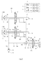
- FIG. 2 is a circuit diagram illustrating a hydraulic circuit according to the embodiment. It is a circuit diagram showing a hydraulic circuit according to a modification.
- FIG. 1 is a circuit diagram showing a hydraulic circuit 10 according to the embodiment.
- the hydraulic circuit 10 shown in FIG. 1 is mounted on a construction machine (particularly, a small construction machine).
- the construction machine includes a working device attached to a vehicle body, and a required work is performed by operating the working device.
- the construction machine is a tracked vehicle provided with a pair of right and left crawlers, and is capable of running on its own. Excavators and crane trucks can be exemplified as such construction machines.
- the hydraulic circuit 10 includes one or more first actuators 11 and one or more second actuators 12. Alternatively, the hydraulic circuit 10 drives one or more first actuators 11 and one or more second actuators 12 provided on the construction machine. FIG. 1 shows only one second actuator 12 for simplicity. Each of the actuators 11 and 12 is of a hydraulic type.
- the cab of the construction machine is provided with one or more first operating devices 2 and one or more second operating devices 3 operated by an operator.
- the one or more first operating devices 2 correspond to the one or more first actuators 11, respectively.
- the corresponding first actuator 11 operates in an operation direction adapted to the operation direction.
- the relationship between the one or more second operating devices 3 and the second actuators 12 is the same.
- the first actuator 11 is a driving actuator
- the second actuator 12 is a working device actuator
- the one or more first actuators 11 include a left running motor 11L for driving a left starting wheel 1L provided on a left crawler and a right running motor 11R for driving a right starting wheel 1R provided on a right crawler.
- Each first actuator 11 is a hydraulic motor rotatable in both directions (forward and backward directions), and includes a pair of supply / discharge ports 11a and 11b.
- the one or more second actuators 12 include a turning motor that turns the working device together with the cab, an arm cylinder that drives an arm provided in the working device, and a bucket cylinder that drives a bucket provided in the working device. And so on.
- FIG. 1 shows a double-acting hydraulic cylinder having two supply / discharge ports 12 a and 12 b as an example of the second actuator 12.
- the one or more first operating devices 2 include a left traveling motor 2L for rotating the left traveling motor 11L and thus the left starting wheel 1L in the forward direction or the backward direction, and a right traveling motor 11R and thus the right activation wheel 1R in the forward or backward direction.
- a right traveling controller 2R that rotates in the reverse direction is included.
- the first operating device 2 for traveling is a pedal type
- the second operating device 3 for a working device is a lever type. Thereby, the operator is allowed to operate the first operating device 2 and the second operating device 3 at the same time using the limbs.
- the construction machine may be equipped with a control device attached to the hydraulic circuit 10 (in other words, the construction machine is equipped with a hydraulic system including the hydraulic circuit 10 and a control device attached thereto. May be).
- the control device may electronically control the operation of the hydraulic components constituting the hydraulic circuit 10 according to the output of a sensor that detects the operation amount and / or operation direction of each of the operation devices 2 and 3.
- the hydraulic circuit 10 includes a pump 13, a tank 14, a first pump line 15, a second pump line 16, a tank line 17, one or more first directional control valves 21, one or more pressure compensating valves 22, one or more pairs.
- the system includes first supply / discharge lines 23, 24, one or more second directional control valves 31, a priority valve 32, and one or more pairs of second supply / discharge lines 33, 34.
- the pump 13 sucks the working oil stored in the tank 14 and discharges the pressure oil from its discharge port 13a.
- the pump 13 is a pressure oil source for the actuators 11 and 12.
- One first directional control valve 21, one pressure compensating valve 22, a pair of first supply / discharge lines 23 and 24, and one first actuator 11 constitute one module.
- the first directional control valve 21 has a pump port 21p and a pair of supply / discharge ports 21a and 21b.
- the pump port 21p is connected to the discharge port 13a of the pump 13 via the first pump line 15.
- the supply / discharge port 21a is connected to the supply / discharge port 11a of the corresponding first actuator 11 via a supply / discharge line 23, and the supply / discharge port 21b is connected to the supply / discharge of the corresponding first actuator 11 via the supply / discharge line 24.
- the first direction switching valve 21 further has a tank port 21t, and the tank port 21t is connected to the tank 14 via the tank line 17 (the same applies to other tank ports described later).
- the pump port 21p When the operation for operating the first actuator 11 is performed, the pump port 21p is connected to one of the supply / discharge ports 21a and 21b.
- This “connection” includes not only communication between ports completed in the first directional control valve 21 but also connection via an oil passage outside the first directional control valve 21.
- the first directional control valve 21 further has a primary port 21q and a secondary port 21r.
- the primary port 21q of the first directional control valve 21 is connected to the corresponding primary port 22a of the corresponding pressure compensating valve 22 via a primary compensation line 25 disposed outside the first directional control valve 21.
- the secondary port 22b of the pressure compensating valve 22 is connected to a corresponding secondary port 21r of the first directional switching valve 21 via a secondary compensation line 26 provided outside the first directional switching valve 21.
- the secondary port 21r communicates with one of the supply / discharge ports 21a and 21b in the first direction switching valve 21 according to the operation direction according to the operation direction.
- the pump port 21p is connected to one of the supply / discharge ports 21a and 21b via the primary port 21q, the corresponding primary compensation line 25, the corresponding pressure compensation valve 22, the corresponding secondary compensation line 26, and the secondary port 21r. Connected to.
- the second pump line 16 branches off from the first pump line 15.
- a priority valve 32 is provided on the second pump line 16.
- the second pump line 16 includes an upstream portion 16a connecting the first pump line 15 to an inlet port 32a of the priority valve 32, and a downstream portion 16b connected to an outlet port 32b of the priority valve 32.
- One second directional control valve 31, a pair of second supply / discharge lines 33 and 34, and one second actuator 12 constitute one module.
- the second direction switching valve 31 has a pump port 31p and a pair of supply / discharge ports 31a, 31b.
- the pump port 31p is connected to the outlet port 32b of the priority valve 32 via the downstream portion 16b of the second pump line 16.
- the second pump line 16 branches off from the first pump line 15 and is connected to the pump port 31p of the second directional control valve 31.
- the supply / discharge port 31a is connected to the supply / discharge port 12a of the second actuator 12 via the second supply / discharge line 33, and the supply / discharge port 31b is connected to the supply / discharge of the second actuator 12 via the second supply / discharge line 34. Connected to port 12b.
- a poppet is interposed in one of the supply / discharge lines 33 and 34 connected to the rod-side oil chamber, or a line for returning hydraulic oil from the tank 14. May be connected.
- the priority valve 32 is configured to fully open the second pump line 16 when the pressure difference between the discharge pressure of the pump 13 and the load pressure of the first actuator 11 is greater than a set value. Further, when the differential pressure is smaller than the set value, the priority valve 32 is configured to decrease the opening degree of the second pump line 16 as the differential pressure decreases.
- the “differential pressure” is a pressure value obtained by subtracting the load pressure of the first actuator 11 from the discharge pressure of the pump 13. Generally speaking, when the load pressure of the first actuator 11 increases, the action of the priority valve 32 narrows the second pump line 16.
- the priority valve 32 exhibiting such an action is mechanically and hydraulically configured so that the operation of the priority valve 32 does not involve electronic control as much as possible.
- the priority valve 32 includes a valve body that changes the opening of the second pump line 16 and a spring 32c that urges the valve body in the closing direction.
- the “set value” is adjusted by the spring force exerted by the spring 32c.
- the hydraulic pressure of the working oil flowing through the upstream portion 16a of the second pump line 16 (that is, the discharge pressure of the pump 13) acts on the valve body in the opening direction.
- the load pressure of the first actuator 11 acts on the valve body in the closing direction.
- the priority valve 32 is connected to the secondary compensation line 26 via the signal pressure supply line 18 so as to supply the load pressure to the priority valve 32.
- the signal pressure supply line 18 branches off from the secondary compensation line 26 and is connected to the priority valve 32. Thereby, the operating oil pressure flowing through the secondary compensation line 26 is connected to the priority valve 32 as the load pressure of the first actuator 11.
- the signal pressure supply line 18 is composed of a plurality of branch portions 18 a extending from each of the plurality of secondary compensation lines 26, and a plurality of branch portions 18 a that are aggregated into one system to form a priority valve.
- 32 includes a common unit 18b connected to the common unit 18b. The figure shows a state in which the second pump line 16 is closed in the neutral state of the priority valve 32 (the stopped state of the pump 13), but this is merely an example, and the second pump line 16 is opened with a small opening degree. May be.
- the first direction switching valve 21 is a three-position direction switching valve.
- the valve position is changed according to the operation of the first operating device 2, and the communication state (function) of the port is switched.
- a control pressure may be used, or electronic control may be used (the same applies to the second direction switching valve 31).
- the first directional control valve 21 is positioned at the neutral position (see the central function in FIG. 1). Both the pair of supply / discharge ports 21a, 21b are connected to the tank port 21t, and the remaining three ports 21p, 21q, 21r are blocked. Therefore, the supply of the pressure oil to the first actuator 11 stops, the first actuator 11 stops, and the starting wheel 1 stops.
- the first directional control valve 21 When the first operating device 2 is operated in the first direction, the first directional control valve 21 is positioned at the first position (see the upper function in FIG. 1), the pump port 21p is connected to the primary port 21q, and the secondary The port 21r is connected to the supply / discharge port 21a, and the tank port 21t is connected to the supply / discharge port 21b. Pressure oil from the pump 13 is supplied to the supply / discharge port 11 a of the first actuator 11 via the pressure compensation valve 22.
- the starting wheel 1 rotates in a forward direction (counterclockwise as viewed from the left) for moving the vehicle forward.
- the first directional control valve 21 When the first operating device 2 is operated in the second direction, the first directional control valve 21 is positioned at the second position (see the lower function in the figure), the pump port 21p is connected to the primary port 21q, and the secondary port is connected. 21r is connected to the supply / discharge port 21b, and the tank port 21t is connected to the supply / discharge port 21a. Pressure oil from the pump 13 is supplied to the supply / discharge port 11 b of the first actuator 11 via the pressure compensation valve 22. As an example, the starting wheel 1 rotates in a reverse direction (clockwise in a left side view) for moving the vehicle backward.
- the pump port 21p communicates with the primary port 21q.
- the pressure oil from the pump 13 passes through the primary compensation line 25, the pressure compensation valve 22 and the secondary compensation line 26 (through the first directional control valve 21) to the secondary port 21 r of the first directional control valve 21. Is entered. Therefore, the load pressure of the first actuator 11 (the hydraulic pressure in the secondary compensation line 26, the secondary pressure of the pressure compensating valve 22) is supplied to the priority valve 32. Thereby, the valve body of the priority valve 32 is urged in the closing direction in combination with the urging force of the spring.
- the load pressure is not supplied to the priority valve 32.
- the pressure oil from the pump 13 is supplied to an upstream portion 16 a of the second pump line 16.
- the operating oil pressure (that is, the discharge pressure of the pump 13) flowing through the upstream portion 16a acts on the valve element of the priority valve 32.
- the differential pressure between the discharge pressure of the pump 13 and the load pressure exceeds the set value adjusted by the spring force of the spring, so that the priority valve 32 is fully opened.
- the pressure oil from the pump 13 is supplied to the second direction switching valve 31 via the upstream section 16a, the priority valve 32, and the downstream section 16b.
- the second directional control valve 31 is a three-position directional control valve. The valve position changes according to the operation of the second operating device 3, and the communication state (function) of the port switches.
- the second directional control valve 31 is positioned at the center position, and the four ports 31a, 31b, 31p, 31t are blocked.
- the supply of the pressure oil to the second actuator 12 stops, and the second actuator 12 stops.
- the second direction switching valve 31 is positioned at the first position (see the upper function in FIG. 1).
- the pump port 31p is connected to the supply / discharge port 31a, and the tank port 31t is connected to the supply / discharge port 31b.
- Pressure oil from the pump 13 is supplied to the supply / discharge port 12a of the second actuator 12, and the working device operates in one direction.
- the second directional control valve 31 When the second operating device 3 is operated in the second direction, the second directional control valve 31 is positioned at the second position (see the lower function in FIG. 1), the pump port 31p is connected to the supply / discharge port 31b, and the tank The port 31t is connected to the supply / discharge port 31a. Pressure oil from the pump 13 is supplied to the supply / discharge port 12b of the second actuator 12, and the working device operates in a direction opposite to the one direction.
- the valve positions of the first directional control valve 21 and the second directional control valve 31 are switched from the neutral position.
- the load pressure of the first actuator 11 is supplied to the priority valve 32 via the signal pressure supply line 18.
- the discharge pressure of the pump 13 acts on the valve body of the priority valve 32 in the opening direction
- the spring force of the spring 32c and the load pressure of the first actuator 11 act on the closing direction.
- the differential pressure between the discharge pressure of the pump 13 and the load pressure of the first actuator 11 is smaller than a set value (adjusted by the spring force of the spring), the opening of the second pump line 16 defined by the position of the valve body The degree decreases.
- the throttle amount of the second pump line 16 set in the priority valve 32 increases.
- the flow rate flowing through the first directional control valve 21 and thus the first actuator 11 is preferentially secured. For this reason, it is possible to suppress a decrease in the operation speed of the first actuator 11 that is relatively large in load.
- the first actuator 11 is a traveling motor
- the second actuator 12 is a hydraulic actuator for a working device.
- one-pump system it is possible to prevent both operating speeds of different types of actuators from decreasing.
- one priority valve 32 for changing the opening degree of the second pump line 16 is provided on the second pump line 16 branched from the first pump line 15, and the priority valve 32 has the first actuator 11 as a control pressure.
- a signal pressure supply line 18 for supplying the load pressure.
- the pressure compensating valve 22 (see also FIG. 1) can be omitted.
- the structure of the first directional control valve 21 may be the same as that of the above-described embodiment as in the modified example shown in FIG. 2 or may be changed.
- the connecting oil passage 25A connects the primary port 21q to the secondary port 21r. Connecting.
- the signal pressure supply line 18 branches from the connection oil passage 25A and is connected to the priority valve 32.
- the hydraulic pressure flowing through the connection oil passage 25A is supplied to the priority valve 32 as the load pressure of the first actuator (traveling motor). Also in this modified example, it is possible to prevent both the traveling speed and the operating speed of the working device from decreasing at the same time as the operation is performed, and to keep the traveling speed high.
- the first actuator may be a working device actuator
- the second actuator may be a traveling actuator.
- the load pressure of the working device actuator is high during the parallel operation, the flow rate to the working device actuator is preferentially ensured, and the operation speed of the working device can be maintained high.
Landscapes
- Engineering & Computer Science (AREA)
- General Engineering & Computer Science (AREA)
- Mining & Mineral Resources (AREA)
- Civil Engineering (AREA)
- Structural Engineering (AREA)
- Physics & Mathematics (AREA)
- Fluid Mechanics (AREA)
- Mechanical Engineering (AREA)
- Fluid-Pressure Circuits (AREA)
- Operation Control Of Excavators (AREA)
Priority Applications (3)
| Application Number | Priority Date | Filing Date | Title |
|---|---|---|---|
| DE112019004044.8T DE112019004044T5 (de) | 2018-08-10 | 2019-08-01 | Hydraulikkreislauf einer baumaschine |
| CN201980048928.8A CN112424485A (zh) | 2018-08-10 | 2019-08-01 | 工程机械的油压回路 |
| US17/262,838 US11131080B2 (en) | 2018-08-10 | 2019-08-01 | Hydraulic circuit of construction machine |
Applications Claiming Priority (2)
| Application Number | Priority Date | Filing Date | Title |
|---|---|---|---|
| JP2018-151071 | 2018-08-10 | ||
| JP2018151071A JP6964052B2 (ja) | 2018-08-10 | 2018-08-10 | 建設機械の油圧回路 |
Publications (1)
| Publication Number | Publication Date |
|---|---|
| WO2020031816A1 true WO2020031816A1 (ja) | 2020-02-13 |
Family
ID=69414219
Family Applications (1)
| Application Number | Title | Priority Date | Filing Date |
|---|---|---|---|
| PCT/JP2019/030113 Ceased WO2020031816A1 (ja) | 2018-08-10 | 2019-08-01 | 建設機械の油圧回路 |
Country Status (5)
| Country | Link |
|---|---|
| US (1) | US11131080B2 (enExample) |
| JP (1) | JP6964052B2 (enExample) |
| CN (1) | CN112424485A (enExample) |
| DE (1) | DE112019004044T5 (enExample) |
| WO (1) | WO2020031816A1 (enExample) |
Families Citing this family (4)
| Publication number | Priority date | Publication date | Assignee | Title |
|---|---|---|---|---|
| US11713775B2 (en) * | 2020-08-18 | 2023-08-01 | Deere & Company | Agricultural implements and hydraulic circuits therefor incorporating one or more priority valves |
| JP7784927B2 (ja) | 2022-03-15 | 2025-12-12 | 川崎重工業株式会社 | 液圧駆動装置 |
| CN118843750A (zh) * | 2022-03-15 | 2024-10-25 | 川崎重工业株式会社 | 液压驱动装置 |
| WO2023176732A1 (ja) * | 2022-03-15 | 2023-09-21 | 川崎重工業株式会社 | 液圧駆動装置 |
Citations (2)
| Publication number | Priority date | Publication date | Assignee | Title |
|---|---|---|---|---|
| JPS58153829A (ja) * | 1982-03-08 | 1983-09-13 | Kobe Steel Ltd | 油圧シヨベルの油圧回路 |
| JP2017190799A (ja) * | 2016-04-11 | 2017-10-19 | キャタピラー エス エー アール エル | 作業機械の流体圧回路 |
Family Cites Families (5)
| Publication number | Priority date | Publication date | Assignee | Title |
|---|---|---|---|---|
| JP2948064B2 (ja) | 1993-09-06 | 1999-09-13 | 日立建機株式会社 | 建設機械の油圧駆動装置 |
| US5950429A (en) * | 1997-12-17 | 1999-09-14 | Husco International, Inc. | Hydraulic control valve system with load sensing priority |
| US20140060032A1 (en) * | 2011-03-15 | 2014-03-06 | Husco International, Inc. | Multiple function hydraulic system with a variable displacement pump and a hydrostatic pump-motor |
| WO2016085959A1 (en) * | 2014-11-24 | 2016-06-02 | Parker-Hannifin Corporation | System architectures for steering and work functions in a wheel loader |
| CN105201944B (zh) * | 2015-09-25 | 2017-10-03 | 广西柳工机械股份有限公司 | 流量放大阀及转向液压系统 |
-
2018
- 2018-08-10 JP JP2018151071A patent/JP6964052B2/ja active Active
-
2019
- 2019-08-01 CN CN201980048928.8A patent/CN112424485A/zh active Pending
- 2019-08-01 US US17/262,838 patent/US11131080B2/en active Active
- 2019-08-01 WO PCT/JP2019/030113 patent/WO2020031816A1/ja not_active Ceased
- 2019-08-01 DE DE112019004044.8T patent/DE112019004044T5/de active Pending
Patent Citations (2)
| Publication number | Priority date | Publication date | Assignee | Title |
|---|---|---|---|---|
| JPS58153829A (ja) * | 1982-03-08 | 1983-09-13 | Kobe Steel Ltd | 油圧シヨベルの油圧回路 |
| JP2017190799A (ja) * | 2016-04-11 | 2017-10-19 | キャタピラー エス エー アール エル | 作業機械の流体圧回路 |
Also Published As
| Publication number | Publication date |
|---|---|
| US11131080B2 (en) | 2021-09-28 |
| JP6964052B2 (ja) | 2021-11-10 |
| US20210140144A1 (en) | 2021-05-13 |
| JP2020026828A (ja) | 2020-02-20 |
| DE112019004044T5 (de) | 2021-05-06 |
| CN112424485A (zh) | 2021-02-26 |
Similar Documents
| Publication | Publication Date | Title |
|---|---|---|
| KR101820324B1 (ko) | 파이프 레이어용 유압회로 | |
| US7513109B2 (en) | Hydraulic controller for working machine | |
| JP4232784B2 (ja) | 作業機械の油圧制御装置 | |
| JP6730798B2 (ja) | 油圧駆動装置 | |
| WO2020031816A1 (ja) | 建設機械の油圧回路 | |
| JPWO2016208530A1 (ja) | 建設・輸送・農業機械のステアリング装置 | |
| JP2016156426A (ja) | アンロード弁および油圧ショベルの油圧駆動システム | |
| JP6776334B2 (ja) | ショベル及びショベル用コントロールバルブ | |
| US11078646B2 (en) | Shovel and control valve for shovel | |
| JP6196567B2 (ja) | 建設機械の油圧駆動システム | |
| JP2006329341A (ja) | 作業機械の油圧制御装置 | |
| US11242671B2 (en) | Hydraulic circuit of construction machine | |
| JP2016133206A (ja) | 建設機械の油圧回路 | |
| WO2015115428A1 (ja) | 作業機の制御システム及び低圧選択回路 | |
| JP2019183972A (ja) | 作業車両の油圧回路 | |
| WO2017164169A1 (ja) | ショベル及びショベル用コントロールバルブ | |
| JP2007120512A (ja) | 作業機械の油圧制御装置 | |
| JP2018054031A (ja) | 作業車両用油圧制御装置 | |
| JP4926627B2 (ja) | 電油システム | |
| US12497760B2 (en) | Hydraulic drive apparatus | |
| JP4118893B2 (ja) | 油圧回路 | |
| WO2023176732A1 (ja) | 液圧駆動装置 | |
| JP2023076907A (ja) | 産業車両の油圧システム | |
| JP2011075024A (ja) | 油圧回路装置 |
Legal Events
| Date | Code | Title | Description |
|---|---|---|---|
| 121 | Ep: the epo has been informed by wipo that ep was designated in this application |
Ref document number: 19846765 Country of ref document: EP Kind code of ref document: A1 |
|
| 122 | Ep: pct application non-entry in european phase |
Ref document number: 19846765 Country of ref document: EP Kind code of ref document: A1 |