WO2020031764A1 - 車載通信装置、通信プログラム及びメッセージ送信方法 - Google Patents
車載通信装置、通信プログラム及びメッセージ送信方法 Download PDFInfo
- Publication number
- WO2020031764A1 WO2020031764A1 PCT/JP2019/029585 JP2019029585W WO2020031764A1 WO 2020031764 A1 WO2020031764 A1 WO 2020031764A1 JP 2019029585 W JP2019029585 W JP 2019029585W WO 2020031764 A1 WO2020031764 A1 WO 2020031764A1
- Authority
- WO
- WIPO (PCT)
- Prior art keywords
- message
- communication
- group
- processing unit
- buffer
- Prior art date
- Legal status (The legal status is an assumption and is not a legal conclusion. Google has not performed a legal analysis and makes no representation as to the accuracy of the status listed.)
- Ceased
Links
Images






Classifications
-
- H—ELECTRICITY
- H04—ELECTRIC COMMUNICATION TECHNIQUE
- H04L—TRANSMISSION OF DIGITAL INFORMATION, e.g. TELEGRAPHIC COMMUNICATION
- H04L51/00—User-to-user messaging in packet-switching networks, transmitted according to store-and-forward or real-time protocols, e.g. e-mail
- H04L51/21—Monitoring or handling of messages
- H04L51/214—Monitoring or handling of messages using selective forwarding
-
- B—PERFORMING OPERATIONS; TRANSPORTING
- B60—VEHICLES IN GENERAL
- B60R—VEHICLES, VEHICLE FITTINGS, OR VEHICLE PARTS, NOT OTHERWISE PROVIDED FOR
- B60R16/00—Electric or fluid circuits specially adapted for vehicles and not otherwise provided for; Arrangement of elements of electric or fluid circuits specially adapted for vehicles and not otherwise provided for
- B60R16/02—Electric or fluid circuits specially adapted for vehicles and not otherwise provided for; Arrangement of elements of electric or fluid circuits specially adapted for vehicles and not otherwise provided for electric constitutive elements
- B60R16/023—Electric or fluid circuits specially adapted for vehicles and not otherwise provided for; Arrangement of elements of electric or fluid circuits specially adapted for vehicles and not otherwise provided for electric constitutive elements for transmission of signals between vehicle parts or subsystems
-
- H—ELECTRICITY
- H04—ELECTRIC COMMUNICATION TECHNIQUE
- H04L—TRANSMISSION OF DIGITAL INFORMATION, e.g. TELEGRAPHIC COMMUNICATION
- H04L12/00—Data switching networks
- H04L12/28—Data switching networks characterised by path configuration, e.g. LAN [Local Area Networks] or WAN [Wide Area Networks]
-
- H—ELECTRICITY
- H04—ELECTRIC COMMUNICATION TECHNIQUE
- H04L—TRANSMISSION OF DIGITAL INFORMATION, e.g. TELEGRAPHIC COMMUNICATION
- H04L12/00—Data switching networks
- H04L12/28—Data switching networks characterised by path configuration, e.g. LAN [Local Area Networks] or WAN [Wide Area Networks]
- H04L12/46—Interconnection of networks
-
- H—ELECTRICITY
- H04—ELECTRIC COMMUNICATION TECHNIQUE
- H04L—TRANSMISSION OF DIGITAL INFORMATION, e.g. TELEGRAPHIC COMMUNICATION
- H04L51/00—User-to-user messaging in packet-switching networks, transmitted according to store-and-forward or real-time protocols, e.g. e-mail
- H04L51/21—Monitoring or handling of messages
- H04L51/226—Delivery according to priorities
Definitions
- the present disclosure relates to an in-vehicle communication device that performs communication in a vehicle, a communication program executed by the in-vehicle communication device, and a message transmission method by the in-vehicle communication device.
- ECUs Electronic Control Units
- Each ECU communicates with other ECUs to exchange information, and performs each process. Therefore, as the number of ECUs in the vehicle increases, the amount of communication lines in the vehicle provided for the ECUs to communicate increases, increasing the weight of the vehicle and reducing the space for arranging the communication lines in the vehicle. And so on.
- Patent Literature 1 a vehicle control in which the inside of a vehicle is divided into a plurality of regions, a plurality of functional ECUs are connected to a relay ECU via a first network for each region, and a plurality of relay ECUs are connected via a second network. The system has been described.
- the present disclosure has been made in view of such circumstances, and an object of the present disclosure is to provide an in-vehicle communication device, a communication program, and a message transmission method that can expect effective use of a communication band or reduction of a communication delay. Is to do.
- the in-vehicle communication device includes a classification processing unit that performs a process of classifying a message to be transmitted to another device into a plurality of groups, a group selected in a predetermined order, and a message classified into the selected group. And a message transmitting unit that transmits the message to the other device.
- the communication program the vehicle-mounted communication device, classified messages to be transmitted to other devices into a plurality of groups, select a group in a predetermined order, the message classified into the selected group and the other To perform the transmission to the other device.
- the message transmission method classifies messages to be transmitted to another device into a plurality of groups, selects a group in a predetermined order, and transmits the messages classified into the selected group to the other device. I do.
- the present application can be realized not only as an in-vehicle communication device having such a characteristic processing unit, but also as a message transmission method including such characteristic processing as a step, or executing such a step on a computer. Or a communication program for causing the program to execute. Further, the present invention can be realized as a semiconductor integrated circuit that realizes a part or all of the vehicle-mounted communication device, or as another device or system including the vehicle-mounted communication device.
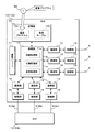
- FIG. 1 is a block diagram illustrating a configuration of a vehicle-mounted communication system according to the present embodiment.
- FIG. 3 is a block diagram illustrating a configuration of a GW according to the present embodiment.
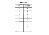
- FIG. 3 is a schematic diagram illustrating a configuration example of a load table.
- FIG. 6 is a schematic diagram for explaining an example of a criterion for determining a communication load of a message.
- FIG. 9 is a schematic diagram for explaining a process of transmitting a message to another GW performed by the GW according to the present embodiment.
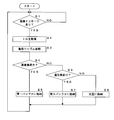
- 9 is a flowchart illustrating a procedure of a message classification process performed by the GW according to the present embodiment.
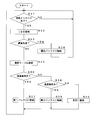
- FIG. 9 is a flowchart illustrating a procedure of a message transmission process performed by the GW according to the present embodiment.
- 15 is a flowchart illustrating a procedure of a load table update process performed by the GW according to the first modification.
- FIG. 14 is a schematic diagram for explaining a process of transmitting a message to another GW performed by the GW according to Modification 2.
- 15 is a flowchart illustrating a procedure of a message classification process performed by a GW according to Modification 2.
- 15 is a flowchart illustrating a procedure of a message transmission process performed by a GW according to Modification 2.
- the in-vehicle communication device includes a classification processing unit that performs a process of classifying a message to be transmitted to another device into a plurality of groups, selects a group in a predetermined order, and classifies the message into the selected group And a message transmitting unit for transmitting the received message to the another device.
- the messages to be transmitted to the other devices by the in-vehicle communication device are classified into a plurality of groups.
- the in-vehicle communication device selects one group from the plurality of groups in a predetermined order, and transmits a message classified into the selected group to another device.
- the message transmission unit is connected to the other device via a plurality of communication lines, and that the message transmission unit selects a group in a predetermined order for each communication line and transmits the message.
- the in-vehicle communication device and one other device are connected via a plurality of communication lines.
- the communication band between the in-vehicle communication device and another device can be expanded.
- group selection and message transmission are performed for each communication line.
- the widened communication band can be used effectively.
- the classification processing unit classifies a message to be transmitted to another device into a first group and a second group, and the message transmission unit includes a message classified into the first group and the second group. It is preferable to alternately transmit the message classified to the other device to the other device.
- the messages are classified into two groups, a first group and a second group.
- the in-vehicle communication device transmits a message classified into the first group and a message classified into the second group alternately.
- the classification can be facilitated.
- the classification processing unit performs classification according to the magnitude of the message communication load.
- the in-vehicle communication device transmits the messages classified according to the communication load in a predetermined order, and can expect effective use of the communication band.
- the message includes identification information
- the classification processing unit performs classification based on the correspondence information between the identification information of the message and the communication load, and based on a transmission history of the message to the other device, It is preferable to include an updating unit that updates the correspondence information.
- the message transmitted and received by the in-vehicle communication device includes identification information indicating the type of information included in the message or the source of the message.
- the in-vehicle communication device stores correspondence information between the identification information of the message and the communication load related to the message, and classifies the message to be transmitted into a plurality of groups based on the correspondence information.
- the in-vehicle communication device updates the correspondence information based on the message transmission history. This allows the in-vehicle communication device to perform classification in response to a change in the communication status or the like.
- the message includes priority information
- the message transmitting unit preferentially transmits a message having a predetermined priority regardless of the classification of the plurality of groups.
- the message transmitted and received by the in-vehicle communication device includes priority information indicating the priority of the message.
- the priority information may also serve as the identification information.
- the in-vehicle communication device preferentially transmits a message of a predetermined priority regardless of the classification of the plurality of groups. This can prevent a message to be transmitted with priority from being delayed.
- the communication program according to this aspect is that the message to be transmitted to the in-vehicle communication device is classified into a plurality of groups, the groups are selected in a predetermined order, and the messages classified into the selected group are selected. Is transmitted to the other device.
- the message to be transmitted to another device is classified into a plurality of groups, the groups are selected in a predetermined order, and the messages classified into the selected group are sorted by the other groups. Send to device.
- FIG. 1 is a block diagram showing a configuration of the in-vehicle communication system according to the present embodiment.
- the in-vehicle communication system 1 according to the first embodiment includes a vehicle 100 including a plurality of ECUs 3 and a plurality of GWs (Gate Ways) 10.
- the plurality of ECUs 3 and the GW 10 transmit and receive messages via the communication lines 5 and 6. System.
- two GWs 10 are mounted on a vehicle 100, two GWs 10 are connected via three communication lines 6, three communication lines 5 are connected to each GW 10, and three GWs are connected to each communication line.
- the configuration of the vehicle-mounted communication system 1 to which the ECU 3 is connected is shown.
- the two GWs 10 when it is necessary to distinguish between the two GWs 10, one is designated as a GW 10a and the other is designated as a GW 10b as shown in FIG. Similarly, the three communication lines 6 are distinguished as 6a, 6b, and 6c as necessary.
- the number of ECUs 3, the number of GCWs 10, the number of communication lines 5 and 6, the connection mode of the devices, the network configuration, and the like included in the in-vehicle communication system 1 are not limited to those illustrated.
- the ECU 3 mounted on the vehicle 100 includes, for example, an ECU that controls the operation of an engine of the vehicle 100, an ECU that controls locking / unlocking of a door, an ECU that controls turning on / off of a light, and an ECU that controls the operation of an airbag. And various ECUs such as an ECU that controls the operation of an ABS (Antilock Brake System).
- Each ECU 3 is connected to one of the communication lines 5 arranged in the vehicle 100, and can transmit and receive messages to and from another ECU 3 via the communication line 5 and the GW 10.
- Each GW 10 is connected to a plurality of communication lines 5, and can transmit and receive messages to and from a plurality of ECUs 3 via the communication lines 5.
- the GW 10 that has received the message transmitted by the ECU 3 determines whether relaying is necessary based on the ID attached to the received message, and transmits the message that requires relaying from the communication line 5 different from the receiving source. For this reason, the GW 10 has a transmission destination map that stores the correspondence between the ID assigned to the message and the communication line 5 to which the message is transmitted.
- a message can be transmitted from the ECU 3 connected to one GW 10a to the ECU 3 connected to the other GW 10b.
- the GW 10a that has received the message from the ECU 3 determines that the message should be relayed to the other GW 10b based on the ID attached to this message, and outputs this message to the GW 10b by outputting the message from the communication line 6.
- the GW 10b that has received the message from the GW 10a via the communication line 6 determines which of the relay destination communication lines 5 is based on the ID attached to the received message, and transmits this message to the relay destination communication line. Send from 5.
- two GWs 10 are connected via three communication lines 6.
- the three communication lines 6 follow the same communication standard.
- a communication standard such as CAN (Controller Area Network), Ethernet (registered trademark), or FlexRay can be adopted.
- CAN Controller Area Network
- Ethernet registered trademark
- FlexRay FlexRay
- the GW 10 When the GW 10 transmits a message to another GW 10, any one of the three communication lines 6 is selected, and the message is transmitted from the selected communication line 6.
- the GW 10 according to the present embodiment classifies a message to be transmitted to another GW 10 into a first group having a large communication load and a second group having a small communication load according to the communication load of the message.
- the GW 10 alternately transmits a message with a large communication load and a message with a small communication load for each communication line 6.
- FIG. 2 is a block diagram showing a configuration of GW 10 according to the present embodiment. Since the two GWs 10 included in the in-vehicle communication system 1 according to the present embodiment have substantially the same configuration, FIG. 2 illustrates only one GW 10a in detail, and the other GW 10b illustrates the detailed configuration. Is omitted.
- the GW 10 according to the present embodiment includes a processing unit (processor) 11, a storage unit (storage) 12, communication units (transceivers) 13, 14, connection units (connectors) 15, 16, a communication buffer 17, and the like. ing.
- the processing unit 11 is configured using an arithmetic processing device such as a CPU (Central Processing Unit) or an MPU (Micro-Processing Unit).
- the processing unit 11 can perform various processes by reading and executing the program stored in the storage unit 12.
- the processing unit 11 reads out and executes the communication program 12a stored in the storage unit 12, thereby processing to relay a message between the communication lines 5 and classifies a message to be transmitted to another GW 10. Processing and processing for transmitting the classified message to another GW 10 are performed.
- the storage unit 12 is configured using a nonvolatile memory element such as a flash memory or an EEPROM (Electrically Erasable Programmable Read Only Memory).
- the storage unit 12 stores various programs executed by the processing unit 11 and various data necessary for processing of the processing unit 11.
- the storage unit 12 stores a communication program 12a executed by the processing unit 11 and a load table 12b used when the processing unit 11 classifies transmission messages to other GWs 10.
- the communication program 12a may be written in the storage unit 12 at the stage of manufacturing the GW 10, for example, and the GW 10 may acquire a program distributed by a remote server device or the like by communication.
- the program recorded on the recording medium 99 such as an optical disk may be read by the GW 10 and stored in the storage unit 12.
- the program recorded on the recording medium 99 may be read by the writing device and written into the storage unit 12 of the GW 10. May be.
- the communication program 12a may be provided in a form of distribution via a network, or may be provided in a form recorded on the recording medium 99.
- FIG. 3 is a schematic diagram showing one configuration example of the load table 12b.
- the load table 12b stored in the storage unit 12 by the GW 10 according to the present embodiment is a table in which an ID assigned to a message that can be transmitted and received by the GW 10 is associated with a communication load of the message.
- the message communication load is indicated in three stages of “large”, “medium” and “small”, but is not limited to this. The number of stages may be four or more.
- the load table 12b is used for a message classification process described later. In this classification process, the messages are classified into two groups, a first group and a second group, according to the communication load.
- the classification destination (that is, the first group or the second group) for the message ID may be stored in the load table 12b.
- the load table 12b is created in advance in the design stage of the GW 10, the in-vehicle communication system 1, the vehicle 100, or the like, and is written in the storage unit 12 in the manufacturing process of the GW 10.
- FIG. 4 is a schematic diagram for explaining an example of a criterion for determining the communication load of a message.
- the load table 12b is created in advance by the designer of the GW 10 or the in-vehicle communication system 1 based on the criteria shown in FIG.
- the communication load of this message is determined in three stages based on the data length of the message and the transmission cycle of the message.
- the data length of the message is determined to be either "long” or “short” by comparing it with a predetermined threshold value such as X bytes.
- the transmission period of the message is determined to be either “long” or “short” by comparing it with a predetermined threshold value such as Y milliseconds, for example.
- a message having a short data length and a long transmission cycle is determined to have a small communication load, and a message having a long data length and a short transmission cycle is determined to have a large communication load.
- a message having a short data length and a short transmission cycle and a message having a long data length and a long transmission cycle are determined to have medium communication loads.
- connection portions 15 and 16 are used to detachably connect the communication lines 5 and 6, and are so-called connectors.
- the connection portions 15 and 16 are configured to be suitable for the shapes and standards of the communication lines 5 and 6 to be connected.
- FIG. 2 three connecting portions 15 for connecting the communication line 5 for communicating with the ECU 3 and three connecting portions 16 for connecting the communication line 6 for communicating with another GW 10 are shown. Are shown with different reference numerals.
- the connection portions 15 and 16 are substantially the same. It may be.
- the communication units 13 and 14 perform processing related to transmission and reception of messages via the communication lines 5 and 6 connected to the connection units 15 and 16.
- the communication units 13 and 14 can be configured using a communication IC, for example.
- the communication units 13 and 14 periodically convert the electrical signals on the communication lines 5 and 6 into digital data by periodically sampling and acquiring the potentials of the communication lines 5 and 6 connected to the connection units 15 and 16. This digital data is provided to the processing unit 11 as a received message.
- the communication units 13 and 14 convert a message given as digital data from the processing unit 11 into an electric signal, and output the converted electric signal to communication lines 5 and 6 connected to the connection units 15 and 16, respectively. , Send a message.
- the communication buffer 17 is configured by using a data rewritable memory element such as an SRAM (Static Random Access Memory) or a DRAM (Dynamic Random Access Memory).
- the communication buffer 17 temporarily stores a message received from the ECU 3 or another GW 10.
- a data rewritable memory element such as an SRAM (Static Random Access Memory) or a DRAM (Dynamic Random Access Memory).
- the communication buffer 17 temporarily stores a message received from the ECU 3 or another GW 10.
- a data rewritable memory element such as an SRAM (Static Random Access Memory) or a DRAM (Dynamic Random Access Memory).
- SRAM Static Random Access Memory
- DRAM Dynamic Random Access Memory
- the processing unit 11 reads out and executes the communication program 12a stored in the storage unit 12, so that the relay processing unit 11a, the classification processing unit 11b, the transmission processing unit 11c, 11 is realized as a software-like functional block.
- the relay processing unit 11a performs a process of relaying the message from the ECU 3 received by the communication unit 13 to another ECU 3.
- the relay processing unit 11a acquires the ID attached to the message received by the communication unit 13, refers to the destination map, and checks the destination map for the destination associated with the ID.
- the relay processing unit 11a gives the message to the communication unit 13 of the transmission destination specified by the transmission destination map, and causes the communication unit 13 to transmit the message to the communication line 5.
- the relay processing unit 11a gives a message to be transmitted to the other GW 10 to the classification processing unit 11b.
- the classification processing unit 11b determines the message based on the ID given to the message and the load table 12b stored in the storage unit 12. A process of classifying the message into one of a first group having a large communication load and a second group having a small communication load is performed.
- the classification processing unit 11b classifies messages having a large communication load into a first group, and classifies messages having a small communication load into a second group.
- the classification processing unit 11b may appropriately classify a message having a medium communication load with respect to the first group or the second group.
- the classification processing unit 11b may, for example, alternately classify messages with a medium communication load into a first group or a second group, or randomly classify messages with a medium communication load into a first group or a second group, for example. And may be classified by other methods.
- the classification processing unit 11b stores the messages classified into the first group in the first buffer of the communication buffer 17, and stores the messages classified into the second group in the second buffer of the communication buffer 17.
- the first buffer and the second buffer are FIFO (First @ In @ First @ Out) buffers.
- the transmission processing unit 11c acquires a message to be transmitted to another GW 10 classified by the classification processing unit 11b from the first buffer and the second buffer of the communication buffer 17, and provides the communication unit 14 with the message. Perform the following processing.
- the transmission processing unit 11c alternately acquires a message from the first buffer and the second buffer and supplies the message to the communication unit 14.
- the communication unit 14 transmits the message to another GW 10 by outputting the message given from the processing unit 11 to the communication line 6 connected to the connection unit 16 corresponding to the communication unit 14.
- one transmission processing unit 11c is shown, but the processing unit 11 of the GW 10 is provided with the same number of transmission processing units 11c as the communication units 14 that communicate with other GWs 10. That is, in the present embodiment, three transmission processing units 11c are provided in the processing unit 11. The three transmission processing units 11c perform the above processing independently and in parallel. Each transmission processing unit 11c acquires a message from the first buffer and the second buffer, and transmits the message by giving the acquired message to the communication unit 14 associated with itself.
- FIG. 5 is a schematic diagram illustrating a process of transmitting a message to another GW 10 performed by the GW 10 according to the present embodiment.
- the GW 10 according to the present embodiment receives a message from the ECU 3 connected via the communication line 5, and relays the message to another ECU 3. At this time, if the ECU 3 that should relay the message is connected to another GW 10, the GW 10 transmits this message to the other GW 10.
- the classification processing unit 11b of the GW 10 converts the message into a first group or a communication group with a large communication load based on the ID attached to the message to be transmitted to another GW 10 and the load table 12b stored in the storage unit 12. It is classified into one of the second groups having a small load.
- the classification processing unit 11b stores the messages classified into the first group in the first buffer 17a of the communication buffer 17, and stores the messages classified into the second group in the second buffer 17b.
- the three transmission processing units 11c provided in association with the three communication units 14 of the GW 10 acquire the messages stored in the first buffer 17a and the second buffer 17b, and provide the acquired messages to the corresponding communication units 14, respectively. , And sends a message to another GW 10.
- each transmission processing unit 11c acquires a message alternately from the first buffer 17a and the second buffer 17b.
- the acquisition of messages from the first buffer 17a and the second buffer 17b by the three transmission processing units 11c is performed asynchronously, in parallel, and exclusively.
- the transmission processing unit 11c may continuously acquire the message from the buffer in which the message is stored.
- each communication unit 14 alternately alternates the first group of messages with a large communication load stored in the first buffer 17a and the second group of messages with a small communication load stored in the second buffer 17b. This will be transmitted to the GW 10.
- FIG. 6 is a flowchart illustrating a procedure of a message classification process performed by the GW 10 according to the present embodiment.
- the classification processing unit 11b of the processing unit 11 of the GW 10 according to the present embodiment determines whether there is a message to be transmitted to another GW 10 (Step S1). If there is no message to be transmitted to another GW 10 (S1: NO), the classification processing unit 11b waits until a message to be transmitted to another GW 10 is given. When there is a message to be transmitted to another GW 10 (S1: YES), the classification processing unit 11b acquires the ID included in this message (Step S2). The classification processing unit 11b refers to the load table 12b stored in the storage unit 12 based on the acquired ID (Step S3).
- the classification processing unit 11b determines whether the communication load of this message is large based on the result of referring to the load table 12b (Step S4). If the communication load is large (S4: YES), the classification processing unit 11b classifies the message into a first group, stores it in the first buffer 17a corresponding to the first group (step S5), and processes to step S1. Back. If the communication load is not large (S4: NO), the classification processing unit 11b determines whether the communication load of this message is small (Step S6). If the communication load is small (S6: YES), the classification processing unit 11b classifies the message into the second group, stores the message in the second buffer 17b corresponding to the second group (step S7), and processes to step S1. Back.
- step S8 if the communication load of this message is not small (S6: NO), that is, if the communication load is medium, the classification processing unit 11b stores the message alternately in either the first buffer 17a or the second buffer 17b. Then (step S8), the process returns to step S1.
- step S8 if the message handled immediately before is stored in the first buffer 17a, the classification processing unit 11b stores the current message in the second buffer 17b, and stores the message handled immediately before in the second buffer 17b. If the message has been stored in the second buffer 17b, the current message is stored in the first buffer 17a.
- the “message handled immediately before” includes not only messages having a medium communication load but also messages having a large communication load and messages having a small communication load. However, the "message handled immediately before” may be limited to a message having a medium communication load.
- FIG. 7 is a flowchart showing a procedure of a message transmission process performed by GW 10 according to the present embodiment. Note that this flowchart is a process individually performed by three transmission processing units 11c provided corresponding to the three communication units 14 of the GW 10. The three transmission processing units 11c execute this processing in parallel.
- the transmission processing unit 11c of the GW 10 determines whether a message is stored in the first buffer 17a (Step S11). If a message is stored in the first buffer 17a (S11: YES), the transmission processing unit 11c acquires this message from the first buffer 17a (Step S12). The transmission processing unit 11c transmits the message to another GW 10 by giving the obtained message to the communication unit 14 (Step S13), and proceeds to Step S14. If no message is stored in the first buffer 17a (S11: NO), the transmission processing unit 11c advances the process to step S14.
- the transmission processing unit 11c determines whether a message is stored in the second buffer 17b (Step S14). If a message is stored in the second buffer 17b (S14: YES), the transmission processing unit 11c acquires this message from the second buffer 17b (Step S15). The transmission processing unit 11c transmits the message to another GW 10 by giving the acquired message to the communication unit 14 (Step S16), and returns the process to Step S11. If no message is stored in the second buffer 17b (S14: NO), the transmission processing unit 11c returns the process to step S11.
- the GW 10 classifies messages to be transmitted to other GWs 10 into two groups, a first group and a second group.
- the GW 10 transmits the message classified into the first group and the message classified into the second group alternately to another GW 10.
- By appropriately classifying the first group and the second group effective use of the communication band between the two GWs 10 or reduction of the communication delay can be expected.
- two GWs 10 are connected via three communication lines 6. Thereby, the communication band between the two GWs 10 can be expanded. Alternate transmission of the messages classified into the first group and the messages classified into the second group is performed for each communication line. Thereby, the communication load can be distributed, and the communication band can be used effectively.
- the message transmitted and received by the in-vehicle communication system 1 according to the present embodiment includes identification information indicating a type of information included in the message or a transmission source of the message.
- the GW 10 according to the present embodiment stores the correspondence information between the message ID and the communication load related to this message in the storage unit 12 as the load table 12b.
- the GW 10 classifies messages to be transmitted to other GWs 10 into a first group and a second group based on the message ID and the load table 12b of the storage unit 12. As a result, the message classification by the GW 10 can be easily set by the load table 12b.
- the GW 10 mounted on the vehicle 100 has been described as an example of the in-vehicle communication device, but the in-vehicle communication device is not limited to the GW 10.
- the ECU 3 may be equipped with the same message classification and transmission functions.
- the in-vehicle communication device may be a device other than the GW 10 and the ECU 3.
- the configuration is such that the two GWs 10 are connected via the three communication lines 6.
- the configuration is not limited to this, and the two GWs 10 may be connected via two or less or four or more communication lines 6. Good.
- the configuration is such that two GWs 10 are mounted on the vehicle 100, the configuration is not limited to this, and one or three or more GWs 10 may be mounted on the vehicle 100.
- the load table 12b is configured to set the message communication load in three stages, large, medium, and small, but the present invention is not limited to this.
- the message communication load may be set in two stages, large and small, or may be set in four or more stages.
- the GW 10 is configured to classify messages into two groups, a first group and a second group
- the GW 10 may be configured to classify messages into three or more groups.
- the GW 10 classifies the messages into first to third groups according to the large, medium and small communication loads, stores the messages in the first to third buffers, and stores the first to third buffers to first to third buffers. It is possible to adopt a configuration in which messages are acquired and transmitted in a predetermined order such as buffers.
- the GW 10 may classify the messages into n first to nth groups and store the messages in the first to nth buffers.
- the GW 10 selects one group from the n groups in a predetermined order, for example, a first buffer ⁇ a second buffer ⁇ ... ⁇ an nth buffer ⁇ a first buffer, and transmits a message classified into the selected group.
- a configuration in which the data is acquired from the buffer and transmitted may be employed.
- the GW 10 according to the first modification performs a process of periodically updating the load table 12b stored in the storage unit 12. Each time a GW 10 according to the first modification transmits a message, the GW 10 stores the message ID in the storage unit 12 as history information in association with the message length and the transmission cycle. Note that the message transmission cycle can be obtained by, for example, using the timing function of the processing unit 11 to time the time from the previous transmission of the message having the same ID to the current transmission.
- the message length of the message is stored as, for example, the number of bytes or the number of bits.
- the GW 10 according to the first modification performs a process of updating the load table 12b based on the history information accumulated in the storage unit 12 when a predetermined update timing has been reached.
- the GW 10 may perform the update process at predetermined intervals such as one day or one month, or may perform the update process when the ignition switch of the vehicle 100 is turned on, for example, May be performed when the accumulated amount exceeds the threshold value, or may be performed at a timing other than these.
- the GW 10 calculates the message length and the transmission period for each message ID based on the accumulated history information, and determines the communication load of the message according to the criterion shown in FIG.
- the GW 10 updates the setting of the communication load for each ID in the load table 12b according to the determination result. For this reason, the GW 10 according to the first modification stores the determination criteria in FIG.
- FIG. 8 is a flowchart illustrating a procedure of a load table update process performed by the GW 10 according to the first modification.
- the processing unit 11 of the GW 10 according to the first modification determines whether a message has been transmitted by any of the communication units 14 (Step S21). When a message has been transmitted by any of the communication units 14 (S21: YES), the processing unit 11 stores the ID, the message length, and the transmission cycle of the transmitted message in the storage unit 12 as history information ( (Step S22), the process returns to step S21.
- the processing unit 11 determines whether it is time to update the load table 12b (step S23). If the update timing has not been reached (S23: NO), the processing unit 11 returns the process to step S21. When the update timing has come (S23: YES), the processing unit 11 reads the history information stored in the storage unit 12 (Step S24). The processing unit 11 calculates an average value of the message length and the transmission period for each message ID based on the read history information (step S25). If the message length is fixed for each ID, it is not necessary to calculate the average value of the message length.
- the processing unit 11 determines the communication load for each message ID based on the message length and the transmission cycle calculated in step S25 and the determination criterion stored in the storage unit 12 (step S26).
- the processing unit 11 updates the load table 12b stored in the storage unit 12 according to the communication load determined for each ID (Step S27). Thereafter, the processing unit 11 deletes the history information stored in the storage unit 12 (Step S28), and returns the processing to Step S21.
- the GW 10 according to the first modification of the above configuration accumulates message transmission history information, and updates the load table 12b based on the history information at a predetermined update timing. This allows the GW 10 to classify a message corresponding to the change when a change in the communication state occurs, such as when a new ECU 3 is added to the in-vehicle communication system 1.
- the GW 10 according to the second modification transmits a message in consideration of the priority.
- the GW 10 according to Modification 2 handles the ID assigned to the message as information indicating the priority of the message.
- the ID given to the message according to Modification 2 indicates that the smaller the value, the higher the priority, and the larger the value, the lower the priority.
- the GW 10 according to the modified example 2 preferentially transmits a message whose priority is higher than a predetermined threshold value to another GW 10.
- FIG. 9 is a schematic diagram illustrating a process of transmitting a message to another GW 10 performed by the GW 10 according to the second modification.
- the GW 10 may include a plurality of communication units 14.
- the classification processing unit 11b of the GW 10 according to the second modification classifies a message to be transmitted to another GW 10 as a message having a higher priority than a threshold value as a priority message, and assigns other messages to the first message according to the communication load. Classify into groups and second groups.
- the communication buffer 17 of the GW 10 according to the second modification includes a priority buffer 17c for storing a priority message in addition to the first buffer 17a and the second buffer 17b.
- the classification processing unit 11b stores the message classified as the priority message in the priority buffer 17c.
- the classification processing unit 11b stores messages other than the priority message in the first buffer 17a or the second buffer 17b based on the classification result.
- the transmission processing unit 11c of the GW 10 first checks whether or not a message is stored in the priority buffer 17c. If the message is stored, the transmission processing unit 11c obtains the message and gives the message to the communication unit 14; Is transmitted to another GW 10. If no message is stored in the priority buffer 17c, the transmission processing unit 11c acquires the message from the first buffer 17a or the second buffer 17b and supplies the message to the communication unit 14. At this time, the transmission processing unit 11c acquires a message alternately from the first buffer 17a and the second buffer 17b.
- the communication unit 14 preferentially transmits a message with a high priority stored in the priority buffer 17c to another GW 10.
- the communication unit 14 transmits a first group of messages having a high communication load stored in the first buffer 17a and a second group of messages having a low communication load stored in the second buffer 17b for the low priority messages. Are transmitted to another GW 10 alternately.
- FIG. 10 is a flowchart of a message classification process performed by the GW 10 according to the second modification.
- the classification processing unit 11b of the processing unit 11 of the GW 10 according to the second modification determines whether there is a message to be transmitted to another GW 10 (Step S31). When there is no message to be transmitted to another GW 10 (S31: NO), the classification processing unit 11b waits until a message to be transmitted to another GW 10 is given. When there is a message to be transmitted to another GW 10 (S31: YES), the classification processing unit 11b acquires the ID included in this message (Step S32).
- the classification processing unit 11b determines whether this message is a high-priority message by comparing the ID acquired in step S32, that is, the priority, with a predetermined threshold (step S33). If the message is a high-priority message (S33: YES), the classification processing unit 11b classifies the message into a priority message, stores it in the priority buffer 17c (step S34), and returns to step S31.
- the classification processing unit 11b refers to the load table 12b stored in the storage unit 12 based on the ID acquired in step S32 (step S35). ). The classification processing unit 11b determines whether the communication load of this message is large based on the reference result of the load table 12b (Step S36). If the communication load is heavy (S36: YES), the classification processing unit 11b classifies the message into a first group, stores the message in the first buffer 17a corresponding to the first group (step S37), and proceeds to step S31. Back. When the communication load is not large (S36: NO), the classification processing unit 11b determines whether the communication load of this message is small (Step S38).
- the classification processing unit 11b classifies the message into the second group, stores the message in the second buffer 17b corresponding to the second group (step S39), and proceeds to step S31. Back.
- the communication load of this message is not small (S38: NO), that is, when the communication load is medium, the classification processing unit 11b stores the message alternately in either the first buffer 17a or the second buffer 17b. Then (step S40), the process returns to step S31.
- FIG. 11 is a flowchart of a message transmitting process performed by the GW 10 according to the second modification.
- the transmission processing unit 11c of the GW 10 according to the second modification determines whether a message is stored in the priority buffer 17c (Step S51). If a message is stored in the priority buffer 17c (S51: YES), the transmission processing unit 11c acquires this message from the priority buffer 17c (step S52). The transmission processing unit 11c transmits the message to another GW 10 by giving the acquired message to the communication unit 14 (Step S53), and returns the process to Step S51. If no message is stored in the priority buffer 17c (S51: NO), the transmission processing unit 11c advances the process to step S54.
- the transmission processing unit 11c determines whether a message is stored in the first buffer 17a (Step S54). If a message is stored in the first buffer 17a (S54: YES), the transmission processing unit 11c acquires this message from the first buffer 17a (Step S55). The transmission processing unit 11c transmits the message to another GW 10 by giving the acquired message to the communication unit 14 (Step S56), and proceeds to Step S57. If no message is stored in the first buffer 17a (S54: NO), the transmission processing unit 11c proceeds to step S57.
- the transmission processing unit 11c determines whether a message is stored in the priority buffer 17c (Step S57). If a message is stored in the priority buffer 17c (S57: YES), the transmission processing unit 11c acquires this message from the priority buffer 17c (step S58). The transmission processing unit 11c transmits the message to another GW 10 by giving the obtained message to the communication unit 14 (Step S59), and returns the process to Step S57. If no message is stored in the priority buffer 17c (S57: NO), the transmission processing unit 11c proceeds to step S60.
- the transmission processing unit 11c determines whether a message is stored in the second buffer 17b (Step S60). When a message is stored in the second buffer 17b (S60: YES), the transmission processing unit 11c acquires this message from the second buffer 17b (Step S61). The transmission processing unit 11c transmits the message to another GW 10 by giving the obtained message to the communication unit 14 (Step S62), and returns the process to Step S51. If no message is stored in the second buffer 17b (S60: NO), the transmission processing unit 11c returns the process to step S51.
- the message transmitted and received by the in-vehicle communication system 1 according to the second modification of the above configuration is provided with an ID indicating the priority of the message.
- the GW 10 according to the second modification transmits a message whose priority is higher than a predetermined threshold to other GWs 10 in preference to the messages classified into the first group and the second group. As a result, it is possible to prevent a message to be transmitted with priority from being delayed.
- Each device in the in-vehicle communication system includes a computer including a microprocessor, a ROM, a RAM, and the like.
- An arithmetic processing unit such as a microprocessor reads a computer program including a part or all of each step of a sequence diagram or a flowchart from a storage unit such as a ROM or a RAM as shown in FIGS. 6 to 8, 10, and 11, respectively. Run.
- Each of the computer programs of the plurality of devices can be installed from an external server device or the like.
- the computer programs of the plurality of devices are distributed in a state where they are stored in recording media such as a CD-ROM, a DVD-ROM, and a semiconductor memory.
Landscapes
- Engineering & Computer Science (AREA)
- Computer Networks & Wireless Communication (AREA)
- Signal Processing (AREA)
- Mechanical Engineering (AREA)
- Small-Scale Networks (AREA)
Abstract
通信帯域の有効利用又は通信遅延の低減等が期待できる車載通信装置、通信プログラム及びメッセージ送信方法を提供する。 本実施の形態に係る車載通信装置は、他の装置へ送信すべきメッセージを、複数の群に分類する処理を行う分類処理部と、所定順序で群を選択して、選択した群に分類されたメッセージを前記他の装置へ送信するメッセージ送信部とを備える。また車載通信装置は、前記他の装置と複数の通信線を介して接続され、前記メッセージ送信部は、各通信線について、所定順序で群を選択してメッセージを送信してもよい。また、前記分類処理部は、他の装置へ送信すべきメッセージを、第1群及び第2群に分類し、前記メッセージ送信部は、前記第1群に分類されたメッセージ及び前記第2群に分類されたメッセージを交互に前記他の装置へ送信してもよい。
Description
本開示は、車両において通信を行う車載通信装置、この車載通信装置が実行する通信プログラム、及び、この車載通信装置によるメッセージ送信方法に関する。
近年、車両に搭載されるECU(Electronic Control Unit)は増加する傾向にある。各ECUは、他のECUとの間で通信を行って情報を交換し、各々の処理を行っている。このため、車両内のECUの増加に伴って、ECUが通信を行うために設けられる車両内の通信線の量が増加し、車両の重量の増加及び車両内の通信線を配するスペースの減少等が懸念される。
特許文献1においては、車両内を複数の領域に分け、領域毎に複数の機能ECUを第1ネットワークにて中継ECUに接続し、複数の中継ECUを第2ネットワークにて接続した構成の車両制御システムが記載されている。
しかしながら特許文献1に記載の車両制御システムにおいては、異なる領域に設けられた複数の機能ECU間での通信量が増大した場合に、これらの通信を中継する中継ECU間の通信帯域が逼迫し、通信遅延が発生する虞がある。
本開示は、斯かる事情に鑑みてなされたものであって、その目的とするところは、通信帯域の有効利用又は通信遅延の低減等が期待できる車載通信装置、通信プログラム及びメッセージ送信方法を提供することにある。
本態様に係る車載通信装置は、他の装置へ送信すべきメッセージを、複数の群に分類する処理を行う分類処理部と、所定順序で群を選択して、選択した群に分類されたメッセージを前記他の装置へ送信するメッセージ送信部とを備える。
本態様に係る通信プログラムは、車載通信装置に、他の装置へ送信すべきメッセージを、複数の群に分類し、所定順序で群を選択して、選択した群に分類されたメッセージを前記他の装置へ送信する処理を行わせる。
本態様に係るメッセージ送信方法は、他の装置へ送信すべきメッセージを、複数の群に分類し、所定順序で群を選択して、選択した群に分類されたメッセージを前記他の装置へ送信する。
なお、本願は、このような特徴的な処理部を備える車載通信装置として実現することができるだけでなく、かかる特徴的な処理をステップとするメッセージ送信方法として実現したり、かかるステップをコンピュータに実行させるための通信プログラムとして実現したりすることができる。また、車載通信装置の一部又は全部を実現する半導体集積回路として実現したり、車載通信装置を含むその他の装置又はシステムとして実現したりすることができる。
上記によれば、通信帯域の有効利用又は通信遅延の低減等が期待できる。
[本開示の実施の形態の説明]
最初に本開示の実施態様を列記して説明する。また、以下に記載する実施形態の少なくとも一部を任意に組み合わせてもよい。
最初に本開示の実施態様を列記して説明する。また、以下に記載する実施形態の少なくとも一部を任意に組み合わせてもよい。
(1)本態様に係る車載通信装置は、他の装置へ送信すべきメッセージを、複数の群に分類する処理を行う分類処理部と、所定順序で群を選択して、選択した群に分類されたメッセージを前記他の装置へ送信するメッセージ送信部とを備える。
本態様にあっては、車載通信装置が他の装置へ送信すべきメッセージを複数の群に分類する。車載通信装置は、複数の群から所定の順序で1つの群を選択し、選択した群に分類されたメッセージを他の装置へ送信する。メッセージの複数の群への分類を適切に行うことによって、通信帯域の有効利用又は通信遅延の低減等が期待できる。
(2)前記他の装置と複数の通信線を介して接続され、前記メッセージ送信部は、各通信線について、所定順序で群を選択してメッセージを送信することが好ましい。
本態様にあっては、車載通信装置と1つの他の装置とを複数の通信線を介して接続する。これにより車載通信装置及び他の装置の間の通信帯域を広げることができる。また複数の群に分類されたメッセージについて、群の選択及びメッセージの送信は、各通信線について行う。これにより、広がった通信帯域を有効利用することができる。
(3)前記分類処理部は、他の装置へ送信すべきメッセージを、第1群及び第2群に分類し、前記メッセージ送信部は、前記第1群に分類されたメッセージ及び前記第2群に分類されたメッセージを交互に前記他の装置へ送信することが好ましい。
本態様にあっては、メッセージを第1群及び第2群の2つに分類する。車載通信装置は、第1群に分類されたメッセージと第2群に分類されたメッセージとを交互に送信する。メッセージの分類を第1群及び第2群の2群とすることで、分類を容易化できる。
(4)前記分類処理部は、メッセージの通信負荷の大小に応じて分類を行うことが好ましい。
本態様にあっては、他の送信すべきメッセージを、各メッセージの通信負荷の大小に応じて分類する。通信負荷の大小は、例えばメッセージのデータ長及び送信周期等に基づいて判断することができる。これにより車載通信装置は、通信負荷に応じて分類されたメッセージを所定順序で送信することとなり、通信帯域の有効利用が期待できる。
(5)前記メッセージは識別情報を含み、前記分類処理部は、前記メッセージの識別情報と通信負荷との対応情報に基づいて分類を行い、前記他の装置へのメッセージの送信履歴に基づいて、前記対応情報を更新する更新部を備えることが好ましい。
本態様にあっては、車載通信装置が送受信するメッセージには、メッセージに含まれる情報の種別又はメッセージの送信元等を示す識別情報を含む。車載通信装置は、メッセージの識別情報とこのメッセージに係る通信負荷との対応情報を記憶しておき、この対応情報に基づいて送信すべきメッセージを複数の群に分類する。また車載通信装置は、メッセージ送信の履歴に基づいてこの対応情報を更新する。これにより車載通信装置は、通信状況の変化などに対応して分類を行うことができる。
(6)前記メッセージは優先度情報を含み、前記メッセージ送信部は、前記複数の群の分類に関わらず、所定の優先度のメッセージを優先して送信することが好ましい。
本態様にあっては、車載通信装置が送受信するメッセージには、このメッセージの優先度を示す優先度情報を含む。なお優先度情報は、上記の識別情報と兼ねたものであってもよい。車載通信装置は、複数の群の分類に関わらず、所定の優先度のメッセージを優先して送信する。これにより、優先して送信すべきメッセージが遅延することを防止できる。
(7)本態様に係る通信プログラムは、車載通信装置に、他の装置へ送信すべきメッセージを、複数の群に分類し、所定順序で群を選択して、選択した群に分類されたメッセージを前記他の装置へ送信する処理を行わせる。
本態様にあっては、態様(1)と同様に、通信帯域の有効利用又は通信遅延の低減等が期待できる。
(8)本態様に係るメッセージ送信方法は、他の装置へ送信すべきメッセージを、複数の群に分類し、所定順序で群を選択して、選択した群に分類されたメッセージを前記他の装置へ送信する。
本態様にあっては、態様(1)と同様に、通信帯域の有効利用又は通信遅延の低減等が期待できる。
[本開示の実施形態の詳細]
本開示の実施形態に係る車載通信装置の具体例を、以下に図面を参照しつつ説明する。なお、本開示はこれらの例示に限定されるものではなく、請求の範囲によって示され、請求の範囲と均等の意味及び範囲内でのすべての変更が含まれることが意図される。
本開示の実施形態に係る車載通信装置の具体例を、以下に図面を参照しつつ説明する。なお、本開示はこれらの例示に限定されるものではなく、請求の範囲によって示され、請求の範囲と均等の意味及び範囲内でのすべての変更が含まれることが意図される。
<システム構成>
図1は、本実施の形態に係る車載通信システムの構成を示すブロック図である。実施の形態1に係る車載通信システム1は、車両100に複数のECU3と、複数のGW(Gate Way)10とを備え、複数のECU3及びGW10が通信線5,6を介してメッセージの送受信を行うシステムである。一例として図1には、車両100にGW10が2つ搭載され、2つのGW10が3つの通信線6を介して接続され、各GW10に3つの通信線5が接続され、各通信線に3つのECU3が接続された車載通信システム1の構成が示されている。以下の説明において2つのGW10を区別する必要がある場合には、図1に示すように一方をGW10aとし、他方をGW10bとして、異なる符号を付して区別する。3つの通信線6についても同様に、必要に応じて各通信線を6a,6b,6cとして区別する。なお車載通信システム1に含まれるECU3の数、GCW10の数、通信線5,6の数、装置の接続態様及びネットワーク構成等は、図示のものに限らない。
図1は、本実施の形態に係る車載通信システムの構成を示すブロック図である。実施の形態1に係る車載通信システム1は、車両100に複数のECU3と、複数のGW(Gate Way)10とを備え、複数のECU3及びGW10が通信線5,6を介してメッセージの送受信を行うシステムである。一例として図1には、車両100にGW10が2つ搭載され、2つのGW10が3つの通信線6を介して接続され、各GW10に3つの通信線5が接続され、各通信線に3つのECU3が接続された車載通信システム1の構成が示されている。以下の説明において2つのGW10を区別する必要がある場合には、図1に示すように一方をGW10aとし、他方をGW10bとして、異なる符号を付して区別する。3つの通信線6についても同様に、必要に応じて各通信線を6a,6b,6cとして区別する。なお車載通信システム1に含まれるECU3の数、GCW10の数、通信線5,6の数、装置の接続態様及びネットワーク構成等は、図示のものに限らない。
車両100に搭載されたECU3は、例えば車両100のエンジンの動作を制御するECU、ドアのロック/アンロックを制御するECU、ライトの点灯/消灯を制御するECU、エアバッグの動作を制御するECU、及び、ABS(Antilock Brake System)の動作を制御するECU等の種々のECUが含まれ得る。各ECU3は、車両100に配された通信線5のいずれかに接続され、通信線5及びGW10を介して他のECU3との間でメッセージの送受信を行うことができる。
各GW10は、複数の通信線5が接続されており、通信線5を介して複数のECU3との間でメッセージの送受信を行うことができる。ECU3が送信したメッセージを受信したGW10は、受信したメッセージに付されたIDに基づいて中継の要否を判断し、中継が必要なメッセージを受信元とは異なる通信線5から送信する。このためGW10は、メッセージに付されるIDと、このメッセージの送信先となる通信線5との対応関係を記憶した送信先マップを有している。
車載通信システム1では、一方のGW10aに接続されたECU3から他方のGW10bに接続されたECU3へメッセージを送信することが可能である。この場合、ECU3からのメッセージを受信したGW10aは、このメッセージに付されたIDに基づいて他方のGW10bへ中継すべきと判断し、このメッセージを通信線6から出力することでGW10bへ送信する。通信線6を介してGW10aからのメッセージを受信したGW10bは、受信したメッセージに付されたIDに基づいて中継先の通信線5がいずれであるかを判断し、このメッセージを中継先の通信線5から送信する。GW10bからGW10aへメッセージを送信する場合も同様である。
また実施の形態1に係る車載通信システム1では、2つのGW10が3つの通信線6を介して接続されている。3つの通信線6は同じ通信規格に従うものであり、例えばCAN(Controller Area Network)、イーサネット(登録商標)又はFlexRay等の通信規格が採用され得る。また本実施の形態においては、いずれの通信線6を用いてGW10が通信を行った場合であっても、その通信速度は同じであるものとする。
GW10が他のGW10へメッセージを送信する場合には、3つの通信線6の中からいずれか1つの通信線6が選択され、選択された通信線6からこのメッセージが送信される。本実施の形態に係るGW10は、他のGW10へ送信すべきメッセージを、そのメッセージの通信負荷に応じて、通信負荷が大きい第1群と通信負荷が小さい第2群とに分類する。GW10は、各通信線6について、通信負荷が大きいメッセージと通信負荷が小さいメッセージとを交互に送信する。
<装置構成>
図2は、本実施の形態に係るGW10の構成を示すブロック図である。なお、本実施の形態に係る車載通信システム1が備える2つのGW10は、略同じ構成であるため、図2には一方のGW10aのみ詳細な構成を図示し、他方のGW10bは詳細な構成の図示を省略している。本実施の形態に係るGW10は、処理部(プロセッサ)11、記憶部(ストレージ)12、通信部(トランシーバ)13,14、接続部(コネクタ)15,16及び通信バッファ17等を備えて構成されている。
図2は、本実施の形態に係るGW10の構成を示すブロック図である。なお、本実施の形態に係る車載通信システム1が備える2つのGW10は、略同じ構成であるため、図2には一方のGW10aのみ詳細な構成を図示し、他方のGW10bは詳細な構成の図示を省略している。本実施の形態に係るGW10は、処理部(プロセッサ)11、記憶部(ストレージ)12、通信部(トランシーバ)13,14、接続部(コネクタ)15,16及び通信バッファ17等を備えて構成されている。
処理部11は、例えばCPU(Central Processing Unit)又はMPU(Micro-Processing Unit)等の演算処理装置を用いて構成されている。処理部11は、記憶部12に記憶されたプログラムを読み出して実行することにより、種々の処理を行うことができる。本実施の形態において処理部11は、記憶部12に記憶された通信プログラム12aを読み出して実行することにより、通信線5間のメッセージを中継する処理、他のGW10へ送信すべきメッセージを分類する処理、及び、分類したメッセージを他のGW10へ送信する処理等を行う。
記憶部12は、例えばフラッシュメモリ又はEEPROM(Electrically Erasable Programmable Read Only Memory)等の不揮発性のメモリ素子を用いて構成されている。記憶部12は、処理部11が実行する各種のプログラム、及び、処理部11の処理に必要な各種のデータを記憶する。本実施の形態において記憶部12は、処理部11が実行する通信プログラム12aと、処理部11が他のGW10への送信メッセージを分類する際に用いる負荷テーブル12bとを記憶している。なお通信プログラム12aは、例えばGW10の製造段階において記憶部12に書き込まれてもよく、また例えば遠隔のサーバ装置などが配信するものをGW10が通信にて取得してもよく、また例えばメモリカード又は光ディスク等の記録媒体99に記録されたプログラムをGW10が読み出して記憶部12に記憶してもよく、また例えば記録媒体99に記録されたものを書込装置が読み出してGW10の記憶部12に書き込んでもよい。通信プログラム12aは、ネットワークを介した配信の態様で提供されてもよく、記録媒体99に記録された態様で提供されてもよい。
図3は、負荷テーブル12bの一構成例を示す模式図である。本実施の形態に係るGW10が記憶部12に記憶する負荷テーブル12bは、GW10が送受信し得るメッセージに付されるIDと、このメッセージの通信負荷とが対応付けられたテーブルである。本実施の形態においてメッセージの通信負荷は、”大”、”中”及び”小”の3段階で示されるものとするが、これに限るものではなく、例えば”大”及び”小”の2段階であってもよく、4段階以上であってもよい。また、負荷テーブル12bは後述のメッセージの分類処理に用いられるものであり、この分類処理では通信負荷に応じてメッセージを第1群及び第2群の2つに分類する。このため、負荷テーブル12bには、メッセージのIDに対する通信負荷を記憶するのではなく、メッセージのIDに対する分類先(即ち、第1群又は第2群)を記憶してもよい。負荷テーブル12bは、例えばGW10、車載通信システム1又は車両100等の設計段階において予め作成され、GW10の製造工程において記憶部12に書き込まれる。
図4は、メッセージの通信負荷の判断基準の一例を説明するための模式図である。負荷テーブル12bは、図4に示す判断基準に基づいて、GW10又は車載通信システム1の設計者などが予め作成したものである。本実施の形態においては、メッセージのデータ長と、メッセージの送信周期とに基づいて、このメッセージの通信負荷を3段階で判断する。メッセージのデータ長については、例えば予め定められたXバイトなどの閾値と比較することによって、”長”又は”短”のいずれかに判断される。メッセージの送信周期については、例えば予め定められたYミリ秒などの閾値と比較することによって、”長”又は”短”のいずれかに判断される。本実施の形態においては、データ長が短く且つ送信周期が長いメッセージは通信負荷が小さいと判断され、データ長が長く且つ送信周期が短いメッセージは通信負荷が大きいと判断される。これ以外、即ちデータ長が短く且つ送信周期が短いメッセージと、データ長が長く且つ送信周期が長いメッセージとは、通信負荷が中程度と判断される。
接続部15,16は、通信線5,6を着脱可能に接続するためのものであり、いわゆるコネクタである。接続部15,16は、接続される通信線5,6の形状及び規格等に適した構成とされる。なお図2においては、ECU3との通信を行う通信線5を接続するための3つの接続部15と、他のGW10との通信を行うための通信線6を接続するための3つの接続部16とを別符号を付して図示している。しかしGW10及びECU3の通信と、2つのGW10の間の通信とが同じ通信規格であり、通信線5,6が同じ規格のものである場合には、実質的に接続部15,16は同じものであってよい。
通信部13,14は、接続部15,16に接続された通信線5,6を介したメッセージの送受信に関する処理を行う。通信部13,14は、例えば通信ICを用いて構成され得る。通信部13,14は、接続部15,16に接続された通信線5,6の電位を周期的にサンプリングして取得することにより、通信線5,6上の電気信号をデジタルデータに変換し、このデジタルデータを受信メッセージとして処理部11へ与える。また通信部13,14は、処理部11からデジタルデータとして与えられたメッセージを電気信号に変換し、変換した電気信号を接続部15,16に接続された通信線5,6へ出力することによって、メッセージを送信する。なお図2においては、ECU3との通信を行う3つの通信部13と、他のGW10との通信を行う3つの通信部14とを別符号を付して図示している。しかし、GW10とECU3間の通信と、2つのGW10の間の通信とが同じ通信規格である場合には、実質的に通信部13,14は同じものであってよい。
通信バッファ17は、例えばSRAM(Static Random Access Memory)又はDRAM(Dynamic Random Access Memory)等のデータ書換可能なメモリ素子を用いて構成されている。通信バッファ17は、ECU3又は他のGW10から受信したメッセージを一時的に記憶する。本実施の形態に係るGW10においては、通信バッファ17に第1バッファ及び第2バッファの2つのバッファが設けられ、他のGW10へ送信するメッセージは分類結果に応じていずれかのバッファに格納される。
また本実施の形態に係るGW10は、記憶部12に記憶された通信プログラム12aを処理部11が読み出して実行することにより、中継処理部11a、分類処理部11b及び送信処理部11c等が処理部11にソフトウェア的な機能ブロックとして実現される。中継処理部11aは、通信部13が受信したECU3からのメッセージを、他のECU3へ中継する処理を行う。中継処理部11aは、通信部13にて受信されたメッセージに付されたIDを取得して送信先マップを参照し、送信先マップにてIDに対応付けられた送信先を調べる。中継処理部11aは、送信先マップにて指定された送信先の通信部13へメッセージを与え、通信部13に通信線5へのメッセージ送信を行わせる。また中継処理部11aは、送信先マップにて指定された送信先が他のGW10である場合、他のGW10へ送信すべきメッセージを分類処理部11bへ与える。
分類処理部11bは、中継処理部11aから他のGW10へ送信すべきメッセージを与えられた場合に、メッセージに付されたIDと、記憶部12に記憶された負荷テーブル12bとに基づいて、このメッセージを通信負荷が大きい第1群又は通信負荷が小さい第2群のいずれかに分類する処理を行う。分類処理部11bは、通信負荷が大きいメッセージを第1群に分類し、通信負荷が小さいメッセージを第2群に分類する。また分類処理部11bは、通信負荷が中程度のメッセージについては、第1群又は第2群に対して適宜に分類すればよい。分類処理部11bは、例えば通信負荷が中程度のメッセージを交互に第1群又は第2群に分類してもよく、また例えば通信負荷が中程度のメッセージをランダムに第1群又は第2群に分類してもよく、これ以外の方法で分類してもよい。分類処理部11bは、第1群に分類したメッセージを通信バッファ17の第1バッファに格納し、第2群に分類したメッセージを通信バッファ17の第2バッファに格納する。なお、第1バッファ及び第2バッファは、FIFO(First In First Out)のバッファである。
送信処理部11cは、分類処理部11bにより分類された他のGW10へ送信すべきメッセージを、通信バッファ17の第1バッファ及び第2バッファから取得して通信部14へ与えることにより、メッセージを送信する処理を行う。本実施の形態において送信処理部11cは、第1バッファ及び第2バッファからメッセージを交互に取得して、通信部14へ与える。通信部14は、処理部11から与えられたメッセージを、自身に対応する接続部16に接続された通信線6へ出力することによって、他のGW10へメッセージを送信する。
なお図2においては、送信処理部11cが1つ図示されているが、GW10の処理部11には他のGW10との通信を行う通信部14と同じ数の送信処理部11cが設けられる。即ち、本実施の形態においては3つの送信処理部11cが処理部11に設けられる。3つの送信処理部11cは、互いに独立して並列的に上記の処理を行う。各送信処理部11cは、第1バッファ及び第2バッファからメッセージを取得し、自身に対応付けられた通信部14へ取得したメッセージを与えることによりメッセージを送信する。
<メッセージ送信処理>
図5は、本実施の形態に係るGW10が行う他のGW10へのメッセージ送信処理を説明するための模式図である。本実施の形態に係るGW10は、通信線5を介して接続されたECU3からのメッセージを受信し、このメッセージを他のECU3へ中継する。このときにGW10は、メッセージを中継すべきECU3が他のGW10に接続されている場合、このメッセージを他のGW10へ送信する。GW10の分類処理部11bは、他のGW10へ送信すべきメッセージに付されたIDと、記憶部12に記憶された負荷テーブル12bとに基づいて、このメッセージを通信負荷が大きい第1群又は通信負荷が小さい第2群のいずれかに分類する。分類処理部11bは、第1群に分類したメッセージを通信バッファ17の第1バッファ17aに格納し、第2群に分類したメッセージを第2バッファ17bに格納する。
図5は、本実施の形態に係るGW10が行う他のGW10へのメッセージ送信処理を説明するための模式図である。本実施の形態に係るGW10は、通信線5を介して接続されたECU3からのメッセージを受信し、このメッセージを他のECU3へ中継する。このときにGW10は、メッセージを中継すべきECU3が他のGW10に接続されている場合、このメッセージを他のGW10へ送信する。GW10の分類処理部11bは、他のGW10へ送信すべきメッセージに付されたIDと、記憶部12に記憶された負荷テーブル12bとに基づいて、このメッセージを通信負荷が大きい第1群又は通信負荷が小さい第2群のいずれかに分類する。分類処理部11bは、第1群に分類したメッセージを通信バッファ17の第1バッファ17aに格納し、第2群に分類したメッセージを第2バッファ17bに格納する。
GW10の3つの通信部14に対応付けて設けられた3つの送信処理部11cは、第1バッファ17a及び第2バッファ17bに格納されたメッセージを取得して対応する通信部14へそれぞれ与えることにより、他のGW10へのメッセージ送信を行う。このときに各送信処理部11cは、第1バッファ17a及び第2バッファ17bから交互にメッセージを取得する。3つの送信処理部11cによる第1バッファ17a及び第2バッファ17bからのメッセージの取得は、非同期に、並列的に且つ排他的に行われる。なお、第1バッファ17a及び第2バッファ17bのいずれか一方にメッセージが全く格納されていない場合には、送信処理部11cは、メッセージが格納されたバッファから連続的にメッセージを取得してよい。
これにより各通信部14は、第1バッファ17aに格納された通信負荷が大きい第1群のメッセージと、第2バッファ17bに格納された通信負荷が小さい第2群のメッセージとを交互に他のGW10へ送信することとなる。
図6は、本実施の形態に係るGW10が行うメッセージの分類処理の手順を示すフローチャートである。本実施の形態に係るGW10の処理部11の分類処理部11bは、他のGW10へ送信すべきメッセージの有無を判定する(ステップS1)。他のGW10へ送信すべきメッセージが存在しない場合(S1:NO)、分類処理部11bは、他のGW10へ送信すべきメッセージが与えられるまで待機する。他のGW10へ送信すべきメッセージが存在する場合(S1:YES)、分類処理部11bは、このメッセージに含まれるIDを取得する(ステップS2)。分類処理部11bは、取得したIDを基に、記憶部12に記憶された負荷テーブル12bを参照する(ステップS3)。
分類処理部11bは、負荷テーブル12bの参照結果に基づいて、このメッセージの通信負荷が大きいか否かを判定する(ステップS4)。通信負荷が大きい場合(S4:YES)、分類処理部11bは、このメッセージを第1群に分類し、第1群に対応する第1バッファ17aに格納して(ステップS5)、ステップS1へ処理を戻す。通信負荷が大きくない場合(S4:NO)、分類処理部11bは、このメッセージの通信負荷が小さいか否かを判定する(ステップS6)。通信負荷が小さい場合(S6:YES)、分類処理部11bは、このメッセージを第2群に分類し、第2群に対応する第2バッファ17bに格納して(ステップS7)、ステップS1へ処理を戻す。
このメッセージの通信負荷が小さくない場合(S6:NO)、即ち通信負荷が中程度の場合、分類処理部11bは、このメッセージを第1バッファ17a又は第2バッファ17bのいずれかに、交互に格納して(ステップS8)、ステップS1へ処理を戻す。ステップS8において分類処理部11bは、1つ前に扱ったメッセージを第1バッファ17aに格納していた場合には今回のメッセージを第2バッファ17bに格納し、1つ前に扱ったメッセージを第2バッファ17bに格納していた場合には今回のメッセージを第1バッファ17aに格納する。ここで”1つ前に扱ったメッセージ”は、通信負荷が中程度のメッセージのみでなく、通信負荷が大きいメッセージ及び小さいメッセージを含む。ただし、”1つ前に扱ったメッセージ”を、通信負荷が中程度のメッセージのみとしてもよい。
図7は、本実施の形態に係るGW10が行うメッセージの送信処理の手順を示すフローチャートである。なお本フローチャートは、GW10の3つの通信部14に対応して設けられる3つの送信処理部11cがそれぞれ個別に行う処理である。3つの送信処理部11cは、本処理を並列的に実行する。本実施の形態に係るGW10の送信処理部11cは、第1バッファ17aにメッセージが格納されているか否かを判定する(ステップS11)。第1バッファ17aにメッセージが格納されている場合(S11:YES)、送信処理部11cは、第1バッファ17aからこのメッセージを取得する(ステップS12)。送信処理部11cは、取得したメッセージを通信部14へ与えることにより、このメッセージを他のGW10へ送信して(ステップS13)、ステップS14へ処理を進める。また第1バッファ17aにメッセージが格納されていない場合(S11:NO)、送信処理部11cは、ステップS14へ処理を進める。
次いで送信処理部11cは、第2バッファ17bにメッセージが格納されているか否かを判定する(ステップS14)。第2バッファ17bにメッセージが格納されている場合(S14:YES)、送信処理部11cは、第2バッファ17bからこのメッセージを取得する(ステップS15)。送信処理部11cは、取得したメッセージを通信部14へ与えることにより、このメッセージを他のGW10へ送信して(ステップS16)、ステップS11へ処理を戻す。また第2バッファ17bにメッセージが格納されていない場合(S14:NO)、送信処理部11cは、ステップS11へ処理を戻す。
<まとめ>
以上の構成の本実施の形態に係るGW10は、他のGW10へ送信すべきメッセージを第1群及び第2群の2つに分類する。GW10は、第1群に分類されたメッセージと、第2群に分類されたメッセージとを交互に他のGW10へ送信する。第1群及び第2群の分類を適切に行うことによって、2つのGW10間の通信帯域の有効利用又は通信遅延の低減等が期待できる。
以上の構成の本実施の形態に係るGW10は、他のGW10へ送信すべきメッセージを第1群及び第2群の2つに分類する。GW10は、第1群に分類されたメッセージと、第2群に分類されたメッセージとを交互に他のGW10へ送信する。第1群及び第2群の分類を適切に行うことによって、2つのGW10間の通信帯域の有効利用又は通信遅延の低減等が期待できる。
また本実施の形態に係る車載通信システム1では、2つのGW10を3つの通信線6を介して接続する。これにより2つのGW10間の通信帯域を広げることができる。また第1群に分類されたメッセージ及び第2群に分類されたメッセージの交互送信は、各通信線について行う。これにより、通信負荷を分散することができ、通信帯域を有効利用することができる。
また本実施の形態に係る車載通信システム1にて送受信されるメッセージには、メッセージに含まれる情報の種別又はメッセージの送信元等を示す識別情報が含まれている。本実施の形態に係るGW10は、メッセージのIDとこのメッセージに係る通信負荷との対応情報を記憶部12に負荷テーブル12bとして記憶している。GW10は、メッセージのIDと記憶部12の負荷テーブル12bとに基づいて、他のGW10へ送信すべきメッセージを第1群及び第2群に分類する。これにより、GW10によるメッセージの分類を、負荷テーブル12bにより容易に設定することができる。
なお本実施の形態においては、車載通信装置として車両100に搭載されるGW10を例に説明を行ったが、車載通信装置はGW10に限らない。例えばECU3に同様のメッセージの分類及び送信の機能を搭載してもよい。車載通信装置はGW10及びECU3以外の装置であってもよい。また、2つのGW10を3つの通信線6を介して接続する構成としたが、これに限るものではなく、2つのGW10を2つ以下又は4つ以上の通信線6を介して接続してもよい。また車両100に2つのGW10を搭載する構成としたが、これに限るものではなく、車両100に1つ又は3つ以上のGW10を搭載してもよい。
また負荷テーブル12bには、メッセージの通信負荷を大中小の3段階で設定する構成としたが、これに限るものではない。負荷テーブル12bには、メッセージの通信負荷を大小の2段階で設定してもよく、4段階以上で設定してもよい。またGW10はメッセージを第1群及び第2群の2つに分類する構成としたが、3つ以上に分類する構成であってもよい。例えば、GW10はメッセージを通信負荷の大中小に応じて第1群~第3群に分類して第1バッファ~第3バッファへ格納し、第1バッファ→第2バッファ→第3バッファ→第1バッファ…のような所定の順番でメッセージを取得して送信する構成とすることができる。更には、GW10がメッセージを第1群~第n群のn個に分類して第1バッファ~第nバッファへ格納してもよい。GW10は、例えば第1バッファ→第2バッファ→…→第nバッファ→第1バッファ…のように、n個の群から所定順序で1つの群を選択し、選択した群に分類されたメッセージをバッファから取得して送信する構成とすることができる。
(変形例1)
変形例1に係るGW10は、記憶部12に記憶された負荷テーブル12bを定期的に更新する処理を行う。変形例1に係るGW10は、メッセージを送信する都度、このメッセージのIDとメッセージ長及び送信周期とを対応付けて履歴情報として記憶部12に記憶して蓄積する。なおメッセージの送信周期は、例えば処理部11の計時機能を用いて、同じIDを有するメッセージの前回の送信から今回の送信までの時間を計時することによって取得できる。メッセージのメッセージ長は、例えばバイト数又はビット数等として記憶される。
変形例1に係るGW10は、記憶部12に記憶された負荷テーブル12bを定期的に更新する処理を行う。変形例1に係るGW10は、メッセージを送信する都度、このメッセージのIDとメッセージ長及び送信周期とを対応付けて履歴情報として記憶部12に記憶して蓄積する。なおメッセージの送信周期は、例えば処理部11の計時機能を用いて、同じIDを有するメッセージの前回の送信から今回の送信までの時間を計時することによって取得できる。メッセージのメッセージ長は、例えばバイト数又はビット数等として記憶される。
変形例1に係るGW10は、所定の更新タイミングに至った場合、記憶部12に蓄積した履歴情報に基づいて、負荷テーブル12bを更新する処理を行う。GW10は更新処理を、例えば1日又は1ヶ月等の所定の期間毎に行ってもよく、また例えば車両100のイグニッションスイッチがオン状態に切り替えられた場合などに行ってもよく、また例えば履歴情報の蓄積量が閾値を超えた場合などに行ってもよく、これら以外のタイミングで行ってもよい。GW10は、蓄積された履歴情報に基づいて、メッセージのID毎にメッセージ長及び送信周期を算出し、図4に示した判定基準に従ってメッセージの通信負荷を判断する。GW10は、この判断結果に応じて負荷テーブル12bの各IDに対する通信負荷の設定を更新する。このため変形例1に係るGW10は、図4の判定基準を記憶部12に記憶している。
図8は、変形例1に係るGW10が行う負荷テーブルの更新処理の手順を示すフローチャートである。変形例1に係るGW10の処理部11は、いずれかの通信部14にてメッセージの送信が行われたか否かを判定する(ステップS21)。いずれかの通信部14にてメッセージの送信が行われた場合(S21:YES)、処理部11は、送信されたメッセージのID、メッセージ長及び送信周期を履歴情報として記憶部12に記憶し(ステップS22)、ステップS21へ処理を戻す。
いずれの通信部14でもメッセージの送信が行われていない場合(S21:NO)、処理部11は、負荷テーブル12bを更新するタイミングに至ったか否かを判定する(ステップS23)。更新タイミングに至っていない場合(S23:NO)、処理部11は、ステップS21へ処理を戻す。更新タイミングに至った場合(S23:YES)、処理部11は、記憶部12に記憶された履歴情報を読み出す(ステップS24)。処理部11は、読み出した履歴情報に基づいて、メッセージのID毎にメッセージ長及び送信周期の平均値を算出する(ステップS25)。なおID毎にメッセージ長が不変に定められている場合には、メッセージ長の平均値を算出しなくてもよい。
次いで処理部11は、ステップS25にて算出したメッセージ長及び送信周期と、記憶部12に記憶した判定基準とに基づいて、メッセージのID毎に通信負荷を判定する(ステップS26)。処理部11は、各IDについて判定した通信負荷に応じて、記憶部12に記憶された負荷テーブル12bを更新する(ステップS27)。その後、処理部11は、記憶部12に記憶された履歴情報を消去して(ステップS28)、ステップS21へ処理を戻す。
以上の構成の変形例1に係るGW10は、メッセージ送信の履歴情報を蓄積し、所定の更新タイミングで履歴情報に基づく負荷テーブル12bの更新処理を行う。これによりGW10は、車載通信システム1に新たなECU3が追加された場合など、通信状況の変化が発生した場合にこの変化に対応したメッセージの分類を行うことが可能となる。
(変形例2)
変形例2に係るGW10は、優先度を考慮したメッセージ送信を行う。例えば変形例2に係るGW10は、メッセージに付されるIDを、このメッセージの優先度を示す情報として扱う。変形例2に係るメッセージに付されるIDは、その値が小さいほど優先度が高く、値が大きいほど優先度が低いことを示すものとする。変形例2に係るGW10は、優先度が所定の閾値より高いメッセージを優先的に他のGW10へ送信する。
変形例2に係るGW10は、優先度を考慮したメッセージ送信を行う。例えば変形例2に係るGW10は、メッセージに付されるIDを、このメッセージの優先度を示す情報として扱う。変形例2に係るメッセージに付されるIDは、その値が小さいほど優先度が高く、値が大きいほど優先度が低いことを示すものとする。変形例2に係るGW10は、優先度が所定の閾値より高いメッセージを優先的に他のGW10へ送信する。
図9は、変形例2に係るGW10が行う他のGW10へのメッセージ送信処理を説明するための模式図である。なお図9においては、簡略化のための通信部14を1つのみ図示しているが、GW10は複数の通信部14を備えていてよい。変形例2に係るGW10の分類処理部11bは、他のGW10へ送信すべきメッセージについて、まず閾値より優先度が高いメッセージを優先メッセージと分類し、これ以外のメッセージを通信負荷に応じて第1群及び第2群に分類する。また変形例2に係るGW10の通信バッファ17には、第1バッファ17a及び第2バッファ17bの他に、優先メッセージを格納するための優先バッファ17cが設けられている。分類処理部11bは、優先メッセージに分類したメッセージを優先バッファ17cに格納する。また分類処理部11bは、優先メッセージ以外のメッセージについては、分類結果に基づいて第1バッファ17a又は第2バッファ17bに格納する。
変形例2に係るGW10の送信処理部11cは、まず優先バッファ17cにメッセージが格納されているか否かを調べ、メッセージが格納されていればこのメッセージを取得して通信部14へ与え、優先メッセージを他のGW10へ送信する。優先バッファ17cにメッセージが格納されていない場合、送信処理部11cは、第1バッファ17a又は第2バッファ17bからメッセージを取得して通信部14へ与える。このときに送信処理部11cは、第1バッファ17a及び第2バッファ17bから交互にメッセージを取得する。
これにより通信部14は、優先バッファ17cに格納された優先度が高いメッセージを、優先的に他のGW10へ送信することとなる。また通信部14は、優先度が低いメッセージについては、第1バッファ17aに格納された通信負荷が大きい第1群のメッセージと、第2バッファ17bに格納された通信負荷が小さい第2群のメッセージとを交互に他のGW10へ送信することとなる。
図10は、変形例2に係るGW10が行うメッセージの分類処理の手順を示すフローチャートである。変形例2に係るGW10の処理部11の分類処理部11bは、他のGW10へ送信すべきメッセージの有無を判定する(ステップS31)。他のGW10へ送信すべきメッセージが存在しない場合(S31:NO)、分類処理部11bは、他のGW10へ送信すべきメッセージが与えられるまで待機する。他のGW10へ送信すべきメッセージが存在する場合(S31:YES)、分類処理部11bは、このメッセージに含まれるIDを取得する(ステップS32)。
分類処理部11bは、ステップS32にて取得したID、即ち優先度と所定の閾値とを比較することによって、このメッセージが高優先度のメッセージであるか否かを判定する(ステップS33)。高優先度のメッセージである場合(S33:YES)、分類処理部11bは、このメッセージを優先メッセージに分類し、優先バッファ17cに格納して(ステップS34)、ステップS31へ処理を戻す。
このメッセージが高優先度のメッセージではない場合(S33:NO)、分類処理部11bは、ステップS32にて取得したIDを基に、記憶部12に記憶された負荷テーブル12bを参照する(ステップS35)。分類処理部11bは、負荷テーブル12bの参照結果に基づいて、このメッセージの通信負荷が大きいか否かを判定する(ステップS36)。通信負荷が大きい場合(S36:YES)、分類処理部11bは、このメッセージを第1群に分類し、第1群に対応する第1バッファ17aに格納して(ステップS37)、ステップS31へ処理を戻す。通信負荷が大きくない場合(S36:NO)、分類処理部11bは、このメッセージの通信負荷が小さいか否かを判定する(ステップS38)。通信負荷が小さい場合(S38:YES)、分類処理部11bは、このメッセージを第2群に分類し、第2群に対応する第2バッファ17bに格納して(ステップS39)、ステップS31へ処理を戻す。このメッセージの通信負荷が小さくない場合(S38:NO)、即ち通信負荷が中程度の場合、分類処理部11bは、このメッセージを第1バッファ17a又は第2バッファ17bのいずれかに、交互に格納して(ステップS40)、ステップS31へ処理を戻す。
図11は、変形例2に係るGW10が行うメッセージの送信処理の手順を示すフローチャートである。変形例2に係るGW10の送信処理部11cは、優先バッファ17cにメッセージが格納されているか否かを判定する(ステップS51)。優先バッファ17cにメッセージが格納されている場合(S51:YES)、送信処理部11cは、優先バッファ17cからこのメッセージを取得する(ステップS52)。送信処理部11cは、取得したメッセージを通信部14へ与えることにより、このメッセージを他のGW10へ送信して(ステップS53)、ステップS51へ処理を戻す。優先バッファ17cにメッセージが格納されていない場合(S51:NO)、送信処理部11cは、ステップS54へ処理を進める。
次いで送信処理部11cは、第1バッファ17aにメッセージが格納されているか否かを判定する(ステップS54)。第1バッファ17aにメッセージが格納されている場合(S54:YES)、送信処理部11cは、第1バッファ17aからこのメッセージを取得する(ステップS55)。送信処理部11cは、取得したメッセージを通信部14へ与えることにより、このメッセージを他のGW10へ送信して(ステップS56)、ステップS57へ処理を進める。また第1バッファ17aにメッセージが格納されていない場合(S54:NO)、送信処理部11cは、ステップS57へ処理を進める。
次いで送信処理部11cは、優先バッファ17cにメッセージが格納されているか否かを判定する(ステップS57)。優先バッファ17cにメッセージが格納されている場合(S57:YES)、送信処理部11cは、優先バッファ17cからこのメッセージを取得する(ステップS58)。送信処理部11cは、取得したメッセージを通信部14へ与えることにより、このメッセージを他のGW10へ送信して(ステップS59)、ステップS57へ処理を戻す。優先バッファ17cにメッセージが格納されていない場合(S57:NO)、送信処理部11cは、ステップS60へ処理を進める。
次いで送信処理部11cは、第2バッファ17bにメッセージが格納されているか否かを判定する(ステップS60)。第2バッファ17bにメッセージが格納されている場合(S60:YES)、送信処理部11cは、第2バッファ17bからこのメッセージを取得する(ステップS61)。送信処理部11cは、取得したメッセージを通信部14へ与えることにより、このメッセージを他のGW10へ送信して(ステップS62)、ステップS51へ処理を戻す。また第2バッファ17bにメッセージが格納されていない場合(S60:NO)、送信処理部11cは、ステップS51へ処理を戻す。
以上の構成の変形例2に係る車載通信システム1で送受信されるメッセージには、このメッセージの優先度を示すIDが付されている。変形例2に係るGW10は、優先度が所定の閾値より高いメッセージを、第1群及び第2群に分類したメッセージよりも優先して他のGW10へ送信する。これにより、優先して送信すべきメッセージに遅延が生じることを防止することができる。
車載通信システムにおける各装置は、マイクロプロセッサ、ROM及びRAM等を含んで構成されるコンピュータを備える。マイクロプロセッサ等の演算処理部は、図6~8,10,11に示すような、シーケンス図又はフローチャートの各ステップの一部又は全部を含むコンピュータプログラムを、ROM、RAM等の記憶部からそれぞれ読み出して実行する。これら複数の装置のコンピュータプログラムは、それぞれ、外部のサーバ装置等からインストールすることができる。また、これら複数の装置のコンピュータプログラムは、それぞれ、CD-ROM、DVD-ROM、半導体メモリ等の記録媒体に格納された状態で流通する。
今回開示された実施形態はすべての点で例示であって、制限的なものではないと考えられるべきである。本開示の範囲は、上記した意味ではなく、請求の範囲によって示され、請求の範囲と均等の意味及び範囲内でのすべての変更が含まれることが意図される。
1 車載通信システム
3 ECU
5 通信線
6,6a,6b,6c 通信線
10,10a,10b GW
11 処理部(更新部)
11a 中継処理部
11b 分類処理部
11c 送信処理部(メッセージ送信部)
12 記憶部
12a 通信プログラム
12b 負荷テーブル
13 通信部
14 通信部
15 接続部
16 接続部
17 通信バッファ
17a 第1バッファ
17b 第2バッファ
17c 優先バッファ
99 記録媒体
100 車両
3 ECU
5 通信線
6,6a,6b,6c 通信線
10,10a,10b GW
11 処理部(更新部)
11a 中継処理部
11b 分類処理部
11c 送信処理部(メッセージ送信部)
12 記憶部
12a 通信プログラム
12b 負荷テーブル
13 通信部
14 通信部
15 接続部
16 接続部
17 通信バッファ
17a 第1バッファ
17b 第2バッファ
17c 優先バッファ
99 記録媒体
100 車両
Claims (8)
- 他の装置へ送信すべきメッセージを、複数の群に分類する処理を行う分類処理部と、
所定順序で群を選択して、選択した群に分類されたメッセージを前記他の装置へ送信するメッセージ送信部と
を備える車載通信装置。 - 前記他の装置と複数の通信線を介して接続され、
前記メッセージ送信部は、各通信線について、所定順序で群を選択してメッセージを送信する、請求項1に記載の車載通信装置。 - 前記分類処理部は、他の装置へ送信すべきメッセージを、第1群及び第2群に分類し、
前記メッセージ送信部は、前記第1群に分類されたメッセージ及び前記第2群に分類されたメッセージを交互に前記他の装置へ送信する、請求項1又は請求項2に記載の車載通信装置。 - 前記分類処理部は、メッセージの通信負荷の大小に応じて分類を行う、請求項1から請求項3までのいずれか1項に記載の車載通信装置。
- 前記メッセージは識別情報を含み、
前記分類処理部は、前記メッセージの識別情報と通信負荷との対応情報に基づいて分類を行い、
前記他の装置へのメッセージの送信履歴に基づいて、前記対応情報を更新する更新部を備える、請求項4に記載の車載通信装置。 - 前記メッセージは優先度情報を含み、
前記メッセージ送信部は、前記複数の群の分類に関わらず、所定の優先度のメッセージを優先して送信する、請求項1から請求項5までのいずれか1項に記載の車載通信装置。 - 車載通信装置に、
他の装置へ送信すべきメッセージを、複数の群に分類し、
所定順序で群を選択して、選択した群に分類されたメッセージを前記他の装置へ送信する
処理を行わせる通信プログラム。 - 他の装置へ送信すべきメッセージを、複数の群に分類し、
所定順序で群を選択して、選択した群に分類されたメッセージを前記他の装置へ送信する
メッセージ送信方法。
Priority Applications (2)
| Application Number | Priority Date | Filing Date | Title |
|---|---|---|---|
| US17/265,067 US20210250319A1 (en) | 2018-08-10 | 2019-07-29 | In-vehicle communication apparatus, communication program, and message transmission method |
| CN201980048893.8A CN112470433A (zh) | 2018-08-10 | 2019-07-29 | 车载通信装置、通信程序及消息发送方法 |
Applications Claiming Priority (2)
| Application Number | Priority Date | Filing Date | Title |
|---|---|---|---|
| JP2018151264A JP7052631B2 (ja) | 2018-08-10 | 2018-08-10 | 車載通信装置、通信プログラム及びメッセージ送信方法 |
| JP2018-151264 | 2018-08-10 |
Publications (1)
| Publication Number | Publication Date |
|---|---|
| WO2020031764A1 true WO2020031764A1 (ja) | 2020-02-13 |
Family
ID=69415225
Family Applications (1)
| Application Number | Title | Priority Date | Filing Date |
|---|---|---|---|
| PCT/JP2019/029585 Ceased WO2020031764A1 (ja) | 2018-08-10 | 2019-07-29 | 車載通信装置、通信プログラム及びメッセージ送信方法 |
Country Status (4)
| Country | Link |
|---|---|
| US (1) | US20210250319A1 (ja) |
| JP (1) | JP7052631B2 (ja) |
| CN (1) | CN112470433A (ja) |
| WO (1) | WO2020031764A1 (ja) |
Families Citing this family (2)
| Publication number | Priority date | Publication date | Assignee | Title |
|---|---|---|---|---|
| JP7435054B2 (ja) * | 2020-03-10 | 2024-02-21 | オムロン株式会社 | 通信装置、通信装置の制御方法、および集積回路 |
| EP4381710A4 (en) * | 2021-09-07 | 2024-09-25 | Huawei Technologies Co., Ltd. | COMMUNICATIONS INTERFACE AND METHOD FOR SEAMLESS DATA COMMUNICATIONS OVER A MULTILANE COMMUNICATIONS LINK |
Citations (3)
| Publication number | Priority date | Publication date | Assignee | Title |
|---|---|---|---|---|
| JP2006180205A (ja) * | 2004-12-22 | 2006-07-06 | Denso Corp | 車載送信装置およびプログラム。 |
| JP2014053741A (ja) * | 2012-09-06 | 2014-03-20 | Denso Corp | 通信システム |
| JP2016088242A (ja) * | 2014-11-04 | 2016-05-23 | 日本精工株式会社 | 車載機器制御システム |
Family Cites Families (6)
| Publication number | Priority date | Publication date | Assignee | Title |
|---|---|---|---|---|
| JP4466188B2 (ja) * | 2003-07-16 | 2010-05-26 | 株式会社デンソー | 車両用制御装置 |
| JP2008042730A (ja) * | 2006-08-09 | 2008-02-21 | Mitsubishi Fuso Truck & Bus Corp | 車載用ネットワークシステム |
| JP5007315B2 (ja) * | 2009-04-03 | 2012-08-22 | 本田技研工業株式会社 | 車載のゲートウェイ装置 |
| JP5308536B2 (ja) * | 2009-11-20 | 2013-10-09 | ボッシュ株式会社 | 送信メッセージ送信タイミング設定方法 |
| JP2014081872A (ja) * | 2012-10-18 | 2014-05-08 | Denso Corp | 車両情報処理装置 |
| JP6553563B2 (ja) | 2016-09-02 | 2019-07-31 | 日本電信電話株式会社 | ゲートウェイルータ、通信システム、トラヒックフロー制御方法及びプログラム |
-
2018
- 2018-08-10 JP JP2018151264A patent/JP7052631B2/ja active Active
-
2019
- 2019-07-29 US US17/265,067 patent/US20210250319A1/en not_active Abandoned
- 2019-07-29 CN CN201980048893.8A patent/CN112470433A/zh active Pending
- 2019-07-29 WO PCT/JP2019/029585 patent/WO2020031764A1/ja not_active Ceased
Patent Citations (3)
| Publication number | Priority date | Publication date | Assignee | Title |
|---|---|---|---|---|
| JP2006180205A (ja) * | 2004-12-22 | 2006-07-06 | Denso Corp | 車載送信装置およびプログラム。 |
| JP2014053741A (ja) * | 2012-09-06 | 2014-03-20 | Denso Corp | 通信システム |
| JP2016088242A (ja) * | 2014-11-04 | 2016-05-23 | 日本精工株式会社 | 車載機器制御システム |
Also Published As
| Publication number | Publication date |
|---|---|
| US20210250319A1 (en) | 2021-08-12 |
| JP7052631B2 (ja) | 2022-04-12 |
| JP2020027995A (ja) | 2020-02-20 |
| CN112470433A (zh) | 2021-03-09 |
Similar Documents
| Publication | Publication Date | Title |
|---|---|---|
| JP6961063B2 (ja) | ネットワークハブ、転送方法及び車載ネットワークシステム | |
| CN101283547B (zh) | 一种车载数据库分布节点和车载数据库系统 | |
| JP6782188B2 (ja) | 電子制御ユニット、通信方法及び車載ネットワークシステム | |
| US20180367335A1 (en) | Relay device | |
| WO2019202965A1 (ja) | 車載更新装置、車載更新システム、更新処理方法及び更新処理プログラム | |
| JP7230760B2 (ja) | 中継装置および外部装置 | |
| JP5767277B2 (ja) | ゲートウェイ装置 | |
| US20200167307A1 (en) | In-vehicle relay device, control program, and memory sharing method | |
| WO2020031764A1 (ja) | 車載通信装置、通信プログラム及びメッセージ送信方法 | |
| JP6544230B2 (ja) | 通信システム | |
| CN112438036B (zh) | 车载通信装置、记录介质及消息发送方法 | |
| US12175817B2 (en) | Center device and vehicle information communication system | |
| JP4839140B2 (ja) | 中継接続ユニット | |
| JP7059806B2 (ja) | 車載通信システム、車載中継装置、通信プログラム及び通信方法 | |
| JP2019009678A (ja) | 車載通信ネットワークシステム | |
| JP2020025192A (ja) | 車載通信システム、車載中継装置、通信プログラム及び通信方法 | |
| JP2006340099A (ja) | ゲートウェイ装置 | |
| WO2013099667A1 (ja) | 中継装置、通信ハーネス及び通信システム | |
| JP2004350138A (ja) | データ中継装置および多重通信システム | |
| JP5278886B2 (ja) | 中継接続ユニット | |
| JP2022085574A (ja) | 車載通信装置、車載通信システム及び車載通信方法 | |
| CN120958500A (zh) | 数据储存装置、车载装置、中间服务器、数据收集装置、计算机程序及数据处理方法 | |
| JP2007135107A (ja) | 中継接続ユニット | |
| JP2009213097A (ja) | 情報記録システムおよび情報記録方法 | |
| JP2019009636A (ja) | 車載ネットワーク中継装置および中継方法 |
Legal Events
| Date | Code | Title | Description |
|---|---|---|---|
| 121 | Ep: the epo has been informed by wipo that ep was designated in this application |
Ref document number: 19848269 Country of ref document: EP Kind code of ref document: A1 |
|
| NENP | Non-entry into the national phase |
Ref country code: DE |
|
| 122 | Ep: pct application non-entry in european phase |
Ref document number: 19848269 Country of ref document: EP Kind code of ref document: A1 |