WO2020031577A1 - 駆動装置及び光学ユニット - Google Patents
駆動装置及び光学ユニット Download PDFInfo
- Publication number
- WO2020031577A1 WO2020031577A1 PCT/JP2019/026756 JP2019026756W WO2020031577A1 WO 2020031577 A1 WO2020031577 A1 WO 2020031577A1 JP 2019026756 W JP2019026756 W JP 2019026756W WO 2020031577 A1 WO2020031577 A1 WO 2020031577A1
- Authority
- WO
- WIPO (PCT)
- Prior art keywords
- fixed
- optical unit
- flexible wiring
- wiring board
- movable body
- Prior art date
- Legal status (The legal status is an assumption and is not a legal conclusion. Google has not performed a legal analysis and makes no representation as to the accuracy of the status listed.)
- Ceased
Links
Images


Classifications
-
- G—PHYSICS
- G03—PHOTOGRAPHY; CINEMATOGRAPHY; ANALOGOUS TECHNIQUES USING WAVES OTHER THAN OPTICAL WAVES; ELECTROGRAPHY; HOLOGRAPHY
- G03B—APPARATUS OR ARRANGEMENTS FOR TAKING PHOTOGRAPHS OR FOR PROJECTING OR VIEWING THEM; APPARATUS OR ARRANGEMENTS EMPLOYING ANALOGOUS TECHNIQUES USING WAVES OTHER THAN OPTICAL WAVES; ACCESSORIES THEREFOR
- G03B5/00—Adjustment of optical system relative to image or object surface other than for focusing
- G03B5/02—Lateral adjustment of lens
-
- G—PHYSICS
- G02—OPTICS
- G02B—OPTICAL ELEMENTS, SYSTEMS OR APPARATUS
- G02B7/00—Mountings, adjusting means, or light-tight connections, for optical elements
- G02B7/02—Mountings, adjusting means, or light-tight connections, for optical elements for lenses
- G02B7/021—Mountings, adjusting means, or light-tight connections, for optical elements for lenses for more than one lens
-
- G—PHYSICS
- G02—OPTICS
- G02B—OPTICAL ELEMENTS, SYSTEMS OR APPARATUS
- G02B27/00—Optical systems or apparatus not provided for by any of the groups G02B1/00 - G02B26/00, G02B30/00
- G02B27/64—Imaging systems using optical elements for stabilisation of the lateral and angular position of the image
- G02B27/646—Imaging systems using optical elements for stabilisation of the lateral and angular position of the image compensating for small deviations, e.g. due to vibration or shake
-
- G—PHYSICS
- G02—OPTICS
- G02B—OPTICAL ELEMENTS, SYSTEMS OR APPARATUS
- G02B7/00—Mountings, adjusting means, or light-tight connections, for optical elements
- G02B7/02—Mountings, adjusting means, or light-tight connections, for optical elements for lenses
- G02B7/04—Mountings, adjusting means, or light-tight connections, for optical elements for lenses with mechanism for focusing or varying magnification
-
- G—PHYSICS
- G03—PHOTOGRAPHY; CINEMATOGRAPHY; ANALOGOUS TECHNIQUES USING WAVES OTHER THAN OPTICAL WAVES; ELECTROGRAPHY; HOLOGRAPHY
- G03B—APPARATUS OR ARRANGEMENTS FOR TAKING PHOTOGRAPHS OR FOR PROJECTING OR VIEWING THEM; APPARATUS OR ARRANGEMENTS EMPLOYING ANALOGOUS TECHNIQUES USING WAVES OTHER THAN OPTICAL WAVES; ACCESSORIES THEREFOR
- G03B30/00—Camera modules comprising integrated lens units and imaging units, specially adapted for being embedded in other devices, e.g. mobile phones or vehicles
-
- G—PHYSICS
- G03—PHOTOGRAPHY; CINEMATOGRAPHY; ANALOGOUS TECHNIQUES USING WAVES OTHER THAN OPTICAL WAVES; ELECTROGRAPHY; HOLOGRAPHY
- G03B—APPARATUS OR ARRANGEMENTS FOR TAKING PHOTOGRAPHS OR FOR PROJECTING OR VIEWING THEM; APPARATUS OR ARRANGEMENTS EMPLOYING ANALOGOUS TECHNIQUES USING WAVES OTHER THAN OPTICAL WAVES; ACCESSORIES THEREFOR
- G03B5/00—Adjustment of optical system relative to image or object surface other than for focusing
- G03B5/04—Vertical adjustment of lens; Rising fronts
-
- H—ELECTRICITY
- H04—ELECTRIC COMMUNICATION TECHNIQUE
- H04N—PICTORIAL COMMUNICATION, e.g. TELEVISION
- H04N23/00—Cameras or camera modules comprising electronic image sensors; Control thereof
- H04N23/60—Control of cameras or camera modules
-
- G—PHYSICS
- G03—PHOTOGRAPHY; CINEMATOGRAPHY; ANALOGOUS TECHNIQUES USING WAVES OTHER THAN OPTICAL WAVES; ELECTROGRAPHY; HOLOGRAPHY
- G03B—APPARATUS OR ARRANGEMENTS FOR TAKING PHOTOGRAPHS OR FOR PROJECTING OR VIEWING THEM; APPARATUS OR ARRANGEMENTS EMPLOYING ANALOGOUS TECHNIQUES USING WAVES OTHER THAN OPTICAL WAVES; ACCESSORIES THEREFOR
- G03B2205/00—Adjustment of optical system relative to image or object surface other than for focusing
- G03B2205/0007—Movement of one or more optical elements for control of motion blur
- G03B2205/0023—Movement of one or more optical elements for control of motion blur by tilting or inclining one or more optical elements with respect to the optical axis
-
- G—PHYSICS
- G03—PHOTOGRAPHY; CINEMATOGRAPHY; ANALOGOUS TECHNIQUES USING WAVES OTHER THAN OPTICAL WAVES; ELECTROGRAPHY; HOLOGRAPHY
- G03B—APPARATUS OR ARRANGEMENTS FOR TAKING PHOTOGRAPHS OR FOR PROJECTING OR VIEWING THEM; APPARATUS OR ARRANGEMENTS EMPLOYING ANALOGOUS TECHNIQUES USING WAVES OTHER THAN OPTICAL WAVES; ACCESSORIES THEREFOR
- G03B2205/00—Adjustment of optical system relative to image or object surface other than for focusing
- G03B2205/0053—Driving means for the movement of one or more optical element
- G03B2205/0069—Driving means for the movement of one or more optical element using electromagnetic actuators, e.g. voice coils
Definitions
- the present invention relates to an optical unit with a shake correction function mounted on a camera-equipped mobile phone and the like, and a driving device for the optical unit.
- This optical unit has a function of correcting rolling (shake around the optical axis).
- the optical unit includes a movable body having a mounted portion to which the optical module is mounted, a fixed body, and an optical axis around the optical module in a state where the movable body is mounted on the mounted portion with respect to the fixed body. And a supporting portion for rotatably supporting the supporting member.
- a flexible wiring board is pulled out of the optical module, and the flexible wiring board includes a rotation permitting structure that enables the optical module to rotate around the optical axis.
- This rotation permitting structure is configured by making the flexible wiring board spiral or spiral, and is disposed inside the fixed body (on the optical axis center side).
- the movable body is rotatably attached to the fixed body, and an optical module having a flexible wiring board is retrofitted to the movable body.
- the flexible wiring board has the rotation permitting structure formed in a spiral shape or a spiral shape, and the rotation permitting structure is disposed inside the fixed body (on the optical axis center side).
- the structure is not suitable for assembling an optical module to the movable body later. Further, when trying to reduce the height of the optical unit in the optical axis direction (to reduce the size), the above-described conventional structure cannot be easily realized.
- An object of the present invention is to make it possible to easily attach an optical module having a flexible wiring board to the movable body with the movable body rotatably attached to the fixed body.
- a driving device includes a movable body having a mounted portion to which an optical module is mounted, a fixed body, and the movable body mounted on the mounted portion with respect to the fixed body.
- a support portion rotatably supporting the optical module around the optical axis of the optical module in a state where the movable body is fixed to which a flexible wiring board drawn from the optical module is fixed.
- the fixed body includes a fixed body-side fixing portion to which the flexible wiring board is fixed, and a portion between the movable body-side fixed portion and the fixed body-side fixed portion in an area along the outer periphery of the fixed body includes the flexible wiring.
- the region is drawn around in a posture in which the thickness direction of the substrate is a direction perpendicular to the direction of the optical axis.
- the “orthogonal posture” may be any posture as long as a surface that intersects the thickness direction of the flexible wiring board faces the outer peripheral surface of the fixed portion, and the thickness direction of the flexible wiring board is the same as the direction of the optical axis.
- the meaning is not limited to a strictly orthogonal posture, but also includes a posture facing inclining.
- the movable body includes the movable body-side fixing portion to which the flexible wiring board drawn from the optical module is fixed.
- the fixed body includes a fixed body side fixing portion to which the flexible wiring board is fixed.
- the rotation permissible structure of the flexible wiring board that enables rotation of the optical module around the optical axis is provided in an area along the outer periphery of the fixed body, between the movable body side fixed portion and the fixed body side fixed portion. It is possible to dispose using the above-mentioned “routed area”. Therefore, the movable body can be easily attached to the fixed body in a rotatable state, and subsequently, the optical module having the flexible wiring board can be easily attached to the movable body. Further, when the height dimension in the optical axis direction is to be reduced (downsized) in a state where the optical unit is assembled, it can be easily realized.
- the present invention is further characterized in that, in the driving device, the fixed body-side fixing portion projects radially outward from a side where the fixed body-side fixing portion is formed.
- the outwardly protruding structure allows the movable body to swing around the position of the fixed-body-side fixing portion of the flexible wiring board as the fulcrum, when the movable body rotates around the optical axis. Can be easily formed, so that the rotation permitting structure of the flexible wiring board can be easily realized with a simple structure.
- the present invention is further characterized in that, in the above-mentioned driving device, the fixed surface direction of the movable body-side fixed portion is different from the fixed surface direction of the fixed body-side fixed portion.
- the fixed surface direction of the movable body-side fixed portion is different from the fixed surface direction of the fixed body-side fixed portion, so that the rotation allowable structure of the flexible wiring board can be easily realized with a simple structure.
- an optical unit includes a movable body including an optical module, a fixed body, and the movable body is rotatably supported on the fixed body around the optical axis of the optical module.
- the flexible wiring board is provided around the movable body side fixed portion and the fixed body side fixed portion in a region along the outer periphery of the fixed body, and the flexible body is fixed to the movable body side fixed portion of the flexible wiring board.
- the portion between the fixed body-side fixed portions has a structure that allows rotation of the movable body around the optical axis.
- the rotation permitting structure of the flexible wiring board that enables the optical module to rotate around the optical axis is provided in the area along the outer periphery of the fixed body, the movable body-side fixed portion and the fixed body-side fixed. It is provided by utilizing the “routed area” of the part between the parts. That is, the rotation permitting structure is provided outside the fixed body, not inside. Therefore, it is possible to easily perform an assembly in which the movable body is rotatably mounted on the fixed body, and subsequently, an optical module having a flexible wiring board is retrofitted to the movable body.
- the present invention further provides the optical unit, wherein a portion between the movable-body-side fixed portion and the fixed-body-side fixed portion of the flexible wiring board has a thickness direction of the flexible wiring board in a direction orthogonal to a direction of the optical axis. Characterized in that it is drawn around in a posture where it moves.
- the portion of the flexible wiring board between the movable body-side fixed portion and the fixed body-side fixed portion is pulled in a posture in which the thickness direction of the flexible wiring board is a direction orthogonal to the direction of the optical axis. Since the structure is turned, it is easy to realize the rotation permitting structure of the flexible wiring board with a simple structure.
- the present invention is further characterized in that, in the optical unit, the flexible wiring board is located inside a region occupied by the fixed body and the movable body in the optical axis direction.
- the present invention is further characterized in that, in the optical unit, the flexible wiring board is located inside a region occupied by the fixed body in the optical axis direction.
- the present invention is further characterized in that, in the optical unit, the fixed body-side fixing portion projects radially outward from a side on which the fixed body-side fixing portion is formed.
- the outwardly projecting structure of the fixed body-side fixing portion causes the movable body to rotate around the optical axis with the position of the fixed body-side fixed portion of the flexible wiring board as a fulcrum. Can easily be formed, and the rotation permitting structure of the flexible wiring board can be realized with a simple structure.
- the present invention is further characterized in that, in the optical unit, the movable-body-side fixing portion projects radially outward from an outer periphery of the adjacent fixed body.
- the movable body side fixing portion has a structure protruding outside the adjacent fixed body, when the optical module rotates around the optical axis, the flexible wiring board is placed on the outer periphery of the fixed body. The possibility of rubbing on the surface can be reduced.
- the present invention further provides the optical unit, wherein the flexible wiring board further includes a portion extending in the first direction from the movable-body-side fixing portion, and a second direction extending from the fixed-body-side fixing portion in a direction different from the first direction. A portion extending in the direction.
- the flexible wiring board has a portion extending in the first direction from the movable body-side fixed portion and a portion extending in the second direction from the fixed body-side fixed portion.
- the present invention is further characterized in that in the above-mentioned optical unit, the flexible wiring board has an L-shape with a portion extending in the first direction and a portion extending in the second direction.
- the flexible wiring board has an L-shape with the portion extending in the first direction and the portion extending in the second direction.
- the present invention is further characterized in that in the optical unit, the length of the portion extending in the second direction is longer than the length of the portion extending in the first direction.
- the present invention is further characterized in that, in the optical unit, the flexible wiring board has a portion between the movable-body-side fixing portion and the fixed-body-side fixing portion curved along a direction around the optical axis.
- the rotation of the flexible wiring board is An allowable structure can be easily realized.
- the present invention is further characterized in that, in the optical unit, the flexible wiring board has a portion between the movable-body-side fixed portion and the fixed-body-side fixed portion that is folded back and overlaps two or more portions.
- the flexible wiring board can be provided without increasing the height of the optical unit in the optical axis direction.
- the present invention is further characterized in that, in the above-mentioned optical unit, the flexible wiring board has a slit at a folded portion formed by folding.
- the folded portion since the folded portion has the slit, local bulging of the folded portion can be suppressed.
- the present invention further provides the optical unit, wherein the flexible wiring board has a reinforcing plate in at least one of a portion fixed to the movable body-side fixed portion and a portion fixed to the fixed body-side fixed portion, and the reinforcing plate is And being located between the flexible wiring board and the fixing portion.
- the reinforcing plate is located between the flexible wiring substrate and the fixing portion, it is easy to realize firm fixing of the flexible wiring substrate to the fixing portion. Furthermore, by selecting a material of the reinforcing plate having a coefficient of thermal expansion close to that of the material of each of the fixing portions, it is possible to reduce the risk of peeling due to a thermal change.
- the present invention further provides the optical unit, wherein the flexible wiring board has a reinforcing plate in at least one of a portion fixed to the movable body-side fixed portion and a portion fixed to the fixed body-side fixed portion, and the reinforcing plate is And the flexible wiring board is located on a side opposite to the fixing portion.
- the reinforcing plate is located on the opposite side of the flexible wiring board from the fixing portion, it is easy to firmly fix the flexible wiring board to the fixing portion.
- the present invention is further characterized in that, in the above-mentioned optical unit, the optical module further includes a shake correcting mechanism in a pitching direction and a yawing direction with the rolling direction around the optical axis.
- the optical module can perform shake correction in the pitching direction and yaw direction in addition to shake correction in the rolling direction around the optical axis.
- the optical module having the flexible wiring board it is possible to easily attach the optical module having the flexible wiring board to the movable body in a state where the movable body is rotatably attached to the fixed body.
- FIG. 2 is a diagram illustrating the first embodiment of the present invention, and is a perspective view illustrating the optical unit from the front side.
- FIG. 2 is a diagram illustrating the first embodiment of the present invention, and is a front view illustrating an optical unit.
- FIG. 2 is a diagram illustrating the first embodiment of the present invention, and is a perspective view illustrating the optical unit from the rear side.
- FIG. 1 is a diagram illustrating a first embodiment of the present invention, and is a perspective view illustrating a driving device from a rear side.
- FIG. 1 is a diagram illustrating a first embodiment of the present invention, and is a perspective view illustrating an example of a layout form of a flexible wiring board.
- FIG. 4 is a diagram showing the first embodiment of the present invention, and is a plan view showing a developed state of the flexible wiring board.
- FIG. 9 is a view showing the second embodiment of the present invention, and is a perspective view illustrating an example of a layout form of a flexible wiring board.
- FIG. 6 is a view showing the second embodiment of the present invention, and is a plan view illustrating an expanded state of the flexible wiring board.
- FIG. 8 is a diagram illustrating the third embodiment of the present invention, and is a perspective view illustrating the optical unit from the front side.
- FIG. 14 is a view showing another embodiment of the present invention, and is a front view showing another example of the layout of the flexible wiring board.
- FIG. 13 is a view showing another embodiment of the present invention, and is a front view showing still another example of a layout form of a flexible wiring board.
- Embodiment 1 shown in FIGS. 1 to 6, Embodiment 2 shown in FIGS. 7 and 8, and Embodiment 3 shown in FIG.
- the configuration and the operation mode will be described.
- the outline of the overall configuration of the driving device and the optical unit of the present invention will be described first, and then the configuration of the main part which is the characteristic configuration of the present invention will be described.
- a specific configuration of the driving device and the optical unit according to the embodiment of the present invention and an operation mode thereof will be described.
- the drive device 2 includes a movable body 7 having a mounted portion 5 to which the optical module 3 is mounted, a fixed body 9, and the movable body 7 with respect to the fixed body 9. And a support portion 11 that rotatably supports the optical module 3 around the optical axis L in the mounted state.
- the movable body 7 includes a movable body side fixing portion 15 to which a flexible wiring board (hereinafter, also referred to as “FPC”) 13 pulled out from the optical module 3 is fixed, and the fixed body 9 is a fixed body side to which the FPC 13 is fixed.
- a fixing portion 17 is provided.
- the optical unit 1 includes a movable body 7 having an optical module 3, a fixed body 9, and the movable body 7 supported rotatably around the optical axis L of the optical module 3 with respect to the fixed body 9. And a supporting portion 11 that performs the operation.
- the structures of the movable body 7 and the fixed body 9 are as described above.
- the optical unit 1 has a configuration in which the optical module 3 and the FPC 13 are added to the configuration of the driving device 2 according to the embodiment of the present invention.
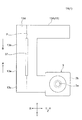
- a portion D of the driving device 2 along the outer periphery of the fixed body 9 and between the movable body-side fixed portion 15 and the fixed body-side fixed portion 17 has a thickness direction T of the FPC 13 perpendicular to the direction Z of the optical axis L. It is an area that is routed in a posture of X and Y directions.
- the FPC 13 when viewed from the FPC 13 side of the optical unit 1, the FPC 13 is a region C along the outer periphery of the fixed body 9 and is routed to the portion D between the fixed portions 15 and 17, and the FPC 13 is The portion existing in the portion D between the portions 15 and 17 is a structure 23 that allows the movable body 7 to rotate around the optical axis L. Since the rotation permissible structure 23 of the FPC 13 is provided outside the fixed body 9 instead of inside the fixed body 9, it is easy to retrofit the optical module 3 having the FPC 13 to the movable body 7. ing.
- the drive device 2 and the optical unit 1 according to the embodiment of the present invention are relatively small devices or units used as a thin camera mounted on a camera-equipped mobile phone, a tablet PC, or the like.
- the drive unit 2 and the optical unit 1 include a support portion 11 that enables the optical module 3 to move in a rolling direction (shake around the optical axis L) direction R, and an actuator that corrects the shake of the optical module 3 in the rolling direction R. And, basically has.
- the optical module 3 according to the present embodiment has the movement in the pitching (vertical vibration) direction Y and the yawing (lateral vibration) direction X of the optical module 3 provided in this type of apparatus and unit.
- the optical module 3 may include a support structure (not shown) that enables the optical module 3 and an actuator that performs shake correction in the pitching direction Y and the yawing direction X of the optical module 3.
- the optical module 3 is a module that includes a lens 3a on the subject side + Z and incorporates an optical device for taking an image inside a rectangular housing 3b as an example.
- the optical module 3 is supported by a rectangular frame-shaped holder frame 8 provided as an example and provided so as to surround the remaining four surfaces excluding the front surface on which the lens 3a of the optical module 3 is provided and the rear surface on the opposite side.
- a pair of magnets 33 for rolling detection are attached to the outer surfaces of the holder frame 8 using two opposing surfaces of the holder frame 8.
- the rear surface of the optical module 3 is disposed so that one end of the FPC 13 faces, and the FPC 13 is drawn out so as to pass through the region C along the outer periphery of the fixed body 9 described above.
- the other end of the FPC 13 is attached to the fixed body 9 side.
- the movable frame 7 includes the optical module 3 and the holder frame 8 including the magnet 33 that moves in the rolling direction R together with one end of the FPC 13.
- the fixed body 9 has a window portion 41 on the + Z side of the subject, and has a rectangular container-shaped outer casing 39 as an example, which is slightly larger than the movable body 7 whose -Z side opposite to the subject is open. And a back plate 40 that covers an area of the outer periphery of the optical module 3 on the ⁇ Z side opposite to the open subject, excluding the drawing start end of the FPC 13.
- a coil mounting frame 35 is integrally provided inside the outer casing 39.
- a pair of the coil mounting frame 35 is provided at a position opposed to the set of magnets 33 for correcting the rolling detection.
- the coil 31 a pattern substrate in which a coil is taken in a wiring substrate as a pattern is employed as an example.
- leaf spring-like elastic members 12 are provided at four corners of the holder frame 8 of the movable body 7 and at four corners of the coil mounting frame 35 of the fixed body 9 opposed thereto.
- the support portion 11 that supports the movable body 7 in a movable state in the rolling direction R is configured.
- a mechanism for detecting the movement of the optical module 3 in the yawing direction X and the pitching direction Y and detecting and correcting the movement amount is configured as follows (not shown).
- the optical module 3 There is a two-axis correction actuator inside the optical module 3, and its structure is a mechanism different from the gimbal mechanism and has a mechanism for shifting the lens barrel in a direction perpendicular to the optical axis, and detects the shift amount of the lens barrel. It is driven by two sets of coils and magnets.
- the portion D of the FPC 13A between the movable-body-side fixed portion 15 and the fixed-body-side fixed portion 17 has the thickness direction T of the FPC 13A set in the directions X and Y orthogonal to the direction Z of the optical axis L. It is configured to be routed by. Incidentally, with such a configuration, the FPC 13A can be smoothly moved, and the rotation permitting structure 23 is simple and compact.
- the FPC 13A is disposed so as to be located inside (in the range of E) the region E occupied by the fixed body 9 and the movable body 7 in the optical axis direction Z. Further, in the present embodiment, the FPC 13A is configured to be located inside the region F occupied by the fixed body 9 in the optical axis direction Z. Incidentally, with such a configuration, it is possible to provide the driving device 2 and the optical unit 1A that are small in the height H in the optical axis direction Z and are compact in the optical axis direction Z suitable for a thin camera or the like.
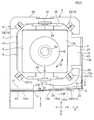
- the fixed body side fixing portion 17 is provided on the outer casing 39 of the fixed body 9 near the left end of the lower side 25 in FIG.
- a predetermined amount J is formed on the outer side of the rectangular shape.
- a swing permissible space 29 that allows the FPC 13A to swing with the movement of the optical module 3 in the rolling direction R is formed on the right side of the fixed body side fixing portion 17 in FIG. Becomes possible.
- “swing” is used to mean the movement or deformation of the FPC 13A accompanying the movement of the optical module 3 in the rolling direction R.
- the FPC 13A moves and deforms, that is, swings, with the position fixed to the fixed body side fixing portion 17 as a fulcrum O.
- the protrusion amount J of the fixed body-side fixing portion 17 is set based on the displacement amount of the optical module 3 in the rolling direction R and the like.
- the movable body-side fixing portion 15 is provided at the center in the Y direction of the side surface 26 (the right side with respect to the lower side 25) of the holder frame 8 of the movable body 7 in FIG.
- the position of the side surface 27 of the movable body side fixing portion 15 further protrudes outward in the radial direction G, and protrudes by a predetermined amount K from the side surface 26 of the fixed body 9 adjacent to the movable body side fixing portion 15 in FIG. Is configured.
- the movable body side fixing portion 15 is also configured by a rectangular convex portion as an example, similarly to the fixed body side fixing portion 17.
- the FPC 13A pulled out from the movable body side fixing portion 15 is separated from the outer peripheral surface of the outer casing 39 of the opposed fixed body 9 by the projection amount K, so that the movement of the optical module 3 in the rolling direction R When the FPC 13A moves with this, it is possible to reduce the possibility that the FPC 13A rubs against the outer peripheral surface of the outer casing 39.
- the direction of the fixed surface of the movable body-side fixed portion 15 is set in the first direction A
- the direction of the fixed surface of the fixed body-side fixed portion 17 is set in the second direction B.
- the first direction A and the second direction B are set to different directions orthogonal to each other.
- the FPC 13A includes a portion 13a extending from the movable body-side fixing portion 15 in the first direction A and a portion 13b extending from the fixed body-side fixing portion 17 in a second direction B different from the first direction A.
- a portion 13a of the FPC 13A extending in the first direction A and a portion 13b of the FPC 13A extending in the second direction B are arranged in an L-shape.
- the possibility that unnecessary reaction force acts on the movable body 7 from the rotation permitting structure 23 can be reduced, and the structure of the rotation permitting structure 23 can be simplified. Can be configured.
- the length M of the portion 13b of the FPC 13A extending in the second direction B on the fixed body side fixing portion 17 side is set to the length of the portion 13a of the FPC 13A extending in the first direction A on the movable body side fixing portion 15 side. It is set to be longer than N.
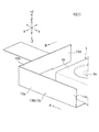
- the developed shape of the used FPC 13A is formed in a U-shape in plan view as shown in FIG.
- the middle part of the FPC 13A is formed to be somewhat wider than other parts.
- the intermediate portion of the FPC 13A formed wide is a portion that fits into a portion D between the movable body-side fixed portion 15 and the fixed body-side fixed portion 17 of the FPC 13A, and this portion is folded in the optical axis direction Z to form two portions.
- the above configuration is such that the height dimension H in the optical axis direction Z falls within the range of the regions E and F occupied in the axial direction Z.
- the center in the longitudinal direction of the intermediate portion of the FPC 13A folded in the optical axis direction Z is a folding line P as an example, and a slit 37 for facilitating the folding of the FPC 13A on the folding line P.
- the slit 37 also has an effect of suppressing local swelling of the folded portion of the FPC 13A.
- both the portion 13c fixed to the movable body-side fixing portion 15 of the FPC 13A and the portion 13d fixed to the fixed body-side fixing portion 17 of the FPC 13A have a rectangular flat plate-like reinforcing plate 43 as an example. Is provided.
- the reinforcing plate 43 is provided as an example between the two fixing portions 15 and 17 and the portions 13c and 13d of the FPC 13A fixed to the two fixing portions 15 and 17.
- the reinforcing plate 43 is preferably integrated with the FPC 13A in advance and attached thereto. Further, the reinforcing plate 43 is preferably formed of a material having excellent heat resistance in addition to mechanical strength. For example, by selecting a material having a thermal expansion coefficient close to the material of the two fixing portions 15 and 17 as the material of the reinforcing plate 43, the fear of peeling of the FPC 13A due to a thermal change can be reduced. Further, the reinforcing plate 43 can be disposed outside the FPC 13A, that is, on the side opposite to the fixing portions 15 and 17 with respect to the FPC 13A, and is disposed while being sandwiched in the multi-folded FPC 13A. It is also possible. That is, the reinforcing plate 43 includes a case where the reinforcing plate 43 comes to the outermost peripheral side of the FPC 13A and a case where it comes between the folded FPCs 13A.
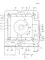
- the displacement of the rolling detection magnet 33 appears as a change in the relative position with respect to the set of rolling detection coils 31 attached to the coil mounting frame 35, and the amount of change in the magnetic flux density generated by the change in the relative position. Is detected by a magnetic sensor (not shown) or the like, and the shake of the optical module 3 in the rolling direction R is corrected based on the detected amount. After the shake correction in the rolling direction R, the supply of the current to the drive source is stopped, and the elastic member 12 returns to the original state due to the elasticity of the elastic member 12.
- the FPC 13A held by the fixing portions 15, 17 also moves while changing its shape in accordance with the rotation amount and the rotation direction.
- the portion 13a of the FPC 13A extending in the first direction A moves substantially linearly along the first direction A.
- the portion 13b of the FPC 13A extending in the second direction B is defined as a connection point Q with the portion 13a extending in the first direction A with the portion fixed to the fixed side fixing portion 17 as a fulcrum O. It swings so as to move in a direction substantially along A. Then, at this time, the FPC 13A moves smoothly without generating a reaction force that affects the movement of the optical module 3, so that accurate shake correction of the optical module 3 can be performed.
- the driving device 2 and the optical unit 1A configured as described above, since the FPC 13A is routed along the outer periphery of the fixed body 9, the optical module 3 having the FPC 13A is connected to the driving device. 2 can be easily performed as a post-installation operation.
- a compact optical unit 1A can be provided in the optical axis direction Z and the directions X and Y orthogonal to the optical axis L, and the FPC 13A which does not affect the movement of the optical module 3 can be provided. The arrangement becomes possible.
- a flexible wiring board (FPC) 13B whose intermediate portion is narrower than the FPC 13A shown in FIG. .
- the width dimension of the intermediate portion of the FPC 13B is equal to or less than the height dimension of the region E occupied in the optical axis direction Z of the fixed body 9 and the movable body 7, and is more preferably in the optical axis direction of the fixed body 9.
- the height is set to be equal to or less than the height of the region F occupying Z.
- the FPC 13B is configured so as to be drawn around while maintaining one thickness without being folded in the middle, and is provided in the FPC 13A according to the first embodiment.
- the slit 37 was not provided.
- the thickness of the FPC 13B is desirably 0.1 mm or less. With such a setting, the FPC 13B that follows the movement of the optical module 3 in the rolling direction R can be smoothly moved or deformed.
- the optical unit 1B according to the present embodiment configured as described above can exhibit the same operation and effect as those of the first embodiment, facilitating assembly work by retrofitting the FPC 13B, and reducing the size of the optical unit 1B. Thus, the FPC 13B can be routed without affecting the optical module 3.
- the flexible printed circuit (FPC) 13 ⁇ / b> C has an intermediate portion around the optical axis L in the portion D between the movable body-side fixed portion 15 and the fixed body-side fixed portion 17. Curved along the direction.
- the entire intermediate portion of the FPC 13C may be curved, or only a part (eg, a corner) of the intermediate portion of the FPC 13C may be curved.
- the optical unit 1C according to the present embodiment configured as described above can exhibit the same operation and effect as the first embodiment, facilitating the assembling work by retrofitting the FPC 13C, and reducing the size of the optical unit 1C.
- the FPC 13C that does not affect the optical module 3 can be routed.
- the thickness of the FPC 13C increases, it is expected that the repulsive force due to the bending of the bending portion will affect the movement of the optical module 3 in the rolling direction R. Therefore, it is preferable to use the FPC 13C having a thickness as small as possible to reduce the influence of the repulsive force.
- the drive device 2 and the optical unit 1 according to the embodiment of the present invention are basically configured as described above, but a partial configuration change is made without departing from the gist of the present invention. Of course, it is also possible to perform omission or the like.
- the portion 13a of the flexible printed circuit (FPC) 13D extending in the first direction A and the portion 13b of the FPC 13D extending in the second direction B have an angle of 90 ° or more as shown in FIG.
- the rotation permissible structure 23 which is connected in a state of being crossed by ⁇ .
- the FPC 13D swings in a range indicated by a virtual line in FIG. 10 following the movement of the optical module 3 in the rolling direction R. .
- the virtual line 13D1 indicates the position of the FPC 13D when the optical module 3 rotates counterclockwise
- the virtual line 13D2 indicates the position of the FPC 13D when the optical module 3 rotates clockwise. Therefore, the amount of projection of the FPC 13D outward in the radial direction G (the imaginary line 13D2) is particularly small, so that this configuration is effective when the clearance with the camera housing on which the optical unit 1 is mounted is small.
- a bellows-like bent portion 45 is provided in a part of an intermediate portion of the flexible printed circuit (FPC) 13E, for example, a portion of the portion 13a extending in the first direction A to form a rotation permitting structure 23. It is possible. When such a configuration is employed, the swing of the portion 13b extending in the second direction B and the expansion and contraction of the bent portion 45 do not affect the optical module 3 by the reaction force of the FPC 13E. Smooth movement or deformation becomes possible.
- the number of times when the intermediate portion of the flexible printed circuit (FPC) 13 is folded back is not limited to two, but may be three or more as long as the FPC 13 can be smoothly moved or deformed.
- the layer structure applied to the flexible wiring board (FPC) 13 Either one side or both sides may be used, but even in that case, the thickness of the flexible wiring board (FPC) 13 is desirably set to 0.1 mm or less in order to ensure smooth movement of the flexible wiring board (FPC) 13.
- the shape of the corner portion of the outer casing 39 of the fixing body 9 in the portion D between the fixing portions 15 and 17 has a smooth curved shape in order to enable the smooth movement of the flexible wiring board (FPC) 13. It is desirable to form.
- SYMBOLS 1 Optical unit, 2 ... Drive device, 3 ... Optical module, 3a ... Lens, # 3b ... Housing, 5 ... Mounting part, 7 ... Movable body, 8 ... Holder frame, 9 ... Fixed body, # 11 ... Support part, 12 ...
Landscapes
- Physics & Mathematics (AREA)
- General Physics & Mathematics (AREA)
- Optics & Photonics (AREA)
- Engineering & Computer Science (AREA)
- Multimedia (AREA)
- Signal Processing (AREA)
- Adjustment Of Camera Lenses (AREA)
- Studio Devices (AREA)
- Lens Barrels (AREA)
Priority Applications (2)
| Application Number | Priority Date | Filing Date | Title |
|---|---|---|---|
| US17/265,511 US12117722B2 (en) | 2018-08-09 | 2019-07-05 | Drive device and optical unit |
| CN201980052355.6A CN112543888B (zh) | 2018-08-09 | 2019-07-05 | 驱动装置及光学单元 |
Applications Claiming Priority (2)
| Application Number | Priority Date | Filing Date | Title |
|---|---|---|---|
| JP2018-150630 | 2018-08-09 | ||
| JP2018150630A JP7085940B2 (ja) | 2018-08-09 | 2018-08-09 | 駆動装置及び光学ユニット |
Publications (1)
| Publication Number | Publication Date |
|---|---|
| WO2020031577A1 true WO2020031577A1 (ja) | 2020-02-13 |
Family
ID=69415467
Family Applications (1)
| Application Number | Title | Priority Date | Filing Date |
|---|---|---|---|
| PCT/JP2019/026756 Ceased WO2020031577A1 (ja) | 2018-08-09 | 2019-07-05 | 駆動装置及び光学ユニット |
Country Status (4)
| Country | Link |
|---|---|
| US (1) | US12117722B2 (https=) |
| JP (1) | JP7085940B2 (https=) |
| CN (1) | CN112543888B (https=) |
| WO (1) | WO2020031577A1 (https=) |
Families Citing this family (12)
| Publication number | Priority date | Publication date | Assignee | Title |
|---|---|---|---|---|
| JP2022056747A (ja) * | 2020-09-30 | 2022-04-11 | 日本電産サンキョー株式会社 | 光学ユニット |
| US12474539B2 (en) | 2021-02-09 | 2025-11-18 | Nidec Sankyo Corporation | Optical unit |
| JP7611057B2 (ja) * | 2021-02-09 | 2025-01-09 | ニデックインスツルメンツ株式会社 | 光学ユニット |
| JP2022130183A (ja) | 2021-02-25 | 2022-09-06 | 日本電産株式会社 | 揺れ補正ユニット、光学ユニットおよびスマートフォン |
| JP7671640B2 (ja) * | 2021-03-31 | 2025-05-02 | ニデックインスツルメンツ株式会社 | 振れ補正機能付き光学ユニット |
| US11917296B2 (en) | 2021-05-25 | 2024-02-27 | Nidec Corporation | Wiring member, shake correction unit, and smartphone |
| JP2022181060A (ja) * | 2021-05-25 | 2022-12-07 | 日本電産株式会社 | 配線部材、揺れ補正ユニットおよびスマートフォン |
| JP2023051397A (ja) | 2021-09-30 | 2023-04-11 | 日本電産株式会社 | 回路基板および光学ユニット |
| JP7812226B2 (ja) * | 2021-12-28 | 2026-02-09 | ニデックインスツルメンツ株式会社 | 振れ補正機能付き光学ユニット |
| JP7749456B2 (ja) * | 2021-12-28 | 2025-10-06 | ニデックインスツルメンツ株式会社 | 振れ補正機能付き光学ユニット |
| JP2024008168A (ja) | 2022-07-07 | 2024-01-19 | ニデックインスツルメンツ株式会社 | 振れ補正機能付き光学ユニット |
| JP2024115071A (ja) * | 2023-02-14 | 2024-08-26 | パナソニックIpマネジメント株式会社 | レンズユニットおよびこれを備えたレンズ鏡筒 |
Citations (5)
| Publication number | Priority date | Publication date | Assignee | Title |
|---|---|---|---|---|
| JP2007197528A (ja) * | 2006-01-25 | 2007-08-09 | Toyobo Co Ltd | ペースト、フレキシブルプリント配線板の補強板及びその製造方法 |
| JP2013251499A (ja) * | 2012-06-04 | 2013-12-12 | Nec Access Technica Ltd | 立体構造フレキシブルプリント配線基板およびループ配線形成方法 |
| JP2016126138A (ja) * | 2014-12-26 | 2016-07-11 | 株式会社ニコン | 振れ補正装置、レンズ鏡筒、光学装置 |
| JP2017215550A (ja) * | 2016-06-02 | 2017-12-07 | 日本電産サンキョー株式会社 | 振れ補正機能付き光学ユニット |
| JP2018077395A (ja) * | 2016-11-10 | 2018-05-17 | 日本電産サンキョー株式会社 | 振れ補正機能付き光学ユニット |
Family Cites Families (7)
| Publication number | Priority date | Publication date | Assignee | Title |
|---|---|---|---|---|
| JP2002344784A (ja) | 2001-05-18 | 2002-11-29 | Sony Corp | ビデオカメラ装置 |
| KR100531878B1 (ko) * | 2003-07-08 | 2005-11-29 | 엘지전자 주식회사 | 휴대용 단말기의 회전형 카메라 장치 |
| WO2012004994A1 (ja) | 2010-07-07 | 2012-01-12 | パナソニック株式会社 | カメラ駆動装置 |
| JP5771373B2 (ja) * | 2010-08-06 | 2015-08-26 | 日本電産サンキョー株式会社 | 振れ補正機能付き光学ユニット |
| JP5556543B2 (ja) * | 2010-09-30 | 2014-07-23 | ティアック株式会社 | カメラモジュール取り付け装置 |
| JP6284742B2 (ja) | 2013-10-24 | 2018-02-28 | 日本電産サンキョー株式会社 | 振れ補正機能付き光学ユニット |
| JP6460809B2 (ja) | 2015-01-26 | 2019-01-30 | 日本電産サンキョー株式会社 | 振れ補正機能付き光学ユニット |
-
2018
- 2018-08-09 JP JP2018150630A patent/JP7085940B2/ja active Active
-
2019
- 2019-07-05 CN CN201980052355.6A patent/CN112543888B/zh active Active
- 2019-07-05 US US17/265,511 patent/US12117722B2/en active Active
- 2019-07-05 WO PCT/JP2019/026756 patent/WO2020031577A1/ja not_active Ceased
Patent Citations (5)
| Publication number | Priority date | Publication date | Assignee | Title |
|---|---|---|---|---|
| JP2007197528A (ja) * | 2006-01-25 | 2007-08-09 | Toyobo Co Ltd | ペースト、フレキシブルプリント配線板の補強板及びその製造方法 |
| JP2013251499A (ja) * | 2012-06-04 | 2013-12-12 | Nec Access Technica Ltd | 立体構造フレキシブルプリント配線基板およびループ配線形成方法 |
| JP2016126138A (ja) * | 2014-12-26 | 2016-07-11 | 株式会社ニコン | 振れ補正装置、レンズ鏡筒、光学装置 |
| JP2017215550A (ja) * | 2016-06-02 | 2017-12-07 | 日本電産サンキョー株式会社 | 振れ補正機能付き光学ユニット |
| JP2018077395A (ja) * | 2016-11-10 | 2018-05-17 | 日本電産サンキョー株式会社 | 振れ補正機能付き光学ユニット |
Also Published As
| Publication number | Publication date |
|---|---|
| JP7085940B2 (ja) | 2022-06-17 |
| JP2020027134A (ja) | 2020-02-20 |
| CN112543888A (zh) | 2021-03-23 |
| US20210223661A1 (en) | 2021-07-22 |
| US12117722B2 (en) | 2024-10-15 |
| CN112543888B (zh) | 2022-05-10 |
Similar Documents
| Publication | Publication Date | Title |
|---|---|---|
| WO2020031577A1 (ja) | 駆動装置及び光学ユニット | |
| JP7057210B2 (ja) | 光学ユニット | |
| EP2259571B1 (en) | Optical image stabilizer for camera lens module | |
| JP5769712B2 (ja) | 傾き補正ユニット | |
| CN112513733B (zh) | 光学单元 | |
| CN108693677A (zh) | 带抖动修正功能的光学单元 | |
| JP7143034B2 (ja) | 手振れ補正装置、カメラ装置及び電子機器 | |
| JP2020027134A5 (https=) | ||
| CN113168072A (zh) | 光学单元 | |
| TWI587070B (zh) | 攝像模組 | |
| JP2015210316A (ja) | 像ブレ補正装置および撮像装置 | |
| JP2021039159A (ja) | 光学ユニット | |
| CN114911111B (zh) | 光学单元 | |
| JP2007047652A (ja) | 光学機器 | |
| JP7611057B2 (ja) | 光学ユニット | |
| JP7481984B2 (ja) | 光学ユニット | |
| CN115220281B (zh) | 光学单元 | |
| JP7686495B2 (ja) | 振れ補正機能付き光学ユニット | |
| JP7749456B2 (ja) | 振れ補正機能付き光学ユニット | |
| JP7716926B2 (ja) | 光学ユニット | |
| JP7172856B2 (ja) | 駆動装置 | |
| JP7120851B2 (ja) | レンズ羽根駆動装置 | |
| CN117641101A (zh) | 带抖动修正功能的光学单元 | |
| JP2023075466A (ja) | 振れ補正機能付き光学ユニット | |
| JP4324744B2 (ja) | 撮像素子のステージ構造及び撮像装置 |
Legal Events
| Date | Code | Title | Description |
|---|---|---|---|
| 121 | Ep: the epo has been informed by wipo that ep was designated in this application |
Ref document number: 19848421 Country of ref document: EP Kind code of ref document: A1 |
|
| NENP | Non-entry into the national phase |
Ref country code: DE |
|
| 122 | Ep: pct application non-entry in european phase |
Ref document number: 19848421 Country of ref document: EP Kind code of ref document: A1 |