WO2020031518A1 - 流量計測装置 - Google Patents
流量計測装置 Download PDFInfo
- Publication number
- WO2020031518A1 WO2020031518A1 PCT/JP2019/024444 JP2019024444W WO2020031518A1 WO 2020031518 A1 WO2020031518 A1 WO 2020031518A1 JP 2019024444 W JP2019024444 W JP 2019024444W WO 2020031518 A1 WO2020031518 A1 WO 2020031518A1
- Authority
- WO
- WIPO (PCT)
- Prior art keywords
- flow
- measurement device
- flow path
- insertion direction
- protrusion
- Prior art date
Links
Images


Classifications
-
- G—PHYSICS
- G01—MEASURING; TESTING
- G01F—MEASURING VOLUME, VOLUME FLOW, MASS FLOW OR LIQUID LEVEL; METERING BY VOLUME
- G01F5/00—Measuring a proportion of the volume flow
-
- F—MECHANICAL ENGINEERING; LIGHTING; HEATING; WEAPONS; BLASTING
- F02—COMBUSTION ENGINES; HOT-GAS OR COMBUSTION-PRODUCT ENGINE PLANTS
- F02D—CONTROLLING COMBUSTION ENGINES
- F02D41/00—Electrical control of supply of combustible mixture or its constituents
- F02D41/02—Circuit arrangements for generating control signals
- F02D41/18—Circuit arrangements for generating control signals by measuring intake air flow
-
- F—MECHANICAL ENGINEERING; LIGHTING; HEATING; WEAPONS; BLASTING
- F02—COMBUSTION ENGINES; HOT-GAS OR COMBUSTION-PRODUCT ENGINE PLANTS
- F02M—SUPPLYING COMBUSTION ENGINES IN GENERAL WITH COMBUSTIBLE MIXTURES OR CONSTITUENTS THEREOF
- F02M35/00—Combustion-air cleaners, air intakes, intake silencers, or induction systems specially adapted for, or arranged on, internal-combustion engines
- F02M35/02—Air cleaners
- F02M35/0201—Housings; Casings; Frame constructions; Lids; Manufacturing or assembling thereof
- F02M35/021—Arrangements of air flow meters in or on air cleaner housings
-
- F—MECHANICAL ENGINEERING; LIGHTING; HEATING; WEAPONS; BLASTING
- F02—COMBUSTION ENGINES; HOT-GAS OR COMBUSTION-PRODUCT ENGINE PLANTS
- F02M—SUPPLYING COMBUSTION ENGINES IN GENERAL WITH COMBUSTIBLE MIXTURES OR CONSTITUENTS THEREOF
- F02M35/00—Combustion-air cleaners, air intakes, intake silencers, or induction systems specially adapted for, or arranged on, internal-combustion engines
- F02M35/10—Air intakes; Induction systems
- F02M35/10373—Sensors for intake systems
- F02M35/10386—Sensors for intake systems for flow rate
-
- G—PHYSICS
- G01—MEASURING; TESTING
- G01F—MEASURING VOLUME, VOLUME FLOW, MASS FLOW OR LIQUID LEVEL; METERING BY VOLUME
- G01F1/00—Measuring the volume flow or mass flow of fluid or fluent solid material wherein the fluid passes through a meter in a continuous flow
- G01F1/68—Measuring the volume flow or mass flow of fluid or fluent solid material wherein the fluid passes through a meter in a continuous flow by using thermal effects
- G01F1/684—Structural arrangements; Mounting of elements, e.g. in relation to fluid flow
- G01F1/6842—Structural arrangements; Mounting of elements, e.g. in relation to fluid flow with means for influencing the fluid flow
-
- G—PHYSICS
- G01—MEASURING; TESTING
- G01F—MEASURING VOLUME, VOLUME FLOW, MASS FLOW OR LIQUID LEVEL; METERING BY VOLUME
- G01F1/00—Measuring the volume flow or mass flow of fluid or fluent solid material wherein the fluid passes through a meter in a continuous flow
- G01F1/72—Devices for measuring pulsing fluid flows
Definitions
- the present disclosure relates to a flow measurement device.
- a flow measurement device that is a thermal flow meter that includes a housing disposed in a main flow path and a sub flow path provided in the housing and measures the flow rate of a fluid to be measured flowing through the main flow path is known (for example, Patent Document 1).
- This flow rate measuring device has a tip wing provided at a position deviated downstream on the tip of the housing.
- the tip wing has a shape that tapers as it moves from the base end to the tip.
- a lateral vortex may be generated around the inlet of the sub flow path.
- the fluid to be measured may flow into the sub-flow path due to the lateral vortex and may be measured as an intake air amount. For this reason, an error may occur in the measured flow rate.
- a flow rate measurement device that is attached to the main flow path while being inserted from the outside of a main flow path through which a measurement target fluid flows, and measures a flow rate of the measurement target fluid in the main flow path. Is done.
- the flow rate measuring device includes a housing having a side surface extending along a direction in which the flow rate measuring device is inserted into the main flow path and a tip end surface located on the insertion direction side, and the main flow path formed inside the housing, A sub flow path through which a part of the fluid to be detected flows, and an inlet portion provided on the side surface to allow the measured fluid flowing through the main flow path to flow into the sub flow path; and the sub flow path.
- a protruding portion is disposed on at least one end of the distal end surface, which is an end on the entrance portion side, and the other end, which is an end opposite to the one end. Have been.
- the protruding portion is disposed at least on one end of the front end surface, which is the end on the inlet side, and on the other end, which is the end opposite to the one end.
- the flow rate measuring device is used in a case where the measured fluid flowing in the main flow channel flows in any one of the forward flow direction and the reverse flow direction when the inlet portion is attached so as to face the upstream side of the main flow channel. Even if it does, the separation of the intake air occurs at the protruding portion located further distally than the distal end surface. This makes it possible to increase the distance between the position where the lateral vortex is generated due to separation and the entrance, as compared with the case where the protrusion is not provided. Therefore, regardless of whether the flow of the fluid to be measured is a forward flow or a backward flow, the flow measurement device can reduce the measurement error of the flow due to the influence of the lateral vortex.
- FIG. 1 is a schematic diagram of a combustion system in which the flow measurement device according to the embodiment is used
- FIG. 2 is a schematic side view of the flow measurement device according to the embodiment
- FIG. 3 is a schematic top view of the flow measurement device according to the embodiment
- FIG. 4 is a schematic cross-sectional view of a main flow path around the flow measurement device according to the embodiment
- FIG. 5 is a schematic cross-sectional view of the flow measurement device according to the embodiment
- FIG. 6 is a schematic diagram when the attached state of the flow rate measuring device according to the embodiment is viewed from the inlet side
- FIG. 1 is a schematic diagram of a combustion system in which the flow measurement device according to the embodiment is used
- FIG. 2 is a schematic side view of the flow measurement device according to the embodiment
- FIG. 3 is a schematic top view of the flow measurement device according to the embodiment
- FIG. 4 is a schematic cross-sectional view of a main flow path around the flow measurement device according to the embodiment
- FIG. 5 is a schematic
- FIG. 7 is a schematic diagram when the mounting state of the flow measurement device according to the embodiment is viewed from the base end side in the insertion direction
- FIG. 8 is a schematic diagram of the flow measuring device according to the embodiment when viewed from the front end side
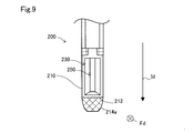
- FIG. 9 is a first schematic diagram of the flow measurement device according to the first other embodiment when viewed from the inlet side
- FIG. 10 is a second schematic diagram when the flow measurement device according to the first other embodiment is viewed from the inlet side
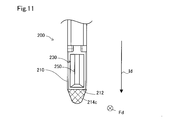
- FIG. 11 is a third schematic diagram when the flow measurement device according to the first other embodiment is viewed from the inlet side
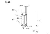
- FIG. 12 is a fourth schematic diagram when the flow measurement device according to the first other embodiment is viewed from the inlet side.
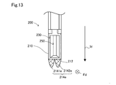
- FIG. 13 is a fifth schematic diagram when the flow measurement device according to the first other embodiment is viewed from the inlet side.
- FIG. 14 is a sixth schematic diagram when the flow measurement device according to the first other embodiment is viewed from the inlet side.
- FIG. 15 is a seventh schematic diagram when the flow measurement device according to the first other embodiment is viewed from the inlet side.
- FIG. 16 is an eighth schematic diagram when the flow measurement device according to the first other embodiment is viewed from the inlet side.
- FIG. 17 is a ninth schematic diagram when the flow measurement device according to the first other embodiment is viewed from the inlet side.
- FIG. 18 is a first schematic diagram of the flow measurement device according to the first other embodiment when viewed from the side.
- FIG. 19 is a second schematic diagram of the flow measuring device according to the first other embodiment when viewed from the side
- FIG. 20 is a third schematic diagram when the flow measurement device according to the first other embodiment is viewed from the side.
- FIG. 21 is a fourth schematic diagram when the flow measurement device according to the first other embodiment is viewed from the side.
- FIG. 22 is a fifth schematic diagram when the flow measurement device according to the first other embodiment is viewed from the side.
- FIG. 23 is a sixth schematic diagram when the flow measurement device according to the first other embodiment is viewed from the side.
- FIG. 24 is a seventh schematic diagram when the flow measuring device according to the first other embodiment is viewed from the side.
- FIG. 25 is an eighth schematic diagram when the flow measuring device according to the first other embodiment is viewed from the side.
- FIG. 26 is a ninth schematic diagram when the flow measurement device according to the first other embodiment is viewed from the side.
- FIG. 27 is a tenth schematic diagram when the flow measurement device according to the first other embodiment is viewed from the side.
- FIG. 28 is a first schematic diagram of the flow measuring device according to the first other embodiment when viewed from the distal end side
- FIG. 29 is a second schematic diagram when the flow measurement device according to the first other embodiment is viewed from the distal end side
- FIG. 30 is a third schematic diagram when the flow measurement device according to the first other embodiment is viewed from the distal end side
- FIG. 31 is a tenth schematic diagram when the flow measurement device according to the first other embodiment is viewed from the inlet side.
- FIG. 28 is a first schematic diagram of the flow measuring device according to the first other embodiment when viewed from the distal end side
- FIG. 29 is a second schematic diagram when the flow measurement device according to the first other embodiment is viewed from the distal end side
- FIG. 30 is a
- FIG. 32 is an eleventh schematic diagram when the flow measurement device according to the first other embodiment is viewed from the side.
- FIG. 33 is a first schematic diagram of a flow measuring device according to another second embodiment when viewed from the side.
- FIG. 34 is a second schematic diagram of the flow measuring device according to the second other embodiment when viewed from the side.
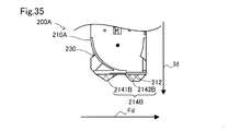
- FIG. 35 is a third schematic diagram of the flow measurement device according to the second other embodiment when viewed from the side.
- a flow measurement device 200 is used for a combustion system 10 including an internal combustion engine 11.
- the combustion system 10 includes an internal combustion engine 11, a main flow path 12 and an exhaust flow path 13 formed by piping, and an ECU 30.
- the combustion system 10 is mounted on, for example, a gasoline-powered vehicle and is used as a driving device.
- the internal combustion engine 11 includes a combustion chamber 110, a spark plug 111, a fuel injection valve 112, a combustion pressure sensor 114, an intake valve 125, and an exhaust valve 131.
- the internal combustion engine 11 generates power by burning a mixed gas of air supplied through the main flow path 12 and fuel injected from the fuel injection valve 112.
- the spark plug 111 generates a spark discharge and ignites a mixed gas (mixed gas of fuel and air) in the combustion chamber 110.
- the fuel injection valve 112 injects fuel into the combustion chamber 110.
- the combustion pressure sensor 114 detects the combustion pressure in the combustion chamber 110.
- the main passage 12 and the exhaust passage 13 are connected to the combustion chamber 110.
- the main flow path 12 is a flow path that guides air to the combustion chamber 110.
- the exhaust passage 13 is a passage for discharging exhaust gas, which is a gas after combustion, from the combustion chamber 110.
- the main flow path 12 is provided with an air cleaner 121, a flow rate measuring device 200, and a throttle valve 122 in order from the upstream side.
- the air cleaner 121 removes dust in the air flowing through the main flow path 12.
- the throttle valve 122 adjusts the opening degree and adjusts the flow resistance in the main flow path 12.
- the flow measurement device 200 measures the flow rate of the intake air flowing through the main flow path 12.
- the ECU 30 is an arithmetic processing circuit including a processor, a storage medium such as a RAM, a ROM, and a flash memory, a microcomputer including an input / output unit, and a power supply circuit.
- the ECU 30 controls the opening degree of the throttle valve 122 and the fuel injection amount injected from the fuel injection valve 112 using measurement results obtained from the flow measurement device 200 and various sensors, for example, the combustion pressure sensor 114.
- the flow measurement device 200 includes a housing 210, an inlet 230, an outlet 240, and an outlet 250.
- the housing 210 has a side surface extending along the insertion direction Id, and a distal end surface 212 located on the insertion direction Id side.
- the inlet 230 is provided on the one end 2122 side of the distal end surface 212 on the side of the opening Od of the inlet 230.
- the outlet 250 is provided on the other end 2124 side opposite to the one end 2122 side where the inlet 230 is provided.
- two outlet portions 240 are provided, and in addition to the outlet portions 240 provided on the side surface side shown in FIG. 2, they are provided on the opposite side surface.
- the two outlets 240 are respectively provided on surfaces of the side surfaces of the housing 210 that intersect with the surface on which the inlet 230 is provided.
- a projection 214 is provided on the distal end surface 212 and protrudes from the distal end surface 212 toward the insertion direction Id.
- the protruding portion 214 protrudes from the distal end surface 212 in the insertion direction Id from one end 2122 to the other end 2124.
- the protrusion 214 does not have an internal space for flowing the intake air.
- the appearance of the protrusion 214 is illustrated by cross hatching.
- the first length W1 from the lower end of the opening of the outlet 250 to the tip of the protrusion 214 in the insertion direction Id is 15% or more of the opening width W2 of the outlet 250 in the present embodiment. It protrudes from the distal end surface 212 so as to have a size.
- the opening width W2 is the maximum value of the width of the opening of the outlet 250 in the insertion direction Id.
- the second length W3 from the lower end of the opening of the entrance 230 to the tip of the projection 214 in the insertion direction Id is 15% or more of the opening width W4 of the entrance 230. Projecting from the front end surface 212.
- the opening width W3 is the maximum value of the width of the opening of the entrance 230 in the insertion direction Id.
- FIG. 4 shows a cross section of the flow measurement device 200 corresponding to the 4-4 cross section shown in FIG.
- the housing 210 is a housing made of a synthetic resin, and includes a sub-flow path forming section that forms the sub-flow path 220 therein, and a holding section that holds the flow rate detection section 260.
- One end 2122 provided with the inlet 230 is located on the upstream side of the main flow channel 12 when the flow measurement device 200 is attached to the main flow channel 12.
- the other end 2124 is located downstream from the one end 2122 when the flow measurement device 200 is attached to the main flow path 12.
- the sub flow path 220 is a flow path through which a part of the intake air flowing through the main flow path 12 flows.
- FIG. 5 which is a schematic view showing a cross section taken along line 5-5 in FIG. I have.
- Each of the branched sub-flow paths 220 is connected to two outlets 240.
- the flow rate detector 260 (FIG. 4) is provided in the middle of the sub flow path 220 and detects the flow rate of the fluid to be measured flowing through the sub flow path. It is preferable that the flow rate detector 260 can distinguish whether the flow direction of the fluid to be measured is the forward flow direction or the backward flow direction.
- the flow rate detection unit 260 employs a temperature difference method that is capable of distinguishing the flow direction.
- the flow rate detection unit 260 includes a heater (not shown) for heating the fluid to be measured, and a plurality of temperature sensors arranged along the flow direction of the fluid to be measured.
- the flow rate detection unit 260 of the present embodiment detects the flow rate from the temperature difference between the upstream side and the downstream side of the heater.
- the temperature sensors are arranged on both the upstream side and the downstream side of the heater.
- the temperature sensor is a temperature-sensitive resistor
- the heater is a heating resistor.
- the housing 210 has a housing main body 2100 that is inserted into the main flow channel 12 when attached to the main flow channel 12. Further, the housing 200 includes a ring holding portion 2101, a flange portion 2102, a connector portion 2103, a protection protrusion 2104, and a temperature sensor 2105 provided integrally with the housing main body 2100.
- the flange portion 2102 is provided on the base end side of the housing 210 and serves as a fixed portion to the main flow channel 12.
- Wiring for outputting a measurement result by the flow measurement device 200 to the outside is connected to the connector 2103.
- the ring holding unit 2101 is attached to the insertion hole 124 via the O-ring 126.
- Temperature sensor 2105 acquires the temperature of the intake air.
- a bolt insertion port 270 is formed in the flange portion 2102. A bolt inserted from the bolt insertion port 270 is fixed to a boss 125 provided in the main flow path 12.
- the flow measurement device 200 is attached so as to pass through the center of the main flow channel 12 when viewed from the inlet 230 side.
- the flow measurement device 200 is configured such that the opening direction Od of the inlet 230 for taking in the intake air flowing through the main flow path 12 into the flow measurement device 200 is opposite to the flow direction Fd of the inflow air. Attached to. That is, the inlet 230 is arranged so as to face the upstream side of the main flow path 12.
- a discharge port 250 can be seen on the inner side (+ FD direction side) of the inlet 230. As shown in FIG. 6, the outlet 250 is narrowed so that the opening is smaller than the opening of the inlet 230.
- the projection 214 has a tapered shape that becomes thinner toward the distal end in the insertion direction when viewed from the entrance 230 side.
- the size of the protrusion 214 decreases toward the distal end. Due to the tapered shape, the protruding portion 214 can reduce the resistance received from the intake air when disposed in the main flow path 12. Thereby, the intake air is rectified, and the flow of the intake air around the protrusion 214 is smoothed.
- the protrusion 214 in the present embodiment has an elliptical shape when viewed from the distal end side in the insertion direction Id.
- one end 2122 and the other end 2124 are round and have an elongated shape as a whole. For this reason, the protrusion 214 can reduce the resistance received from the intake air when disposed in the main flow path 12. Thus, the intake air is rectified, and the flow of the intake air around the protrusion 214 is further smoothed.
- the protrusion 214 is viewed from a direction orthogonal to the opening direction Od and the insertion direction Id of the inlet 230, that is, from the side surface on which one of the two outlets 240 is provided in the present embodiment.
- it has a tapered shape that becomes thinner toward the distal end side in the insertion direction Id.
- the protrusion 214 can reduce the resistance received from the intake air when the protrusion 214 is disposed in the main flow path 12. Thereby, the intake air is rectified, and the flow of the intake air around the protrusion 214 is smoothed.
- the protrusion 214 has a curved shape when viewed from the side.
- the flow measurement device 200 when the flow measurement device 200 is disposed in the main flow path 12, friction occurs between the intake air and the housing 210 of the flow measurement device 200, and thus the flow velocity of the intake air flowing around the flow measurement device 200 is , As it goes downstream of the flow. For this reason, the intake air cannot flow along the shape of the flow measurement device 200, and the separation of the intake air may occur. For example, in a forward flow state in which the intake air flows from the upstream side to the downstream side of the main flow path 12, separation may occur on the other end 2124 side. Further, for example, in a reverse flow state in which the intake air flows from the downstream side to the upstream side of the main flow path 12, separation may occur on the one end 2122 side.
- the lateral vortex is a vortex having a rotation axis that intersects a plane defined by the insertion direction Id and the flow direction Fd.
- the projecting portion 214 projects at the other end 2124 from the tip end surface 212 in the insertion direction Id, and rectifies the flow of intake air at the other end 2124. Therefore, in the forward flow state, the separation of the intake air from the flow measurement device 200 on the other end 2124 side is reduced as compared with the case where the protrusion 214 is not formed at the other end 2124. Thereby, the lateral vortex generated at the other end 2124 can be reduced.
- the upstream pressure at the one end 2122 at which the intake air separates tends to be smaller than the pressure in other regions.
- a side vortex having a rotation axis extending in a direction intersecting the insertion direction Id of the flow measurement device 200 is generated on the one end 2122 side.
- the discharge of the intake air flowing in from the outlet 250 from the inlet 230 is inhibited, and the intake air flowing from the outlet 250 is prevented. May flow into the sub flow path 220.
- a measurement error of the flow rate by the flow rate measurement device 200 may occur.
- the backflow state occurs, for example, when the idling operation is performed in the combustion system 10.
- the combustion system 10 stops the flow of the intake air into the internal combustion engine 11 by closing the intake valve 125.
- the pressure of the intake air on the internal passage 11 side of the main passage 12 increases, the pressure on the downstream side of the main passage 12 becomes higher than on the upstream side, and a backflow occurs.
- the protruding portion 214 protrudes from the distal end surface 212 at the one end 2122 in the insertion direction Id, and rectifies the flow of the intake air on the one end 2122 side. Therefore, in the backflow state, the separation of the intake air from the flow measurement device 200 on the one end 2122 side is reduced as compared with the case where the protrusion 214 is not formed at the other end 2124. Thereby, the lateral vortex generated at the one end 2122 can be reduced.
- the protrusion 214 has one end 2122 that is the end on the inlet side and the other end opposite to the one end 2122 in the front end surface 212. It protrudes from a certain other end 2124 in the insertion direction Id. Therefore, when the inlet portion 230 is attached to the main flow channel 12 so as to face the flow direction Fd of the main flow channel 12, the flow measuring device 200 causes the separation of the intake air to be located further distally than the distal end surface 212. It occurs at the protrusion 214. Accordingly, the distance between the position where the lateral vortex is generated and the inlet 230 or the outlet 250 can be made larger than when the protrusion 214 is not provided.
- the influence of the lateral vortex for example, the inhibition of the inflow of the intake air into the inlet 230 and the outlet 250 and the discharge of the intake air due to the lateral vortex are suppressed.
- the measurement error of the flow rate of the flow rate measuring device 200 due to the occurrence of the lateral vortex is reduced.
- the projecting portion 214 has a rectifying function which is a function of suppressing generation of a lateral vortex. Thereby, the measurement error of the flow rate of the flow rate measuring device 200 is further reduced.
- the protrusion 214 is provided from one end 2122 to the other end 2124.
- a horizontal vortex does not occur between the protrusion on the one end 2122 side and the protrusion on the other end 2124 which may occur in the case of a discontinuous structure. Therefore, the rectifying function is improved as compared with the case where the protruding portions 214 have a discontinuous structure at the one end 2122 side and the other end 2124 side.
- the projecting portion 214 has the front end surface 212 such that the first length W1 is 15% or more of the opening width W2 of the outlet 250. Projecting from. Therefore, it is easy to increase the distance between the discharge port 250 and the position where the lateral vortex is generated in the forward flow state.
- the projecting portion 214 projects from the distal end surface 212 such that the second length W3 is equal to or greater than 15% of the opening width W4 of the inlet 230. Therefore, it is easy to improve the effect of suppressing the influence of the lateral vortex in both the forward flow state and the backward flow state.
- Embodiment B Other Embodiment B1.
- the shape of the protruding portion 214 in the flow measurement device 200 according to the embodiment can be appropriately changed as long as it protrudes in at least one end 2122 and the other end 2124 in the insertion direction Id. .
- an example of the shape of the protruding portion 214 that can be employed will be described with reference to FIGS. 9 to 32.
- the protrusions 214a to 214d may be different from those in the above embodiment as long as the shape when viewed from the entrance 230 is tapered.
- the end on the insertion direction Id side has a planar shape.
- the protruding portion 214b shown in FIG. 10 has an end surface on the side of the insertion direction Id which has a flat shape as in the above example, and has a flat side surface and is inclined.
- the protruding portion 214c shown in FIG. 11 has a flat side surface and is inclined similarly to the protruding portion 214b shown in FIG.
- the end on the insertion direction Id side has a curved shape.
- the protruding portion 214d shown in FIG. 12 has a side surface inclined similarly to the protruding portions 214b and 214c shown in FIGS. 10 and 11, but has a sharp end on the insertion direction Id side.
- the flow measurement device 200 may have a plurality of protrusions 214e and 214f. In this case, as shown in FIG. 13, the plurality of protrusions 214 may be provided adjacent to each other in a direction orthogonal to the insertion direction Id and the opening direction Od. As shown in FIG.
- the plurality of protrusions 214 may be provided at a distance from each other in a direction orthogonal to the insertion direction Id and the opening direction Od.
- the plurality of protrusions 214g to 214i may have different shapes.
- one protrusion 2141g is formed by a curved surface.
- the other protrusion 2142g has a shape in which the side surface is inclined and the end on the insertion direction Id side is sharp.
- one of the protrusions 2141h has a flat side surface and is inclined, and an end on the insertion direction Id side has a flat shape.
- the other protrusion 2142h has a shape in which the side surface is inclined and the end on the insertion direction Id side is sharp.
- one protrusion 2141i is formed by a curved surface.
- the other protruding portion 2142i has a shape in which the side surface is inclined and the end on the insertion direction Id side is sharp.
- the protrusions 214j to 214p are shaped when viewed from a direction orthogonal to both the opening direction Od and the insertion direction Id of the inlet 230, that is, when viewed from the side.
- the protrusion 214j shown in FIG. 18 when viewed from the side, the one end 2122 side and the other end 2124 side are inclined toward the distal end in the insertion direction Id, and the end on the insertion direction Id side. Is a planar shape.
- the one end 2122 and the other end 2124 are inclined toward the tip end in the insertion direction Id, and the end on the insertion direction Id side.
- the part has a pointed shape.
- the one end 2122 and the other end 2124 when viewed from the side, have a curved shape, and the end in the insertion direction Id has a planar shape.
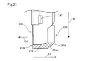
- the protrusion 214m shown in FIG. 21 when viewed from the side, the one end 2122 extends along the insertion direction Id, and the other end 2124 is inclined toward the front end in the insertion direction Id. I have.
- the end on the insertion direction Id side has a planar shape.
- the one end 2122 when viewed from the side, is inclined toward the distal end in the insertion direction Id, and the other end 2124 extends along the insertion direction Id. ing.
- the end on the insertion direction Id side has a planar shape.
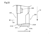
- the one end 2122 side when viewed from the side, has a curved surface shape, and the other end 2124 extends along the insertion direction Id.
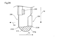
- the end of the protruding portion 214o on the insertion direction Id side has a planar shape. Further, for example, in the protrusion 214p shown in FIG. 24, when viewed from the side, the one end 2122 side and the other end 2124 side are inclined toward the distal end side in the insertion direction Id, and The ends are curved.
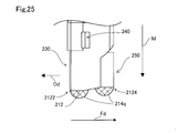
- the flow measurement device 200 may have a region where the protrusions 214q to 214s are not provided in a part between the one end 2122 and the other end 2124.
- the protrusion 214q shown in FIG. 25 has curved protrusions 2141q and 2142q on one end 2122 side and the other end 2124 side, respectively.
- the region between the one end 2122 and the other end 2124 does not have a region where the protrusions 214r and 214s are not provided, the one end 2122 and the other end 2124 respectively
- the protrusions 214r and 214s having different shapes may be provided. For example, in the protruding portion 214r shown in FIG.
- the protruding portion 2141r on the one end 2122 side is inclined at the one end 2122 side and the other end 2124 side, and the end on the insertion direction Id side has a planar shape.
- the protruding portion 2142r on the other end 2124 side has a shape in which the one end 2122 side and the other end 2124 side are inclined and the end on the insertion direction Id side is sharp.
- the protruding portion 2141s on the one end 2122 side is inclined on the one end 2122 side and the other end 2124 side, and the end on the insertion direction Id side has a planar shape.
- the protruding portion 2142s on the other end 2124 side has a curved shape.
- the shapes of the protrusions 214t to 214v when viewed from the direction opposite to the insertion direction Id, that is, when viewed from the distal end side may be different from those of the embodiment. .
- the protrusion 214t shown in FIG. 28 has a diamond shape when viewed from the front end side.
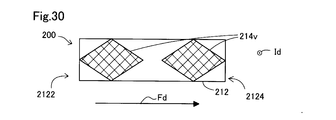
- the flow measuring device 200 may include a plurality of protrusions 214u and 214v. In this case, for example, as shown in FIGS. 29 and 30, the flow rate measuring device 200 may include two protrusions 214u and 214v arranged along the flow direction Fd. Specifically, for example, the protrusion 214u illustrated in FIG.
- the protrusion 29 has two protrusions 2141u and 2142u that are elliptical when viewed from the distal end side.
- the protrusion 214v illustrated in FIG. 30 has two protrusions 2141v and 2142v that are rhombic when viewed from the distal end side.
- the projection 214 has a tapered shape that becomes thinner toward the distal end in the insertion direction when viewed from the direction facing the entrance 230, but the shape of the projection 214 is It is not limited to this.
- the shape of the protrusion 214w may be a shape having a certain width in the insertion direction Id when viewed from the entrance 230 side.
- the protrusion 214 when viewed from the side, has a tapered shape that becomes thinner toward the distal end in the insertion direction Id.
- the shape of the protrusion 214 is not limited to this.
- the shape of the protrusion 214x may have a certain width in the insertion direction when viewed from the side.
- a flow measurement device 200A may include a housing 210A having a structure different from that of the embodiment.
- the flow measurement device 200 ⁇ / b> A may not have a branch flow path downstream of the sub flow path 220.
- the number of the outlet portion 240 may be one.
- the outlet 240 may be provided on a wall surface on the other end 2124 side.
- the flow measuring device 200A may have protrusions 214A and 214B of various shapes.
- the flow measurement device 200A may include a plurality of protrusions 214A and 214B. For example, as shown in FIG.
- the two protrusions 2141A and 2142A have side surfaces that are flat and inclined, and the ends on the insertion direction Id side have a flat shape.
- one of the protrusions 2141B of the two protrusions 214B has a flat side surface and is inclined, and the end on the insertion direction Id side has a pointed shape.
- the other protruding portion 2142B has a flat side surface and is inclined, and an end portion on the insertion direction Id side has a flat shape.
- the flow measurement device 200 is partially inserted into the main flow channel 12, but may be mounted in a state where the flow measurement device 200 is entirely inserted into the main flow channel 12. .
- the flow measurement device 200 may have a different flow path structure.
- the number of outlets 240 may be three or more.
- the number of the inlet portions 230 may be two or more.
- the flow measurement device 200 may not include the outlet 250.
- the flow measurement device 200 is used in the combustion system 10, but may be used in other than the combustion system 10.
- the flow measurement device 200 may be attached to an air supply pipe of an air supply system in a fuel cell system using air as an oxidant gas.
- the protrusion 214 projects from the distal end surface 212 such that the first length W1 is 15% or more of the opening width W2 of the outlet 250.
- the projecting portion 214 projects from the distal end surface 212 such that the second length W3 is 15% or more of the opening width W4 of the inlet 230.
- the size of the protrusion 214 is not limited to this.
- the protrusion 214 only needs to protrude from the distal end surface 212 to an extent that the influence of the lateral vortex can be suppressed in both the forward flow state and the backward flow state.
- the projecting portion 214 only needs to project, for example, so that the length W1 is equal to or more than 10% of the opening width W2 of the discharge port portion 250. Even in this case, the protrusion 214 can reduce the influence of the lateral vortex in the forward flow state as compared with the case where the first length W1 is less than 10% of the opening width W2.
- the projecting portion 214 only needs to project so that the second length W3 is equal to or greater than 10% of the opening width W4 of the entrance portion 230. Even in this case, the protrusion 214 can reduce the influence of the lateral vortex in the backflow state as compared with the case where the second length W3 is less than 10% of the opening width W4.
- the protruding portion 214 protrudes from the distal end surface 212 such that the first length W2 is equal to or greater than 15% of the opening width W3 of the discharge port portion 250. Further, it is preferable that the protruding portion 214 protrudes from the distal end surface 212 such that the second length W3 is 15% or more of the opening width W4.
- the present disclosure is not limited to the above-described embodiments, and can be implemented with various configurations without departing from the spirit thereof.
- the technical features in the present embodiment corresponding to the technical features in the respective embodiments described in the summary of the invention may be used to solve some or all of the above-described problems, or to achieve the above-described effects. In order to achieve some or all of them, replacements and combinations can be appropriately performed. Unless the technical features are described as essential in the present specification, they can be deleted as appropriate.
Abstract
流量測定装置(200)は、ハウジング(200)と、ハウジングの内部に形成され、主流路を流れる被検出流体の一部を流通させる副流路(220)と、側面に設けられ、主流路を流れる被計測流体を副流路内へと流入させる入口部と、出口部(240)と、流量検出部(260)と、先端面から挿入方向に突出した突出部(214)と、を備え、突出部は、先端面のうち少なくとも、入口部側の端部である一端部(2122)と、一端部とは反対側の端部である他端部(2124)と、に配置されている。
Description
本出願は、2018年8月8日に出願された日本出願番号2018-149045に基づくもので、ここにその記載内容を援用する。
本開示は、流量計測装置に関する。
主流路に配置されるハウジングと、ハウジングに設けられた副流路とを備え、主流路を流通する被計測流体の流量を計測する熱式流量計である流量計測装置が知られている(例えば特許文献1)。この流量計測装置は、ハウジング先端のうち下流側の偏位した位置に設けられた先端翼を有している。この先端翼は、基端から先端に移行するに従って先細りになる形状を有している。
従来の流量計測装置において、被計測流体の逆流が生じた場合には、副流路の入口周辺で横渦が発生する場合がある。入口周辺で横渦が発生した場合には、横渦によって被計測流体が、副流路に流入し、吸入空気量として計測されるおそれがある。このため、計測された流量に誤差が生じるおそれがある。
本開示は、以下の形態として実現することが可能である。
本開示の一形態によれば、被計測流体が流れる主流路の外部側から挿入された状態で前記主流路に取り付けられ、前記主流路における前記被計測流体の流量を測定する流量測定装置が提供される。この流量測定装置は、前記流量測定装置の前記主流路への挿入方向に沿って延びる側面と前記挿入方向側に位置する先端面とを有するハウジングと、前記ハウジングの内部に形成され、前記主流路を流れる前記被検出流体の一部を流通させる副流路と、前記側面に設けられ、前記主流路を流れる前記被計測流体を前記副流路内へと流入させる入口部と、前記副流路内を流れる前記被計測流体を前記主流路へと流出させる出口部と、前記副流路を流れる前記被計測流体の流量を検出する流量検出部と、前記先端面から前記挿入方向に突出した突出部と、を備え、前記突出部は、前記先端面のうち少なくとも、前記入口部側の端部である一端部と、前記一端部とは反対側の端部である他端部と、に配置されている。
この形態の流量測定装置によれば、突出部は、先端面のうち少なくとも、入口部側の端部である一端部と、一端部とは反対側の端部である他端部と、に配置されている。このため、流量測定装置は、入口部が主流路の上流側を向くように取り付けられた場合において、主流路内を流れる被計測流体が順流方向と逆流方向とのいずれの方向に流通する場合であっても、吸入空気の剥離が先端面よりさらに先端側に位置する突出部で生じる。これにより、突出部が設けられていない場合より、剥離によって生じ得る横渦の発生位置と入口部との距離を大きくすることができる。したがって、被計測流体の流通が順流と逆流とのいずれの場合であっても、流量測定装置は、横渦の影響による流量の計測誤差を低減できる。
本開示についての上記目的およびその他の目的、特徴や利点は、添付の図面を参照しながら下記の詳細な記述により、より明確になる。その図面は、
図1は、実施形態に係る流量計測装置が使用された燃焼システムの模式図であり、
図2は、実施形態に係る流量測定装置の模式側面図であり、
図3は、実施形態に係る流量測定装置の模式天面図であり、
図4は、実施形態に係る流量測定装置の周辺における主流路の模式断面図であり、
図5は、実施形態に係る流量測定装置の模式断面図であり、
図6は、実施形態に係る流量測定装置の取り付け状態を入口部側から見た場合の模式図であり、
図7は、実施形態に係る流量測定装置の取り付け状態を挿入方向の基端側から見た場合の模式図であり、
図8は、実施形態に係る流量測定装置の先端側から見た場合における模式図であり、
図9は、第1の他の実施形態に係る流量測定装置を入口部側から見た場合の第1の模式図であり、
図10は、第1の他の実施形態に係る流量測定装置を入口部側から見た場合の第2の模式図であり、
図11は、第1の他の実施形態に係る流量測定装置を入口部側から見た場合の第3の模式図であり、
図12は、第1の他の実施形態に係る流量測定装置を入口部側から見た場合の第4の模式図であり、
図13は、第1の他の実施形態に係る流量測定装置を入口部側から見た場合の第5の模式図であり、
図14は、第1の他の実施形態に係る流量測定装置を入口部側から見た場合の第6の模式図であり、
図15は、第1の他の実施形態に係る流量測定装置を入口部側から見た場合の第7の模式図であり、
図16は、第1の他の実施形態に係る流量測定装置を入口部側から見た場合の第8の模式図であり、
図17は、第1の他の実施形態に係る流量測定装置を入口部側から見た場合の第9の模式図であり、
図18は、第1の他の実施形態に係る流量測定装置を側面側から見た場合の第1の模式図であり、
図19は、第1の他の実施形態に係る流量測定装置を側面側から見た場合の第2の模式図であり、
図20は、第1の他の実施形態に係る流量測定装置を側面側から見た場合の第3の模式図であり、
図21は、第1の他の実施形態に係る流量測定装置を側面側から見た場合の第4の模式図であり、
図22は、第1の他の実施形態に係る流量測定装置を側面側から見た場合の第5の模式図であり、
図23は、第1の他の実施形態に係る流量測定装置を側面側から見た場合の第6の模式図であり、
図24は、第1の他の実施形態に係る流量測定装置を側面側から見た場合の第7の模式図であり、
図25は、第1の他の実施形態に係る流量測定装置を側面側から見た場合の第8の模式図であり、
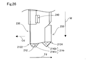
図26は、第1の他の実施形態に係る流量測定装置を側面側から見た場合の第9の模式図であり、
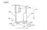
図27は、第1の他の実施形態に係る流量測定装置を側面側から見た場合の第10の模式図であり、
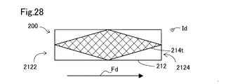
図28は、第1の他の実施形態に係る流量測定装置を先端側から見た場合の第1の模式図であり、
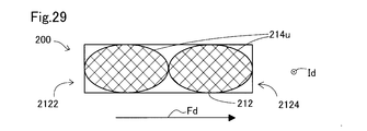
図29は、第1の他の実施形態に係る流量測定装置を先端側から見た場合の第2の模式図であり、
図30は、第1の他の実施形態に係る流量測定装置を先端側から見た場合の第3の模式図であり、
図31は、第1の他の実施形態に係る流量測定装置を入口部側から見た場合の第10の模式図であり、
図32は、第1の他の実施形態に係る流量測定装置を側面側から見た場合の第11の模式図であり、
図33は、第2の他の実施形態に係る流量測定装置を側面側から見た場合の第1の模式図であり、
図34は、第2の他の実施形態に係る流量測定装置を側面側から見た場合の第2の模式図であり、
図35は、第2の他の実施形態に係る流量測定装置を側面側から見た場合の第3の模式図である。
A.実施形態
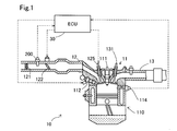
図1に示す様に、実施形態に係る流量測定装置200は、内燃機関11を備える燃焼システム10に用いられる。燃焼システム10は、内燃機関11と、配管により形成された主流路12及び排気流路13と、ECU30と、を備える。燃焼システム10は、例えば、ガソリン車に搭載され、駆動装置として用いられる。
図1に示す様に、実施形態に係る流量測定装置200は、内燃機関11を備える燃焼システム10に用いられる。燃焼システム10は、内燃機関11と、配管により形成された主流路12及び排気流路13と、ECU30と、を備える。燃焼システム10は、例えば、ガソリン車に搭載され、駆動装置として用いられる。
内燃機関11は、燃焼室110と、点火プラグ111と、燃料噴射弁112と、燃焼圧センサ114と、吸気弁125と、排気弁131と、を備える。内燃機関11は、主流路12を介して供給される空気と、燃料噴射弁112から噴射される燃料との混合ガスを燃焼させることによって動力を発生させる。点火プラグ111は、火花放電を生じさせて燃焼室110内の混合ガス(燃料と空気との混合ガス)に着火する。燃料噴射弁112は、燃焼室110内に対して燃料を噴射する。燃焼圧センサ114は、燃焼室110内の燃焼圧を検出する。
燃焼室110には、主流路12と排気流路13とが接続されている。主流路12は、空気を燃焼室110に導く流路である。排気流路13は、燃焼された後の気体である排気ガスを燃焼室110から排出する流路である。
主流路12には、上流側から順にエアクリーナ121と、流量測定装置200と、スロットルバルブ122と、が備えられている。エアクリーナ121は、主流路12を流通する空気中の塵埃を除去する。スロットルバルブ122は、開度を調整し、主流路12における流路抵抗を調整する。流量測定装置200は、主流路12内を流通する吸入空気の流量を計測する。
ECU30は、プロセッサやRAMやROMやフラッシュメモリ等の記憶媒体と、入出力部を含むマイクロコンピュータと、電源回路と、を含む演算処理回路である。ECU30は、流量測定装置200や各種センサ、例えば燃焼圧センサ114、から取得される計測結果を用いて、スロットルバルブ122の開度や燃料噴射弁112から噴射される燃料噴射量を制御する。
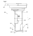
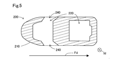
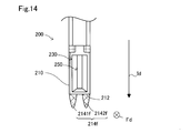
図2に示す様に、流量測定装置200は、ハウジング210と、入口部230と、出口部240と、排出口部250と、を備える。ハウジング210は、挿入方向Idに沿って延びる側面と、挿入方向Id側に位置する先端面212と、を有する。入口部230は、先端面212における入口部230の開口方向Od側の一端部2122側に設けられている。また、排出口部250は、入口部230が設けられた一端部2122側とは反対側となる他端部2124側に設けられている。本実施形態において、出口部240は2つ設けられ、図2において示された側面側に設けられた出口部240に加えて、反対側の側面にも設けられている。2つの出口部240は、それぞれハウジング210の側面のうち入口部230が設けられた面に交差する面に設けられている。
先端面212には、先端面212から挿入方向Id側に突出した突出部214が配置されている。突出部214は、一端部2122から他端部2124にわたって先端面212から挿入方向Idに突出している。本実施形態において、突出部214は、吸入空気を流通させるための内部空間を有していない。なお、突出部214の外観は、クロスハッチングによって図示されている。
本実施形態において、突出部214は、挿入方向Idにおける排出口部250の開口の下端から突出部214の先端までの第1の長さW1が排出口部250の開口幅W2の15%以上の大きさになるように先端面212から突出している。開口幅W2は、挿入方向Idにおける排出口部250の開口の幅の最大値である。また、突出部214は、挿入方向Idにおける入口部230の開口の下端から突出部214の先端までの第2の長さW3が入口部230の開口幅W4の15%以上の大きさになるように先端面212から突出している。開口幅W3は、挿入方向Idにおける入口部230の開口の幅の最大値である。
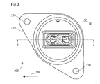
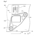
図3に示す様に、流量測定装置200を挿入方向Idの基端部側(天面側)から見た場合において、ハウジング210には、主流路12に固定するために用いられるためのボルト挿入口270が設けられている。
図4に示す様に、流量測定装置200の内部には、副流路220が形成されている。副流路220には、流量検出部260が備えられている。図4では、図3に示した4-4断面に対応した流量測定装置200の断面が示されている。ハウジング210は、合成樹脂製の筐体であり、内部に副流路220を形成する副流路形成部と、流量検出部260の保持を行う保持部と、を有する。入口部230が設けられた一端部2122は、流量測定装置200が主流路12に取り付けられた場合において主流路12の上流側に位置する。他端部2124は、流量測定装置200が主流路12に取り付けられた場合において一端部2122より下流側に位置する。
副流路220は、主流路12を流れる吸入空気の一部を流通させる流路である。本実施形態において、副流路220のうち流量検出部260の下流側では、図4における5-5断面を示す模式図である図5に示した様に、流路が2つに分岐している。分岐した副流路220は、それぞれ2つの出口部240に接続されている。
流量検出部260(図4)は、副流路220の途中に設けられ、副流路を流れる被計測流体の流量を検出する。流量検出部260は、被計測流体の流通方向が順流方向か逆流方向であるかを区別可能であることが好ましい。本実施形態において、流量検出部260には、流通方向の区別が可能な方式である温度差方式が採用されている。本実施形態において、流量検出部260は、図示しない、被計測流体を加熱する加熱ヒータと、被計測流体の流通方向に沿って配置された複数の温度センサと、を有している。本実施形態の流量検出部260は、加熱ヒータの上流側と下流側との温度差から流量を検出する。温度センサは、加熱ヒータの上流側と下流側の両方に配置されている。ここで、本実施形態において、温度センサは、感温抵抗体であり、加熱ヒータは、発熱抵抗体である。
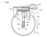
図6に示した様に、流量測定装置200の少なくとも一部は、主流路12を構成する配管の筒壁123に形成された貫通口である挿入孔124から、主流路12の内部へ挿入されている。ハウジング210は、主流路12に取り付けられた状態において、主流路12内に挿入されるハウジング本体部2100を有する。また、ハウジング200は、ハウジング本体部2100に一体的に設けられた、リング保持部2101と、フランジ部2102と、コネクタ部2103と、保護突起2104と、温度センサ2105と、を有する。フランジ部2102は、ハウジング210の基端側に備えられ、主流路12への固定部分となる。コネクタ部2103には、流量測定装置200による測定結果を外部に出力するための配線が接続される。流量測定装置200が主流路12に装着される際において、リング保持部2101は、挿入孔124にOリング126を介して取り付けられる。温度センサ2105は、吸入空気の温度を取得する。図7に示す様に、フランジ部2102には、ボルト挿入口270が形成されている。ボルト挿入口270から挿入されるボルトは、主流路12に設けられたボス125に固定される。
図6に示す様に、流量測定装置200は、入口部230側から見た場合において、主流路12の中央部を通るように取り付けられている。本実施形態において、流量測定装置200は、主流路12を流通する吸入空気を流量測定装置200の内部へ取り込むための入口部230の開口方向Odが流入空気の流通方向Fdの反対方向になるように取り付けられている。つまり、入口部230は、主流路12の上流側を向くように配置される。図6において、入口部230の奥側(+FD方向側)には排出口部250が見えている。図6に示すように、排出口部250は、開口が入口部230の開口より小さくなるように絞られている。
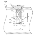
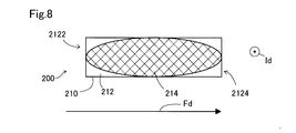
図6に示す様に、突出部214は、入口部230側から見た場合に、挿入方向の先端側に向かうにつれて細くなる先細りの形状を有する。言い換えれば、挿入方向Idと入口部230の開口方向Odとに直交する方向について、突出部214は、先端側に向かうにつれて寸法が小さくなる。先細り形状によって、突出部214は、主流路12に配置した場合に、吸入空気から受ける抵抗を低減できる。これにより、吸入空気が整流され、突出部214の周囲における吸入空気の流通が円滑になる。また、図8に示す様に、本実施形態における突出部214は、挿入方向Idの先端側から見た場合において、楕円形状である。突出部214において、一端部2122と他端部2124とが丸く、全体として細長い形をしている。このため、突出部214は、主流路12に配置した場合に、吸入空気から受ける抵抗を低減できる。これにより、吸入空気が整流され、突出部214の周囲における吸入空気の流通がさらに円滑になる。
図2に示す様に、突出部214は、入口部230の開口方向Odと挿入方向Idとに直交する方向、本実施形態において2つの出口部240の一方が設けられた側面側、から見た場合に、挿入方向Idの先端側に向かうにつれて細くなる先細りの形状を有する。この場合には、突出部214は、主流路12に配置した場合に、吸入空気から受ける抵抗を低減できる。これにより、吸入空気が整流され、突出部214の周囲における吸入空気の流通が円滑になる。なお、本実施形態において、突出部214は、側面側から見た場合に、曲面形状である。
ここで、流量測定装置200が主流路12に配置された場合には、吸入空気と流量測定装置200のハウジング210とによって摩擦が生じるため、流量測定装置200の周囲を流通する吸入空気の流速は、流れの下流に向かうに従って低下する。このため、吸入空気が流量測定装置200の形状に沿って流れることができなくなり、吸入空気の剥離が生じ得る。例えば、主流路12の上流側から下流側に向かって吸入空気が流通する順流状態では、他端部2124側において剥離が生じ得る。また例えば、主流路12の下流側から上流側に向かって吸入空気が流通する逆流状態では、一端部2122側において剥離が生じ得る。吸入空気の剥離が生じた場合には、吸入空気の横渦が生じ得る。なお、本実施形態において、横渦とは、挿入方向Idと流通方向Fdとによって規定される平面に交差する回転軸を有する渦である。
突出部214は、他端部2124において先端面212から挿入方向Idに突出し、他端部2124側における吸入空気の流れを整流する。このため、順流状態において、他端部2124において突出部214が形成されていない場合と比べて、他端部2124側における吸入空気の流量測定装置200からの剥離が低減される。これにより、他端部2124において発生する横渦を低減できる。
また例えば、主流路12の下流側から上流側に向かって吸入空気が流通する逆流状態において、吸入空気が剥離する一端部2122側の上流側圧力は他の領域における圧力より小さくなる傾向がある。この場合において、一端部2122側では、流量測定装置200の挿入方向Idに交差する方向に延びる回転軸を有する横渦が生じる。逆流状態において、一端部2122側において横渦が発生した場合には、排出口部250から流入した吸入空気の入口部230からの排出が阻害されることによって、排出口部250から流入した吸入空気が副流路220へと流れ込む場合がある。この場合には、流量測定装置200による流量の計測誤差が発生しうる。なお、逆流状態は、例えば燃焼システム10においてアイドリング運転が実行された場合に発生する。アイドリング運転が実行された場合において、燃焼システム10は、吸気弁125を閉じることによって、内燃機関11への吸入空気の流入を停止させる。この場合には、主流路12の内燃機関11側における吸入空気の圧力が上昇し、主流路12の上流側よりも下流側の圧力が高くなり、逆流が発生する。
突出部214は、一端部2122において先端面212から挿入方向Idに突出し、一端部2122側における吸入空気の流れを整流する。このため、逆流状態において、他端部2124において突出部214が形成されていない場合と比べて、一端部2122側における吸入空気の流量測定装置200からの剥離が低減される。これにより、一端部2122において発生する横渦を低減できる。
以上説明した実施形態に係る流量測定装置200によれば、突出部214は、先端面212のうち、入口部側の端部である一端部2122と、一端部2122とは反対側の端部である他端部2124と、から挿入方向Idに突出している。このため、入口部230が主流路12の流通方向Fdに対向する様に主流路12に取り付けられた場合において、流量測定装置200は、吸入空気の剥離が先端面212よりさらに先端側に位置する突出部214で生じる。これにより、突出部214が設けられていない場合より、横渦の発生位置と入口部230や排出口部250との距離を大きくすることができる。したがって、順流状態と逆流状態の両方の状態において、横渦による影響、例えば横渦による入口部230や排出口部250への吸入空気の流入や吸入空気の排出の阻害、が抑制される。これにより、横渦の発生に起因する流量測定装置200の流量の計測誤差が低減される。また突出部214は、横渦の発生を抑制する機能である整流機能を有する。これにより、流量測定装置200の流量の計測誤差がさらに低減される。
また以上説明した実施形態に係る流量測定装置200によれば、突出部214は、一端部2122から他端部2124にわたって設けられている。この場合には、例えば、不連続な構造である場合において発生しうる一端部2122側の突出部と他端部2124側の突出部との間における横渦が生じない。したがって、一端部2122側と他端部2124側とで突出部214が不連続な構造を有している場合と比べて、整流機能が向上する。
また以上説明した実施形態に係る流量測定装置200によれば、突出部214は、第1の長さW1が排出口部250における開口幅W2の15%以上の大きさになるように先端面212から突出している。このため、順流状態において、排出口部250と横渦の発生位置との距離を大きくすることが容易である。また、突出部214は、第2の長さW3が入口部230における開口幅W4の15%以上の大きさになるように先端面212から突出している。したがって、順流状態と逆流状態の両方の状態において、横渦による影響を抑制する効果の向上が容易になる。このため、逆流状態において、入口部230と横渦の発生位置との距離を大きくすることが容易である。また、第1の長さW1及び第2の長さW3が大きい場合には、突出部214を先細り形状にするのが容易になる。
B.他の実施形態
B1.第1の他の実施形態
実施形態に係る流量測定装置200における突出部214の形状は、少なくとも一端部2122と他端部2124とにおいて、挿入方向Idに突出している限りにおいて、適宜変更可能である。以下では、図9から図32を用いて、採用可能な突出部214の形状の一例を説明する。
B1.第1の他の実施形態
実施形態に係る流量測定装置200における突出部214の形状は、少なくとも一端部2122と他端部2124とにおいて、挿入方向Idに突出している限りにおいて、適宜変更可能である。以下では、図9から図32を用いて、採用可能な突出部214の形状の一例を説明する。
図9から図12に示す様に、突出部214a~214dは、入口部230側から見た場合の形状が、先細り形状であれば上記実施形態と異なっていてもよい。例えば、図9に示した突出部214aにおいて、挿入方向Id側の端部は平面形状である。また例えば図10に示した突出部214bは、挿入方向Id側の端面は上記例と同様に平面形状であるとともに、側面が平面であって傾斜している。また例えば図11に示した突出部214cは、図10に示した突出部214bと同様に側面が平面であって傾斜するとともに、挿入方向Id側の端部は曲面形状である。また例えば図12に示した突出部214dは、図10及び図11に示した突出部214b、214cと同様に側面が傾斜しているが、挿入方向Id側の端部が尖った形状である。また、図13と図14に示す様に、流量測定装置200は、複数の突出部214e、214fを有していてもよい。この場合において、図13に示した様に、複数の突出部214は、挿入方向Idと開口方向Odとに直交する方向において、互いに隣接して設けられていてもよい。また図14に示した様に、複数の突出部214は、挿入方向Idと開口方向Odとに直交する方向において、互いに距離を置いて設けられていてもよい。また、図15から図17に示す様に、流量測定装置200が複数の突出部214g~214iを有している場合において、複数の突出部214g~214iはそれぞれ異なる形状を有していても良い。例えば図15に示した突出部214gにおいて、一方の突出部2141gは、曲面によって形成されている。他方の突出部2142gは、側面が傾斜し、挿入方向Id側の端部が尖った形状である。また、例えば図16に示した突出部214hにおいて、一方の突出部2141hは、側面が平面であって傾斜するとともに、挿入方向Id側の端部は平面形状である。他方の突出部2142hは、側面が傾斜し、挿入方向Id側の端部が尖った形状である。また、例えば図17に示した突出部214iにおいて、一方の突出部2141iは、曲面によって形成されている。他方の突出部2142iは、側面が傾斜し、挿入方向Id側の端部が尖った形状である。
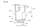
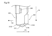
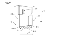
図18から図24に示す様に、突出部214j~214pは、入口部230の開口方向Odと挿入方向Idとの両方とに直交する方向から見た場合、つまり側面側から見た場合の形状が、実施形態と異なっていてもよい。例えば図18に示した突出部214jでは、側面側から見た場合に、一端部2122側と他端部2124側とが挿入方向Idの先端側に向かって傾斜し、挿入方向Id側の端部は平面形状である。また例えば図19に示した突出部214kでは、側面側から見た場合に、一端部2122側と他端部2124側とが挿入方向Idの先端側に向かって傾斜し、挿入方向Id側の端部は尖った形状である。例えば図20に示した突出部214lでは、側面側から見た場合に、一端部2122側と他端部2124側とが曲面形状であり、挿入方向Id側の端部は平面形状である。また例えば図21に示した突出部214mでは、側面側から見た場合に、一端部2122は挿入方向Idに沿って延び、他端部2124側は挿入方向Idの先端側に向かって傾斜している。突出部214mにおいて、挿入方向Id側の端部は平面形状である。また、例えば図22に示した突出部214nでは、側面側から見た場合に、一端部2122側は挿入方向Idの先端側に向かって傾斜し、他端部2124は挿入方向Idに沿って延びている。突出部214nにおいて、挿入方向Id側の端部は平面形状である。また、例えば図23に示した突出部214oでは、側面側から見た場合に、一端部2122側は曲面形状であり、他端部2124は挿入方向Idに沿って延びている。突出部214oにおいて、挿入方向Id側の端部は平面形状である。また、例えば図24に示した突出部214pでは、側面側から見た場合に、一端部2122側と他端部2124側とが挿入方向Idの先端側に向かって傾斜し、挿入方向Id側の端部は曲面形状である。
また図25から図27に示す様に、流量測定装置200は、一端部2122から他端部2124までの間の一部において突出部214q~214sが設けられていない領域を有していても良い。例えば図25に示した突出部214qでは、一端部2122側と他端部2124側とにそれぞれ曲面形状の突出部2141q、2142qを有する。また、一端部2122から他端部2124までの間の一部において突出部214r、214sが設けられていない領域を有していない場合において、一端部2122側と他端部2124側とで、それぞれ異なる形状の突出部214r、214sを有していても良い。例えば、図26に示した突出部214rでは、一端部2122側の突出部2141rは、一端部2122側と他端部2124側とが傾斜し、挿入方向Id側の端部が平面形状である。また他端部2124側の突出部2142rは、一端部2122側と他端部2124側とが傾斜し、挿入方向Id側の端部が尖った形状である。例えば、図27に示した突出部214sでは、一端部2122側の突出部2141sは、一端部2122側と他端部2124側とが傾斜し、挿入方向Id側の端部が平面形状である。また他端部2124側の突出部2142sは、曲線形状である。
また、図28から図30に示す様に、突出部214t~214vは、挿入方向Idと逆の方向から見た場合、つまり先端側から見た場合の形状が、実施形態と異なっていても良い。例えば図28に示す突出部214tは、先端側から見た場合に、菱形状である。また、流量測定装置200は、複数の突出部214u、214vを備えていてもよい。この場合において、例えば図29および図30に示す様に、流量測定装置200は、流通方向Fdに沿って配置された2つの突出部214u、214vを備えていても良い。具体的には、例えば、図29に示した突出部214uは、先端側から見た場合に、楕円形状である2つの突出部2141u、2142uを有する。また例えば、図30に示した突出部214vは、先端側から見た場合に、菱形状である2つの突出部2141v、2142vを有する。
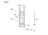
また上記実施形態において、突出部214は、入口部230に対向した方向から見た場合に、挿入方向の先端側に向かうにつれて細くなる先細りの形状を有しているが、突出部214の形状はこれに限定されない。例えば、図31に示す様に、突出部214wの形状は、入口部230側から見た場合に、挿入方向Idにおいて一定の幅を有する形状であってもよい。
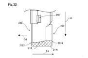
また上記実施形態において、突出部214は、側面側から見た場合に、挿入方向Idの先端側に向かうにつれて細くなる先細りの形状を有する。しかし、突出部214の形状はこれに限定されない。例えば、図32に示す様に、突出部214xの形状は、側面側から見た場合に、挿入方向において一定の幅を有する形状であってもよい。
B2.第2の他の実施形態
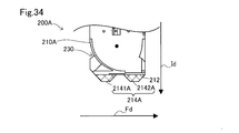
例えば、図33に示す様に、流量測定装置200Aは、実施形態とは異なる構造のハウジング210Aを有していても良い。例えば、流量測定装置200Aは、副流路220の下流側に分岐流路を有していなくてもよい。また、出口部240は、1つであってもよい。また、出口部240は、他端部2124側の壁面に設けられていてもよい。また、例えば、図34と図35に示す様に、流量測定装置200Aは、種々の形状の突出部214A、214Bを有していても良い。図34及び図35に示す様に、流量測定装置200Aは、複数の突出部214A、214Bを備えていてもよい。例えば、図34に示す様に、2つの突出部2141A、2142Aは、側面が平面であって傾斜するとともに、挿入方向Id側の端部は平面形状である。また例えば、図35に示す様に、2つの突出部214Bのうち一方の突出部2141Bは、側面が平面であって傾斜するとともに、挿入方向Id側の端部は尖った形状である。また他方の突出部2142Bは、側面が平面であって傾斜するとともに、挿入方向Id側の端部は平面形状である。
例えば、図33に示す様に、流量測定装置200Aは、実施形態とは異なる構造のハウジング210Aを有していても良い。例えば、流量測定装置200Aは、副流路220の下流側に分岐流路を有していなくてもよい。また、出口部240は、1つであってもよい。また、出口部240は、他端部2124側の壁面に設けられていてもよい。また、例えば、図34と図35に示す様に、流量測定装置200Aは、種々の形状の突出部214A、214Bを有していても良い。図34及び図35に示す様に、流量測定装置200Aは、複数の突出部214A、214Bを備えていてもよい。例えば、図34に示す様に、2つの突出部2141A、2142Aは、側面が平面であって傾斜するとともに、挿入方向Id側の端部は平面形状である。また例えば、図35に示す様に、2つの突出部214Bのうち一方の突出部2141Bは、側面が平面であって傾斜するとともに、挿入方向Id側の端部は尖った形状である。また他方の突出部2142Bは、側面が平面であって傾斜するとともに、挿入方向Id側の端部は平面形状である。
B3.第3の他の実施形態
上記実施形態において、流量測定装置200は、一部が主流路12の内部に挿入されているが、全体が主流路12に挿入された状態で取り付けられていても良い。
上記実施形態において、流量測定装置200は、一部が主流路12の内部に挿入されているが、全体が主流路12に挿入された状態で取り付けられていても良い。
B4.第4の他の実施形態
上記実施形態において、流量測定装置200は、異なる流路構造を有していても良い。例えば、出口部240は、3以上であってもよい。また例えば、入口部230は、2以上であってもよい。また例えば、流量測定装置200は、排出口部250を備えていなくても良い。
上記実施形態において、流量測定装置200は、異なる流路構造を有していても良い。例えば、出口部240は、3以上であってもよい。また例えば、入口部230は、2以上であってもよい。また例えば、流量測定装置200は、排出口部250を備えていなくても良い。
B5.第5の他の実施形態
上記実施形態において、流量測定装置200は、燃焼システム10において用いられているが、燃焼システム10以外に用いられても良い。例えば、流量測定装置200は、酸化剤ガスとして空気を用いる燃料電池システムにおける空気供給系の空気供給用配管に取り付けられてもよい。
上記実施形態において、流量測定装置200は、燃焼システム10において用いられているが、燃焼システム10以外に用いられても良い。例えば、流量測定装置200は、酸化剤ガスとして空気を用いる燃料電池システムにおける空気供給系の空気供給用配管に取り付けられてもよい。
B6.第6の他の実施形態
上記実施形態において、突出部214は、第1の長さW1が排出口部250の開口幅W2の15%以上になるように先端面212から突出している。また突出部214は、第2の長さW3が入口部230の開口幅W4の15%以上の大きさになるように先端面212から突出している。しかし、突出部214の大きさは、これに限定されない。例えば、突出部214は、順流状態と逆流状態の両方の状態において、横渦による影響を抑制可能な程度に先端面212から突出していればよい。具体的には、突出部214は、例えば、長さW1が排出口部250の開口幅W2の10%以上の大きさになるように突出していればよい。この場合であっても、突出部214は、第1の長さW1が開口幅W2の10%未満である場合と比べて、順流状態における横渦の影響の低減が可能である。また、例えば、突出部214は、第2の長さW3が入口部230の開口幅W4の10%以上の大きさになるように突出していればよい。この場合であっても、突出部214は、第2の長さW3が開口幅W4の10%未満である場合と比べて、逆流状態における横渦の影響の低減が可能である。なお、突出部214は、第1の長さW2が排出口部250の開口幅W3の15%以上の大きさになるように先端面212から突出していることが好ましい。また、突出部214は、第2の長さW3が開口幅W4の15%以上の大きさになるように先端面212から突出していることが好ましい。
上記実施形態において、突出部214は、第1の長さW1が排出口部250の開口幅W2の15%以上になるように先端面212から突出している。また突出部214は、第2の長さW3が入口部230の開口幅W4の15%以上の大きさになるように先端面212から突出している。しかし、突出部214の大きさは、これに限定されない。例えば、突出部214は、順流状態と逆流状態の両方の状態において、横渦による影響を抑制可能な程度に先端面212から突出していればよい。具体的には、突出部214は、例えば、長さW1が排出口部250の開口幅W2の10%以上の大きさになるように突出していればよい。この場合であっても、突出部214は、第1の長さW1が開口幅W2の10%未満である場合と比べて、順流状態における横渦の影響の低減が可能である。また、例えば、突出部214は、第2の長さW3が入口部230の開口幅W4の10%以上の大きさになるように突出していればよい。この場合であっても、突出部214は、第2の長さW3が開口幅W4の10%未満である場合と比べて、逆流状態における横渦の影響の低減が可能である。なお、突出部214は、第1の長さW2が排出口部250の開口幅W3の15%以上の大きさになるように先端面212から突出していることが好ましい。また、突出部214は、第2の長さW3が開口幅W4の15%以上の大きさになるように先端面212から突出していることが好ましい。
以上説明した第1から第6の他の実施形態によれば、上記実施形態と同様の構成を有する点において、同様の効果を奏する。
本開示は、上述の実施形態に限られるものではなく、その趣旨を逸脱しない範囲において種々の構成で実現することができる。例えば、発明の概要の欄に記載した各形態中の技術的特徴に対応する本実施形態中の技術的特徴は、上述の課題の一部又は全部を解決するために、あるいは、上述の効果の一部又は全部を達成するために、適宜、差し替えや、組み合わせを行うことが可能である。また、その技術的特徴が本明細書中に必須なものとして説明されていなければ、適宜、削除することが可能である。
Claims (4)
- 被計測流体が流れる主流路(12)に挿入された状態で前記主流路に取り付けられ、前記主流路における前記被計測流体の流量を測定する流量測定装置(200)であって、
前記流量測定装置の前記主流路への挿入方向に沿って延びる側面と前記挿入方向側に位置する先端面とを有するハウジングと、
前記ハウジングの内部に形成され、前記主流路を流れる前記被検出流体の一部を流通させる副流路(220)と、
前記側面に設けられ、前記主流路を流れる前記被計測流体を前記副流路内へと流入させる入口部(230)と、
前記副流路内を流れる前記被計測流体を前記主流路へと流出させる出口部(240)と、
前記副流路を流れる前記被計測流体の流量を検出する流量検出部(260)と、
前記先端面から前記挿入方向に突出した突出部(214)と、を備え、
前記突出部は、前記先端面のうち少なくとも、前記入口部側の端部である一端部(2122)と、前記一端部とは反対側の端部である他端部(2124)と、に配置されている、流量測定装置。 - 請求項1に記載の流量測定装置であって、
前記突出部は、前記一端部から前記他端部にわたって設けられている、流量測定装置。 - 請求項1または請求項2に記載の流量測定装置であって、
前記突出部は、前記入口部側から見た場合に、前記挿入方向側に向かうにつれて細くなる形状を有する、流量測定装置。 - 請求項1から請求項3までのいずれか一項に記載の流量測定装置であって、
前記突出部は、前記入口部の開口方向と前記挿入方向とに直交する方向から見た場合に、前記挿入方向側に向かうにつれて細くなる形状を有する、流量測定装置。
Priority Applications (2)
| Application Number | Priority Date | Filing Date | Title |
|---|---|---|---|
| DE112019003970.9T DE112019003970T5 (de) | 2018-08-08 | 2019-06-20 | Strömungsmesser |
| US17/168,908 US11262223B2 (en) | 2018-08-08 | 2021-02-05 | Flowmeter |
Applications Claiming Priority (2)
| Application Number | Priority Date | Filing Date | Title |
|---|---|---|---|
| JP2018-149045 | 2018-08-08 | ||
| JP2018149045A JP7204370B2 (ja) | 2018-08-08 | 2018-08-08 | 流量計測装置 |
Related Child Applications (1)
| Application Number | Title | Priority Date | Filing Date |
|---|---|---|---|
| US17/168,908 Continuation US11262223B2 (en) | 2018-08-08 | 2021-02-05 | Flowmeter |
Publications (1)
| Publication Number | Publication Date |
|---|---|
| WO2020031518A1 true WO2020031518A1 (ja) | 2020-02-13 |
Family
ID=69415554
Family Applications (1)
| Application Number | Title | Priority Date | Filing Date |
|---|---|---|---|
| PCT/JP2019/024444 WO2020031518A1 (ja) | 2018-08-08 | 2019-06-20 | 流量計測装置 |
Country Status (4)
| Country | Link |
|---|---|
| US (1) | US11262223B2 (ja) |
| JP (1) | JP7204370B2 (ja) |
| DE (1) | DE112019003970T5 (ja) |
| WO (1) | WO2020031518A1 (ja) |
Citations (5)
| Publication number | Priority date | Publication date | Assignee | Title |
|---|---|---|---|---|
| JPH10332453A (ja) * | 1997-05-28 | 1998-12-18 | Mitsubishi Electric Corp | 感熱式流量センサおよび内燃機関の吸気装置 |
| JP2000346688A (ja) * | 1999-06-08 | 2000-12-15 | Mitsubishi Electric Corp | 流量センサ |
| JP2010014489A (ja) * | 2008-07-02 | 2010-01-21 | Mitsubishi Electric Corp | 流量測定装置 |
| JP2011112569A (ja) * | 2009-11-27 | 2011-06-09 | Denso Corp | 空気流量測定装置 |
| WO2017073276A1 (ja) * | 2015-10-28 | 2017-05-04 | 日立オートモティブシステムズ株式会社 | 熱式流量計 |
Family Cites Families (4)
| Publication number | Priority date | Publication date | Assignee | Title |
|---|---|---|---|---|
| JP2003329495A (ja) * | 2002-05-13 | 2003-11-19 | Mitsubishi Electric Corp | 空気流量測定装置およびその取り付け構造 |
| JP4488031B2 (ja) * | 2007-06-14 | 2010-06-23 | 株式会社デンソー | 空気流量測定装置 |
| JP6690899B2 (ja) * | 2015-06-29 | 2020-04-28 | 株式会社デンソー | 空気流量測定装置 |
| US20200200613A1 (en) * | 2017-09-29 | 2020-06-25 | Hitachi Automotive Systems, Ltd. | Physical quantity detection device |
-
2018
- 2018-08-08 JP JP2018149045A patent/JP7204370B2/ja active Active
-
2019
- 2019-06-20 DE DE112019003970.9T patent/DE112019003970T5/de active Pending
- 2019-06-20 WO PCT/JP2019/024444 patent/WO2020031518A1/ja active Application Filing
-
2021
- 2021-02-05 US US17/168,908 patent/US11262223B2/en active Active
Patent Citations (5)
| Publication number | Priority date | Publication date | Assignee | Title |
|---|---|---|---|---|
| JPH10332453A (ja) * | 1997-05-28 | 1998-12-18 | Mitsubishi Electric Corp | 感熱式流量センサおよび内燃機関の吸気装置 |
| JP2000346688A (ja) * | 1999-06-08 | 2000-12-15 | Mitsubishi Electric Corp | 流量センサ |
| JP2010014489A (ja) * | 2008-07-02 | 2010-01-21 | Mitsubishi Electric Corp | 流量測定装置 |
| JP2011112569A (ja) * | 2009-11-27 | 2011-06-09 | Denso Corp | 空気流量測定装置 |
| WO2017073276A1 (ja) * | 2015-10-28 | 2017-05-04 | 日立オートモティブシステムズ株式会社 | 熱式流量計 |
Also Published As
| Publication number | Publication date |
|---|---|
| US20210156721A1 (en) | 2021-05-27 |
| DE112019003970T5 (de) | 2021-04-15 |
| JP2020024151A (ja) | 2020-02-13 |
| US11262223B2 (en) | 2022-03-01 |
| JP7204370B2 (ja) | 2023-01-16 |
Similar Documents
| Publication | Publication Date | Title |
|---|---|---|
| US7043978B2 (en) | Airflow meter | |
| US8701474B2 (en) | Air flow measuring device | |
| JP6502573B2 (ja) | 熱式流量計 | |
| JP2022084957A (ja) | 物理量計測装置 | |
| JP6114673B2 (ja) | 熱式流量計 | |
| JP6838249B2 (ja) | 熱式流量計 | |
| CN108139248B (zh) | 热式流量计 | |
| WO2020031518A1 (ja) | 流量計測装置 | |
| WO2020202722A1 (ja) | 物理量検出装置 | |
| JP2015068793A (ja) | 熱式流量計 | |
| JP6438707B2 (ja) | 熱式流量計 | |
| WO2017208640A1 (ja) | 熱式流量計 | |
| JP7168390B2 (ja) | 流量測定装置 | |
| US11391610B2 (en) | Flow rate measurement device | |
| JP6995020B2 (ja) | 物理量検出装置 | |
| JPS5861411A (ja) | 気体流量測定装置 | |
| WO2020059540A1 (ja) | 流量測定装置 | |
| US10718647B2 (en) | Thermal flowmeter including an inclined passage | |
| JP7097333B2 (ja) | 物理量検出装置 | |
| WO2019142565A1 (ja) | 熱式流量計 | |
| JP2020098179A (ja) | 物理量測定装置 |
Legal Events
| Date | Code | Title | Description |
|---|---|---|---|
| 121 | Ep: the epo has been informed by wipo that ep was designated in this application |
Ref document number: 19847904 Country of ref document: EP Kind code of ref document: A1 |
|
| 122 | Ep: pct application non-entry in european phase |
Ref document number: 19847904 Country of ref document: EP Kind code of ref document: A1 |