WO2020031454A1 - 自動車用排熱回収装置 - Google Patents
自動車用排熱回収装置 Download PDFInfo
- Publication number
- WO2020031454A1 WO2020031454A1 PCT/JP2019/019743 JP2019019743W WO2020031454A1 WO 2020031454 A1 WO2020031454 A1 WO 2020031454A1 JP 2019019743 W JP2019019743 W JP 2019019743W WO 2020031454 A1 WO2020031454 A1 WO 2020031454A1
- Authority
- WO
- WIPO (PCT)
- Prior art keywords
- flat flow
- fluid
- flow pipe
- flat
- pipe group
- Prior art date
- Legal status (The legal status is an assumption and is not a legal conclusion. Google has not performed a legal analysis and makes no representation as to the accuracy of the status listed.)
- Ceased
Links
Images


Classifications
-
- F—MECHANICAL ENGINEERING; LIGHTING; HEATING; WEAPONS; BLASTING
- F01—MACHINES OR ENGINES IN GENERAL; ENGINE PLANTS IN GENERAL; STEAM ENGINES
- F01N—GAS-FLOW SILENCERS OR EXHAUST APPARATUS FOR MACHINES OR ENGINES IN GENERAL; GAS-FLOW SILENCERS OR EXHAUST APPARATUS FOR INTERNAL-COMBUSTION ENGINES
- F01N5/00—Exhaust or silencing apparatus combined or associated with devices profiting by exhaust energy
- F01N5/02—Exhaust or silencing apparatus combined or associated with devices profiting by exhaust energy the devices using heat
-
- F—MECHANICAL ENGINEERING; LIGHTING; HEATING; WEAPONS; BLASTING
- F01—MACHINES OR ENGINES IN GENERAL; ENGINE PLANTS IN GENERAL; STEAM ENGINES
- F01N—GAS-FLOW SILENCERS OR EXHAUST APPARATUS FOR MACHINES OR ENGINES IN GENERAL; GAS-FLOW SILENCERS OR EXHAUST APPARATUS FOR INTERNAL-COMBUSTION ENGINES
- F01N13/00—Exhaust or silencing apparatus characterised by constructional features
- F01N13/08—Other arrangements or adaptations of exhaust conduits
-
- F—MECHANICAL ENGINEERING; LIGHTING; HEATING; WEAPONS; BLASTING
- F01—MACHINES OR ENGINES IN GENERAL; ENGINE PLANTS IN GENERAL; STEAM ENGINES
- F01N—GAS-FLOW SILENCERS OR EXHAUST APPARATUS FOR MACHINES OR ENGINES IN GENERAL; GAS-FLOW SILENCERS OR EXHAUST APPARATUS FOR INTERNAL-COMBUSTION ENGINES
- F01N2240/00—Combination or association of two or more different exhaust treating devices, or of at least one such device with an auxiliary device, not covered by indexing codes F01N2230/00 or F01N2250/00, one of the devices being
- F01N2240/02—Combination or association of two or more different exhaust treating devices, or of at least one such device with an auxiliary device, not covered by indexing codes F01N2230/00 or F01N2250/00, one of the devices being a heat exchanger
-
- F—MECHANICAL ENGINEERING; LIGHTING; HEATING; WEAPONS; BLASTING
- F01—MACHINES OR ENGINES IN GENERAL; ENGINE PLANTS IN GENERAL; STEAM ENGINES
- F01N—GAS-FLOW SILENCERS OR EXHAUST APPARATUS FOR MACHINES OR ENGINES IN GENERAL; GAS-FLOW SILENCERS OR EXHAUST APPARATUS FOR INTERNAL-COMBUSTION ENGINES
- F01N2240/00—Combination or association of two or more different exhaust treating devices, or of at least one such device with an auxiliary device, not covered by indexing codes F01N2230/00 or F01N2250/00, one of the devices being
- F01N2240/36—Combination or association of two or more different exhaust treating devices, or of at least one such device with an auxiliary device, not covered by indexing codes F01N2230/00 or F01N2250/00, one of the devices being an exhaust flap
-
- Y—GENERAL TAGGING OF NEW TECHNOLOGICAL DEVELOPMENTS; GENERAL TAGGING OF CROSS-SECTIONAL TECHNOLOGIES SPANNING OVER SEVERAL SECTIONS OF THE IPC; TECHNICAL SUBJECTS COVERED BY FORMER USPC CROSS-REFERENCE ART COLLECTIONS [XRACs] AND DIGESTS
- Y02—TECHNOLOGIES OR APPLICATIONS FOR MITIGATION OR ADAPTATION AGAINST CLIMATE CHANGE
- Y02T—CLIMATE CHANGE MITIGATION TECHNOLOGIES RELATED TO TRANSPORTATION
- Y02T10/00—Road transport of goods or passengers
- Y02T10/10—Internal combustion engine [ICE] based vehicles
- Y02T10/12—Improving ICE efficiencies
Definitions
- the present invention relates to an exhaust heat recovery apparatus that recovers and uses exhaust heat such as exhaust gas from an internal combustion engine of an automobile.
- Patent Literature 1 discloses an exhaust gas introduction section into which exhaust gas generated by an internal combustion engine is introduced, a heat recovery path connected to an upper portion on the downstream side of the exhaust gas introduction section, and an exhaust gas introduction section provided below the heat recovery path.
- a detour connected to the lower part on the downstream side, a heat recovery unit mounted on the upper surface of the detour and heating the cooling water with exhaust air sent from the heat recovery path, and rotatable upstream or downstream of the detour and the heat recovery path
- An exhaust heat recovery apparatus for a vehicle which is provided with a valve that is provided in the vehicle and closes either the detour or the heat recovery path and regulates the flow of exhaust gas is disclosed.
- the heat recovery unit of the exhaust heat recovery device is provided with a plurality of flat tubular heat plates through which the exhaust gas passes in the core case, and heats the cooling water flowing in the core case by the heat of the exhaust gas flowing through the heat plate. It has become.
- the fluid for performing heat exchange such as cooling water is the same as that on the introduction side according to the state of the installation place in the vehicle. There is also a need for a structure that can be led to the side.
- the present invention has been proposed in view of the above problems, and can significantly improve the heat exchange efficiency, and can lead a fluid for heat exchange such as cooling water to the same side as the introduction side, so that the It is an object of the present invention to provide an exhaust heat recovery device for a vehicle, which can increase the degree of freedom of an installation place in a vehicle.
- the exhaust heat recovery device for a vehicle is provided with a base through which the first fluid flows, and extends at an angle to the flow direction of the first fluid, and has a flat surface along the flow direction of the first fluid.
- a flat flow pipe through which a second fluid that exchanges heat with the first fluid flows, and a flat flow pipe group on the upstream side and a flat flow pipe group on the downstream side in the flow direction of the first fluid,
- a plurality of the flat flow pipes are arranged side by side at intervals in a direction substantially perpendicular to the flow direction of the first fluid, and the first flow of the first fluid in the flat flow pipes of the downstream flat flow pipe group is configured.
- An upstream end in the flow direction is provided so as not to overlap with the flat flow tube of the upstream flat flow tube group in the flow direction of the first fluid, and the upstream flat flow tube group is provided. And make a U-turn between the downstream flat flow pipe group and Wherein the flow path where the second fluid flows is formed.
- the heat exchange area can be increased by arranging the flat flow pipes along the flow direction of the first fluid and juxtaposing the flat flow pipes at intervals.
- the downstream flat flow pipe has a temperature difference between the second fluid and the second fluid.
- the heat exchange performance can be enhanced by applying a large first fluid. Therefore, the heat exchange efficiency can be significantly improved.
- the structure in which the second fluid flows in a U-turn between the upstream flat flow pipe group and the downstream flat flow pipe group to flow the fluid performing heat exchange such as cooling water to the same side as the introduction side can be increased.
- the degree of freedom of an installation location of the exhaust heat recovery device for a vehicle in the vehicle can be increased.
- the flat shape and arrangement of the flat flow pipe the pressure loss of the first fluid flowing through the base can be reduced, and a smooth flow of the first fluid can be ensured.
- the back pressure of the internal combustion engine can be reduced by reducing the pressure loss, and the exhaust efficiency, intake efficiency, and combustion efficiency of the internal combustion engine can be increased.
- the exhaust heat recovery apparatus for an automobile is characterized in that the upstream flat flow pipe group and the downstream flat flow pipe group are inserted all at once into the same heat transfer fin, and the upstream flat flow pipe is A plurality of heat transfer fins are provided at intervals in a pipe direction in which the group and the downstream flat flow pipe group extend. According to this, the heat exchange efficiency can be further improved by providing a plurality of heat transfer fins at intervals in a pipe direction in which the upstream flat flow pipe group and the downstream flat flow pipe group extend. . In addition, by inserting the upstream flat flow pipe group and the downstream flat flow pipe group into the same heat transfer fin, the heat transfer fin is attached, so that the upstream flat flow pipe group and the downstream flat flow pipe are attached. Groups can be easily integrated and assembled.
- the exhaust heat recovery device for a vehicle includes a first partition portion in which one end opening of each of the flat flow pipe groups of the upstream flat flow pipe group is opened, and each of the downstream flat flow pipe groups.
- One end opening of the flat flow pipe is opened, and a second partition section partitioned from the first partition section is provided, and the second fluid is externally supplied to one of the first partition section and the second partition section.
- the second fluid is introduced to the outside from the other, and the other end opening of each of the flat flow pipes in the upstream flat flow pipe group and the flat in each of the downstream flat flow pipe groups are set.
- a U-turn partition is provided in which the other end opening of the flow pipe is opened.
- the introduction and the derivation of the second fluid into the upstream flat flow pipe group and the downstream flat flow pipe group can be easily performed.
- the U-turn section eliminates the need for a complicated structure such as connecting the individual flat flow pipes on the upstream side to the flat flow pipes on the downstream side by shifting the positions of the flat flow pipes in the stacking direction, and eliminating the second fluid. Can be simplified and the cost can be reduced.
- the second fluids derived from the individual flat flow pipes of the upstream or downstream flat flow pipe group are mixed inside the U-turn section, turbulence and agitation are promoted to reduce temperature unevenness. The heat exchange efficiency can be further improved.
- the base is formed by joining a pair of halves so as to be aligned in a pipe direction of the flat flow pipe, and a through hole of one half and the other half are formed. Both ends of each of the flat flow pipes are fitted and welded to the through holes of the body. According to this, the pair of halves joined so as to be aligned in the pipe direction of the flat flow pipe, the flat flow pipe is easily and reliably positioned with respect to the base, and the flat flow pipe is fixed in a bridged state. can do.
- the base is formed by joining a pair of halves so as to be joined in a pipe direction of the flat flow pipe, and is provided at a joining portion of one of the halves.
- the fitting portion is fitted to a fitted portion provided at a mating portion of the other half.
- the exhaust heat recovery device for a vehicle has a fluid introduction part, a fluid lead-out part, a swelling part between the fluid introduction part and the fluid lead-out part, and a pair of halves is formed of the flat flow pipe.
- the base formed by being joined so as to be joined in the road direction, and extending in the flow direction of the first fluid flowing through the base, and generally dividing the inside of the bulging portion into a heat exchange path and a detour.
- a tilt valve that can be switched to restrict the flow of the first fluid flowing through the base to any one of the heat exchange path and the detour, and the upstream flat flow pipe group and the The flat flow pipe group on the downstream side is provided so that the first fluid flowing through the heat exchange path flows around the first fluid.
- the heat exchange path and the detour can be formed by the base formed by joining the pair of halves and the separator that substantially divides the inside of the bulge of the base, so that the switchable heat
- An automobile exhaust heat recovery device having an exchange path and a detour can be formed with a small number of parts. Therefore, the number of parts to be joined is reduced, so that the manufacturing efficiency can be improved. In addition, the cost of parts and the cost of the joining operation can be reduced, and the manufacturing cost can be reduced. In addition, since the number of parts is small, the weight of the exhaust heat recovery device for an automobile can be reduced, and the fuel efficiency of the automobile can be improved by reducing the weight.
- the exhaust heat recovery device for a vehicle according to the present invention is characterized in that the separator, the tilt valve, and the flat flow pipe are bridged between the halves. According to this, the separator, the tilt valve, and the flat flow pipe can be easily installed on the base body in cooperation with the operation of aligning the pair of halves with each other in the pipe direction of the flat flow pipe.
- the heat exchange efficiency can be significantly improved, and the fluid for performing heat exchange such as cooling water can be led out to the same side as the introduction side, so that the The degree of freedom of the installation location can be increased.
- FIG. 1 is a perspective view of an exhaust heat recovery device for a vehicle according to an embodiment of the present invention.
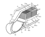
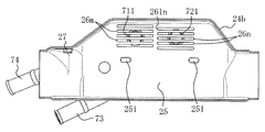
- FIG. 1 is an exploded perspective view of an exhaust heat recovery device for a vehicle according to an embodiment. The perspective view in the state where the flat distribution pipe, the separator, and the tilt valve were arranged in one half in the exhaust heat recovery device for vehicles of the embodiment. The front view which looked at the other half and the division unit in the exhaust heat recovery device for vehicles of an embodiment from the inside.
- FIG. 5 is a front view of a state where the other half is removed from the state of FIG. 4.
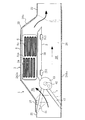
- FIG. 4 is a partial vertical explanatory view illustrating a heat exchange operation of the exhaust heat recovery device for a vehicle according to the embodiment.
- the exhaust heat recovery apparatus 1 for an automobile includes a substantially cylindrical fluid introduction unit 21, a substantially cylindrical fluid lead-out unit 22, and a fluid introduction unit 21. It has a bulging portion 23 provided between the fluid guiding portion 22 and the base 2 through which the first fluid flows.
- the bulging portion 23 bulges outward so as to form a wide space inside, and the base 2 is formed in a substantially tubular shape having a bulge at an intermediate portion as a whole.
- the base 2 is formed such that the axis of the substantially cylindrical fluid introduction part 21 and the axis of the substantially cylindrical fluid lead-out part 22 substantially coincide with each other.
- the protruding portion 22 is formed so as to protrude laterally in one direction.
- the base 2 is formed by joining the pair of halves 24a and 24b.
- the halves 24a and 24b have a shape in which the base 2 is divided into two in the axial direction of the fluid introduction part 21 and the fluid outlet part 22 and in the direction in which the bulging part 23 projects, and the halves 24a and 24b are substantially the same. It is almost the same size in shape.
- the pair of halves 24a, 24b of the present embodiment are joined together so as to fit in the direction of the flat flow pipes 5m, 5n described later.
- the joining portions of the half body 24a and the half body 24b have their end faces abutting on the upstream end of the fluid introduction part 21 and the downstream end of the fluid outlet part 22, and are fitted in the middle part thereof.
- the mating portion 241a and the fitted portion 241b are formed so as to bulge outward at different heights, and the fitting portion 241a is fitted inside the fitted portion 241b. Then, the contacted end surface and the overlapping surface of the fitting portion 241a and the fitted portion 241b or the end of the fitted portion 241b are welded by laser welding or the like, and the half body 24a and the half body 24b are joined. , As a base 2.
- a mounting portion 251 is formed at a predetermined position on the wall portion 25 corresponding to the bulging portion 23 of the base 2 so as to be depressed inward, and a separator 3 described below is positioned on the mounting portion 251. Is placed.
- the mounting portions 251 are formed on each of the half body 24 a and the half body 24 b, and are provided on both sides of the base 2.
- tilting valves 4 to be described later are provided on the wall portions 25 on both sides corresponding to the bulging portion 23 of the base 2, that is, the wall portion 25 of one half 24a and the wall 25 of the other half 24b. Is supported so as to be tiltable so as to be installed.
- the walls 25 on both sides corresponding to the bulging portion 23 of the base body 2 in other words, the wall 25 of the one half 24 a and the wall 25 of the other half 24 b are respectively provided with the first fluid.
- the through holes 26m on the upstream side in the flow direction and the through holes 26n on the downstream side are provided.
- the through holes 26m and 26n are elongated holes extending in the pipe direction of the substantially tubular base 2, and are formed at positions closer to the projecting direction of the bulging portion 23.
- the through hole 26m on the upstream side of the one half 24a and the through hole 26m on the upstream side of the other half 24b are spaced from each other in a direction substantially perpendicular to the flow direction of the first fluid, in other words, are expanded.
- a plurality of pairs of through-holes 26m are provided at corresponding positions on the wall portions 25.
- the through hole 26n on the downstream side of the one half 24a and the through hole 26n on the downstream side of the other half 24b are also spaced from each other in a direction substantially perpendicular to the flow direction of the first fluid, in other words, they are expanded.
- a plurality of pairs of through-holes 26n are provided at positions corresponding to the wall portions 25 at intervals with respect to the direction in which the protrusions 23 protrude.
- an end 261n on the upstream side in the flow direction of the first fluid in the downstream through hole 26n is provided so as not to overlap with the through hole 26m on the upstream side in the flow direction of the first fluid.
- flat flow pipes 5m, 5n to be described later are inserted and provided so as to be bridged, and both ends of the flat flow pipes 5m, 5n are provided. They are fitted and welded to the periphery of the through holes 26m and 26n.
- a separator 3 that substantially divides the inside of the bulging portion 23 into a heat exchange path ER and a detour route DR is provided to extend in the flow direction of the first fluid flowing through the base 2.
- the separator 3 in the illustrated example has a substantially rectangular tray shape, and is arranged such that the concave side of the tray is on the fluid introduction section 21 and the fluid outlet section 22 side, and the recesses 311 311 of the side walls 31 on both sides thereof. Are mounted and positioned so as to be engaged with the mounting portions 251.
- the positioned separator 3 is provided at a position closer to the protruding side of the bulging portion 23 than the conduits of the fluid introduction unit 21 and the fluid outlet unit 22.
- the separator 3 is fixed to the base 2 by joining the side walls 31 thereof to the walls 25 of the base 2 by laser welding or the like, and the separator 3 is provided so as to extend between the halves 24a and 24b.
- Can be A required slit may be formed in the wall portions 25 of the halves 24a and 24b, and the side walls 31 of the separator 3 may be pressed against the slits and fixed by plug welding or fillet welding.
- a tilting valve 4 that can be switched so as to regulate the flow of the first fluid flowing through the base 2 to one of the heat exchange path ER and the detour path DR is provided.
- the tilt valve 4 includes a substantially tongue-shaped valve plate 41 and a shaft portion 42 fixed to the base of the valve plate 41.
- the tilt valve 4 is provided between the halves 24a and 24b to be tiltable. Supported.
- a drive plate 43 and a thermoactuator 44 mounted in engagement with a protrusion 431 projecting outward from the drive plate 43 are provided on the shaft portion 42 of the tilt valve 4 projecting outward from the other half 24b.
- a drive lever 441 is provided, and the tilt valve 4 is tilted via the drive plate 43 by the reciprocating operation of the drive lever 441 to open and close.
- the thermoactuator 44 in the illustrated example corresponds to a configuration in which the heated fluid corresponding to the second fluid exchanges heat after being heated, and is drawn out from a pipe 74 described later, and detects the temperature of the heated fluid flowing out from the flat flow pipe 5n. It is located as close to the pipe 74 as possible.
- the tilt valve 4 may be provided on the downstream side of the separator 3.
- the upstream flat flow pipe 5m having a flat pipe shape and the downstream flat flow through which the second fluid that exchanges heat with the first fluid flows.
- a flow pipe 5n is provided between the halves 24a and 24b.
- the flat flow pipes 5m and 5n extend at an angle with respect to the flow direction of the first fluid, which is the pipe direction of the substantially tubular base 2, and in the present embodiment, are substantially formed with respect to the flow direction of the first fluid. It is provided to extend at a right angle.
- the flat surfaces of the flat flow pipes 5m and 5m are provided along the flow direction of the first fluid.
- the flat flow pipes 5m on the upstream side in the flow direction of the first fluid are arranged side by side at intervals in a direction substantially perpendicular to the flow direction of the first fluid, in other words, are spaced in the direction in which the bulging portion 23 swells.
- a plurality of flat flow pipes 5m arranged side by side open and a plurality of flat flow pipes on the upstream side constitute a flat flow pipe group on the upstream side.
- a plurality of flat flow pipes 5n on the downstream side in the flow direction of the first fluid are also juxtaposed at intervals in the direction substantially perpendicular to the flow direction of the first fluid, in other words, in the direction in which the bulging portion 23 swells.
- a plurality of flat flow pipes 5n are arranged side by side to form a flat flow pipe group on the downstream side.
- the upstream end 51n of the flat flow pipe group 5n of the downstream flat flow pipe group in the flow direction of the first fluid is connected to the flat flow pipe 5m of the upstream flat flow pipe group in the flow direction of the first fluid. They are arranged so as not to overlap with each other. And the flat flow pipe group 5m of the flat flow pipe group of the upstream side and the flat flow pipe group of the downstream side, or the flat flow pipe group 5m of the upstream flat flow pipe group and the flat flow pipe 5n of the downstream side flat flow pipe group are The first fluid flowing through the heat exchange path ER is provided so as to flow around.
- the flat flow pipes 5m and 5n in the illustrated example are each formed by arranging one plate 52 and the other plate 53, each having a substantially U-shape in cross section, facing each other with an interval in the thickness direction. 5n, a plurality of supporting portions 54 supporting the thickness of 5n projecting inward in a convex shape along the pipe line direction and provided at intervals in the width direction of the flat flow tubes 5m, 5n.
- the turbulence of the flow of the second fluid flowing inside the 5 m, 5 n and the heat exchange efficiency are promoted, the fixing strength between the flat flow pipes 5 m, 5 n and the heat transfer fins 6 described later is increased, and the impact resistance and durability are improved.
- the configuration of the upstream flat flow pipe and the downstream flat flow pipe in the present invention may be appropriately set within the scope of the present invention.
- a plurality of heat transfer fins 6 are externally provided at predetermined intervals in the pipe direction of the flat flow pipes 5m and 5n, and the heat transfer fins 6 increase the heat transfer area of heat exchange.
- a tapered edge 62 is formed in each of the insertion holes 61 of the heat transfer fins 6, and the flat channel pipes 5 m and 5 n are inserted into the insertion holes 61 of the heat transfer fins 6, respectively. It is pressed and held at the edge 62.
- the heat transfer fins 6 are fixed to the flat flow pipe 5m on the upstream side and the flat flow pipe 5n on the downstream side by press-fitting and holding the tapered edge 62.
- the upstream flat flow pipe group formed by the flat flow pipes 5m and the downstream flat flow pipe group formed by the flat flow pipes 5n are inserted into the same heat transfer fin 6 all at once, and A plurality of heat transfer fins 6 are arranged side by side with an interval in the pipe direction in which the upstream flat flow pipe group and the downstream flat flow pipe group extend.
- a substantially tray-shaped partition unit for introducing and discharging the second fluid flowing through the flat flow pipes 5m and 5n outside the upstream through hole 26m and the downstream through hole 26n in the other half 24b. 7 are provided.
- the partition unit 7 includes a first partition portion 71 in which one end opening of each flat flow pipe 5m of the upstream flat flow pipe group is opened, and one end opening of each flat flow pipe 5n of the downstream flat flow pipe group. Is provided, and a second partition 72 partitioned from the first partition 71 is provided.
- Flat flow pipes 5m and 5n are provided to communicate with the space of the first partition 71 and the space of the second partition 72, respectively. ing.
- the pipe 73 is connected to the connection hole 711 of the first partition 71, and the pipe 74 is connected to the connection hole 721 of the second partition 72.
- One of the pipe 73 and the pipe 74 is an introduction pipe for introducing a second fluid for heat exchange from the outside, and the other is an outlet pipe for leading the second fluid for which heat exchange has been completed to the outside.
- the second fluid is introduced into one of the second partition portions 72 from the outside, and the second fluid is led out of the other from the other.
- the partition unit 7 is arranged along the other half 24b of the base 2 and is fixed to the base 2 or the other half 24b by welding or the like.
- a U-turn is formed between the upstream flat flow pipe group and the downstream flat flow pipe group in a U-turn.
- a substantially tray-shaped U-turn partition 8 forming a flow path through which two fluids flow is provided.
- the U-turn section 8 is open at the other end of each flat flow pipe 5m of the upstream flat flow pipe group, and is open at the other end of each flat flow pipe 5n of the downstream flat flow pipe group. Are opened, and flat flow pipes 5m and 5n are provided in communication with the space of the U-turn section 8 respectively.
- the U-turn section 8 is arranged along one half 24a of the base 2 and is fixed to the base 2 or one half 24a by welding or the like.
- the base 2 is connected to an exhaust pipe of an internal combustion engine of a vehicle, and the base 2 is allowed to flow exhaust gas, which is a heating fluid, as a first fluid. Further, a fluid to be heated such as cooling water, oil, or air is circulated as the second fluid through the flat circulation pipes 5m and 5n.
- exhaust gas which is a heating fluid
- a fluid to be heated such as cooling water, oil, or air is circulated as the second fluid through the flat circulation pipes 5m and 5n.
- Reference numeral 27 in the drawing denotes a receiving portion for receiving the valve plate 41 of the tilt valve 4 in the open state provided in the base 2.
- thermoactuator 44 closes the tilt valve 4 due to the temperature of the fluid to be heated of the second fluid falling below a predetermined temperature or the like, the flat flow pipe 5m of the separator 3 as shown by the thick arrow in FIG. , 5n is restricted from flowing to the side opposite to the side where the 5n is disposed, the exhaust flows through the heat exchange path ER of the base 2, and the exhaust flows toward the flat flow pipes 5m, 5n of the separator 3 and the side where the heat transfer fins 6 are disposed.
- the fluid to be heated such as cooling water, which is guided and flows through the flat flow pipes 5m and 5n in a U-turn, is heated and heat exchange is performed.
- the upstream end 51n in the exhaust flow direction of the flat flow pipe group 5n of the downstream flat flow pipe group is overlapped with the flat flow pipe 5m of the upstream flat flow pipe group in the exhaust flow direction. Since they are arranged so as not to be displaced, high-efficiency heat exchange is performed in both the flat flow pipe 5m on the upstream side and the flat flow pipe 5n on the downstream side.
- the thermoactuator 44 detects that the temperature of the heated and derived fluid to be heated is equal to or higher than the predetermined temperature, the thermoactuator 44 opens the tilt valve 4 to flow exhaust gas through the bypass DR, Stop heat exchange with the fluid to be heated.
- the flat surfaces of the flat flow tubes 5m, 5n are aligned with the flow direction of the first fluid, and the plurality of flat flow tubes 5m, 5n are juxtaposed at intervals.
- the heat exchange area can be increased.
- the second fluid flows through the downstream flat flow pipe 5n.
- the first fluid having a large temperature difference can be applied to enhance the heat exchange performance. Therefore, the heat exchange efficiency can be significantly improved.
- the heat exchange efficiency can be further improved.
- the heat transfer fin 6 is attached, so that the upstream flat flow pipe group and the downstream flat flow pipe group are attached.
- the distribution tube group can be easily integrated and assembled.
- the first partitioning section 71 and the second partitioning section 72 can easily introduce and discharge the second fluid into the upstream flat flow pipe group and the downstream flat flow pipe group.
- the U-turn partitioning section 8 eliminates the need for a complicated structure such as connecting the individual flat flow pipes 5m on the upstream side to the flat flow pipes 5n on the downstream side by shifting the position in the stacking direction of the flat flow pipes 5m.
- the structure for making the U-turn of the second fluid can be simplified and the cost can be reduced.
- the second fluids derived from the individual flat flow pipes 5m or 5n of the flat flow pipe group on the upstream side or the downstream side are mixed inside the U-turn section 8, turbulence and agitation are obtained. Is promoted, temperature unevenness is suppressed, and the heat exchange efficiency can be further improved.
- a pair of halves 24a and 24b are joined so as to be aligned in the pipe direction of the flat flow pipes 5m and 5n to form the base 2, and the through holes 26m and 26n of one half 24a and the other half 24b
- the flat flow pipes 5m, 5n are fitted to the through-holes 26m, 26n, and the ends of the flat flow pipes 5m, 5n are fitted and welded to the pair of halves 24a, 24b, and the base 2 to form the flat flow pipes 5m, 5n.
- Positioning can be performed easily and reliably, and the flat flow pipes 5m and 5n can be fixed in a state of being erected.
- a pair of halves 24a and 24b are joined together so as to be aligned in the flow direction of the flat flow pipes 5m and 5n to form the base 2, and the fitting provided at the mating portion of one half 24a is provided.
- the fitting part 241a to the fitting part 241b provided in the mating part of the other half 24b, the one half 24a and the other half 24b are positioned and aligned at accurate positions.
- the manufacturing operation can be simplified and the yield can be improved.
- the heat exchange path ER and the detour path DR are formed separately by providing the bulging portion 23 and the separator 3 on the base 2, and the flow of the first fluid is changed by switching the tilt valve 4.
- the vehicle exhaust heat recovery apparatus 1 having the switchable heat exchange path ER and the detour DR can be formed with a small number of parts. Therefore, the number of parts to be joined is reduced, so that the manufacturing efficiency can be improved. In addition, the cost of parts and the cost of the joining operation can be reduced, and the manufacturing cost can be reduced. Further, since the number of parts is small, the weight of the exhaust heat recovery device 1 for a vehicle can be reduced, and the fuel efficiency of the vehicle can be improved by reducing the weight.
- the pair of halves 24a and 24b is connected to the flat flow pipes 5m and 5n in the direction of the flat flow pipes 5m and 5n by the structure in which the separator 3, the tilt valve 4, and the flat flow pipes 5m and 5n are laid between the pair of halves 24a and 24b.
- the separator 3, the tilting valve 4, and the flat flow pipes 5m, 5n can be easily installed on the base 2 in cooperation with the operation of combining with each other.
- the base in the exhaust heat recovery apparatus for a vehicle of the present invention is not limited to the base which is joined so that the pair of halves 24a and 24b in the above embodiment are joined in the direction of the flat flow pipes 5m and 5n.
- an exhaust heat recovery apparatus for a vehicle according to the present invention includes a base having only a heat exchange path instead of a structure that can be switched between the heat exchange path ER and the detour DR.
- the U-turn partitioning section 8 which can simplify the structure for making the U-turn of the second fluid is provided, but the flat flow pipe group on the upstream side and the U-turn section on the downstream side are provided.
- An appropriate structure capable of forming a flow path through which the second fluid flows so as to make a U-turn between the flat flow pipe group is included in the exhaust heat recovery apparatus for a vehicle according to the present invention.
- the upstream end of the flat flow pipes of the downstream flat flow pipe group in the flow direction of the first fluid is formed in the flat flow pipes of the upstream flat flow pipe group.
- An appropriate configuration is included as long as it is provided so as not to overlap the flow direction of the first fluid with the pipe.
- the thickness of the flat flow pipe on the downstream side with respect to the interval between the flat flow pipes on the upstream side is included.
- the configuration in which the second fluid is U-turned and the second fluid is led out to the same side as the introduction side has a structure in which the second fluid is led out in one U-turn. Then, the structure of the exhaust heat recovery apparatus for a vehicle can be simplified, and the apparatus can be installed in a more space-saving manner, which is preferable. It is also possible to adopt a configuration in which the two fluids are led out to the same side as the introduction side.
- the first fluid and the second fluid in the automotive exhaust heat recovery device of the present invention are included in the present invention as long as one of them is a heating fluid and the other is a heated fluid. Further, the types of the heating fluid and the fluid to be heated are appropriate. For example, the heating fluid may be a liquid other than exhaust gas, vapor, or the like.
- the present invention can be used, for example, when recovering exhaust heat from exhaust gas of an internal combustion engine of an automobile.
- Thermo Actuator 441 Drive lever 5m, 5n Flat flow pipe 51n Upstream end 52, 53 Plate 54 Support part 6 Heat transfer fin 61 Insertion hole 62 Tapered edge 7 Partition unit 71 Partition 1 Portion 711 Connection hole 72 Second partition 721 Connection hole 73, 74 Piping 8 U-turn partition ER Heat exchange path DR Detour
Landscapes
- Engineering & Computer Science (AREA)
- Chemical & Material Sciences (AREA)
- Combustion & Propulsion (AREA)
- Mechanical Engineering (AREA)
- General Engineering & Computer Science (AREA)
- Exhaust Silencers (AREA)
- Heat-Exchange Devices With Radiators And Conduit Assemblies (AREA)
Priority Applications (2)
| Application Number | Priority Date | Filing Date | Title |
|---|---|---|---|
| CN201980050724.8A CN112513436A (zh) | 2018-08-06 | 2019-05-17 | 汽车用余热回收装置 |
| US17/256,723 US20210270175A1 (en) | 2018-08-06 | 2019-05-17 | Automobile exhaust heat recovery device |
Applications Claiming Priority (2)
| Application Number | Priority Date | Filing Date | Title |
|---|---|---|---|
| JP2018147450A JP7129744B2 (ja) | 2018-08-06 | 2018-08-06 | 自動車用排熱回収装置 |
| JP2018-147450 | 2018-08-06 |
Publications (1)
| Publication Number | Publication Date |
|---|---|
| WO2020031454A1 true WO2020031454A1 (ja) | 2020-02-13 |
Family
ID=69413479
Family Applications (1)
| Application Number | Title | Priority Date | Filing Date |
|---|---|---|---|
| PCT/JP2019/019743 Ceased WO2020031454A1 (ja) | 2018-08-06 | 2019-05-17 | 自動車用排熱回収装置 |
Country Status (4)
| Country | Link |
|---|---|
| US (1) | US20210270175A1 (https=) |
| JP (1) | JP7129744B2 (https=) |
| CN (1) | CN112513436A (https=) |
| WO (1) | WO2020031454A1 (https=) |
Families Citing this family (1)
| Publication number | Priority date | Publication date | Assignee | Title |
|---|---|---|---|---|
| USD1047847S1 (en) * | 2021-12-22 | 2024-10-22 | Volvo Truck Corporation | Exhaust silencer |
Citations (8)
| Publication number | Priority date | Publication date | Assignee | Title |
|---|---|---|---|---|
| JPS5264961U (https=) * | 1976-09-24 | 1977-05-13 | ||
| JPS6321494A (ja) * | 1986-07-11 | 1988-01-29 | Nippon Denso Co Ltd | 積層型熱交換器 |
| JPH0579791A (ja) * | 1991-09-17 | 1993-03-30 | Calsonic Corp | 排気熱回収用熱交換器 |
| JP2001317890A (ja) * | 2000-05-01 | 2001-11-16 | Matsushita Electric Ind Co Ltd | フィン付き熱交換器 |
| JP2006207887A (ja) * | 2005-01-26 | 2006-08-10 | T Rad Co Ltd | 熱交換器 |
| JP2010151023A (ja) * | 2008-12-25 | 2010-07-08 | Calsonic Kansei Corp | ランキンサイクルシステム |
| JP2014526666A (ja) * | 2011-09-09 | 2014-10-06 | デーナ、カナダ、コーパレイシャン | 積重プレート式排気ガス回収デバイス |
| WO2018116370A1 (ja) * | 2016-12-20 | 2018-06-28 | 東京濾器株式会社 | 熱交換装置 |
Family Cites Families (1)
| Publication number | Priority date | Publication date | Assignee | Title |
|---|---|---|---|---|
| DE102014110616A1 (de) * | 2014-07-28 | 2016-01-28 | Tenneco Gmbh | Ventilgehäuse mit Ventilklappe |
-
2018
- 2018-08-06 JP JP2018147450A patent/JP7129744B2/ja active Active
-
2019
- 2019-05-17 CN CN201980050724.8A patent/CN112513436A/zh active Pending
- 2019-05-17 US US17/256,723 patent/US20210270175A1/en not_active Abandoned
- 2019-05-17 WO PCT/JP2019/019743 patent/WO2020031454A1/ja not_active Ceased
Patent Citations (8)
| Publication number | Priority date | Publication date | Assignee | Title |
|---|---|---|---|---|
| JPS5264961U (https=) * | 1976-09-24 | 1977-05-13 | ||
| JPS6321494A (ja) * | 1986-07-11 | 1988-01-29 | Nippon Denso Co Ltd | 積層型熱交換器 |
| JPH0579791A (ja) * | 1991-09-17 | 1993-03-30 | Calsonic Corp | 排気熱回収用熱交換器 |
| JP2001317890A (ja) * | 2000-05-01 | 2001-11-16 | Matsushita Electric Ind Co Ltd | フィン付き熱交換器 |
| JP2006207887A (ja) * | 2005-01-26 | 2006-08-10 | T Rad Co Ltd | 熱交換器 |
| JP2010151023A (ja) * | 2008-12-25 | 2010-07-08 | Calsonic Kansei Corp | ランキンサイクルシステム |
| JP2014526666A (ja) * | 2011-09-09 | 2014-10-06 | デーナ、カナダ、コーパレイシャン | 積重プレート式排気ガス回収デバイス |
| WO2018116370A1 (ja) * | 2016-12-20 | 2018-06-28 | 東京濾器株式会社 | 熱交換装置 |
Also Published As
| Publication number | Publication date |
|---|---|
| US20210270175A1 (en) | 2021-09-02 |
| JP7129744B2 (ja) | 2022-09-02 |
| JP2020023881A (ja) | 2020-02-13 |
| CN112513436A (zh) | 2021-03-16 |
Similar Documents
| Publication | Publication Date | Title |
|---|---|---|
| KR101311035B1 (ko) | U 흐름 열교환기 | |
| US20150184946A1 (en) | Heat exchanger | |
| CN101589284B (zh) | 多流体二维换热器 | |
| US20140251579A1 (en) | Heat recovery system and heat exchanger | |
| JPH05215475A (ja) | 自動車用ラジエータ及び該ラジエータのためのモジュール構造 | |
| CN102459839A (zh) | 集成有增压空气冷却器的吸管 | |
| JP6838825B2 (ja) | 排熱回収装置 | |
| CN108351186A (zh) | 热交换器模块 | |
| KR20150056860A (ko) | 가스, 특히 엔진의 배기 가스용 열교환기 | |
| JPH07270089A (ja) | 熱交換器 | |
| WO2020031454A1 (ja) | 自動車用排熱回収装置 | |
| JP4682494B2 (ja) | 熱交換器 | |
| US7311138B2 (en) | Stacking-type, multi-flow, heat exchangers and methods for manufacturing such heat exchangers | |
| JP2018105535A (ja) | インタークーラ | |
| US11486284B2 (en) | Heat exchange device | |
| JP7190069B2 (ja) | 熱交換装置 | |
| JP2018071414A (ja) | 排気熱回収装置 | |
| CN104930905A (zh) | 换热器 | |
| KR20120095518A (ko) | 열교환기 | |
| JP4565493B2 (ja) | Egrガス冷却装置 | |
| JP7121551B2 (ja) | 熱交換器 | |
| LU101389B1 (en) | Heat exchanger for a vehicle | |
| CN104930904A (zh) | 换热器 | |
| JP2023104284A (ja) | 熱交換器 | |
| WO2024018833A1 (ja) | 熱交換器 |
Legal Events
| Date | Code | Title | Description |
|---|---|---|---|
| 121 | Ep: the epo has been informed by wipo that ep was designated in this application |
Ref document number: 19846285 Country of ref document: EP Kind code of ref document: A1 |
|
| NENP | Non-entry into the national phase |
Ref country code: DE |
|
| 122 | Ep: pct application non-entry in european phase |
Ref document number: 19846285 Country of ref document: EP Kind code of ref document: A1 |