WO2020031434A1 - Corps structural en nid d'abeilles, dispositif de purification de gaz d'échappement, système d'échappement et procédé de production d'un corps structural en nid d'abeilles - Google Patents
Corps structural en nid d'abeilles, dispositif de purification de gaz d'échappement, système d'échappement et procédé de production d'un corps structural en nid d'abeilles Download PDFInfo
- Publication number
- WO2020031434A1 WO2020031434A1 PCT/JP2019/016520 JP2019016520W WO2020031434A1 WO 2020031434 A1 WO2020031434 A1 WO 2020031434A1 JP 2019016520 W JP2019016520 W JP 2019016520W WO 2020031434 A1 WO2020031434 A1 WO 2020031434A1
- Authority
- WO
- WIPO (PCT)
- Prior art keywords
- honeycomb structure
- surface layer
- magnetic particles
- structure according
- fluid
- Prior art date
Links
Images


Classifications
-
- F—MECHANICAL ENGINEERING; LIGHTING; HEATING; WEAPONS; BLASTING
- F01—MACHINES OR ENGINES IN GENERAL; ENGINE PLANTS IN GENERAL; STEAM ENGINES
- F01N—GAS-FLOW SILENCERS OR EXHAUST APPARATUS FOR MACHINES OR ENGINES IN GENERAL; GAS-FLOW SILENCERS OR EXHAUST APPARATUS FOR INTERNAL COMBUSTION ENGINES
- F01N3/00—Exhaust or silencing apparatus having means for purifying, rendering innocuous, or otherwise treating exhaust
- F01N3/08—Exhaust or silencing apparatus having means for purifying, rendering innocuous, or otherwise treating exhaust for rendering innocuous
- F01N3/10—Exhaust or silencing apparatus having means for purifying, rendering innocuous, or otherwise treating exhaust for rendering innocuous by thermal or catalytic conversion of noxious components of exhaust
- F01N3/18—Exhaust or silencing apparatus having means for purifying, rendering innocuous, or otherwise treating exhaust for rendering innocuous by thermal or catalytic conversion of noxious components of exhaust characterised by methods of operation; Control
- F01N3/20—Exhaust or silencing apparatus having means for purifying, rendering innocuous, or otherwise treating exhaust for rendering innocuous by thermal or catalytic conversion of noxious components of exhaust characterised by methods of operation; Control specially adapted for catalytic conversion ; Methods of operation or control of catalytic converters
- F01N3/2006—Periodically heating or cooling catalytic reactors, e.g. at cold starting or overheating
- F01N3/2013—Periodically heating or cooling catalytic reactors, e.g. at cold starting or overheating using electric or magnetic heating means
-
- B—PERFORMING OPERATIONS; TRANSPORTING
- B01—PHYSICAL OR CHEMICAL PROCESSES OR APPARATUS IN GENERAL
- B01D—SEPARATION
- B01D39/00—Filtering material for liquid or gaseous fluids
- B01D39/14—Other self-supporting filtering material ; Other filtering material
- B01D39/20—Other self-supporting filtering material ; Other filtering material of inorganic material, e.g. asbestos paper, metallic filtering material of non-woven wires
-
- B—PERFORMING OPERATIONS; TRANSPORTING
- B01—PHYSICAL OR CHEMICAL PROCESSES OR APPARATUS IN GENERAL
- B01D—SEPARATION
- B01D46/00—Filters or filtering processes specially modified for separating dispersed particles from gases or vapours
-
- B—PERFORMING OPERATIONS; TRANSPORTING
- B01—PHYSICAL OR CHEMICAL PROCESSES OR APPARATUS IN GENERAL
- B01D—SEPARATION
- B01D46/00—Filters or filtering processes specially modified for separating dispersed particles from gases or vapours
- B01D46/24—Particle separators, e.g. dust precipitators, using rigid hollow filter bodies
- B01D46/2403—Particle separators, e.g. dust precipitators, using rigid hollow filter bodies characterised by the physical shape or structure of the filtering element
- B01D46/2418—Honeycomb filters
- B01D46/2422—Mounting of the body within a housing
-
- B—PERFORMING OPERATIONS; TRANSPORTING
- B01—PHYSICAL OR CHEMICAL PROCESSES OR APPARATUS IN GENERAL
- B01D—SEPARATION
- B01D46/00—Filters or filtering processes specially modified for separating dispersed particles from gases or vapours
- B01D46/24—Particle separators, e.g. dust precipitators, using rigid hollow filter bodies
- B01D46/2403—Particle separators, e.g. dust precipitators, using rigid hollow filter bodies characterised by the physical shape or structure of the filtering element
- B01D46/2418—Honeycomb filters
- B01D46/2425—Honeycomb filters characterized by parameters related to the physical properties of the honeycomb structure material
- B01D46/2429—Honeycomb filters characterized by parameters related to the physical properties of the honeycomb structure material of the honeycomb walls or cells
-
- B—PERFORMING OPERATIONS; TRANSPORTING
- B01—PHYSICAL OR CHEMICAL PROCESSES OR APPARATUS IN GENERAL
- B01D—SEPARATION
- B01D46/00—Filters or filtering processes specially modified for separating dispersed particles from gases or vapours
- B01D46/24—Particle separators, e.g. dust precipitators, using rigid hollow filter bodies
- B01D46/2403—Particle separators, e.g. dust precipitators, using rigid hollow filter bodies characterised by the physical shape or structure of the filtering element
- B01D46/2418—Honeycomb filters
- B01D46/2425—Honeycomb filters characterized by parameters related to the physical properties of the honeycomb structure material
- B01D46/24491—Porosity
-
- B—PERFORMING OPERATIONS; TRANSPORTING
- B01—PHYSICAL OR CHEMICAL PROCESSES OR APPARATUS IN GENERAL
- B01D—SEPARATION
- B01D46/00—Filters or filtering processes specially modified for separating dispersed particles from gases or vapours
- B01D46/24—Particle separators, e.g. dust precipitators, using rigid hollow filter bodies
- B01D46/2403—Particle separators, e.g. dust precipitators, using rigid hollow filter bodies characterised by the physical shape or structure of the filtering element
- B01D46/2418—Honeycomb filters
- B01D46/2425—Honeycomb filters characterized by parameters related to the physical properties of the honeycomb structure material
- B01D46/24492—Pore diameter
-
- B—PERFORMING OPERATIONS; TRANSPORTING
- B01—PHYSICAL OR CHEMICAL PROCESSES OR APPARATUS IN GENERAL
- B01D—SEPARATION
- B01D46/00—Filters or filtering processes specially modified for separating dispersed particles from gases or vapours
- B01D46/24—Particle separators, e.g. dust precipitators, using rigid hollow filter bodies
- B01D46/2403—Particle separators, e.g. dust precipitators, using rigid hollow filter bodies characterised by the physical shape or structure of the filtering element
- B01D46/2418—Honeycomb filters
- B01D46/2425—Honeycomb filters characterized by parameters related to the physical properties of the honeycomb structure material
- B01D46/24494—Thermal expansion coefficient, heat capacity or thermal conductivity
-
- B—PERFORMING OPERATIONS; TRANSPORTING
- B01—PHYSICAL OR CHEMICAL PROCESSES OR APPARATUS IN GENERAL
- B01D—SEPARATION
- B01D46/00—Filters or filtering processes specially modified for separating dispersed particles from gases or vapours
- B01D46/24—Particle separators, e.g. dust precipitators, using rigid hollow filter bodies
- B01D46/2403—Particle separators, e.g. dust precipitators, using rigid hollow filter bodies characterised by the physical shape or structure of the filtering element
- B01D46/2418—Honeycomb filters
- B01D46/2451—Honeycomb filters characterized by the geometrical structure, shape, pattern or configuration or parameters related to the geometry of the structure
- B01D46/2474—Honeycomb filters characterized by the geometrical structure, shape, pattern or configuration or parameters related to the geometry of the structure of the walls along the length of the honeycomb
-
- B—PERFORMING OPERATIONS; TRANSPORTING
- B01—PHYSICAL OR CHEMICAL PROCESSES OR APPARATUS IN GENERAL
- B01D—SEPARATION
- B01D46/00—Filters or filtering processes specially modified for separating dispersed particles from gases or vapours
- B01D46/24—Particle separators, e.g. dust precipitators, using rigid hollow filter bodies
- B01D46/2403—Particle separators, e.g. dust precipitators, using rigid hollow filter bodies characterised by the physical shape or structure of the filtering element
- B01D46/2418—Honeycomb filters
- B01D46/2451—Honeycomb filters characterized by the geometrical structure, shape, pattern or configuration or parameters related to the geometry of the structure
- B01D46/2476—Monolithic structures
-
- B—PERFORMING OPERATIONS; TRANSPORTING
- B01—PHYSICAL OR CHEMICAL PROCESSES OR APPARATUS IN GENERAL
- B01D—SEPARATION
- B01D46/00—Filters or filtering processes specially modified for separating dispersed particles from gases or vapours
- B01D46/24—Particle separators, e.g. dust precipitators, using rigid hollow filter bodies
- B01D46/2403—Particle separators, e.g. dust precipitators, using rigid hollow filter bodies characterised by the physical shape or structure of the filtering element
- B01D46/2418—Honeycomb filters
- B01D46/2451—Honeycomb filters characterized by the geometrical structure, shape, pattern or configuration or parameters related to the geometry of the structure
- B01D46/2482—Thickness, height, width, length or diameter
-
- B—PERFORMING OPERATIONS; TRANSPORTING
- B01—PHYSICAL OR CHEMICAL PROCESSES OR APPARATUS IN GENERAL
- B01D—SEPARATION
- B01D46/00—Filters or filtering processes specially modified for separating dispersed particles from gases or vapours
- B01D46/42—Auxiliary equipment or operation thereof
-
- C—CHEMISTRY; METALLURGY
- C04—CEMENTS; CONCRETE; ARTIFICIAL STONE; CERAMICS; REFRACTORIES
- C04B—LIME, MAGNESIA; SLAG; CEMENTS; COMPOSITIONS THEREOF, e.g. MORTARS, CONCRETE OR LIKE BUILDING MATERIALS; ARTIFICIAL STONE; CERAMICS; REFRACTORIES; TREATMENT OF NATURAL STONE
- C04B38/00—Porous mortars, concrete, artificial stone or ceramic ware; Preparation thereof
-
- C—CHEMISTRY; METALLURGY
- C04—CEMENTS; CONCRETE; ARTIFICIAL STONE; CERAMICS; REFRACTORIES
- C04B—LIME, MAGNESIA; SLAG; CEMENTS; COMPOSITIONS THEREOF, e.g. MORTARS, CONCRETE OR LIKE BUILDING MATERIALS; ARTIFICIAL STONE; CERAMICS; REFRACTORIES; TREATMENT OF NATURAL STONE
- C04B41/00—After-treatment of mortars, concrete, artificial stone or ceramics; Treatment of natural stone
- C04B41/80—After-treatment of mortars, concrete, artificial stone or ceramics; Treatment of natural stone of only ceramics
- C04B41/81—Coating or impregnation
- C04B41/85—Coating or impregnation with inorganic materials
-
- F—MECHANICAL ENGINEERING; LIGHTING; HEATING; WEAPONS; BLASTING
- F01—MACHINES OR ENGINES IN GENERAL; ENGINE PLANTS IN GENERAL; STEAM ENGINES
- F01N—GAS-FLOW SILENCERS OR EXHAUST APPARATUS FOR MACHINES OR ENGINES IN GENERAL; GAS-FLOW SILENCERS OR EXHAUST APPARATUS FOR INTERNAL COMBUSTION ENGINES
- F01N1/00—Silencing apparatus characterised by method of silencing
- F01N1/003—Silencing apparatus characterised by method of silencing by using dead chambers communicating with gas flow passages
- F01N1/006—Silencing apparatus characterised by method of silencing by using dead chambers communicating with gas flow passages comprising at least one perforated tube extending from inlet to outlet of the silencer
-
- F—MECHANICAL ENGINEERING; LIGHTING; HEATING; WEAPONS; BLASTING
- F01—MACHINES OR ENGINES IN GENERAL; ENGINE PLANTS IN GENERAL; STEAM ENGINES
- F01N—GAS-FLOW SILENCERS OR EXHAUST APPARATUS FOR MACHINES OR ENGINES IN GENERAL; GAS-FLOW SILENCERS OR EXHAUST APPARATUS FOR INTERNAL COMBUSTION ENGINES
- F01N3/00—Exhaust or silencing apparatus having means for purifying, rendering innocuous, or otherwise treating exhaust
- F01N3/02—Exhaust or silencing apparatus having means for purifying, rendering innocuous, or otherwise treating exhaust for cooling, or for removing solid constituents of, exhaust
- F01N3/021—Exhaust or silencing apparatus having means for purifying, rendering innocuous, or otherwise treating exhaust for cooling, or for removing solid constituents of, exhaust by means of filters
- F01N3/022—Exhaust or silencing apparatus having means for purifying, rendering innocuous, or otherwise treating exhaust for cooling, or for removing solid constituents of, exhaust by means of filters characterised by specially adapted filtering structure, e.g. honeycomb, mesh or fibrous
- F01N3/0222—Exhaust or silencing apparatus having means for purifying, rendering innocuous, or otherwise treating exhaust for cooling, or for removing solid constituents of, exhaust by means of filters characterised by specially adapted filtering structure, e.g. honeycomb, mesh or fibrous the structure being monolithic, e.g. honeycombs
-
- F—MECHANICAL ENGINEERING; LIGHTING; HEATING; WEAPONS; BLASTING
- F01—MACHINES OR ENGINES IN GENERAL; ENGINE PLANTS IN GENERAL; STEAM ENGINES
- F01N—GAS-FLOW SILENCERS OR EXHAUST APPARATUS FOR MACHINES OR ENGINES IN GENERAL; GAS-FLOW SILENCERS OR EXHAUST APPARATUS FOR INTERNAL COMBUSTION ENGINES
- F01N3/00—Exhaust or silencing apparatus having means for purifying, rendering innocuous, or otherwise treating exhaust
- F01N3/02—Exhaust or silencing apparatus having means for purifying, rendering innocuous, or otherwise treating exhaust for cooling, or for removing solid constituents of, exhaust
- F01N3/021—Exhaust or silencing apparatus having means for purifying, rendering innocuous, or otherwise treating exhaust for cooling, or for removing solid constituents of, exhaust by means of filters
- F01N3/023—Exhaust or silencing apparatus having means for purifying, rendering innocuous, or otherwise treating exhaust for cooling, or for removing solid constituents of, exhaust by means of filters using means for regenerating the filters, e.g. by burning trapped particles
- F01N3/027—Exhaust or silencing apparatus having means for purifying, rendering innocuous, or otherwise treating exhaust for cooling, or for removing solid constituents of, exhaust by means of filters using means for regenerating the filters, e.g. by burning trapped particles using electric or magnetic heating means
-
- F—MECHANICAL ENGINEERING; LIGHTING; HEATING; WEAPONS; BLASTING
- F01—MACHINES OR ENGINES IN GENERAL; ENGINE PLANTS IN GENERAL; STEAM ENGINES
- F01N—GAS-FLOW SILENCERS OR EXHAUST APPARATUS FOR MACHINES OR ENGINES IN GENERAL; GAS-FLOW SILENCERS OR EXHAUST APPARATUS FOR INTERNAL COMBUSTION ENGINES
- F01N3/00—Exhaust or silencing apparatus having means for purifying, rendering innocuous, or otherwise treating exhaust
- F01N3/02—Exhaust or silencing apparatus having means for purifying, rendering innocuous, or otherwise treating exhaust for cooling, or for removing solid constituents of, exhaust
- F01N3/021—Exhaust or silencing apparatus having means for purifying, rendering innocuous, or otherwise treating exhaust for cooling, or for removing solid constituents of, exhaust by means of filters
- F01N3/033—Exhaust or silencing apparatus having means for purifying, rendering innocuous, or otherwise treating exhaust for cooling, or for removing solid constituents of, exhaust by means of filters in combination with other devices
- F01N3/0335—Exhaust or silencing apparatus having means for purifying, rendering innocuous, or otherwise treating exhaust for cooling, or for removing solid constituents of, exhaust by means of filters in combination with other devices with exhaust silencers in a single housing
-
- F—MECHANICAL ENGINEERING; LIGHTING; HEATING; WEAPONS; BLASTING
- F01—MACHINES OR ENGINES IN GENERAL; ENGINE PLANTS IN GENERAL; STEAM ENGINES
- F01N—GAS-FLOW SILENCERS OR EXHAUST APPARATUS FOR MACHINES OR ENGINES IN GENERAL; GAS-FLOW SILENCERS OR EXHAUST APPARATUS FOR INTERNAL COMBUSTION ENGINES
- F01N3/00—Exhaust or silencing apparatus having means for purifying, rendering innocuous, or otherwise treating exhaust
- F01N3/02—Exhaust or silencing apparatus having means for purifying, rendering innocuous, or otherwise treating exhaust for cooling, or for removing solid constituents of, exhaust
- F01N3/021—Exhaust or silencing apparatus having means for purifying, rendering innocuous, or otherwise treating exhaust for cooling, or for removing solid constituents of, exhaust by means of filters
- F01N3/033—Exhaust or silencing apparatus having means for purifying, rendering innocuous, or otherwise treating exhaust for cooling, or for removing solid constituents of, exhaust by means of filters in combination with other devices
- F01N3/035—Exhaust or silencing apparatus having means for purifying, rendering innocuous, or otherwise treating exhaust for cooling, or for removing solid constituents of, exhaust by means of filters in combination with other devices with catalytic reactors, e.g. catalysed diesel particulate filters
-
- F—MECHANICAL ENGINEERING; LIGHTING; HEATING; WEAPONS; BLASTING
- F01—MACHINES OR ENGINES IN GENERAL; ENGINE PLANTS IN GENERAL; STEAM ENGINES
- F01N—GAS-FLOW SILENCERS OR EXHAUST APPARATUS FOR MACHINES OR ENGINES IN GENERAL; GAS-FLOW SILENCERS OR EXHAUST APPARATUS FOR INTERNAL COMBUSTION ENGINES
- F01N3/00—Exhaust or silencing apparatus having means for purifying, rendering innocuous, or otherwise treating exhaust
- F01N3/08—Exhaust or silencing apparatus having means for purifying, rendering innocuous, or otherwise treating exhaust for rendering innocuous
- F01N3/10—Exhaust or silencing apparatus having means for purifying, rendering innocuous, or otherwise treating exhaust for rendering innocuous by thermal or catalytic conversion of noxious components of exhaust
- F01N3/24—Exhaust or silencing apparatus having means for purifying, rendering innocuous, or otherwise treating exhaust for rendering innocuous by thermal or catalytic conversion of noxious components of exhaust characterised by constructional aspects of converting apparatus
- F01N3/28—Construction of catalytic reactors
- F01N3/2803—Construction of catalytic reactors characterised by structure, by material or by manufacturing of catalyst support
- F01N3/2825—Ceramics
- F01N3/2828—Ceramic multi-channel monoliths, e.g. honeycombs
-
- F—MECHANICAL ENGINEERING; LIGHTING; HEATING; WEAPONS; BLASTING
- F01—MACHINES OR ENGINES IN GENERAL; ENGINE PLANTS IN GENERAL; STEAM ENGINES
- F01N—GAS-FLOW SILENCERS OR EXHAUST APPARATUS FOR MACHINES OR ENGINES IN GENERAL; GAS-FLOW SILENCERS OR EXHAUST APPARATUS FOR INTERNAL COMBUSTION ENGINES
- F01N3/00—Exhaust or silencing apparatus having means for purifying, rendering innocuous, or otherwise treating exhaust
- F01N3/08—Exhaust or silencing apparatus having means for purifying, rendering innocuous, or otherwise treating exhaust for rendering innocuous
- F01N3/10—Exhaust or silencing apparatus having means for purifying, rendering innocuous, or otherwise treating exhaust for rendering innocuous by thermal or catalytic conversion of noxious components of exhaust
- F01N3/24—Exhaust or silencing apparatus having means for purifying, rendering innocuous, or otherwise treating exhaust for rendering innocuous by thermal or catalytic conversion of noxious components of exhaust characterised by constructional aspects of converting apparatus
- F01N3/28—Construction of catalytic reactors
- F01N3/2839—Arrangements for mounting catalyst support in housing, e.g. with means for compensating thermal expansion or vibration
- F01N3/2853—Arrangements for mounting catalyst support in housing, e.g. with means for compensating thermal expansion or vibration using mats or gaskets between catalyst body and housing
-
- F—MECHANICAL ENGINEERING; LIGHTING; HEATING; WEAPONS; BLASTING
- F01—MACHINES OR ENGINES IN GENERAL; ENGINE PLANTS IN GENERAL; STEAM ENGINES
- F01N—GAS-FLOW SILENCERS OR EXHAUST APPARATUS FOR MACHINES OR ENGINES IN GENERAL; GAS-FLOW SILENCERS OR EXHAUST APPARATUS FOR INTERNAL COMBUSTION ENGINES
- F01N3/00—Exhaust or silencing apparatus having means for purifying, rendering innocuous, or otherwise treating exhaust
- F01N3/08—Exhaust or silencing apparatus having means for purifying, rendering innocuous, or otherwise treating exhaust for rendering innocuous
- F01N3/10—Exhaust or silencing apparatus having means for purifying, rendering innocuous, or otherwise treating exhaust for rendering innocuous by thermal or catalytic conversion of noxious components of exhaust
- F01N3/24—Exhaust or silencing apparatus having means for purifying, rendering innocuous, or otherwise treating exhaust for rendering innocuous by thermal or catalytic conversion of noxious components of exhaust characterised by constructional aspects of converting apparatus
- F01N3/28—Construction of catalytic reactors
- F01N3/2882—Catalytic reactors combined or associated with other devices, e.g. exhaust silencers or other exhaust purification devices
- F01N3/2885—Catalytic reactors combined or associated with other devices, e.g. exhaust silencers or other exhaust purification devices with exhaust silencers in a single housing
-
- B—PERFORMING OPERATIONS; TRANSPORTING
- B01—PHYSICAL OR CHEMICAL PROCESSES OR APPARATUS IN GENERAL
- B01D—SEPARATION
- B01D2255/00—Catalysts
- B01D2255/90—Physical characteristics of catalysts
- B01D2255/915—Catalyst supported on particulate filters
- B01D2255/9155—Wall flow filters
-
- F—MECHANICAL ENGINEERING; LIGHTING; HEATING; WEAPONS; BLASTING
- F01—MACHINES OR ENGINES IN GENERAL; ENGINE PLANTS IN GENERAL; STEAM ENGINES
- F01N—GAS-FLOW SILENCERS OR EXHAUST APPARATUS FOR MACHINES OR ENGINES IN GENERAL; GAS-FLOW SILENCERS OR EXHAUST APPARATUS FOR INTERNAL COMBUSTION ENGINES
- F01N2230/00—Combination of silencers and other devices
- F01N2230/02—Exhaust filters
-
- F—MECHANICAL ENGINEERING; LIGHTING; HEATING; WEAPONS; BLASTING
- F01—MACHINES OR ENGINES IN GENERAL; ENGINE PLANTS IN GENERAL; STEAM ENGINES
- F01N—GAS-FLOW SILENCERS OR EXHAUST APPARATUS FOR MACHINES OR ENGINES IN GENERAL; GAS-FLOW SILENCERS OR EXHAUST APPARATUS FOR INTERNAL COMBUSTION ENGINES
- F01N2230/00—Combination of silencers and other devices
- F01N2230/04—Catalytic converters
-
- F—MECHANICAL ENGINEERING; LIGHTING; HEATING; WEAPONS; BLASTING
- F01—MACHINES OR ENGINES IN GENERAL; ENGINE PLANTS IN GENERAL; STEAM ENGINES
- F01N—GAS-FLOW SILENCERS OR EXHAUST APPARATUS FOR MACHINES OR ENGINES IN GENERAL; GAS-FLOW SILENCERS OR EXHAUST APPARATUS FOR INTERNAL COMBUSTION ENGINES
- F01N2330/00—Structure of catalyst support or particle filter
- F01N2330/06—Ceramic, e.g. monoliths
-
- Y—GENERAL TAGGING OF NEW TECHNOLOGICAL DEVELOPMENTS; GENERAL TAGGING OF CROSS-SECTIONAL TECHNOLOGIES SPANNING OVER SEVERAL SECTIONS OF THE IPC; TECHNICAL SUBJECTS COVERED BY FORMER USPC CROSS-REFERENCE ART COLLECTIONS [XRACs] AND DIGESTS
- Y02—TECHNOLOGIES OR APPLICATIONS FOR MITIGATION OR ADAPTATION AGAINST CLIMATE CHANGE
- Y02T—CLIMATE CHANGE MITIGATION TECHNOLOGIES RELATED TO TRANSPORTATION
- Y02T10/00—Road transport of goods or passengers
- Y02T10/10—Internal combustion engine [ICE] based vehicles
- Y02T10/12—Improving ICE efficiencies
Definitions
- the present invention relates to a honeycomb structure, an exhaust gas purification device, an exhaust system, and a method for manufacturing a honeycomb structure.
- it can burn and remove carbon fine particles and the like by electric heating, and can also be used in locations where condensed water is generated.
- the present invention relates to a gas purification device, an exhaust system, and a method for manufacturing a honeycomb structure.
- Car exhaust gases usually contain particulates such as carbon as a result of incomplete combustion. From the viewpoint of reducing health damage to the human body, there is an increasing demand for reducing particulates in automobile exhaust gas. At present, it is required to reduce the amount of fine particles emitted from a gasoline engine, which is a main power source of a vehicle, to near zero. Further, there is a similar requirement for exhaust gas particulates of diesel engines.
- Patent Literature 1 discloses a honeycomb structure portion having a porous partition wall that defines a plurality of cells serving as fluid flow paths and an outer peripheral wall positioned at the outermost periphery, and the honeycomb structure.
- a honeycomb structure is proposed which includes a structure, having a predetermined cell opening at an end face on the fluid inlet side and a plugged portion disposed at an opening of the remaining cell at an end face on the fluid outlet side.
- Patent Literature 2 proposes a technique in which a surface layer is provided on the surface of a partition wall of a honeycomb filter to solve problems such as pressure loss during PM deposition.
- the filter when mounting the above-mentioned filter on a vehicle, from the viewpoint of securing a mounting space, it is preferable to mount the filter at a position under the floor where there is a relatively large space from the viewpoint of securing the design freedom in the exhaust system configuration.
- the temperature of the exhaust gas from the engine decreases, and the combustion of the fine particles (carbon fine particles) accumulated in the filter does not proceed, and the carbon fine particles accumulate, causing an excessive rise in pressure loss and causing an increase in the engine pressure. There is a problem that causes the output to decrease.
- Patent Document 3 there has been proposed a method in which a current is caused to flow through a conductive honeycomb structure itself and the honeycomb structure itself is heated by the Joule heat. Further, as a heating technique that can be used even in an environment where condensed water is generated and can be used even under conditions where carbon fine particles are deposited, Patent Document 4 discloses that a current is not supplied to the honeycomb structure itself, and metal is added to the non-conductive honeycomb cell. A method is disclosed in which a wire is inserted and induction heating is performed by a coil configured to go around the outer peripheral surface of a honeycomb structure.
- the present invention has been made in view of the above-described problem, and is capable of burning and removing carbon fine particles and the like by electric heating, and can also be used in a position where condensed water is generated, and a short circuit due to condensed water and carbon deposition is possible.
- An object of the present invention is to provide a honeycomb structure and an exhaust gas purifying apparatus which have no problem and have low pressure loss.
- Another object of the present invention is to provide a method for manufacturing the above-mentioned honeycomb structure.
- the present inventors have found that at least a part of the surface of the partition wall of the honeycomb structure contains magnetic particles, and that the above problem can be solved by providing a surface layer having air permeability. . That is, the present invention is specified as follows.
- a porous partition wall which defines a plurality of cells which serves as a fluid flow path and extends from an inflow end face which is an end face on the inflow side of the fluid to an outflow end face which is an end face on the outflow side of the fluid;
- An outer peripheral wall located at the outermost periphery;
- a pillar-shaped honeycomb structure having: A honeycomb structure having a surface layer on at least a part of the surface of the partition wall, wherein the surface layer contains magnetic particles and has air permeability.
- a porous partition wall which serves as a fluid flow path and defines a plurality of cells which extend from an inflow end face which is an end face on the fluid inflow side to an outflow end face which is an end face on the fluid outflow side;
- An outer peripheral wall located at the outermost periphery;
- a pillar-shaped honeycomb structure having: A honeycomb structure having a surface layer on at least a part of the surface of the partition wall, wherein the surface layer contains needle-like or flake-like magnetic particles.
- Exhaust gas purification device having: (4) An exhaust system comprising: an exhaust silencing muffler; an exhaust gas purifying apparatus according to (3) provided in the exhaust silencing muffler; and a silencer provided in the exhaust silencing muffler.
- a porous partition wall which serves as a fluid flow path and defines a plurality of cells which extend from an inflow end face which is an end face on the inflow side of the fluid to an outflow end face which is an end face on the outflow side of the fluid;
- An outer peripheral wall located at the outermost periphery;
- a method for manufacturing a columnar honeycomb structure having: A method of manufacturing a honeycomb structure, comprising a step of forming a gas-permeable surface layer containing magnetic particles on at least a part of the surface of the partition wall.
- ADVANTAGE OF THE INVENTION while being able to burn and remove carbon fine particles etc. by electric heating, it can be used also in the position where condensed water generate
- FIG. 1 is a schematic view of an exhaust gas flow path of an exhaust gas purification device incorporating a honeycomb structure according to an embodiment of the present invention.
- FIG. 3 is a schematic diagram showing a state where a surface layer is formed on the surface of a partition wall of a honeycomb structure.
- 18 is a graph showing the relationship between time (second) and temperature (° C.) at each induction heating frequency of 30 kHz, 85 kHz, and 350 kHz in the heating test of Example 7.
- 18 is a graph showing the relationship between time (second) and temperature (° C.) in the heating tests of Example 7 and Example 12.
- FIG. 1 is a schematic view of an exhaust gas flow path of an exhaust gas purification device incorporating a honeycomb structure according to an embodiment of the present invention.
- FIG. 3 is a schematic diagram showing a state where a surface layer is formed on the surface of a partition wall of a honeycomb structure.
- 18 is a graph showing the relationship between time (second) and temperature (° C.) at
- FIG. 1 is a schematic diagram of an exhaust system in which a honeycomb structure according to an embodiment of the present invention is provided in an exhaust muffler. It is a schematic diagram of an exhaust gas purification device of one embodiment of the present invention provided in an exhaust muffler.
- FIG. 1 is a perspective view schematically showing a honeycomb structure according to an embodiment of the present invention.
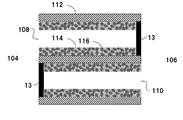
- the illustrated honeycomb structure 1 is disposed at the outermost peripheral wall 102 located at the outermost periphery and inside the outer peripheral wall 102, and extends from a first end face 104 (an inflow end face which is an end face on the fluid inflow side) to a second end face 106 ( A plurality of cells (in the figure, a plurality of first cells 108 having plugging portions that are open at the first end surface 104 and protrude from the second end surface 106) and extend in parallel between the fluid outflow end surfaces which are the end surfaces on the fluid outflow side.
- the illustrated honeycomb structure 1 includes a porous partition wall 112 for partitioning the first cell 108 and the second cell 110, and the first cell 108 and the second cell 110 alternate with the partition wall 112 interposed therebetween. And both end faces form a checkered pattern.
- all the first cells 108 are adjacent to the second cells 110, and all the second cells 110 are adjacent to the first cells 108.
- a plurality of cells need not necessarily have plugging portions.
- the number, arrangement, shape, and the like of the cells 108 and 110, the thickness of the partition 112, and the like are not limited, and can be appropriately designed as needed.
- the material of the honeycomb structure there is no particular limitation on the material of the honeycomb structure, but since it is necessary to be a porous body having a large number of pores, it is usually formed of a ceramic material, for example, cordierite, silicon carbide, titanate, and the like. Examples include aluminum, silicon nitride, mullite, alumina, a silicon-silicon carbide composite material, and a silicon-carbide composite material, particularly a silicon-silicon carbide composite material or a sintered body containing silicon carbide as a main component.
- silicon carbide-based means that the honeycomb structure contains silicon carbide in an amount of 50% by mass or more of the entire honeycomb structure.
- the honeycomb structure contains the silicon-silicon carbide composite material as a main component means that the honeycomb structure contains the silicon-silicon carbide composite material (total mass) at 90% by mass or more of the entire honeycomb structure.
- the silicon-silicon carbide composite material contains silicon carbide particles as an aggregate and silicon as a binder for binding the silicon carbide particles, and a plurality of silicon carbide particles are interposed between the silicon carbide particles. It is preferable that they are bonded by silicon so as to form pores.
- the fact that the honeycomb structure contains silicon carbide as a main component means that the honeycomb structure 1 contains silicon carbide (total mass) of 90% by mass or more of the entire honeycomb structure.
- the honeycomb structure is formed of at least one ceramic material selected from the group consisting of cordierite, silicon carbide, aluminum titanate, silicon nitride, mullite, and alumina.
- the cell shape of the honeycomb structure is not particularly limited, but is preferably a polygon such as a triangle, a quadrangle, a pentagon, a hexagon, or an octagon, a circle, or an ellipse in a cross section orthogonal to the central axis, and other irregular shapes. It may be.
- the outer shape of the honeycomb structure is not particularly limited, but the end surface is a circular column (cylindrical shape), the end surface is an oval-shaped column, and the end surface is a polygon (square, pentagon, hexagon, heptagon, octagon, etc.). )).
- the size of the honeycomb structure is not particularly limited, but the length in the central axis direction is preferably 40 to 500 mm. Further, for example, when the outer shape of the honeycomb structure is cylindrical, it is preferable that the end face has a radius of 50 to 500 mm.
- the thickness of the partition walls of the honeycomb structure is preferably 0.20 to 0.50 mm, and more preferably 0.25 to 0.45 mm from the viewpoint of ease of production. For example, when the thickness is 0.20 mm or more, the strength of the honeycomb structure is further improved. When the thickness is 0.50 mm or less, the pressure loss can be further reduced when the honeycomb structure is used as a filter. Note that the thickness of the partition wall is an average value measured by a method of observing a cross section in the central axis direction with a microscope.
- the porosity of the partition walls constituting the honeycomb structure is preferably 30 to 70%, and more preferably 40 to 65% from the viewpoint of easy production. When it is 30% or more, the pressure loss tends to decrease, and when it is 70% or less, the strength of the honeycomb structure can be maintained.
- the average pore diameter of the porous partition wall is preferably 5 to 30 ⁇ m, more preferably 10 to 25 ⁇ m. When it is 5 ⁇ m or more, when used as a filter, pressure loss can be reduced, and when it is 30 ⁇ m or less, the strength of the honeycomb structure can be maintained.
- the terms “average pore diameter” and “porosity” mean the average pore diameter and porosity measured by the mercury intrusion method.
- the cell density of the honeycomb structure is not particularly limited, but is preferably in the range of 5 to 63 cells / cm 2 , and more preferably in the range of 31 to 54 cells / cm 2 .
- Such a honeycomb structure is formed from a clay containing a ceramic raw material into a honeycomb shape having partition walls that penetrate from one end face to the other end face and form a plurality of cells that serve as fluid flow paths.
- the honeycomb formed body is formed by forming a honeycomb formed body, drying the honeycomb formed body, and then firing the formed body.
- the outer peripheral wall may be used as the outer peripheral wall by extruding the outer peripheral wall integrally with the honeycomb structure portion, or after forming or firing.
- the outer periphery of the honeycomb formed body may be ground to have a predetermined shape, and the outer periphery may be coated by applying a coating material to the honeycomb structure having the outer periphery ground.
- a honeycomb structure having an outer periphery is used without grinding the outermost periphery of the honeycomb structure, and the outer peripheral surface of the honeycomb structure having the outer periphery (that is, the honeycomb)
- the above-mentioned coating material may be further applied to the outer periphery of the outer periphery of the structure to form an outer periphery coating.
- an outer peripheral wall having a two-layer structure located at the outermost periphery where an outer peripheral coating made of a coating material is laminated is formed.
- the outer peripheral wall may be extruded integrally with the honeycomb structure, fired as it is, and used as the outer peripheral wall without processing the outer periphery.
- the composition of the coating material is not particularly limited, and various known coating materials can be appropriately used.
- the coating material may further contain colloidal silica, an organic binder, clay and the like.
- the organic binder is preferably used in an amount of 0.05 to 0.5% by mass, more preferably 0.1 to 0.2% by mass.
- the clay is preferably used in an amount of 0.2 to 2.0% by mass, more preferably 0.4 to 0.8% by mass.
- the honeycomb structure is not limited to an integral honeycomb structure in which the partition walls are integrally formed.
- the honeycomb structure has a porous partition wall, and the partition wall has a flow of fluid.
- a honeycomb structure having a structure in which a plurality of column-shaped honeycomb segments in which a plurality of cells serving as roads are partitioned and formed via a bonding material layer is combined hereinafter, may be referred to as a “bonded honeycomb structure”). There may be.
- the honeycomb structure has a structure in which one open end of a predetermined cell among the plurality of cells and the other open end of the remaining cells are plugged with a plugged portion. Is also good.
- a honeycomb structure can be used as a filter for purifying exhaust gas (honeycomb filter).
- plugged portions may be provided after the outer peripheral coating is formed, or may be in a state before the outer peripheral coating is formed, that is, at a stage of manufacturing the honeycomb structure. It may be provided.
- a plugged portion one having the same configuration as that used as a plugged portion of a conventionally known honeycomb structure can be used.
- the honeycomb structure of the present embodiment may be one in which a catalyst is supported on at least one of the surface of the partition and the inside of the pores of the partition.
- the honeycomb structure of the present embodiment includes a catalyst carrier supporting a catalyst and a filter (for example, a diesel particulate filter) provided with plugging portions for purifying particulate matter (carbon fine particles) in exhaust gas. (Hereinafter, also referred to as “DPF”)).
- the type of the catalyst is not particularly limited, and can be appropriately selected depending on the purpose and use of the honeycomb structure.
- a noble metal-based catalyst or a catalyst other than these can be used.
- a noble metal-based catalyst a noble metal such as platinum (Pt), palladium (Pd), and rhodium (Rh) is supported on the pore surface of alumina, and a three-way catalyst including a co-catalyst such as ceria and zirconia; an oxidation catalyst;
- a NO x storage reduction catalyst containing an earth metal and platinum as nitrogen oxide (NO x ) storage components is exemplified.
- NO x selective reduction catalyst or the like containing copper substituted or iron-substituted zeolite is exemplified.
- the method for supporting the catalyst is not particularly limited, and can be performed according to the conventional method for supporting the catalyst on the honeycomb structure.
- Each of the fired honeycomb structures can be used as a honeycomb segment, and the side surfaces of the plurality of honeycomb segments can be joined together by a joining material and integrated to form a honeycomb structure in which the honeycomb segments are joined.
- the honeycomb structure in which the honeycomb segments are joined can be manufactured, for example, as follows. The bonding material is applied to the bonding surfaces (side surfaces) in a state where the bonding material adhesion preventing masks are attached to both end surfaces of each honeycomb segment.
- honeycomb segments are arranged adjacent to each other so that the side surfaces of the honeycomb segments face each other, and the adjacent honeycomb segments are press-bonded to each other and then dried by heating.
- the outer peripheral portion may be ground to a desired shape (for example, a columnar shape), coated with a coating material on the outer peripheral surface, and then dried by heating to form the outer peripheral wall.
- the material of the mask for preventing adhesion of the bonding material is not particularly limited.
- a synthetic resin such as polypropylene (PP), polyethylene terephthalate (PET), polyimide, or Teflon (registered trademark) can be suitably used.
- the mask preferably has an adhesive layer, and the material of the adhesive layer is an acrylic resin, a rubber-based (for example, rubber mainly composed of natural rubber or synthetic rubber), or a silicon-based resin. preferable.
- an adhesive film having a thickness of 20 to 50 ⁇ m can be suitably used.
- the bonding material for example, a material prepared by mixing a ceramic powder, a dispersion medium (for example, water, and the like), and, if necessary, additives such as a binder, a deflocculant, and a foamed resin can be used.
- a ceramic powder for example, a ceramic powder, a dispersion medium (for example, water, and the like), and, if necessary, additives such as a binder, a deflocculant, and a foamed resin
- the ceramics ceramics containing at least one selected from the group consisting of cordierite, mullite, zircon, aluminum titanate, silicon carbide, silicon nitride, zirconia, spinel, indialite, sapphirine, corundum, and titania And more preferably the same material as the honeycomb structure.
- the binder include polyvinyl alcohol, methylcellulose, and CMC (carboxymethylcellulose).
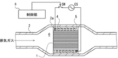
- FIG. 2 is a schematic view of an exhaust gas flow path of an exhaust gas purifying device in which a honeycomb structure is incorporated.
- the flow path of the exhaust gas is defined by the metal pipe 2.
- An exhaust gas purifying device 6 is arranged at the enlarged diameter portion 2a of the metal tube 2.
- the exhaust gas purifying device 6 includes a honeycomb structure 1, a coil wiring 4 helically circling the outer periphery of the honeycomb structure 1, and a fixing member 5 for fixing the coil wiring 4 in the metal tube 2.
- the honeycomb structure 1 may support a catalyst.
- the coil wiring 4 is spirally wound around the outer periphery of the honeycomb structure 1.
- a form in which two or more coil wirings 4 are used is also assumed.
- An AC current supplied from the AC power supply CS flows through the coil wiring 4 in response to the ON of the switch SW, and as a result, a periodically changing magnetic field is generated around the coil wiring 4.
- the ON / OFF of the switch SW is controlled by the control unit 3.
- the control unit 3 turns on the switch SW in synchronization with the start of the engine, and allows an alternating current to flow through the coil wiring 4.
- a mode in which the control unit 3 turns on the switch SW regardless of the start of the engine (for example, in response to the operation of a heating switch pressed by a driver) is also assumed.
- the fixing member 5 is a heat-resistant member, and is provided for fixing the honeycomb structure 1 supporting the catalyst and the coil wiring 4 in the metal tube 2.
- the input power applied by the exhaust gas purification device is preferably in the range of 1 kW to 10 kW from the viewpoint of heating performance.
- the heating frequency is preferably in the range of 10 to 500 kHz.
- the temperature of the honeycomb structure 1 rises according to a change in a magnetic field according to an alternating current flowing through the coil wiring 4. As a result, carbon fine particles and the like collected by the honeycomb structure 1 burn.
- increasing the temperature of the honeycomb structure 1 increases the temperature of the catalyst supported by the catalyst carrier included in the honeycomb structure 1 and promotes the catalytic reaction.
- carbon monoxide (CO), nitrided oxide (NO x ), and hydrocarbon (CH) are oxidized or reduced to carbon dioxide (CO 2 ), nitrogen (N 2 ), and water (H 2 O). You.
- FIG. 6 is a schematic diagram of an exhaust system 20 including an exhaust silencing muffler 22 and an exhaust gas purifying device 26 provided in the exhaust silencing muffler 22.
- a muffler is provided in the exhaust muffler 22.
- the silencer may include a plurality of silencers such as a main silencer and a sub silencer.
- the exhaust gas purifying device 26 has the honeycomb structure 1 incorporated therein, and includes a coil wiring that spirals around the outer periphery of the honeycomb structure 1 and a fixing member for fixing the coil wiring in the exhaust gas flow path.
- the exhaust system 20 includes an exhaust pipe 21 serving as a flow path for exhaust gas supplied to the exhaust muffler 22 or a flow path for exhaust gas discharged from the exhaust muffler 22.
- FIG. 7 shows a schematic diagram of an exhaust gas purifying device 26 provided in the exhaust muffler 22 of the exhaust system 20.
- FIG. 7 is an enlarged view of a part of the vicinity of the coil wiring 24 embedded in the holding mat 25 of the exhaust gas purifying device 26 for explaining the noise reduction function.
- the deposition flow rate of the gas is smaller, and the speed of the gas passing through the partition walls of the honeycomb structure 1 can be reduced. For this reason, it is preferable to dispose the honeycomb structure 1 on the downstream side of the exhaust system 20 as far as possible from the viewpoint of securing soot collection efficiency.
- the honeycomb structure 1 be provided inside the main muffler located at the most downstream of the exhaust system 20 or the auxiliary muffler at the preceding stage.
- the conventional honeycomb structure is mounted in the exhaust muffler, only the small pores of the partition walls of the honeycomb structure are blocked with liquid water by capillary action due to condensation of water.
- the soot collection efficiency is deteriorated due to a high-speed gas flowing into the large pores, and a problem that soot cannot be regenerated because the exhaust gas temperature is too low.
- honeycomb structure 1 can evaporate and remove water by electromagnetic induction heating, it is possible to maintain a high soot collection efficiency and to heat the soot to a temperature required for soot regeneration at the time of soot regeneration. can do. For this reason, the problem that soot cannot be reproduced hardly occurs.
- the honeycomb structure 1 has pressure loss factors such as gas expansion and contraction, gas passage through a porous body, and cell passages, and these have a sound deadening effect. For this reason, it is possible to partially replace the muffling function in the muffler.
- a method of confining the high frequency sound near the outer periphery of the exhaust muffler 22 and attenuating the high frequency sound as shown in FIG. 7 is more effective.
- the cells near the outer periphery of the honeycomb structure have a structure in which both ends are sealed, and sound waves are hardly leaked in the axial direction.
- sound waves transmitted through the honeycomb structure 1 in the exhaust muffler 22 of the exhaust system 20 are transmitted through the partition walls 112 of the honeycomb structure 1 and the gap between the partition walls 112, and are attenuated by the partition walls.
- the honeycomb structure may be one in which unsealed cells penetrate, or a wall flow type filter in which both ends are alternately plugged. From the viewpoint of the noise reduction effect, a wall flow type filter in which both ends are alternately plugged is more preferable.
- the honeycomb structure 1 has a surface layer 114 on at least a part of the surface of the partition wall 112.
- the surface layer 114 includes magnetic particles 116 and has air permeability.
- having air permeability means that the permeability of the surface layer is 1.0 ⁇ 10 ⁇ 13 m 2 or more. From the viewpoint of further reducing the pressure loss, the permeability is preferably 1.0 ⁇ 10 ⁇ 12 m 2 or more. When the surface layer has air permeability, pressure loss caused by the surface layer can be suppressed.
- permeability refers to a physical property value calculated by the following equation (1), and is a value that serves as an index indicating a passage resistance when a predetermined gas passes through the object (partition).
- C is the permeability (m 2 )
- F is the gas flow rate (cm 3 / s)
- T is the sample thickness (cm)
- V is the gas viscosity (dynes ⁇ sec / cm 2 ).
- D indicates the sample diameter (cm)
- P indicates the gas pressure (PSI).
- a partition with a surface layer is cut out, the permeability is measured in a state with the surface layer, and then the permeability is measured with the surface layer cut off, and the surface layer and the partition base are measured.
- the permeability of the surface layer is calculated from the ratio of the thickness of the material and the measurement results of the permeability.
- the surface layer 114 includes the magnetic particles 116, the honeycomb structure 1 is heated by electromagnetic induction. Therefore, it is not necessary to supply electricity to the honeycomb structure 1 itself, and the occurrence of a short circuit can be suppressed even in an environment where condensed water is generated. In addition, a short circuit due to carbon deposition can be suppressed. To obtain this effect, the surface layer 114 needs to be provided on at least a part of the surface of the partition wall 112 of the honeycomb structure 1. In FIG. 3, both surfaces of the partition 112 are covered with the surface layer 114, but it is not necessarily formed on both surfaces. For example, the surface layer 114 is formed only on the surface on which the first cell 108 or the second cell 110 is formed. May be. That is, the surface layer 114 preferably covers at least one side of the partition 112.
- the surface layer 114 containing the magnetic particles 116 may be provided only in a portion where the soot regeneration effect is most easily exhibited. For example, the initial soot accumulation of a normal gasoline particulate occurs more frequently near the outlet of the honeycomb structure 1. Therefore, the surface layer 114 may be provided only in the downstream region of the honeycomb structure 1. According to such a configuration, only the portion where a large amount of soot is deposited is heated, so that the soot can be burned efficiently and the power consumption can be suppressed. In particular, it is suitable for regenerating soot in a state where gas does not flow through the honeycomb structure 1 such as when the vehicle is stopped.
- the surface layer 114 may be provided only at a central portion in a gas flow direction (axial direction of the honeycomb structure 1). By heating the central portion in the gas flow direction, the soot in the downstream region of the honeycomb structure 1 having a large amount of soot deposition can be effectively burned by utilizing the effect of heat transfer by the gas.
- the magnetic particles 116 are preferably formed of a magnetic material having a Curie temperature.
- the Curie temperature of the magnetic particles 116 is not particularly limited, but is preferably higher than 450 ° C. More preferably, it is 800 ° C. or higher. If the Curie temperature of the magnetic particles 116 exceeds 450 ° C., it becomes possible to reach a honeycomb temperature sufficient to raise the catalyst temperature to the catalyst activation temperature or higher.
- Fe includes, for example, Cr 18% Fe (Cr 18 mass% stainless steel), Fe, Fe—Cr—Al alloy, Fe—Cr—Si alloy, Fe—Si—Ti alloy, Co-Fe alloy, Co-Fe-V alloy, Co-Ni-Fe alloy, Fe-Co-Nb alloy, Fe-Co-Cr alloy, Fe-Co-Cr-Mo alloy, Fe-Co-Cr-Mo- Al alloy, FeOFe 2 O 3, NiOFe 2 O 3, CuOFe 2 O 3, MgOFe 2 O 3, MnBi, Ni, MnSb, there is MnOFe 2 O 3, Y 3 Fe 5 O 12 and the like.
- Magnetic particles having a Curie temperature of 800 ° C.
- Co—Fe alloys Co—Fe—V alloys, Co—Ni—Fe alloys, Fe—Co—Nb alloys, Fe—Co—Cr alloys, and Fe—Co— alloys.
- Cr-Mo alloy, Fe-Co-Cr-Mo-Al alloy and the like can be mentioned.
- the specific composition is as follows: balance Co-20 mass% Fe, balance Co-25 mass% Ni-4 mass% Fe, balance Fe-15 to 35 mass% Co, balance Fe-17 mass% Co-2 mass% Cr -1 mass% Mo, balance Fe-49 mass% Co-2 mass% V, balance Fe-18 mass% Co-10 mass% Cr-2 mass% Mo-1 mass% Al, balance Fe-27 mass% Co- 1 mass% Nb, balance Fe-20 mass% Co-1 mass% Cr-2 mass% V, balance Fe-35 mass% Co-1 mass% Cr, pure cobalt, pure iron, electromagnetic soft iron, balance Fe-0. 1 to 0.5% by mass Mn. It is desirable to use a metal containing Co having a high Curie temperature.
- the porosity of the surface layer 114 is preferably 50% or more, more preferably 60% or more, and even more preferably 70% or more. By having a porosity of 50% or more, pressure loss can be suppressed. However, if the porosity is too high, the surface layer becomes brittle and easily peels off. Therefore, it is preferably 90% or less.
- the porosity of the surface layer 114 is calculated from the shaved mass and the mercury porosi curve.
- the porosity of the surface layer may be calculated from the area ratio of the void portion and the solid portion by performing SEM image capturing and analyzing the image of the surface layer portion.
- the average pore diameter of the surface layer 114 is preferably 10 ⁇ m or less, more preferably 5 ⁇ m or less, further preferably 4 ⁇ m or less, and particularly preferably 3 ⁇ m or less. By setting the average pore diameter to 10 ⁇ m or less, high particle collection efficiency can be achieved. However, if the average pore diameter of the surface layer 114 is too small, the pressure loss will increase.
- the mercury porosi curve (pore volume frequency) and the surface layer of the substrate on which the surface layer is formed are represented by a peak value measured by a mercury porosimeter.
- the difference from the mercury porosi curve of only the substrate obtained by shaving off only 114 is taken as the mercury porosi curve of the surface layer, and the peak is taken as the average pore diameter.
- a SEM image of a cross section of the honeycomb structure is taken, and image analysis of the surface layer portion is performed to binarize the void portion and the solid portion, and randomly select 20 or more voids and average the inscribed circle thereof.
- the average pore diameter may be used.
- the weight average particle diameter of the magnetic particles 116 in the surface layer 114 is preferably 20 ⁇ m or less. By setting the weight average particle diameter to 20 ⁇ m or less, it is possible to keep the average pore diameter, thickness, and porosity of the target surface layer in a range that satisfies all of them, in combination with other controllable design factors. Becomes The lower limit of the weight average particle diameter of the magnetic particles 116 is not particularly limited, but may be, for example, 0.5 ⁇ m or more. The weight average particle diameter is measured by a laser diffraction type particle size distribution analyzer.
- the thickness of the surface layer 114 and the thickness of the partition 112 are substantially the same, but the thickness of the surface layer 114 is not particularly limited. However, in order to obtain the effect of the surface layer 114 more remarkably, the thickness of the surface layer 114 is preferably 10 ⁇ m or more. On the other hand, from the viewpoint of avoiding an increase in pressure loss, the thickness of the surface layer 114 is preferably 80 ⁇ m or less. The thickness of the surface layer 114 is more preferably 50 ⁇ m or less.
- a honeycomb structure on which the surface layer is formed is cut in a direction perpendicular to the direction in which the cells extend, and the thickness of the surface layer is measured from the cross section. The average of the thickness measurements can be taken.
- the shortest diameter d of the magnetic particles 116 is 0.1 to 5 ⁇ m and the longest diameter of the magnetic particles 116 is L ⁇ m.
- the shortest diameter d is defined as the shortest diameter of a particle, which is the largest one among the line segments orthogonal to the longest diameter of the particle for 50 particles by image analysis from an SEM photographed image, and this is averaged by the number of particles. Thus, the shortest diameter d can be obtained.
- the length is obtained by averaging the longest diameters of 50 or more particles in the SEM image by the number of particles, thereby obtaining the longest diameter L.
- the magnetic particles 116 are needle-like or scale-like. Acicular refers to L / d ⁇ 5.
- the scaly shape means a ratio L / t> 5 between the thickness t of the magnetic particles 116 and the longest diameter L.
- the thickness t of the magnetic particles 116 can be obtained by measuring the thickness of the portion where the thickness of the particle is the largest for 50 particles by image analysis from an SEM photographed image, and averaging this by the number of particles.
- a stress relaxation layer having a thermal expansion coefficient between the surface layer 114 and the partition wall 112 between the surface layer 114 and the partition 112. Thereby, it is possible to prevent the occurrence of cracks or the like due to the difference in the thermal expansion coefficient between the surface layer 114 and the partition 112, thereby improving the thermal shock resistance.
- the composition of the stress relaxation layer is not particularly limited, for example, a low expansion glass layer, an alumina layer, a silica layer, and a ceria layer can be suitably used.
- a honeycomb structure having a porous partition wall and a plurality of cells defined by the partition wall is manufactured.
- a cordierite forming raw material is prepared as a clay material.
- the cordierite-forming raw material contains a silica source component, a magnesia source component, an alumina source component, and the like in order to mix each component so as to have a theoretical composition of cordierite crystals.
- quartz and fused silica are preferably used as the silica source component, and the particle size of the silica source component is preferably 100 to 150 ⁇ m.
- magnesia source component examples include talc and magnesite. Of these, talc is preferred. Preferably, talc is contained in the cordierite-forming raw material in an amount of 37 to 43% by mass.
- the particle size (average particle size) of talc is preferably from 5 to 50 ⁇ m, more preferably from 10 to 40 ⁇ m.
- the magnesia (MgO) source component may contain Fe 2 O 3 , CaO, Na 2 O, K 2 O, etc. as impurities.
- alumina source component those containing at least one of aluminum oxide and aluminum hydroxide are preferable in that they contain few impurities.
- aluminum hydroxide is preferably contained in an amount of 10 to 30% by mass, and aluminum oxide is preferably contained in an amount of 0 to 20% by mass.
- a clay material (additive) to be added to the cordierite-forming raw material is prepared.
- At least a binder and a pore former are used as additives.
- a dispersant or a surfactant can be used.
- a substance which can be oxidized and removed by reacting with oxygen at a temperature lower than the firing temperature of cordierite, a low-melting point reactive substance having a melting point at a temperature lower than the firing temperature of cordierite, or the like can be used.
- the substance that can be removed by oxidation include resin (particularly, particulate resin), graphite (particularly, particulate graphite), and the like.
- the low-melting point reactant include at least one metal selected from the group consisting of iron, copper, zinc, lead, aluminum, and nickel, and alloys containing these metals as main components (for example, in the case of iron, carbon steel Or cast iron, stainless steel) or an alloy containing two or more kinds as main components.
- the low-melting-point reactant is preferably a powdery or fibrous iron alloy. Further, the particle diameter or fiber diameter (average diameter) is preferably from 10 to 200 ⁇ m. Examples of the shape of the low-melting-point reactant include a sphere, a convoluted diamond, and a confetti, and these shapes are preferable because the shape of the pores can be easily controlled.
- binder examples include hydroxypropyl methylcellulose, methylcellulose, hydroxyethylcellulose, carboxymethylcellulose, polyvinyl alcohol and the like.
- dispersant examples include dextrin and polyalcohol.
- surfactant examples include fatty acid soap.
- the additives may be used alone or in combination of two or more.
- the cordierite-forming raw material 3 to 8 parts by mass of the binder, 3 to 40 parts by mass of the pore-forming agent, 0.1 to 2 parts by mass of the dispersant, and 10 to 40 parts by mass of water.
- the kneaded materials are kneaded to prepare a kneaded material.
- the prepared clay is formed into a honeycomb shape by an extrusion molding method, an injection molding method, a press molding method, or the like, to obtain a raw honeycomb molded body. It is preferable to employ an extrusion molding method because continuous molding is easy and, for example, cordierite crystals can be oriented.
- the extrusion method can be performed using a device such as a vacuum kneader, a ram type extruder, a twin screw type continuous extruder.
- the honeycomb formed body is dried and adjusted to a predetermined size to obtain a dried honeycomb body. Drying of the honeycomb formed body can be performed by hot air drying, microwave drying, dielectric drying, reduced pressure drying, vacuum drying, freeze drying, or the like. In addition, since it is possible to dry the whole quickly and uniformly, it is preferable to perform the drying by combining hot air drying and microwave drying or dielectric drying.
- the plugging material As the material of the plugging portion (plugging slurry), the same material for the clay as that of the partition wall (dried honeycomb body) may be used, or a different material may be used. Specifically, it is obtained by mixing a ceramic raw material, a surfactant, and water, adding a sintering aid, a pore-forming agent, and the like, if necessary, forming a slurry, and kneading using a mixer or the like. be able to.
- a mask is applied to a part of the cell opening on one end face of the dried honeycomb body, and the end face is immersed in a storage container in which the plugging slurry is stored, so that the cell is not masked. Fill the plugging slurry.
- a mask is applied to a part of the cell opening on the other end face of the dried honeycomb body, and the end face is immersed in a storage container in which the plugging slurry is stored, and the cell without the mask is masked. Is filled with a plugging slurry.
- the honeycomb structure is dried and fired to obtain a honeycomb structure having plugged portions.
- the drying conditions the same conditions as those for drying the honeycomb formed body can be adopted.
- the calcination may be usually performed at a temperature of 1410 to 1440 ° C. for 3 to 15 hours under an air atmosphere.
- the outer peripheral surface may be ground to remove the outer peripheral wall.
- a coating material is applied to the outer periphery of the honeycomb structure from which the outer peripheral wall has been removed to form an outer peripheral coating.
- the outer peripheral surface is ground, a part of the outer peripheral wall may be removed by grinding, and the outer peripheral coating may be formed on the part by a coating material.
- a coating material for example, it can be prepared using a two-axis rotating vertical mixer.
- the coating material may further contain colloidal silica, an organic binder, clay and the like.
- the organic binder is preferably used in an amount of 0.05 to 0.5% by mass, more preferably 0.1 to 0.2% by mass.
- the clay is preferably used in an amount of 0.2 to 2.0% by mass, more preferably 0.4 to 0.8% by mass.
- a coating material is applied to the outer peripheral surface of the honeycomb structure manufactured earlier, and the applied coating material is dried to form an outer peripheral coating.
- the honeycomb structure is placed on a rotating table and rotated, and the coating material is discharged from the blade-shaped coating nozzle while the coating nozzle is arranged along the outer peripheral portion of the honeycomb structure.
- a method of applying by pressing is given. With this configuration, the coating material can be applied with a uniform thickness. Further, the surface roughness of the formed outer peripheral coating is reduced, and the outer peripheral coating having excellent appearance and being hardly damaged by thermal shock can be formed.
- the outer peripheral coating In the case where the outer peripheral surface of the honeycomb structure is ground and the outer peripheral wall is removed, a coating material is applied to the entire outer peripheral surface of the honeycomb structure to form an outer peripheral coating.
- the outer peripheral coating may be formed by partially applying a coating material, Of course, the outer peripheral coating may be formed by applying a coating material to the entire outer peripheral surface of the honeycomb structure.
- the method of drying the applied coating material that is, the undried outer peripheral coating.
- the moisture in the coating material can be reduced.
- a method of removing moisture and organic substances by holding the same at 600 ° C. for 1 hour or more in an electric furnace can be preferably used.
- the openings of the cells of the honeycomb structure are not sealed in advance, the openings of the cells may be plugged after the outer peripheral coating is formed.
- the obtained honeycomb structure is irradiated with a laser beam on the outer peripheral surface of the obtained honeycomb structure because the silicon carbide powder contained in the coating material is colored by irradiating the outer peripheral surface with a laser. Then, product information or the like may be printed (marked).
- the laser beam used for laser marking include a carbon dioxide (CO 2 ) laser, a YAG laser, and a YVO4 laser.
- the conditions of the laser for irradiating the laser beam can be appropriately selected according to the type of laser to be used. For example, when a CO 2 laser is used, the output is 15 to 25 W and the scan speed is 400 to 600 mm /. Marking with s is preferred. By performing such marking, the irradiated portion is colored so as to exhibit a dark color such as black to green, and the contrast with the non-irradiated portion is extremely good.
- the printed portion does not deteriorate even after printing by the laser, and the printed image can be read well even after the catalyst is supported.
- the method for supporting the catalyst is not particularly limited, and it can be carried out according to the method for supporting the catalyst used in the conventional method for manufacturing a honeycomb structure.
- At least a part of the surface of the partition wall of the honeycomb structure is formed with a gas-permeable and air-permeable surface layer.
- the surface layer preferably covers at least one surface of the partition.
- a slurry containing magnetic particles and a binder mainly composed of metal or glass is poured into cells of the honeycomb structure to form a coating film, and the coating film is formed by melting point of metal or softening point of glass.
- -A slurry containing magnetic particles and an adhesive material containing silica or alumina as a main component is poured into cells of the honeycomb structure to form a coating film, and the coating film is heated to solidify the silica or alumina. To form a surface layer. Flowing a gas containing magnetic particles and the binder or the adhesive material into the cells of the honeycomb structure, or flowing a gas containing only magnetic particles into the cells of the honeycomb structure to form a coating film And a method of heating the coating film to form a surface layer.
- the slurry may be circulated in the cells of the honeycomb structure, or the slurry may be immersed in the cells of the honeycomb structure.
- a binder containing metal or glass as a main component, it is necessary to once melt or soften the honeycomb substrate at a temperature lower than the allowable temperature limit during the production, so that the temperature is higher than the melting point or the softening point of the binder.
- the coating is heated.
- the maximum temperature reaches about 700 ° C., it is more preferable to use a metal or glass having a melting point or a softening point higher than this temperature.
- the specific melting point or softening point is, for example, 800 to 1200 ° C.
- an adhesive material containing silica or alumina as a main component it is preferable that the adhesive material can be solidified by heating and drying during production.
- a material that can solidify the adhesive material by heating and drying include a colloidal dispersion of silica or alumina, and a colloidal dispersion containing silica and alumina may be used.
- the maximum temperature of the use environment of the honeycomb structure reaches about 700 ° C., it is more preferable to use silica or alumina having a heat-resistant temperature equal to or higher than this temperature.
- a suction jig is attached to the downstream side of the honeycomb structure, and excess water is removed by suction from the other open end downstream of the honeycomb structure to form a coating film.
- the conditions for heat treatment of this coating film it is preferable to heat the coating at a temperature of 800 to 1200 ° C. for 0.5 to 3 hours.
- the step of pouring the slurry into the cells may be performed at the stage of honeycomb forming and drying.
- the honeycomb structure before the surface layer is formed is dried, and in the firing step of the honeycomb structure, the magnetic particles are fixed to the adhesive material to form the surface layer.
- the magnetic particles are coated in advance with a binder mainly composed of metal or glass. Further, a step of forming composite particles containing the magnetic particles and the binder may be provided.
- the slurry can be obtained, for example, by mixing the magnetic particles, the adhesive material or the binder, the organic binder, and water or alcohol. Further, an oil or fat and a surfactant may be further added to the slurry, mixed and emulsified.
- the slurry may be mixed with a pore-forming agent for controlling the porosity of the surface layer.
- a pore-forming agent for example, resin particles, starch particles, carbon particles and the like having a particle size of 0.5 ⁇ m to 10 ⁇ m can be used.
- a gas containing magnetic particles is supplied in a cell at 0.005 to 0.4 liter / cm 2 .
- the magnetic particles in a floating state are deposited on the surface of the partition wall.
- the magnetic particles are fused and fixed to the surface of the partition wall by, for example, a heat treatment at 800 to 1200 ° C. for 0.5 to 3 hours to form a surface layer.
- a gas containing only magnetic particles is flowed into a cell of the honeycomb structure
- a gas containing magnetic particles is blown into the cell at a rate of 0.005 to 0.4 liter / cm 2 to form a floating state.
- the magnetic particles are deposited on the surface of the partition walls, and then heat-treated at 1280 to 1330 ° C. for 0.5 to 3 hours to fuse and fix the magnetic particles to the surface of the partition walls.
- the organic binder may be mixed with the slurry or gas. Good.
- the coating film can be temporarily fixed at a stage before the step of forming the surface layer by heating.
- the organic binder a material which is oxidized and removed in an oxidizing atmosphere at a temperature lower than the temperature of the step of forming the surface layer by heating, that is, 800 ° C. or lower is preferable. Further, it is preferable to use the same binder as a binder used as a pore-forming agent when manufacturing a honeycomb structure.
- ⁇ Water was used as a dispersion medium, coke having an average particle diameter of 10 ⁇ m was used as a pore-forming agent, hydroxypropylmethylcellulose was used as an organic binder, and ethylene glycol was used as a dispersant.
- the kneaded material was extruded using a predetermined mold to obtain a honeycomb formed body having a square cell shape and an overall columnar (cylindrical) shape.
- the honeycomb formed body was dried with a microwave drier, and further completely dried with a hot-air drier. Then, both end faces were cut and adjusted to predetermined dimensions to obtain a honeycomb dried body.
- a mask is alternately applied in a checkered pattern to the cell opening on one end face of the dried honeycomb body, and the end on the side on which the mask is applied is immersed in a plugging slurry containing a cordierite forming raw material, Plugging portions alternately arranged in a checkered pattern were formed.
- a mask was applied to the cell plugged at one end, and a plugged portion was formed in the same manner as the plugged portion was formed at the one end. Thereafter, it was dried with a hot air drier and further baked at 1410 to 1440 ° C. for 5 hours to obtain a plugged honeycomb structure (honeycomb carrier).
- Example 1 With respect to the honeycomb structure manufactured by the above procedure, from one end face side, magnetic particles, resin particles having a weight average particle diameter of 3 ⁇ m, and glass mainly containing silica having a weight average particle diameter of 5 ⁇ m as a binder are used. Were mixed at a mass ratio of 80:10:10. This powder was placed in a stream of air to flow through the honeycomb structure, and was deposited on the surface of the partition wall to form a coating film. This coating film is subjected to a heat treatment at 950 ° C.
- This emulsified raw material was atomized by spraying, and was sucked together with air from the end of the honeycomb structure, thereby being deposited on the partition wall surface and dried to form a coating film. Thereafter, the organic binder was burned off by heat treatment at 600 ° C. for 1 hour in the air, and silica or alumina was solidified by heat treatment at 1000 ° C. for 1 hour in the air to form a surface layer.
- Example 4 With the honeycomb structure, one opening end, which is the inlet end face, facing up, a slurry pool for storing slurry is attached to the top, and the slurry is used for forming a surface layer (slurry (magnetic particles as aggregate, magnetic particles as binding particles) Glass powder) containing SiO 2 , Al 2 O 3 and MgO as main components. Then, after the slurry was infiltrated into the honeycomb structure, the slurry was sucked from the other open end downstream of the honeycomb structure to remove excess water, thereby forming a coating film. Thereafter, the coating film was dried and bonded at 950 ° C. at a temperature equal to or higher than the softening point of the glass powder to form a surface layer.
- slurry magnetic particles as aggregate, magnetic particles as binding particles
- Example 5 Dissolve 0.5 parts by mass of carboxymethylcellulose as an organic binder in 95 parts by mass of water, and in the aqueous solution thereof, aggregate particles of magnetic material particles having a shortest diameter d of 10 ⁇ m and a longest diameter L of 10 ⁇ m (18 mass% Cr stainless steel) 2.5 parts by mass, 5 parts by mass of a colloidal dispersion of glass powder (solid content: 40%) containing SiO 2 , Al 2 O 3 , and MgO as main components as a binder, and stirring in this order, are stirred to form a surface layer A slurry was obtained.
- a colloidal dispersion of glass powder solid content: 40%
- the honeycomb structure was immersed in the slurry for forming a surface layer, with the inlet side of the honeycomb structure facing down, the depth being equal to the depth of the outlet plugging material.
- the slurry was dip-coated on the inner surface of the inlet open cell.
- the coating film was heat-treated at 900 ° C. for 0.5 hour at a temperature not lower than the softening point of the glass powder to form a surface layer.
- Example 6 The magnetic particles having the longest diameter L10 ⁇ m were supplied to the honeycomb structure together with air, a pore former, and a glass powder mainly composed of silica as a binder, and these were deposited on the partition walls to form a coating film.
- the porosity and the average pore diameter of the surface layer can be controlled by appropriately setting the conditions such as the particle size and particle size distribution of the pore-forming agent, the amount added, and the amount of supplied air.
- starch was used as a pore-forming agent.
- the air permeation resistance is increased, and thus the supplied surface layer forming layer is formed.
- the deposition area of the raw material and the pore-forming agent can be controlled.
- the addition amount of the pore-forming agent is 3 parts by mass to 45 parts by mass
- the median diameter D50 of the pore-forming agent is 0.7 ⁇ m to 8.0 ⁇ m
- the sharpness index as the particle size distribution of the pore-forming agent is 0.1.
- the porosity and average pore diameter of the surface layer were changed by adjusting the flow rate of the fluid to 4 to 1.9 or the fluid flow rate to 2000 to 8000 L / min.
- the surface layer was formed by subjecting the coating film to a heat treatment at 950 ° C. for 1 hour in the air at a temperature not lower than the softening point of the glass powder.
- Example 7 A surface layer was formed on the honeycomb structure in the same manner as in Example 6, except that magnetic particles having the longest diameter L and the shortest diameter d shown in Table 1 were used.
- Example 9 A surface layer was formed on a honeycomb structure in the same manner as in Example 1 except that magnetic particles having the composition shown in Table 1 were used.
- Example 10 A surface layer was formed on the honeycomb structure in the same manner as in Example 6, except that flaky magnetic particles having a thickness of the longest diameter L and the shortest diameter d shown in Table 1 were used.
- Table 1 shows the characteristics of the honeycomb structure obtained in each example.
- the honeycomb structure of Example 7 was subjected to a heating test using an induction heating device.
- the input power was 4 kW
- the induction heating frequencies were 30 kHz, 85 kHz, and 350 kHz
- the heating performance of the honeycomb structures was compared.
- the induction heating frequency was 30 kHz or 85 kHz
- the coil was circulated around the outer periphery of the honeycomb structure for 6 turns
- the induction heating frequency was 350 kHz
- the coil was wrapped around the outer periphery of the honeycomb structure for 3 turns.
- the no-load inductance of the coil used at 30 kHz and 85 kHz is 2.5 ⁇ H
- the no-load inductance of the coil used at 350 kHz is 1.0 ⁇ H.
- FIG. 4 is a graph showing the relationship between time (second) and temperature (° C.) at each induction heating frequency of 30 kHz, 85 kHz, and 350 kHz in the heating test.
- Example 12 The honeycomb structure of Example 12 was similarly subjected to a heating test using an induction heating device.
- the input power was 4 kW
- the induction heating frequency was 350 kHz
- the heating performance of the honeycomb structure was compared with that of Example 7.
- the combination of the coil, the capacitor and the transformer in the 350 kHz induction heating test of the twelfth embodiment is the same as that of the seventh embodiment.
- FIG. 5 is a graph showing the relationship between time (second) and temperature (° C.) in the heating test. It was confirmed that the use of an alloy having a high Curie point (Fe-49Co-2V alloy) enables the honeycomb structure to be heated to 700 ° C. without the heat of oxidation of the catalyst.
- an alloy having a high Curie point Fe-49Co-2V alloy
Landscapes
- Chemical & Material Sciences (AREA)
- Engineering & Computer Science (AREA)
- Chemical Kinetics & Catalysis (AREA)
- Physics & Mathematics (AREA)
- Geometry (AREA)
- Mechanical Engineering (AREA)
- General Engineering & Computer Science (AREA)
- Combustion & Propulsion (AREA)
- Ceramic Engineering (AREA)
- Health & Medical Sciences (AREA)
- Toxicology (AREA)
- Thermal Sciences (AREA)
- Materials Engineering (AREA)
- Organic Chemistry (AREA)
- Structural Engineering (AREA)
- Life Sciences & Earth Sciences (AREA)
- Inorganic Chemistry (AREA)
- Geology (AREA)
- Filtering Materials (AREA)
- Processes For Solid Components From Exhaust (AREA)
- Exhaust Gas Treatment By Means Of Catalyst (AREA)
- Exhaust Gas After Treatment (AREA)
- Filtering Of Dispersed Particles In Gases (AREA)
- Porous Artificial Stone Or Porous Ceramic Products (AREA)
Abstract
L'invention concerne un corps structural en nid d'abeilles et un dispositif de purification de gaz d'échappement qui sont capables de brûler et d'éliminer des particules de carbone au moyen d'un chauffage électrique, qui peuvent être utilisés à une position où de l'eau de condensation est générée, qui sont exempts de court-circuits dus à l'eau de condensation ou au dépôt de carbone et qui présentent une faible perte de pression. Ce corps structural en nid d'abeilles présente une forme en colonne et comporte : des parois de séparation poreuses qui produisent des canaux d'écoulement pour un fluide et qui compartimentent et forment une pluralité de cellules s'étendant à partir d'une face d'extrémité de débit entrant, qui est la face d'extrémité disposée sur le côté débit entrant du fluide, à une face d'extrémité de débit sortant, qui est la face d'extrémité disposée sur le côté de débit sortant du fluide ; et une paroi périphérique externe disposée au niveau périphérique le plus à l'extérieur. Les parois de séparation comprennent chacune une couche superficielle qui est disposée sur au moins une portion de la surface de la paroi de séparation. La couche superficielle comprend des particules magnétiques et présente une perméabilité à l'air.
Priority Applications (4)
| Application Number | Priority Date | Filing Date | Title |
|---|---|---|---|
| DE112019004048.0T DE112019004048T5 (de) | 2018-08-10 | 2019-04-17 | Säulenförmige Wabenstruktur, Abgasreinigungsvorrichtung, Abgassystem und Verfahren zum Herstellen der Wabenstruktur |
| CN201980039861.1A CN112512993A (zh) | 2018-08-10 | 2019-04-17 | 蜂窝结构体、废气净化装置、排气系统及蜂窝结构体的制造方法 |
| JP2020536318A JP7423532B2 (ja) | 2018-08-10 | 2019-04-17 | ハニカム構造体、排気ガス浄化装置、排気システム及びハニカム構造体の製造方法 |
| US17/136,420 US11614011B2 (en) | 2018-08-10 | 2020-12-29 | Pillar shaped honeycomb structure, exhaust gas purifying device, exhaust system, and method for producing honeycomb structure |
Applications Claiming Priority (8)
| Application Number | Priority Date | Filing Date | Title |
|---|---|---|---|
| JP2018151973 | 2018-08-10 | ||
| JP2018-151974 | 2018-08-10 | ||
| JP2018-151973 | 2018-08-10 | ||
| JP2018151974 | 2018-08-10 | ||
| JP2018230370 | 2018-12-07 | ||
| JP2018-230370 | 2018-12-07 | ||
| JP2019022106 | 2019-02-08 | ||
| JP2019-022106 | 2019-02-08 |
Related Child Applications (1)
| Application Number | Title | Priority Date | Filing Date |
|---|---|---|---|
| US17/136,420 Continuation US11614011B2 (en) | 2018-08-10 | 2020-12-29 | Pillar shaped honeycomb structure, exhaust gas purifying device, exhaust system, and method for producing honeycomb structure |
Publications (1)
| Publication Number | Publication Date |
|---|---|
| WO2020031434A1 true WO2020031434A1 (fr) | 2020-02-13 |
Family
ID=69414688
Family Applications (1)
| Application Number | Title | Priority Date | Filing Date |
|---|---|---|---|
| PCT/JP2019/016520 WO2020031434A1 (fr) | 2018-08-10 | 2019-04-17 | Corps structural en nid d'abeilles, dispositif de purification de gaz d'échappement, système d'échappement et procédé de production d'un corps structural en nid d'abeilles |
Country Status (5)
| Country | Link |
|---|---|
| US (1) | US11614011B2 (fr) |
| JP (1) | JP7423532B2 (fr) |
| CN (1) | CN112512993A (fr) |
| DE (1) | DE112019004048T5 (fr) |
| WO (1) | WO2020031434A1 (fr) |
Cited By (4)
| Publication number | Priority date | Publication date | Assignee | Title |
|---|---|---|---|---|
| JPWO2021186792A1 (fr) * | 2020-03-19 | 2021-09-23 | ||
| JPWO2021230118A1 (fr) * | 2020-05-14 | 2021-11-18 | ||
| WO2022097341A1 (fr) * | 2020-11-04 | 2022-05-12 | 日本碍子株式会社 | Support de catalyseur et système de catalyseur de chauffage par induction |
| WO2022118531A1 (fr) * | 2020-12-02 | 2022-06-09 | 日本碍子株式会社 | Structure en nid d'abeilles, dispositif de purification de gaz d'échappement, et procédé de production de structure en nid d'abeilles |
Families Citing this family (3)
| Publication number | Priority date | Publication date | Assignee | Title |
|---|---|---|---|---|
| US20220389851A1 (en) * | 2021-06-02 | 2022-12-08 | Corning Incorporated | Segmented honeycomb heater |
| WO2024072781A1 (fr) * | 2022-09-30 | 2024-04-04 | Corning Incorporated | Procédés de fabrication de corps en nid d'abeilles avec des particules de traceur |
| CN117646896B (zh) * | 2024-01-29 | 2024-04-12 | 东北大学 | 一种污染物催化还原自换热装置、换热陶瓷球及燃烧器 |
Citations (6)
| Publication number | Priority date | Publication date | Assignee | Title |
|---|---|---|---|---|
| JPH11336534A (ja) * | 1998-05-26 | 1999-12-07 | Toyota Motor Corp | 内燃機関の誘導発熱式浄化装置 |
| JP2005207331A (ja) * | 2004-01-23 | 2005-08-04 | Hoei Kogyo Kk | 排気マフラ装置 |
| JP2005247605A (ja) * | 2004-03-02 | 2005-09-15 | Ngk Insulators Ltd | セラミック多孔質体及びその製造方法 |
| JP2006057584A (ja) * | 2004-08-23 | 2006-03-02 | Toyota Motor Corp | 排気ガス浄化用触媒 |
| JP2011224514A (ja) * | 2010-04-22 | 2011-11-10 | Ngk Insulators Ltd | 目封止ハニカム構造体の製造方法 |
| WO2016021186A1 (fr) * | 2014-08-07 | 2016-02-11 | 日本特殊陶業株式会社 | Élément de voie d'écoulement des gaz d'échappement, dispositif de purification des gaz d'échappement, procédé d'élévation de température correspondant et corps magnétique pour élément de voie d'écoulement des gaz d'échappement |
Family Cites Families (14)
| Publication number | Priority date | Publication date | Assignee | Title |
|---|---|---|---|---|
| US20030086839A1 (en) * | 2001-10-31 | 2003-05-08 | Rivin Eugeny I. | Catalytic reactors |
| EP2158956B1 (fr) | 2007-04-27 | 2014-10-08 | NGK Insulators, Ltd. | Filtre en nid d'abeilles |
| WO2009020835A2 (fr) * | 2007-08-03 | 2009-02-12 | Errcive, Inc. | Corps poreux et procédés |
| JP5261256B2 (ja) | 2009-03-30 | 2013-08-14 | 日本碍子株式会社 | 通電発熱用ハニカム体及びその製造方法 |
| JP4920752B2 (ja) | 2010-01-05 | 2012-04-18 | 日本碍子株式会社 | ハニカム構造体 |
| CN101879448B (zh) * | 2010-06-24 | 2012-05-23 | 天津大学 | 用于草酸酯加氢制乙二醇的规整结构催化剂及其制备方法 |
| US10132221B2 (en) | 2013-09-18 | 2018-11-20 | Advanced Technology Emission Solutions Inc. | Apparatus and method for gaseous emissions treatment with enhanced catalyst distribution |
| GB2520776A (en) * | 2013-12-02 | 2015-06-03 | Johnson Matthey Plc | Wall-flow filter comprising catalytic washcoat |
| JP6608598B2 (ja) * | 2015-02-26 | 2019-11-20 | Jfeスチール株式会社 | ハニカム構造体の製造方法 |
| JP6694301B2 (ja) * | 2016-03-23 | 2020-05-13 | 日本碍子株式会社 | 接合体及び接合体の製造方法 |
| JP2017186220A (ja) * | 2016-03-30 | 2017-10-12 | 日本碍子株式会社 | 遷移金属酸化物含有二酸化セリウム粒子 |
| CN109475855A (zh) * | 2016-05-11 | 2019-03-15 | 巴斯夫公司 | 适用于感应加热的含磁性材料的催化剂组合物 |
| CN107270311A (zh) * | 2017-06-09 | 2017-10-20 | 南通斐腾新材料科技有限公司 | 一种便携式催化燃烧床 |
| JP7122393B2 (ja) * | 2018-11-30 | 2022-08-19 | 日本碍子株式会社 | ハニカム構造体、排気ガス浄化装置及び排気システム |
-
2019
- 2019-04-17 CN CN201980039861.1A patent/CN112512993A/zh active Pending
- 2019-04-17 JP JP2020536318A patent/JP7423532B2/ja active Active
- 2019-04-17 DE DE112019004048.0T patent/DE112019004048T5/de active Pending
- 2019-04-17 WO PCT/JP2019/016520 patent/WO2020031434A1/fr active Application Filing
-
2020
- 2020-12-29 US US17/136,420 patent/US11614011B2/en active Active
Patent Citations (6)
| Publication number | Priority date | Publication date | Assignee | Title |
|---|---|---|---|---|
| JPH11336534A (ja) * | 1998-05-26 | 1999-12-07 | Toyota Motor Corp | 内燃機関の誘導発熱式浄化装置 |
| JP2005207331A (ja) * | 2004-01-23 | 2005-08-04 | Hoei Kogyo Kk | 排気マフラ装置 |
| JP2005247605A (ja) * | 2004-03-02 | 2005-09-15 | Ngk Insulators Ltd | セラミック多孔質体及びその製造方法 |
| JP2006057584A (ja) * | 2004-08-23 | 2006-03-02 | Toyota Motor Corp | 排気ガス浄化用触媒 |
| JP2011224514A (ja) * | 2010-04-22 | 2011-11-10 | Ngk Insulators Ltd | 目封止ハニカム構造体の製造方法 |
| WO2016021186A1 (fr) * | 2014-08-07 | 2016-02-11 | 日本特殊陶業株式会社 | Élément de voie d'écoulement des gaz d'échappement, dispositif de purification des gaz d'échappement, procédé d'élévation de température correspondant et corps magnétique pour élément de voie d'écoulement des gaz d'échappement |
Cited By (12)
| Publication number | Priority date | Publication date | Assignee | Title |
|---|---|---|---|---|
| JPWO2021186792A1 (fr) * | 2020-03-19 | 2021-09-23 | ||
| WO2021186792A1 (fr) * | 2020-03-19 | 2021-09-23 | 日本碍子株式会社 | Structure en nid d'abeilles, catalyseur de purification de gaz d'échappement et système de purification de gaz d'échappement |
| CN115209994A (zh) * | 2020-03-19 | 2022-10-18 | 日本碍子株式会社 | 蜂窝结构体、尾气净化催化器及尾气净化系统 |
| JP7438327B2 (ja) | 2020-03-19 | 2024-02-26 | 日本碍子株式会社 | ハニカム構造体、排気ガス浄化触媒及び排気ガス浄化システム |
| JPWO2021230118A1 (fr) * | 2020-05-14 | 2021-11-18 | ||
| WO2021230118A1 (fr) * | 2020-05-14 | 2021-11-18 | 日本碍子株式会社 | Structure en nid d'abeilles, et dispositif de purification de gaz d'échappement |
| CN115551614A (zh) * | 2020-05-14 | 2022-12-30 | 日本碍子株式会社 | 蜂窝结构体及尾气净化装置 |
| JP7368614B2 (ja) | 2020-05-14 | 2023-10-24 | 日本碍子株式会社 | ハニカム構造体及び排気ガス浄化装置 |
| WO2022097341A1 (fr) * | 2020-11-04 | 2022-05-12 | 日本碍子株式会社 | Support de catalyseur et système de catalyseur de chauffage par induction |
| JP7481485B2 (ja) | 2020-11-04 | 2024-05-10 | 日本碍子株式会社 | 触媒担体及び誘導加熱触媒システム |
| WO2022118531A1 (fr) * | 2020-12-02 | 2022-06-09 | 日本碍子株式会社 | Structure en nid d'abeilles, dispositif de purification de gaz d'échappement, et procédé de production de structure en nid d'abeilles |
| DE112021006255T5 (de) | 2020-12-02 | 2023-09-14 | Ngk Insulators, Ltd. | Wabenstruktur, abgasreinigungseinrichtung und herstellungsverfahren für eine wabenstruktur |
Also Published As
| Publication number | Publication date |
|---|---|
| JPWO2020031434A1 (ja) | 2021-09-24 |
| JP7423532B2 (ja) | 2024-01-29 |
| US11614011B2 (en) | 2023-03-28 |
| DE112019004048T5 (de) | 2021-05-20 |
| CN112512993A (zh) | 2021-03-16 |
| US20210115825A1 (en) | 2021-04-22 |
Similar Documents
| Publication | Publication Date | Title |
|---|---|---|
| WO2020031434A1 (fr) | Corps structural en nid d'abeilles, dispositif de purification de gaz d'échappement, système d'échappement et procédé de production d'un corps structural en nid d'abeilles | |
| JP7229272B2 (ja) | ハニカム構造体及び排気ガス浄化装置 | |
| JP7122393B2 (ja) | ハニカム構造体、排気ガス浄化装置及び排気システム | |
| US20210388749A1 (en) | Honeycomb structure and exhaust gas purifying device | |
| US20220362704A1 (en) | Honeycomb structure and exhaust gas purifying device | |
| US20210346880A1 (en) | Honeycomb structure and exhaust gas purifying device | |
| WO2020188973A1 (fr) | Structure en nid d'abeilles, dispositif de purification de gaz d'échappement et procédé de fabrication de structure en nid d'abeilles | |
| US20220120204A1 (en) | Honeycomb structure and exhaust gas purifying device | |
| US20220118391A1 (en) | Honeycomb structure and exhaust gas purifying device | |
| WO2021049075A1 (fr) | Structure en nid d'abeilles et dispositif de purification de gaz d'échappement | |
| JP7368614B2 (ja) | ハニカム構造体及び排気ガス浄化装置 |
Legal Events
| Date | Code | Title | Description |
|---|---|---|---|
| 121 | Ep: the epo has been informed by wipo that ep was designated in this application |
Ref document number: 19847278 Country of ref document: EP Kind code of ref document: A1 |
|
| ENP | Entry into the national phase |
Ref document number: 2020536318 Country of ref document: JP Kind code of ref document: A |
|
| 122 | Ep: pct application non-entry in european phase |
Ref document number: 19847278 Country of ref document: EP Kind code of ref document: A1 |