WO2020026656A1 - 系統連系システム、連系制御装置及び系統連系方法 - Google Patents
系統連系システム、連系制御装置及び系統連系方法 Download PDFInfo
- Publication number
- WO2020026656A1 WO2020026656A1 PCT/JP2019/025511 JP2019025511W WO2020026656A1 WO 2020026656 A1 WO2020026656 A1 WO 2020026656A1 JP 2019025511 W JP2019025511 W JP 2019025511W WO 2020026656 A1 WO2020026656 A1 WO 2020026656A1
- Authority
- WO
- WIPO (PCT)
- Prior art keywords
- power
- power supply
- load
- interconnection
- storage battery
- Prior art date
- Legal status (The legal status is an assumption and is not a legal conclusion. Google has not performed a legal analysis and makes no representation as to the accuracy of the status listed.)
- Ceased
Links
Images









Classifications
-
- H—ELECTRICITY
- H02—GENERATION; CONVERSION OR DISTRIBUTION OF ELECTRIC POWER
- H02J—ELECTRIC POWER NETWORKS; CIRCUIT ARRANGEMENTS OR SYSTEMS FOR SUPPLYING OR DISTRIBUTING ELECTRIC POWER; SYSTEMS FOR STORING ELECTRIC ENERGY
- H02J3/00—Circuit arrangements for AC mains or AC distribution networks
- H02J3/28—Arrangements for balancing of the load in networks by storage of energy
- H02J3/32—Arrangements for balancing of the load in networks by storage of energy using batteries or super capacitors with converting means
- H02J3/322—Arrangements for balancing of the load in networks by storage of energy using batteries or super capacitors with converting means the battery being on-board an electric or hybrid vehicle, e.g. vehicle to grid arrangements [V2G], power aggregation, use of the battery for network load balancing, coordinated or cooperative battery charging
-
- B—PERFORMING OPERATIONS; TRANSPORTING
- B60—VEHICLES IN GENERAL
- B60L—PROPULSION OF ELECTRICALLY-PROPELLED VEHICLES; SUPPLYING ELECTRIC POWER FOR AUXILIARY EQUIPMENT OF ELECTRICALLY-PROPELLED VEHICLES; ELECTRODYNAMIC BRAKE SYSTEMS FOR VEHICLES IN GENERAL; MAGNETIC SUSPENSION OR LEVITATION FOR VEHICLES; MONITORING OPERATING VARIABLES OF ELECTRICALLY-PROPELLED VEHICLES; ELECTRIC SAFETY DEVICES FOR ELECTRICALLY-PROPELLED VEHICLES
- B60L50/00—Electric propulsion with power supplied within the vehicle
- B60L50/50—Electric propulsion with power supplied within the vehicle using propulsion power supplied by batteries or fuel cells
-
- B—PERFORMING OPERATIONS; TRANSPORTING
- B60—VEHICLES IN GENERAL
- B60L—PROPULSION OF ELECTRICALLY-PROPELLED VEHICLES; SUPPLYING ELECTRIC POWER FOR AUXILIARY EQUIPMENT OF ELECTRICALLY-PROPELLED VEHICLES; ELECTRODYNAMIC BRAKE SYSTEMS FOR VEHICLES IN GENERAL; MAGNETIC SUSPENSION OR LEVITATION FOR VEHICLES; MONITORING OPERATING VARIABLES OF ELECTRICALLY-PROPELLED VEHICLES; ELECTRIC SAFETY DEVICES FOR ELECTRICALLY-PROPELLED VEHICLES
- B60L53/00—Methods of charging batteries, specially adapted for electric vehicles; Charging stations or on-board charging equipment therefor; Exchange of energy storage elements in electric vehicles
- B60L53/50—Charging stations characterised by energy-storage or power-generation means
- B60L53/53—Batteries
-
- B—PERFORMING OPERATIONS; TRANSPORTING
- B60—VEHICLES IN GENERAL
- B60L—PROPULSION OF ELECTRICALLY-PROPELLED VEHICLES; SUPPLYING ELECTRIC POWER FOR AUXILIARY EQUIPMENT OF ELECTRICALLY-PROPELLED VEHICLES; ELECTRODYNAMIC BRAKE SYSTEMS FOR VEHICLES IN GENERAL; MAGNETIC SUSPENSION OR LEVITATION FOR VEHICLES; MONITORING OPERATING VARIABLES OF ELECTRICALLY-PROPELLED VEHICLES; ELECTRIC SAFETY DEVICES FOR ELECTRICALLY-PROPELLED VEHICLES
- B60L55/00—Arrangements for supplying energy stored within a vehicle to a power network, i.e. vehicle-to-grid [V2G] arrangements
-
- H—ELECTRICITY
- H02—GENERATION; CONVERSION OR DISTRIBUTION OF ELECTRIC POWER
- H02J—ELECTRIC POWER NETWORKS; CIRCUIT ARRANGEMENTS OR SYSTEMS FOR SUPPLYING OR DISTRIBUTING ELECTRIC POWER; SYSTEMS FOR STORING ELECTRIC ENERGY
- H02J3/00—Circuit arrangements for AC mains or AC distribution networks
- H02J3/28—Arrangements for balancing of the load in networks by storage of energy
- H02J3/32—Arrangements for balancing of the load in networks by storage of energy using batteries or super capacitors with converting means
-
- H—ELECTRICITY
- H02—GENERATION; CONVERSION OR DISTRIBUTION OF ELECTRIC POWER
- H02J—ELECTRIC POWER NETWORKS; CIRCUIT ARRANGEMENTS OR SYSTEMS FOR SUPPLYING OR DISTRIBUTING ELECTRIC POWER; SYSTEMS FOR STORING ELECTRIC ENERGY
- H02J3/00—Circuit arrangements for AC mains or AC distribution networks
- H02J3/38—Arrangements for feeding a single network from two or more generators or sources in parallel; Arrangements for feeding already energised networks from additional generators or sources in parallel
- H02J3/388—Arrangements for the handling of islanding, e.g. for disconnection or for avoiding the disconnection of power
-
- H—ELECTRICITY
- H02—GENERATION; CONVERSION OR DISTRIBUTION OF ELECTRIC POWER
- H02J—ELECTRIC POWER NETWORKS; CIRCUIT ARRANGEMENTS OR SYSTEMS FOR SUPPLYING OR DISTRIBUTING ELECTRIC POWER; SYSTEMS FOR STORING ELECTRIC ENERGY
- H02J3/00—Circuit arrangements for AC mains or AC distribution networks
- H02J3/38—Arrangements for feeding a single network from two or more generators or sources in parallel; Arrangements for feeding already energised networks from additional generators or sources in parallel
- H02J3/40—Synchronisation of generators for connection to a network or to another generator
- H02J3/42—Synchronisation of generators for connection to a network or to another generator with automatic parallel connection when synchronisation is achieved
-
- H—ELECTRICITY
- H02—GENERATION; CONVERSION OR DISTRIBUTION OF ELECTRIC POWER
- H02J—ELECTRIC POWER NETWORKS; CIRCUIT ARRANGEMENTS OR SYSTEMS FOR SUPPLYING OR DISTRIBUTING ELECTRIC POWER; SYSTEMS FOR STORING ELECTRIC ENERGY
- H02J9/00—Circuit arrangements for emergency or stand-by power supply, e.g. for emergency lighting
- H02J9/04—Circuit arrangements for emergency or stand-by power supply, e.g. for emergency lighting in which the distribution system is disconnected from the normal source and connected to a standby source
- H02J9/06—Circuit arrangements for emergency or stand-by power supply, e.g. for emergency lighting in which the distribution system is disconnected from the normal source and connected to a standby source with automatic change-over, e.g. UPS systems
-
- H—ELECTRICITY
- H02—GENERATION; CONVERSION OR DISTRIBUTION OF ELECTRIC POWER
- H02J—ELECTRIC POWER NETWORKS; CIRCUIT ARRANGEMENTS OR SYSTEMS FOR SUPPLYING OR DISTRIBUTING ELECTRIC POWER; SYSTEMS FOR STORING ELECTRIC ENERGY
- H02J9/00—Circuit arrangements for emergency or stand-by power supply, e.g. for emergency lighting
- H02J9/04—Circuit arrangements for emergency or stand-by power supply, e.g. for emergency lighting in which the distribution system is disconnected from the normal source and connected to a standby source
- H02J9/06—Circuit arrangements for emergency or stand-by power supply, e.g. for emergency lighting in which the distribution system is disconnected from the normal source and connected to a standby source with automatic change-over, e.g. UPS systems
- H02J9/062—Circuit arrangements for emergency or stand-by power supply, e.g. for emergency lighting in which the distribution system is disconnected from the normal source and connected to a standby source with automatic change-over, e.g. UPS systems for AC powered loads
-
- H—ELECTRICITY
- H02—GENERATION; CONVERSION OR DISTRIBUTION OF ELECTRIC POWER
- H02J—ELECTRIC POWER NETWORKS; CIRCUIT ARRANGEMENTS OR SYSTEMS FOR SUPPLYING OR DISTRIBUTING ELECTRIC POWER; SYSTEMS FOR STORING ELECTRIC ENERGY
- H02J9/00—Circuit arrangements for emergency or stand-by power supply, e.g. for emergency lighting
- H02J9/04—Circuit arrangements for emergency or stand-by power supply, e.g. for emergency lighting in which the distribution system is disconnected from the normal source and connected to a standby source
- H02J9/06—Circuit arrangements for emergency or stand-by power supply, e.g. for emergency lighting in which the distribution system is disconnected from the normal source and connected to a standby source with automatic change-over, e.g. UPS systems
- H02J9/067—Circuit arrangements for emergency or stand-by power supply, e.g. for emergency lighting in which the distribution system is disconnected from the normal source and connected to a standby source with automatic change-over, e.g. UPS systems using multi-primary transformers, e.g. transformer having one primary for each AC energy source and a secondary for the loads
-
- B—PERFORMING OPERATIONS; TRANSPORTING
- B60—VEHICLES IN GENERAL
- B60L—PROPULSION OF ELECTRICALLY-PROPELLED VEHICLES; SUPPLYING ELECTRIC POWER FOR AUXILIARY EQUIPMENT OF ELECTRICALLY-PROPELLED VEHICLES; ELECTRODYNAMIC BRAKE SYSTEMS FOR VEHICLES IN GENERAL; MAGNETIC SUSPENSION OR LEVITATION FOR VEHICLES; MONITORING OPERATING VARIABLES OF ELECTRICALLY-PROPELLED VEHICLES; ELECTRIC SAFETY DEVICES FOR ELECTRICALLY-PROPELLED VEHICLES
- B60L2210/00—Converter types
- B60L2210/40—DC to AC converters
-
- H—ELECTRICITY
- H02—GENERATION; CONVERSION OR DISTRIBUTION OF ELECTRIC POWER
- H02J—ELECTRIC POWER NETWORKS; CIRCUIT ARRANGEMENTS OR SYSTEMS FOR SUPPLYING OR DISTRIBUTING ELECTRIC POWER; SYSTEMS FOR STORING ELECTRIC ENERGY
- H02J2101/00—Supply or distribution of decentralised, dispersed or local electric power generation
- H02J2101/20—Dispersed power generation using renewable energy sources
- H02J2101/22—Solar energy
- H02J2101/24—Photovoltaics
-
- H—ELECTRICITY
- H02—GENERATION; CONVERSION OR DISTRIBUTION OF ELECTRIC POWER
- H02J—ELECTRIC POWER NETWORKS; CIRCUIT ARRANGEMENTS OR SYSTEMS FOR SUPPLYING OR DISTRIBUTING ELECTRIC POWER; SYSTEMS FOR STORING ELECTRIC ENERGY
- H02J2105/00—Networks for supplying or distributing electric power characterised by their spatial reach or by the load
- H02J2105/10—Local stationary networks having a local or delimited stationary reach
- H02J2105/12—Local stationary networks having a local or delimited stationary reach supplying households or buildings
-
- H—ELECTRICITY
- H02—GENERATION; CONVERSION OR DISTRIBUTION OF ELECTRIC POWER
- H02J—ELECTRIC POWER NETWORKS; CIRCUIT ARRANGEMENTS OR SYSTEMS FOR SUPPLYING OR DISTRIBUTING ELECTRIC POWER; SYSTEMS FOR STORING ELECTRIC ENERGY
- H02J2105/00—Networks for supplying or distributing electric power characterised by their spatial reach or by the load
- H02J2105/30—Networks for supplying or distributing electric power characterised by their spatial reach or by the load the load networks being external to vehicles, i.e. exchanging power with vehicles
- H02J2105/33—Networks for supplying or distributing electric power characterised by their spatial reach or by the load the load networks being external to vehicles, i.e. exchanging power with vehicles exchanging power with road vehicles
- H02J2105/37—Networks for supplying or distributing electric power characterised by their spatial reach or by the load the load networks being external to vehicles, i.e. exchanging power with vehicles exchanging power with road vehicles exchanging power with electric vehicles [EV] or with hybrid electric vehicles [HEV]
-
- H—ELECTRICITY
- H02—GENERATION; CONVERSION OR DISTRIBUTION OF ELECTRIC POWER
- H02J—ELECTRIC POWER NETWORKS; CIRCUIT ARRANGEMENTS OR SYSTEMS FOR SUPPLYING OR DISTRIBUTING ELECTRIC POWER; SYSTEMS FOR STORING ELECTRIC ENERGY
- H02J2105/00—Networks for supplying or distributing electric power characterised by their spatial reach or by the load
- H02J2105/50—Networks for supplying or distributing electric power characterised by their spatial reach or by the load for selectively controlling the operation of the loads
- H02J2105/52—Networks for supplying or distributing electric power characterised by their spatial reach or by the load for selectively controlling the operation of the loads for limitation of the power consumption in the networks or in one section of the networks, e.g. load shedding or peak shaving
-
- H—ELECTRICITY
- H02—GENERATION; CONVERSION OR DISTRIBUTION OF ELECTRIC POWER
- H02J—ELECTRIC POWER NETWORKS; CIRCUIT ARRANGEMENTS OR SYSTEMS FOR SUPPLYING OR DISTRIBUTING ELECTRIC POWER; SYSTEMS FOR STORING ELECTRIC ENERGY
- H02J3/00—Circuit arrangements for AC mains or AC distribution networks
- H02J3/12—Arrangements for adjusting voltage in AC networks by changing a characteristic of the network load
- H02J3/14—Arrangements for adjusting voltage in AC networks by changing a characteristic of the network load by switching loads on to, or off from, the networks, e.g. progressively balanced loading
-
- H—ELECTRICITY
- H02—GENERATION; CONVERSION OR DISTRIBUTION OF ELECTRIC POWER
- H02J—ELECTRIC POWER NETWORKS; CIRCUIT ARRANGEMENTS OR SYSTEMS FOR SUPPLYING OR DISTRIBUTING ELECTRIC POWER; SYSTEMS FOR STORING ELECTRIC ENERGY
- H02J7/00—Circuit arrangements for charging or discharging batteries or for supplying loads from batteries
- H02J7/50—Circuit arrangements for charging or discharging batteries or for supplying loads from batteries acting upon multiple batteries simultaneously or sequentially
-
- H—ELECTRICITY
- H02—GENERATION; CONVERSION OR DISTRIBUTION OF ELECTRIC POWER
- H02J—ELECTRIC POWER NETWORKS; CIRCUIT ARRANGEMENTS OR SYSTEMS FOR SUPPLYING OR DISTRIBUTING ELECTRIC POWER; SYSTEMS FOR STORING ELECTRIC ENERGY
- H02J9/00—Circuit arrangements for emergency or stand-by power supply, e.g. for emergency lighting
- H02J9/002—Circuit arrangements for emergency or stand-by power supply, e.g. for emergency lighting in which a reserve is maintained in an energy source by disconnecting non-critical loads, e.g. maintaining a reserve of charge in a vehicle battery for starting an engine
-
- Y—GENERAL TAGGING OF NEW TECHNOLOGICAL DEVELOPMENTS; GENERAL TAGGING OF CROSS-SECTIONAL TECHNOLOGIES SPANNING OVER SEVERAL SECTIONS OF THE IPC; TECHNICAL SUBJECTS COVERED BY FORMER USPC CROSS-REFERENCE ART COLLECTIONS [XRACs] AND DIGESTS
- Y02—TECHNOLOGIES OR APPLICATIONS FOR MITIGATION OR ADAPTATION AGAINST CLIMATE CHANGE
- Y02B—CLIMATE CHANGE MITIGATION TECHNOLOGIES RELATED TO BUILDINGS, e.g. HOUSING, HOUSE APPLIANCES OR RELATED END-USER APPLICATIONS
- Y02B70/00—Technologies for an efficient end-user side electric power management and consumption
- Y02B70/30—Systems integrating technologies related to power network operation and communication or information technologies for improving the carbon footprint of the management of residential or tertiary loads, i.e. smart grids as climate change mitigation technology in the buildings sector, including also the last stages of power distribution and the control, monitoring or operating management systems at local level
-
- Y—GENERAL TAGGING OF NEW TECHNOLOGICAL DEVELOPMENTS; GENERAL TAGGING OF CROSS-SECTIONAL TECHNOLOGIES SPANNING OVER SEVERAL SECTIONS OF THE IPC; TECHNICAL SUBJECTS COVERED BY FORMER USPC CROSS-REFERENCE ART COLLECTIONS [XRACs] AND DIGESTS
- Y02—TECHNOLOGIES OR APPLICATIONS FOR MITIGATION OR ADAPTATION AGAINST CLIMATE CHANGE
- Y02B—CLIMATE CHANGE MITIGATION TECHNOLOGIES RELATED TO BUILDINGS, e.g. HOUSING, HOUSE APPLIANCES OR RELATED END-USER APPLICATIONS
- Y02B70/00—Technologies for an efficient end-user side electric power management and consumption
- Y02B70/30—Systems integrating technologies related to power network operation and communication or information technologies for improving the carbon footprint of the management of residential or tertiary loads, i.e. smart grids as climate change mitigation technology in the buildings sector, including also the last stages of power distribution and the control, monitoring or operating management systems at local level
- Y02B70/3225—Demand response systems, e.g. load shedding, peak shaving
-
- Y—GENERAL TAGGING OF NEW TECHNOLOGICAL DEVELOPMENTS; GENERAL TAGGING OF CROSS-SECTIONAL TECHNOLOGIES SPANNING OVER SEVERAL SECTIONS OF THE IPC; TECHNICAL SUBJECTS COVERED BY FORMER USPC CROSS-REFERENCE ART COLLECTIONS [XRACs] AND DIGESTS
- Y02—TECHNOLOGIES OR APPLICATIONS FOR MITIGATION OR ADAPTATION AGAINST CLIMATE CHANGE
- Y02E—REDUCTION OF GREENHOUSE GAS [GHG] EMISSIONS, RELATED TO ENERGY GENERATION, TRANSMISSION OR DISTRIBUTION
- Y02E10/00—Energy generation through renewable energy sources
- Y02E10/50—Photovoltaic [PV] energy
- Y02E10/56—Power conversion systems, e.g. maximum power point trackers
-
- Y—GENERAL TAGGING OF NEW TECHNOLOGICAL DEVELOPMENTS; GENERAL TAGGING OF CROSS-SECTIONAL TECHNOLOGIES SPANNING OVER SEVERAL SECTIONS OF THE IPC; TECHNICAL SUBJECTS COVERED BY FORMER USPC CROSS-REFERENCE ART COLLECTIONS [XRACs] AND DIGESTS
- Y02—TECHNOLOGIES OR APPLICATIONS FOR MITIGATION OR ADAPTATION AGAINST CLIMATE CHANGE
- Y02E—REDUCTION OF GREENHOUSE GAS [GHG] EMISSIONS, RELATED TO ENERGY GENERATION, TRANSMISSION OR DISTRIBUTION
- Y02E60/00—Enabling technologies; Technologies with a potential or indirect contribution to GHG emissions mitigation
-
- Y—GENERAL TAGGING OF NEW TECHNOLOGICAL DEVELOPMENTS; GENERAL TAGGING OF CROSS-SECTIONAL TECHNOLOGIES SPANNING OVER SEVERAL SECTIONS OF THE IPC; TECHNICAL SUBJECTS COVERED BY FORMER USPC CROSS-REFERENCE ART COLLECTIONS [XRACs] AND DIGESTS
- Y02—TECHNOLOGIES OR APPLICATIONS FOR MITIGATION OR ADAPTATION AGAINST CLIMATE CHANGE
- Y02T—CLIMATE CHANGE MITIGATION TECHNOLOGIES RELATED TO TRANSPORTATION
- Y02T10/00—Road transport of goods or passengers
- Y02T10/60—Other road transportation technologies with climate change mitigation effect
- Y02T10/70—Energy storage systems for electromobility, e.g. batteries
-
- Y—GENERAL TAGGING OF NEW TECHNOLOGICAL DEVELOPMENTS; GENERAL TAGGING OF CROSS-SECTIONAL TECHNOLOGIES SPANNING OVER SEVERAL SECTIONS OF THE IPC; TECHNICAL SUBJECTS COVERED BY FORMER USPC CROSS-REFERENCE ART COLLECTIONS [XRACs] AND DIGESTS
- Y02—TECHNOLOGIES OR APPLICATIONS FOR MITIGATION OR ADAPTATION AGAINST CLIMATE CHANGE
- Y02T—CLIMATE CHANGE MITIGATION TECHNOLOGIES RELATED TO TRANSPORTATION
- Y02T10/00—Road transport of goods or passengers
- Y02T10/60—Other road transportation technologies with climate change mitigation effect
- Y02T10/7072—Electromobility specific charging systems or methods for batteries, ultracapacitors, supercapacitors or double-layer capacitors
-
- Y—GENERAL TAGGING OF NEW TECHNOLOGICAL DEVELOPMENTS; GENERAL TAGGING OF CROSS-SECTIONAL TECHNOLOGIES SPANNING OVER SEVERAL SECTIONS OF THE IPC; TECHNICAL SUBJECTS COVERED BY FORMER USPC CROSS-REFERENCE ART COLLECTIONS [XRACs] AND DIGESTS
- Y02—TECHNOLOGIES OR APPLICATIONS FOR MITIGATION OR ADAPTATION AGAINST CLIMATE CHANGE
- Y02T—CLIMATE CHANGE MITIGATION TECHNOLOGIES RELATED TO TRANSPORTATION
- Y02T10/00—Road transport of goods or passengers
- Y02T10/60—Other road transportation technologies with climate change mitigation effect
- Y02T10/72—Electric energy management in electromobility
-
- Y—GENERAL TAGGING OF NEW TECHNOLOGICAL DEVELOPMENTS; GENERAL TAGGING OF CROSS-SECTIONAL TECHNOLOGIES SPANNING OVER SEVERAL SECTIONS OF THE IPC; TECHNICAL SUBJECTS COVERED BY FORMER USPC CROSS-REFERENCE ART COLLECTIONS [XRACs] AND DIGESTS
- Y02—TECHNOLOGIES OR APPLICATIONS FOR MITIGATION OR ADAPTATION AGAINST CLIMATE CHANGE
- Y02T—CLIMATE CHANGE MITIGATION TECHNOLOGIES RELATED TO TRANSPORTATION
- Y02T10/00—Road transport of goods or passengers
- Y02T10/80—Technologies aiming to reduce greenhouse gasses emissions common to all road transportation technologies
- Y02T10/92—Energy efficient charging or discharging systems for batteries, ultracapacitors, supercapacitors or double-layer capacitors specially adapted for vehicles
-
- Y—GENERAL TAGGING OF NEW TECHNOLOGICAL DEVELOPMENTS; GENERAL TAGGING OF CROSS-SECTIONAL TECHNOLOGIES SPANNING OVER SEVERAL SECTIONS OF THE IPC; TECHNICAL SUBJECTS COVERED BY FORMER USPC CROSS-REFERENCE ART COLLECTIONS [XRACs] AND DIGESTS
- Y02—TECHNOLOGIES OR APPLICATIONS FOR MITIGATION OR ADAPTATION AGAINST CLIMATE CHANGE
- Y02T—CLIMATE CHANGE MITIGATION TECHNOLOGIES RELATED TO TRANSPORTATION
- Y02T90/00—Enabling technologies or technologies with a potential or indirect contribution to GHG emissions mitigation
- Y02T90/10—Technologies relating to charging of electric vehicles
- Y02T90/12—Electric charging stations
-
- Y—GENERAL TAGGING OF NEW TECHNOLOGICAL DEVELOPMENTS; GENERAL TAGGING OF CROSS-SECTIONAL TECHNOLOGIES SPANNING OVER SEVERAL SECTIONS OF THE IPC; TECHNICAL SUBJECTS COVERED BY FORMER USPC CROSS-REFERENCE ART COLLECTIONS [XRACs] AND DIGESTS
- Y02—TECHNOLOGIES OR APPLICATIONS FOR MITIGATION OR ADAPTATION AGAINST CLIMATE CHANGE
- Y02T—CLIMATE CHANGE MITIGATION TECHNOLOGIES RELATED TO TRANSPORTATION
- Y02T90/00—Enabling technologies or technologies with a potential or indirect contribution to GHG emissions mitigation
- Y02T90/10—Technologies relating to charging of electric vehicles
- Y02T90/14—Plug-in electric vehicles
-
- Y—GENERAL TAGGING OF NEW TECHNOLOGICAL DEVELOPMENTS; GENERAL TAGGING OF CROSS-SECTIONAL TECHNOLOGIES SPANNING OVER SEVERAL SECTIONS OF THE IPC; TECHNICAL SUBJECTS COVERED BY FORMER USPC CROSS-REFERENCE ART COLLECTIONS [XRACs] AND DIGESTS
- Y02—TECHNOLOGIES OR APPLICATIONS FOR MITIGATION OR ADAPTATION AGAINST CLIMATE CHANGE
- Y02T—CLIMATE CHANGE MITIGATION TECHNOLOGIES RELATED TO TRANSPORTATION
- Y02T90/00—Enabling technologies or technologies with a potential or indirect contribution to GHG emissions mitigation
- Y02T90/10—Technologies relating to charging of electric vehicles
- Y02T90/16—Information or communication technologies improving the operation of electric vehicles
- Y02T90/167—Systems integrating technologies related to power network operation and communication or information technologies for supporting the interoperability of electric or hybrid vehicles, i.e. smartgrids as interface for battery charging of electric vehicles [EV] or hybrid vehicles [HEV]
-
- Y—GENERAL TAGGING OF NEW TECHNOLOGICAL DEVELOPMENTS; GENERAL TAGGING OF CROSS-SECTIONAL TECHNOLOGIES SPANNING OVER SEVERAL SECTIONS OF THE IPC; TECHNICAL SUBJECTS COVERED BY FORMER USPC CROSS-REFERENCE ART COLLECTIONS [XRACs] AND DIGESTS
- Y04—INFORMATION OR COMMUNICATION TECHNOLOGIES HAVING AN IMPACT ON OTHER TECHNOLOGY AREAS
- Y04S—SYSTEMS INTEGRATING TECHNOLOGIES RELATED TO POWER NETWORK OPERATION, COMMUNICATION OR INFORMATION TECHNOLOGIES FOR IMPROVING THE ELECTRICAL POWER GENERATION, TRANSMISSION, DISTRIBUTION, MANAGEMENT OR USAGE, i.e. SMART GRIDS
- Y04S10/00—Systems supporting electrical power generation, transmission or distribution
- Y04S10/12—Monitoring or controlling equipment for energy generation units, e.g. distributed energy generation [DER] or load-side generation
- Y04S10/126—Monitoring or controlling equipment for energy generation units, e.g. distributed energy generation [DER] or load-side generation the energy generation units being or involving electric vehicles [EV] or hybrid vehicles [HEV], i.e. power aggregation of EV or HEV, vehicle to grid arrangements [V2G]
-
- Y—GENERAL TAGGING OF NEW TECHNOLOGICAL DEVELOPMENTS; GENERAL TAGGING OF CROSS-SECTIONAL TECHNOLOGIES SPANNING OVER SEVERAL SECTIONS OF THE IPC; TECHNICAL SUBJECTS COVERED BY FORMER USPC CROSS-REFERENCE ART COLLECTIONS [XRACs] AND DIGESTS
- Y04—INFORMATION OR COMMUNICATION TECHNOLOGIES HAVING AN IMPACT ON OTHER TECHNOLOGY AREAS
- Y04S—SYSTEMS INTEGRATING TECHNOLOGIES RELATED TO POWER NETWORK OPERATION, COMMUNICATION OR INFORMATION TECHNOLOGIES FOR IMPROVING THE ELECTRICAL POWER GENERATION, TRANSMISSION, DISTRIBUTION, MANAGEMENT OR USAGE, i.e. SMART GRIDS
- Y04S20/00—Management or operation of end-user stationary applications or the last stages of power distribution; Controlling, monitoring or operating thereof
- Y04S20/20—End-user application control systems
- Y04S20/222—Demand response systems, e.g. load shedding, peak shaving
-
- Y—GENERAL TAGGING OF NEW TECHNOLOGICAL DEVELOPMENTS; GENERAL TAGGING OF CROSS-SECTIONAL TECHNOLOGIES SPANNING OVER SEVERAL SECTIONS OF THE IPC; TECHNICAL SUBJECTS COVERED BY FORMER USPC CROSS-REFERENCE ART COLLECTIONS [XRACs] AND DIGESTS
- Y04—INFORMATION OR COMMUNICATION TECHNOLOGIES HAVING AN IMPACT ON OTHER TECHNOLOGY AREAS
- Y04S—SYSTEMS INTEGRATING TECHNOLOGIES RELATED TO POWER NETWORK OPERATION, COMMUNICATION OR INFORMATION TECHNOLOGIES FOR IMPROVING THE ELECTRICAL POWER GENERATION, TRANSMISSION, DISTRIBUTION, MANAGEMENT OR USAGE, i.e. SMART GRIDS
- Y04S20/00—Management or operation of end-user stationary applications or the last stages of power distribution; Controlling, monitoring or operating thereof
- Y04S20/20—End-user application control systems
- Y04S20/248—UPS systems or standby or emergency generators
-
- Y—GENERAL TAGGING OF NEW TECHNOLOGICAL DEVELOPMENTS; GENERAL TAGGING OF CROSS-SECTIONAL TECHNOLOGIES SPANNING OVER SEVERAL SECTIONS OF THE IPC; TECHNICAL SUBJECTS COVERED BY FORMER USPC CROSS-REFERENCE ART COLLECTIONS [XRACs] AND DIGESTS
- Y04—INFORMATION OR COMMUNICATION TECHNOLOGIES HAVING AN IMPACT ON OTHER TECHNOLOGY AREAS
- Y04S—SYSTEMS INTEGRATING TECHNOLOGIES RELATED TO POWER NETWORK OPERATION, COMMUNICATION OR INFORMATION TECHNOLOGIES FOR IMPROVING THE ELECTRICAL POWER GENERATION, TRANSMISSION, DISTRIBUTION, MANAGEMENT OR USAGE, i.e. SMART GRIDS
- Y04S30/00—Systems supporting specific end-user applications in the sector of transportation
- Y04S30/10—Systems supporting the interoperability of electric or hybrid vehicles
- Y04S30/12—Remote or cooperative charging
Definitions
- the present invention relates to a system interconnection system, an interconnection control device, and a system interconnection method for supplying power from a storage battery at the time of a power failure and restarting power supply from a commercial power supply at the time of power restoration.
- Patent Document 1 discloses a vehicle-to-home (V2H) device that connects such an electric vehicle to an electric device used in a house and uses a storage battery in the electric vehicle as an emergency power supply in an emergency such as a disaster. It has been disclosed.
- the power distribution service from the storage battery to the electric power system is not limited to V2H, but is a general term for V2B (Vehicle-to-Building) or V2G (Vehicle-to-Grid), which is a service from general households to larger consumers and power networks. To V2X.
- the grid connection system supplies power from the storage battery to the load when the commercial power supply fails. Further, when the commercial power is restored, the grid interconnection system restarts power supply from the commercial power to the load.
- the conventional system interconnection system when restarting the power supply from the commercial power supply, the power supply from the storage battery to the load is stopped, and then the power supply from the commercial power supply to the load is started. Therefore, there is a problem that the power supply to the load is interrupted.
- the present invention has been made in view of such circumstances, and an object of the present invention is to provide a system interconnection system, an interconnection control device, and a system interconnection system capable of not interrupting power supply at the time of power restoration. It is to provide a system method.
- a system interconnection system is a system interconnection system with an electric power system, and supplies a storage battery, a power conversion device that converts power from the storage battery into AC, and power from a commercial power supply to a load, An interconnection control device that supplies power from the power converter to the load when the commercial power supply fails, wherein the interconnection control device is configured to switch from the commercial power supply when the commercial power supply is restored.
- the power supply to the load is started, and after the power supply from the commercial power supply to the load is started, the power supply from the power converter to the load is stopped.
- the grid interconnection system includes a storage battery, a power conversion device, and an interconnection control device.
- the interconnection control device causes the power conversion device to supply power to the load when the commercial power supply fails.
- the interconnection control device starts power supply from the commercial power supply to the load while power is being supplied from the power converter to the load, and then stops power supply from the power converter to the load. I do. For this reason, when the power is restored, the power supply source is switched without interrupting the power supply to the load.
- the power conversion device when the commercial power supply is restored, changes the voltage phase of the power supplied from the power conversion device to the load to the power from the commercial power supply. Synchronized with the voltage phase of, the interconnection control device, after the voltage phase of the power supplied from the power converter to the load is synchronized with the voltage phase of the power from the commercial power supply, from the commercial power supply It is characterized in that power supply to a load is started.
- the interconnection control device synchronizes the voltage phase of the power supplied from the power converter to the load with the voltage phase of the power from the commercial power supply, and after synchronization, loads the load from the commercial power supply.
- a commercial power supply can be connected without giving a stress such as a voltage change to the load.
- the power conversion device is configured to synchronize a voltage phase of power supplied from the power conversion device to the load with a voltage phase of power from the commercial power supply.
- the frequency of the power supplied from the converter to the load is adjusted to the frequency of the power from the commercial power supply, and after the frequency of the power is matched, the zero-cross point of the power supplied to the load from the power converter. At a zero-cross point of the electric power from the commercial power supply.
- the power converter synchronizes the frequency of the power from the power converter with the frequency of the power from the commercial power supply when performing phase synchronization. Thereafter, the power conversion device matches the zero cross point of the power from the power conversion device with the zero cross point of the power from the commercial power supply. By adjusting the zero-cross point after adjusting the frequency of the power, it is possible to synchronize the voltage phase of the power from the power converter and the voltage phase of the power from the commercial power source while suppressing the occurrence of a phase jump.
- the power conversion device determines whether a voltage and a frequency of power from the commercial power supply are within a predetermined range, and the voltage and the frequency are within a predetermined range. In the case of, the voltage phase of the power supplied to the load from the power conversion device is synchronized with the voltage phase of the power from the commercial power supply, when the voltage or the frequency is not within a predetermined range, And waiting for a process for phase synchronization and continuing to supply power to the load.
- the power conversion device performs phase synchronization when the voltage and frequency of the electric power from the commercial power supply are within a predetermined range.
- the power converter continues the power supply to the load without performing the phase synchronization. Power is prevented from being supplied from the unstable commercial power supply to the load, and stable power supply from the power converter to the load is continued.
- the system interconnection system further includes a charging / discharging stand for an electric vehicle, and the interconnection control device transmits the power from the power conversion device and the charging / discharging stand to the load when the commercial power supply is interrupted. It is characterized by supplying electric power.
- the grid interconnection system further includes a charge / discharge stand for an electric vehicle.
- the interconnection control device causes the power conversion device and the charging / discharging stand to supply power to the load during a power failure.
- the electric vehicle can be used as an emergency power supply.
- the interconnection control device supplies power to a specific load from the power conversion device when the commercial power supply fails, and when the commercial power supply is restored, The power supply from the commercial power supply to the specific load is started.
- the grid interconnection system supplies power to a specific load at the time of a power failure, and switches the power supply source to the specific load to a commercial power source without interruption of power supply at the time of power restoration. .
- a specific important load such as an emergency elevator, it is possible to minimize the power to be supplied at the time of a power failure of the commercial power supply and extend the time during which the power can be supplied.
- An interconnection control device is an interconnection control device that performs control so as to supply power from a storage battery to a load when a commercial power supply fails, and when the commercial power supply is restored, The power supply from the commercial power supply to the load is started, and after the power supply from the commercial power supply to the load is started, the control to stop the power supply from the storage battery is performed.
- the interconnection control device supplies the power from the storage battery to the load when the commercial power supply fails.
- the interconnection control device starts power supply from the commercial power supply to the load while power is being supplied from the storage battery to the load at the time of power recovery, and thereafter stops supply of power from the storage battery. For this reason, when the power is restored, the power supply source is switched without interrupting the power supply to the load.
- the grid connection method is a grid connection method with a power system, and supplies power from a commercial power supply to a load using a storage battery and a power conversion device that converts power from the storage battery into AC. Then, when the commercial power supply fails, power is supplied from the power conversion device to the load, and when the commercial power supply is restored, the power conversion device is supplied to the load from the power conversion device.
- the voltage phase of the power is synchronized with the voltage phase of the power from the commercial power supply, and the voltage phase of the power supplied to the load from the power converter is synchronized with the voltage phase of the power from the commercial power supply. Later, the power supply from the commercial power supply to the load is started, and after the power supply from the commercial power supply to the load is started, the power supply from the power converter to the load is stopped. .
- power is supplied from a power conversion device to a load when a commercial power supply is interrupted by using a storage battery and a power conversion device.
- power supply from the commercial power supply to the load is started while power is being supplied from the power converter to the load, and thereafter, power supply from the power converter to the load is stopped. For this reason, when the power is restored, the power supply source is switched without interrupting the power supply to the load.
- the present invention has an excellent effect, for example, when the commercial power supply is restored, the power supply from the commercial power supply to the load can be restarted without interrupting the power supply to the load.
- FIG. 1 is a schematic diagram illustrating an example of an external configuration of a system interconnection system according to a first embodiment.
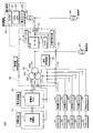
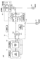
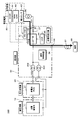
- 1 is a schematic diagram illustrating an example of a circuit configuration of a system interconnection system according to a first embodiment.
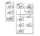
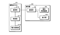
- FIG. 2 is a block diagram illustrating an example of a communication connection mode of an interconnection panel, a storage battery PCS, and a charging / discharging stand according to Embodiment 1, and an internal configuration example of the storage battery PCS and the charging / discharging stand.
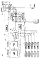
- It is a schematic diagram which shows the 1st example of the grid connection by the grid connection system which concerns on Embodiment 1 when an electric power system is normal.
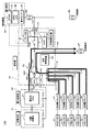
- FIG. 2 is a schematic diagram illustrating an example of an emergency self-sustaining operation by the grid interconnection system according to the first embodiment.
- 4 is a flowchart illustrating an example of a procedure of a process in which the grid interconnection system according to the first embodiment starts an independent operation when a power failure occurs.
- 6 is a flowchart illustrating an example of a procedure of a process performed by the grid interconnection system according to the first embodiment when power is restored.
- 5 is a flowchart illustrating an example of a procedure of a phase synchronization process executed by the storage battery PCS according to the first embodiment.
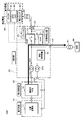
- FIG. 9 is a schematic diagram illustrating an example of a circuit configuration of a system interconnection system according to a second embodiment.
- FIG. 8 is a block diagram illustrating an example of a communication connection mode between an interconnection panel and a storage battery PCS according to a second embodiment, and an example of an internal configuration of the storage battery PCS.
- It is a schematic diagram which shows an example of the grid connection by the grid connection system which concerns on Embodiment 2 when an electric power system is normal.
- It is a schematic diagram which shows an example of the self-sustaining operation at the time of an emergency by the grid interconnection system which concerns on Embodiment 2.
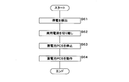
- FIG. 9 is a flowchart illustrating an example of a procedure of a process in which the grid interconnection system according to the second embodiment starts an independent operation when a power failure occurs.
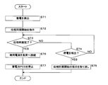
- 13 is a flowchart illustrating an example of a procedure of a process performed by the grid interconnection system according to the second embodiment when power is restored. It is a schematic diagram which shows the example of the system interconnection at the time of power restoration by the system interconnection system which concerns on Embodiment 2.
- FIG. 13 is a schematic diagram illustrating an example of a circuit configuration of a grid interconnection system according to a third embodiment. It is a schematic diagram which shows the 1st example of the grid connection by the grid connection system which concerns on Embodiment 3 when an electric power system is normal.
- FIG. 15 is a flowchart illustrating an example of a procedure of a process in which the grid interconnection system according to the third embodiment starts an independent operation when a power failure occurs.
- 13 is a flowchart illustrating an example of a procedure of a process performed by the grid interconnection system according to the third embodiment when power is restored.
- FIG. 1 is a schematic diagram illustrating an example of an external configuration of a system interconnection system 100 according to the first embodiment.
- the grid interconnection system 100 is installed in a parking lot, and the parking lot has five parking spaces.
- the grid interconnection system 100 includes a charge / discharge stand 41, 42, 43, 44, 45 for an electric vehicle (51, 52, 53, 54, 55) installed in a parking lot, and a grid connection installed in the parking lot.
- the grid interconnection system 100 can be provided as a device for a business continuity plan (BCP).
- BCP business continuity plan
- the grid interconnection unit includes a storage battery panel 10 that houses a storage battery, a power conversion panel 20 that houses a storage battery PCS (Power Conditioning System), and an interconnection board 30 that houses an interconnection control device that interconnects with a power system. Prepare. Note that the number of charge / discharge stands is not limited to five. FIG. 1 does not show the storage battery, the storage battery PCS, and the interconnection control device. Storage battery PCS corresponds to a power converter.
- the electric vehicle is a plug-in hybrid vehicle (PHEV) or an electric vehicle (EV), and is also referred to as PHEV or EV in this specification.
- the charging / discharging stands 41 to 45 can charge and discharge a battery (on-board storage battery) mounted on the electric vehicle.
- the storage battery PCS housed in the power conversion board 20 can convert electric power in both directions from AC to DC and from DC to AC, and can charge and discharge the storage battery housed in the storage battery board 10.
- the interconnection control device housed in the interconnection board 30 performs a system interconnection operation between the power system, the storage battery PCS, and the charging / discharging stations 41 to 45.
- the interconnection control device can perform an independent operation by the storage battery PCS and the charging / discharging stations 41 to 45. Even when all or a part of the electric vehicle is not parked in the parking lot, the grid interconnection unit supplies the power of the storage battery to the load by the storage battery PCS, so that a required load for the load of the power system is obtained. Power can be supplied.
- the load is various electric devices. For example, the load is an electric device provided in a facility where a parking lot is installed.
- FIG. 2 is a schematic diagram illustrating an example of a circuit configuration of the interconnection system 100 according to the first embodiment.
- the storage battery panel 10 houses a stationary storage battery 11, a control device (not shown), a cooling device, a heater, and the like.
- the power conversion board 20 contains a storage battery PCS21 and a cooling device (not shown) for radiating heat of the storage battery PCS21.
- Storage battery PCS21 includes a control device and a cooling device (not shown).
- the interconnection board 30 includes an interconnection control device 36, a remote IO 31, a VCB (Vacuum Circuit Breaker) 32 as an opening / closing unit, a transformer 33, a UVR (Under Voltage Relay; Under Voltage Relay) 34, and an instrument transformer. Device 35 and the like.
- the interconnection board 30 includes terminal blocks 101 and 102, a disconnector 37, and breakers 103, 104, 111 to 115.
- the terminal block 101 is provided on an electric circuit (high-voltage power line) on the high-voltage lead-in side. That is, the power line from the secondary side of the step-down transformer 85 of the power system and the power line from the primary side of the step-down transformer 86 connected to the general load are connected to the terminal block 101.
- the step-down transformer 85 is connected to a commercial power supply and steps down a voltage from the commercial power supply.
- the general load includes, for example, electrical devices that have relatively little effect even if power is cut off during a disaster.
- the terminal block 102 is provided on an electric circuit (high-voltage power supply line) on the high-voltage extraction side. That is, the power line from the primary side of the step-down transformer 87 connected to the important load is connected to the terminal block 102.
- the important load is an important load (important load) for which it is necessary to continuously supply power even when an abnormality such as a disaster occurs.
- important loads include emergency elevators, electrical equipment that requires continuous operation, building lighting or air conditioning equipment, and the like.
- the VCB 32 is a circuit breaker that accommodates electrodes in a high-vacuum container and diffuses a substance constituting an arc discharge generated between the electrodes when the current is interrupted in the high vacuum to extinguish the arc.
- the instrument transformer 35 measures the voltage and frequency of the electric power from the commercial power supply, and inputs the measured values to the UVR 34.
- the UVR 34 can detect an abnormality such as a short circuit accident or a power failure on the power system side. When detecting an abnormality, the UVR 34 outputs a control signal to the VCB 32 to cut off the electric circuit of the VCB 32.
- a power monitoring unit 80 that monitors the power on the primary side of the step-down transformer 85 is provided in a building that performs power demand management using the grid interconnection system.
- the power monitoring unit 80 is not always essential. When the step-down transformer 85 is not installed, the position monitored by the power monitoring unit 80 is set as appropriate.
- the power monitoring unit 80 includes an OVGR (ground fault overvoltage relay; Over Voltage Ground Relay) 81, an RPR (Reverse Power Relay) / UPR (Under Power Relay) 82, and a power sensor 83.
- the OVGR 80 continuously detects a ground fault in the power system.
- the RPR / UPR 82 can detect an abnormality such as a reverse power flow to the power system or a short circuit accident. Also when an abnormality is detected in the OVGR 81 or the RPR / UPR 82, the electric circuit of the VCB 32 is cut off.
- the remote IO 31 is an AD converter that converts the power (analog value) detected by the power sensor 83 into a digital value.
- the remote IO 31 outputs the converted power (digital value) to the interconnection controller 36.
- the transformer 33 (more specifically, the first winding 331) is connected to the other electrode of the VCB 32 via an electric path.
- the transformer 33 includes a first winding 331, a second winding 332 connected to the breaker 103 via an electric path, and a third winding 333 connected to the breakers 111 to 115 via an electric path.
- the transformer 33 can be a three-phase three-winding transformer.
- the voltage and power (apparent power) on the first winding 331 side can be, for example, 6600 V and 50 kVA.
- the voltage and power on the second winding 332 side can be, for example, 300 V and 50 kVA.
- the voltage and power on the third winding 333 side can be, for example, 210 V and 50 kVA. Voltage and power are not limited to these values.
- the storage battery PCS21 is connected to the breaker 103.
- the storage battery PCS21 can convert electric power in both directions from AC to DC and from DC to AC, and can charge and discharge the stationary storage battery 11.
- One of the three phases of the third winding 333 is connected to the circuit breaker 104.
- a voltage of 105 V to 210 V is supplied as a power supply for the control device and the cooling device included in the storage battery PCS21, and as a power supply for the control device, the cooling device, and the heater in the storage battery panel 10.
- the power lines from the charging / discharging stands 41 to 45 are connected to the breakers 111 to 115, respectively.
- the charging / discharging stands 41 to 45 each include a conversion circuit that can convert electric power in both directions from AC to DC and from DC to AC, and can charge and discharge a battery mounted on the electric vehicles 51 to 55. .
- FIG. 3 is a block diagram showing an example of a communication connection mode of the interconnection panel 30, the storage battery PCS21 and the charging / discharging stand 41, and an example of an internal configuration of the storage battery PCS21 and the charging / discharging stand 41 according to the first embodiment.
- the interconnection panel 30 includes a communication unit 38 that communicates with the storage battery PCS21 and the charging / discharging stand 41.
- the communication unit 38 is connected to the interconnection control device 36 via a communication line.
- the communication unit 38 is connected to the storage battery PCS21 and the charging / discharging stand 41 via a communication line.
- the interconnection control device 36 transmits and receives signals between the storage battery PCS21 and the charging / discharging stand 41 via the communication unit 38.
- Storage battery PCS21 includes a control unit 211, a power conversion unit 212, and a communication unit 213.
- the control unit 211 controls the operation of each unit of the storage battery PCS21.
- the power conversion unit 212 performs conversion from AC to DC and from DC to AC.
- the communication unit 213 is connected to the communication unit 38 via a communication line.
- the storage battery PCS21 transmits and receives signals to and from the interconnection control device 36 by the communication unit 213.
- the interconnection board 30 includes a display unit 301.
- the display unit 301 is a display.
- the display unit 301 displays information regarding the operation of the storage battery PCS21 and the charging / discharging stand 41, and information such as the voltage of the commercial power supply.
- the charging / discharging stand 41 includes a control unit 411, a charging / discharging unit 412, a communication unit 413, and a notification unit 414.
- the control unit 411 controls the operation of each unit of the charging / discharging stand 41.
- the charging / discharging unit 412 executes charging / discharging of the battery of the electric vehicle 51.
- the communication unit 413 is connected to the communication unit 38 via a communication line.
- the charge / discharge stand 41 transmits and receives signals to and from the interconnection control device 36 by the communication unit 413.
- Notification unit 414 notifies information on charging and discharging of the battery of electric vehicle 51.
- the notifying unit 414 may be, for example, a display panel or an indicator light, or may notify a terminal device used by a user or an administrator via wireless communication.
- the information on charge / discharge includes, for example, an operation state such as preparation for charge / discharge, preparation completion, charge / discharge, charge / discharge completion, a state of charge (SOC) of the battery, a required time for full charge, and full charge.
- SOC state of charge
- Information such as the remaining time until, the dischargeable amount, and the charge for charging and discharging can be included. As a result, it is possible to timely grasp information on charging and discharging of the electric vehicle.
- the configuration of the charging / discharging stands 42 to 45 is the same as the configuration of the charging / discharging stand 41.
- the charging / discharging stands 42 to 45 are connected to the communication unit 38 via a communication line, similarly to the charging / discharging stand 41.
- the communication units included in the communication units 38, 213 and 413 and the charge / discharge stands 42 to 45 are, for example, gateways.
- FIG. 4 is a schematic diagram illustrating a first example of system interconnection by the system interconnection system 100 according to the first embodiment when the power system is normal.
- the interconnection control device 36 supplies power from a commercial power supply to the charging / discharging stands 41 to 45 when the power system is normal and the charging mode is set, and the electric vehicle is controlled by the charging / discharging stands 41 to 45. 51 to 55 can be charged.
- the system interconnection system 100 can be used as a quick charging station for an electric vehicle.
- power is supplied from the commercial power supply to the important load when the power system is normal.
- power is supplied from the commercial power supply to the general load.
- the power to be supplied in the event of an abnormality such as a disaster is minimized, the power is continuously supplied to the important load, and the power is supplied to the important load. Power can be supplied for a longer time.
- An important load corresponds to a specific load.
- FIG. 5 is a schematic diagram illustrating a second example of system interconnection by the interconnection system 100 according to the first embodiment when the power system is normal.
- a part of the flow of power is indicated by arrows.
- the power receiving point power at a predetermined location is equal to or greater than a threshold value in a state where the power system is normal and the energy management mode (energy management mode) is set, for example, the power detected by the power sensor 83 Is greater than or equal to the threshold
- power is supplied from the charging / discharging stations 41 to 45 to the important load and the general load so that is equal to or less than the threshold.
- the interconnection control device 36 causes the storage battery PCS21 to supply power to the important load and the general load.
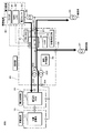
- FIG. 6 is a schematic diagram illustrating an example of an emergency self-sustaining operation by the grid interconnection system 100 according to the first embodiment.
- the flow of electric power is indicated by arrows.
- the interconnection control device 36 cuts off the electric path of the VCB 32 to disconnect the commercial power supply from the important load.
- the independent operation by the interconnection control device 36 can be enabled.
- the interconnection control device 36 can supply power to the important load from at least one of the charging / discharging stations 41 to 45 or the storage battery PCS21 when the power system is abnormal.
- FIG. 7 is a flowchart illustrating an example of a procedure of a process in which the grid interconnection system 100 according to the first embodiment starts an independent operation when a power failure occurs.
- the step is abbreviated as S.
- the UVR 34 detects a power failure of the commercial power supply based on the voltage from the commercial power supply (S11).
- the UVR 34 receives the voltage from the commercial power supply measured by the instrument transformer 35, and detects a power failure of the commercial power supply when the input voltage falls below a predetermined voltage, and cuts off the electric circuit to the VCB 32.
- the interconnection control device 36 stops the storage battery PCS21 (S13). In S13, the interconnection control device 36 outputs a control signal for stopping to the storage battery PCS21, and the storage battery PCS21 stops according to the control signal. Next, the interconnection control device 36 stops the charge / discharge stands 41 to 45 (S14). In S14, the interconnection control device 36 outputs a control signal for stopping to the charging / discharging stands 41 to 45, and the charging / discharging stands 41 to 45 stop according to the control signal. At the time of the power failure of the commercial power supply, the storage battery PCS21 and the charging / discharging stands 41 to 45 may have stopped themselves due to some error.
- the interconnection control device 36 outputs a control signal for stopping the storage battery PCS21 and the charging / discharging. Stop the stands 41 to 45 without fail.
- the interconnection control device 36 operates the storage battery PCS21 (S15).
- the interconnection control device 36 outputs a control signal for starting operation in the independent operation mode to the storage battery PCS21, and the storage battery PCS21 starts operation according to the control signal.
- the storage battery PCS21 thereafter performs an operation of an independent operation.
- the interconnection control device 36 receives the signals indicating the detection of the power failure by the UVR 34, the interruption of the electric circuit by the VCB 32, and the stop of the storage battery PCS21, respectively, and performs the process of S15 after receiving all these signals.
- power for control is supplied from the storage battery PCS21 to the charging / discharging stations 41 to 45.
- the interconnection control device 36 operates the charge / discharge stands 41 to 45 (S16).
- the interconnection control device 36 outputs a control signal for starting operation to the charging / discharging stands 41 to 45, and the charging / discharging stands 41 to 45 start operating according to the control signal.
- the grid interconnection system 100 ends the self-sustained operation start process.
- the grid interconnection system 100 After the grid interconnection system 100 starts the self-sustaining operation, as shown in FIG. 6, power is supplied from the storage battery PCS21 and the charging / discharging stations 41 to 45 to the important loads.
- the storage battery PCS21 When the interconnection control device 36 performs an independent operation, the storage battery PCS21 performs voltage control and operates as a voltage source. The current required to obtain the required power is realized by connecting the charging / discharging stations 41 to 44 to the storage battery PCS21 operating as a voltage source and operating as a current source. Even when a required power cannot be supplied from the charge / discharge stands 41 to 45 to the important load during a power outage, power can be supplied from the storage battery PCS21 to the important load. For this reason, the grid interconnection system 100 can supply required power to the important load of the power system as a whole.
- the interconnection control device 36 determines that the surplus power from the charging / discharging stations 41 to 45 to the storage battery PCS21 Supply power. Thereby, when the electric vehicle is parked in the parking space, the electric power of the electric vehicle can be effectively used.
- the interconnection control device 36 determines that the important loads from both the charging / discharging stations 41 to 45 and the storage battery PCS21.
- Supply power to For example, when the capacity of the important load is 50 kVA and the power of 30 kVA can be supplied from the charging / discharging stations 41 to 45 in total, the power of 20 kVA is supplied from the storage battery PCS 21 and the high voltage side of the transformer 33 is used. 50 kVA of power can be supplied to critical loads.
- the capacity of the important load changes, only power suitable for the capacity of the important load can be supplied. Thereby, when all or a part of the required number of electric vehicles is not parked in the parking space, the insufficient power can be supplied from the storage battery PCS21, and the required power is supplied to the important load of the power system. can do.
- FIG. 8 is a flowchart illustrating an example of a procedure of a process performed by the grid interconnection system 100 according to the first embodiment when power is restored.
- the UVR 34 detects the restoration of the commercial power based on the voltage from the commercial power (S21).
- the UVR 34 is supplied with a voltage from the commercial power supply measured by the instrument transformer 35, and when the input voltage exceeds a predetermined voltage, detects the restoration of the commercial power supply, and sends a signal to the interconnection control device 36. Outputs a control signal corresponding to the detection of power restoration.
- the interconnection control device 36 instructs the storage battery PCS21 to start synchronizing the voltage phase of the power from the storage battery PCS21 with the voltage phase of the power from the commercial power supply in response to the control signal from the UVR 34 (S22). .
- the interconnection control device 36 transmits a control signal instructing the start of phase synchronization to the storage battery PCS21 via the communication unit 38.
- Storage battery PCS21 executes a phase synchronization process for synchronizing the voltage phase of the power from storage battery PCS21 with the voltage phase of the power from the commercial power supply in accordance with a control signal from interconnection control device 36.
- FIG. 9 is a flowchart illustrating an example of a procedure of a phase synchronization process performed by the storage battery PCS21 according to the first embodiment.
- Storage battery PCS21 determines whether there is an instruction to start phase synchronization (S301). For example, when the control unit 213 has received a control signal instructing the start of phase synchronization, the storage battery PCS21 determines that there is an instruction to start phase synchronization. If control unit 213 does not receive a control signal for instructing the start of phase synchronization, or if control unit 213 receives a control signal for canceling the start of phase synchronization, storage battery PCS21 determines that there is no instruction to start phase synchronization. I do.
- the storage battery PCS21 ends the phase synchronization processing. After ending the phase synchronization processing, the storage battery PCS21 continues the self-sustaining operation, and repeats the processing from S301 as needed.
- the storage battery PCS21 waits for the phase synchronization process for a predetermined time and continues the independent operation (S302).
- the standby time is set in advance and is, for example, 300 seconds.
- the storage battery PCS21 acquires the voltage and frequency of the electric power from the commercial power supply (S303).
- S303 for example, the voltage and frequency measured by the instrument transformer 35 are input to the storage battery PCS21.
- Battery PCS21 may measure the voltage and frequency of the electric power from the commercial power supply.
- storage battery PCS21 determines whether or not the voltage and frequency of the electric power from the commercial power supply are within a predetermined range (S304). For example, storage battery PCS21 determines whether the voltage of the electric power from the commercial power supply exceeds a predetermined lower limit voltage and is lower than a predetermined upper limit voltage. Further, storage battery PCS21 determines whether the frequency of the electric power from the commercial power supply exceeds a predetermined lower limit frequency and is lower than a predetermined upper limit frequency.
- the range of the voltage and the frequency is a range of the voltage and the frequency of the power stably supplied from the commercial power supply when the power system is normal, and is set in advance. For example, the lower limit voltage is the same as the voltage that triggers the operation of the UVR 34.
- the storage battery PCS21 displays information indicating the outside of the synchronization range on the display unit 301 (S305). For example, storage battery PCS21 transmits information indicating the out-of-synchronization range from communication unit 213 to display unit 301, and display unit 301 receives information from storage battery PCS21 via communication unit 38, and “out of synchronization range”. Is displayed.
- storage battery PCS21 determines whether or not there is an instruction to start phase synchronization (S306). If there is no instruction to start phase synchronization (S306: NO), the storage battery PCS21 ends the phase synchronization processing. After ending the phase synchronization processing, the storage battery PCS21 continues the self-sustaining operation, and repeats the processing from S301 as needed.
- storage battery PCS21 If there is an instruction to start phase synchronization (S306: YES), storage battery PCS21 returns the process to S303. By repeating the processes of S303 to S306, storage battery PCS21 waits for phase synchronization until the voltage or frequency of the electric power from the commercial power supply falls within a predetermined range, and continues the self-sustaining operation. In the state where the self-sustaining operation is performed, the storage battery PCS21 continues to supply power to the important load. At this time, storage battery PCS21 maintains the frequency of the electric power from storage battery PCS21 in a self-sustaining operation state. When the power is restored but the power system is unstable, the voltage or frequency of the electric power from the commercial power supply deviates from a predetermined range.
- the voltage and frequency of the electric power from the commercial power supply can be stabilized within a predetermined range. Since the storage battery PCS21 waits for phase synchronization and continues the self-sustaining operation, the unstable commercial power supply is prevented from being connected to the important load, and stable power supply to the important load is continued.
- storage battery PCS21 has a value of the difference between the zero-cross point of the voltage from commercial power supply and the zero-cross point of the voltage from storage battery PCS21. Is smaller than or equal to the threshold (S307).
- the zero-cross point is the moment when the value of the AC voltage becomes zero, and the moment when the polarity of the AC voltage is reversed.
- the storage battery PCS21 measures, for example, the time of the zero-cross point, and calculates the difference between the measured times.
- the threshold is set in advance.
- the storage battery PCS21 determines whether the frequency of the electric power from the commercial power supply is lower than the basic frequency (S308).
- the fundamental frequency is predetermined. For example, the fundamental frequency is 50 Hz or 60 Hz.
- the storage battery PCS21 increases the frequency of the power from the storage battery PCS21 by a predetermined amount than the frequency of the power from the commercial power supply (S309).
- the predetermined amount for increasing the frequency is predetermined to a value sufficiently smaller than the fundamental frequency.
- the predetermined amount is, for example, 0.02 Hz.
- storage battery PCS21 slightly increases the frequency of the power from storage battery PCS21 in response to the relatively low frequency of the power from the commercial power supply so that the frequency does not fall outside the predetermined range.
- the storage battery PCS21 reduces the frequency of the electric power from the storage battery PCS21 by a predetermined amount from the frequency of the electric power from the commercial power supply (S310).
- the predetermined amount for decreasing the frequency is predetermined to a value sufficiently smaller than the fundamental frequency, and is, for example, 0.02 Hz.
- storage battery PCS21 slightly reduces the frequency of the power from storage battery PCS21 in accordance with the relatively high frequency of the power from the commercial power supply so that the frequency does not deviate from the predetermined range.
- the storage battery PCS21 adjusts the frequency of the power from the storage battery PCS21 to the frequency of the power from the commercial power supply (S311).
- storage battery PCS21 adjusts the zero-cross point of the voltage from storage battery PCS21 to the zero-cross point of the voltage from the commercial power supply (S312).
- the control unit 211 stores in advance a table that defines a time change of a voltage that forms a sine wave.
- storage battery PCS21 reads the data corresponding to the zero-cross point in the table at the time of the zero-cross point of the voltage from the commercial power supply, and locks the zero-cross point of the voltage from storage battery PCS21 to the zero-cross point of the voltage from the commercial power supply. I do.
- phase jump occurs.
- the occurrence of phase jump is suppressed by adjusting the zero-cross points in a state where the difference between the zero-cross points is small, and the voltage phase of the power from the storage battery PCS21 and the voltage phase of the power from the commercial power supply are reduced. Can be synchronized. Further, even when the frequency of the electric power from the commercial power supply is significantly different from the frequency of the electric power from the storage battery PCS21, a phase jump occurs.
- the occurrence of phase jump is suppressed by adjusting the zero-cross point after adjusting the frequency of the electric power, and then the voltage phase of the electric power from the storage battery PCS21 and the voltage phase of the electric power from the commercial power supply are adjusted. Can be synchronized.
- the storage battery PCS21 notifies the interconnection control device 36 that the phase synchronization has been completed (S313). For example, storage battery PCS21 transmits a signal indicating completion of phase synchronization to interconnection control device 36 from communication unit 213. Next, the storage battery PCS21 sets the input gain of the voltage controller that controls the voltage input to the power conversion unit 212 to zero (S314).
- the storage battery PCS21 performs voltage control by the voltage controller. In a state where power is supplied from the commercial power supply, the voltage is fixed by the commercial power supply. In S314, the storage battery PCS21 stops controlling the voltage by setting the input gain of the voltage controller to zero. This prevents the battery PCS21 from trying to control the fixed voltage and the voltage control by the storage battery PCS21 from running away. Since the process of S314 is performed after the phase synchronization is completed, the voltage from the storage battery PCS21 and the voltage from the commercial power supply do not greatly differ due to the stop of the voltage control. The storage battery PCS21 ends the phase synchronization processing as described above.
- the interconnection control device 36 determines whether or not the phase synchronization has been completed (S23). For example, when a signal indicating completion of phase synchronization is received through the communication unit 38, the interconnection control device 36 determines that phase synchronization has been completed. If there is no signal indicating that phase synchronization has been completed, the interconnection control device 36 determines that phase synchronization has not been completed. If the phase synchronization has not been completed (S23: NO), the interconnection control device 36 determines whether the UVR 34 has detected a power failure of the commercial power supply (S24).
- the interconnection control device 36 determines that the UVR 34 has detected a power failure of the commercial power supply. If no power failure is detected (S24: NO), the interconnection control device 36 returns the process to S23.
- the interconnection control device 36 cancels the instruction to start the phase synchronization to the storage battery PCS21 (S25).
- the interconnection control device 36 stops transmitting the control signal instructing the start of the phase synchronization, or transmits a control signal for canceling the start of the phase synchronization to the storage battery PCS21 through the communication unit 38.
- storage battery PCS21 stops the phase synchronization processing.
- the interconnection control device 36 ends the processing without restarting the power supply from the commercial power supply.
- the interconnection control device 36 causes the storage battery PCS21 to stop the phase synchronization processing. In this case, the power supply from the commercial power supply is not restarted, and the grid interconnection system 100 continues the independent operation.
- the interconnection control device 36 stops the charge / discharge stands 41 to 45 (S26).
- the interconnection control device 36 outputs a control signal for stopping to the charge / discharge stands 41 to 45 through the communication unit 38.
- the charging / discharging stands 41 to 45 stop according to the control signal.
- the interconnection control device 36 turns on the VCB 32 and connects the commercial power supply to the important load (S27).
- the interconnection control device 36 outputs a control signal for connecting the electric circuit to the VCB 32.
- the VCB 32 connects an electric circuit according to a control signal.
- the interconnection control device 36 stops the storage battery PCS21 (S28).
- S25 the interconnection control device 36 outputs a control signal for stopping to the storage battery PCS21 through the communication unit 38. Storage battery PCS21 stops in response to the control signal.
- the system interconnection system 100 ends the process at the time of power restoration.
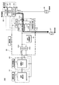
- FIG. 10 is a schematic diagram illustrating an example of system interconnection at the time of power restoration by the interconnection system 100 according to the first embodiment.
- the grid-connected system 100 connects the commercial power supply to the important load, and supplies power from the commercial power supply to the important load.
- the grid interconnection system 100 connects the commercial power supply to the important load while power is being supplied from the storage battery PCS21 to the important load, and then stops the storage battery PCS21. Therefore, the supply of power to the important load is not interrupted. That is, the state is switched from a state in which power is supplied from the storage battery PCS21 to the important load to a state in which power is supplied from the commercial power supply to the important load without a momentary interruption. In this way, the power supply from the commercial power supply to the important load is restarted.
- the commercial power supply is connected to the important load.
- a commercial power supply is connected to the important load while power is being supplied from the storage battery PCS21 to the important load, the power from the storage battery PCS21 and the power from the commercial power supply are simultaneously supplied to the important load.
- phase synchronization a commercial power supply can be connected without giving stress such as voltage fluctuation to an important load.
- the interconnection control device 36 can restart the charge / discharge stands 41 to 45 and the storage battery PCS21 in order to perform interconnection of the system.
- the storage battery PCS21 thereafter performs a system interconnection operation.
- the grid interconnection system 100 can execute the grid interconnection as described with reference to FIG. 4 or FIG.
- the charging / discharging stands 41 to 45 are stopped before the power supply from the commercial power supply to the important load is started.
- the process at the time of power recovery may be performed without performing the process of stopping. In this case, the power supply source to the important load is switched without stopping the charge / discharge stands 41 to 45.
- the system interconnection system 100 may be configured to be interconnected at a low voltage.
- the voltage and the power (apparent power) on the first winding 331 side of the transformer 33 can be set to, for example, 210 V and 49 kVA.
- the voltage and power (apparent power) on the 332 side can be, for example, 300 V and 49 kVA
- the voltage and power (apparent power) on the third winding 333 side can be, for example, 210 V and 49 kVA.
- the transformer is not limited to the three-winding transformer, and may be configured to include two two-winding transformers.
- the grid interconnection system 100 may include a power supply unit such as a solar cell, instead of the charging / discharging stations 41 to 45 or in addition to the charging / discharging stations 41 to 45. Also in this embodiment, the grid interconnection system 100 can supply power to the important load from the storage battery PCS21 at the time of a power failure, and can supply power to the important load without interrupting the power supply at the time of power restoration. Can be switched to commercial power.
- a power supply unit such as a solar cell
- FIG. 11 is a schematic diagram illustrating an example of a circuit configuration of the interconnection system 100 according to the second embodiment.
- the grid interconnection system 100 does not include the charging / discharging stands 41 to 45 as compared with the first embodiment.
- the interconnection board 30 does not include the breakers 111 to 115 as compared with the first embodiment.
- the interconnection board 30 does not include the transformer 33 that is a three-winding transformer, but includes a transformer 302 and a transformer 303 that are two-winding transformers.
- the high voltage side of the transformer 302 is connected to the VCB 32 via an electric line.
- the low voltage side of the transformer 302 is connected to the breaker 103 via an electric line.
- Transformer 303 is connected between the high voltage side of transformer 302 and breaker 104.
- the power supplied to storage battery PCS21 and the power supplied from storage battery PCS21 are transformed by transformer 302.
- the power transformed by the transformer 303 is supplied as a power supply for the control device and the cooling device included in the storage battery PCS21, and further as a power supply for the control device, the cooling device, and the heater in the storage battery panel 10.
- the configuration of the other parts of the interconnection board 30 is the same as that of the first embodiment.
- the configurations of the storage battery panel 10, the power conversion panel 20, the power monitoring unit 80, and the step-down transformers 85, 86, and 87 are the same as those in the first embodiment.
- the load is an electric device provided in the building.
- the general load is, for example, an electrical device that has relatively little effect even if power is cut off during a disaster.
- the important load is an electrical device that needs to continuously supply power even in the event of an abnormality such as a disaster.
- critical loads are emergency elevators or electrical equipment that requires continuous operation.
- FIG. 12 is a block diagram illustrating an example of a communication connection mode between the interconnection panel 30 and the storage battery PCS21 according to the second embodiment, and an example of an internal configuration of the storage battery PCS21.
- the interconnection board 30 includes a communication unit 38.
- the communication unit 38 is connected to the interconnection control device 36 via a communication line, and is also connected to the storage battery PCS21 via a communication line.
- the configuration of the storage battery PCS21 is the same as that of the first embodiment.
- FIG. 13 is a schematic diagram illustrating an example of grid interconnection by the grid interconnection system 100 according to the second embodiment when the power system is normal.
- the interconnection control device 36 can supply power from the commercial power supply to the storage battery PCS21 and charge the storage battery PCS21 with the stationary storage battery 11. If the power receiving point power at the predetermined location is equal to or higher than the threshold, the interconnection control device 36 causes the storage battery PCS21 to supply power to the important load and the general load so that the power becomes equal to or lower than the threshold.
- the system interconnection system 100 can perform system interconnection so that electric power is supplied from a commercial power supply to a general load and an important load.
- FIG. 14 is a schematic diagram illustrating an example of an emergency self-sustaining operation by the grid interconnection system 100 according to the second embodiment.
- the flow of electric power is indicated by arrows.
- the interconnection control device 36 cuts off the electric path of the VCB 32 to disconnect the commercial power supply from the important load. Thereby, the independent operation by the interconnection control device 36 can be enabled.
- the interconnection control device 36 supplies power from the storage battery PCS21 to the important load when the power system is abnormal.
- FIG. 15 is a flowchart illustrating an example of a procedure of a process in which the grid interconnection system 100 according to the second embodiment starts an independent operation when a power failure occurs.
- the UVR 34 detects a power failure of the commercial power supply based on the voltage from the commercial power supply (S41).
- the UVR 34 outputs a control signal for cutting off the electric circuit to the VCB 32, and the VCB 32 cuts off the electric circuit, so that the grid interconnection system 100 disconnects the commercial power supply and the general load from the important load (S42).
- the interconnection control device 36 stops the storage battery PCS21 (S43). In S43, the interconnection control device 36 outputs a control signal for stopping to the storage battery PCS21, and the storage battery PCS21 stops according to the control signal. Next, the interconnection control device 36 operates the storage battery PCS21 (S44). In S44, the interconnection control device 36 outputs a control signal for starting operation in the independent operation mode to the storage battery PCS21, and the storage battery PCS21 starts operation according to the control signal. The storage battery PCS21 thereafter performs an operation of an independent operation.
- the interconnection control device 36 receives the signals indicating the detection of the power failure by the UVR 34, the interruption of the electric circuit by the VCB 32, and the stop of the storage battery PCS21, respectively, and performs the process of S44 after receiving all of these signals.
- the grid interconnection system 100 ends the self-sustained operation start process.
- FIG. 16 is a flowchart illustrating an example of a procedure of a process performed by the grid interconnection system 100 according to the second embodiment when power is restored.
- the UVR 34 detects the restoration of the commercial power based on the voltage from the commercial power (S51).
- the UVR 34 outputs a control signal corresponding to the detection of the restoration of power to the interconnection control device 36.
- the interconnection control device 36 supplies the storage battery PCS21 with the voltage phase of the electric power from the storage battery PCS21 and the voltage of the electric power from the commercial power supply.
- An instruction to start synchronization with the phase is issued (S52).
- Storage battery PCS21 executes a phase synchronization process for synchronizing the voltage phase of the power from storage battery PCS21 with the voltage phase of the power from the commercial power supply.
- the contents of the phase synchronization processing are the same as in the first embodiment.
- the storage battery PCS21 notifies the interconnection control device 36 that the phase synchronization has been completed.
- the interconnection control device 36 determines whether or not the phase synchronization has been completed (S53). For example, when a signal indicating completion of phase synchronization is received through the communication unit 38, the interconnection control device 36 determines that phase synchronization has been completed. If the phase synchronization has not been completed, the interconnection control device 36 determines whether or not the UVR 34 has detected a power failure of the commercial power supply (S54). If no power failure is detected (S54: NO), the interconnection control device 36 returns the process to S53.
- the interconnection control device 36 cancels the instruction to start the phase synchronization to the storage battery PCS21 (S55). In response to the process in S55, storage battery PCS21 stops the phase synchronization process. After the processing in S55, the interconnection control device 36 ends the processing without restarting the power supply from the commercial power supply. As described above, when the power supply is stopped again while the storage battery PCS21 is executing the phase synchronization processing, the power supply from the commercial power supply is not restarted, and the grid interconnection system 100 continues the independent operation.
- the interconnection control device 36 turns on the VCB 32 and connects the commercial power supply to the important load (S56).
- the interconnection control device 36 outputs a control signal for connecting the electric circuit to the VCB 32, and the VCB 32 connects the electric circuit.
- the commercial power supply is connected to the important load.
- the interconnection control device 36 stops the storage battery PCS21 (S57). The system interconnection system 100 ends the process at the time of power restoration.
- FIG. 17 is a schematic diagram illustrating an example of system interconnection at the time of power restoration by the interconnection system 100 according to the second embodiment.
- the grid-connected system 100 connects the commercial power supply to the important load, and supplies power from the commercial power supply to the important load.
- the grid interconnection system 100 switches from a state in which power is supplied from the storage battery PCS21 to the important load to a state in which power is supplied from the commercial power supply to the important load without a momentary interruption. In this way, the power supply from the commercial power supply to the important load is restarted.
- the interconnection control device 36 can restart the storage battery PCS21 in order to perform system interconnection.
- the storage battery PCS21 thereafter performs a system interconnection operation.
- the system interconnection system 100 can execute the system interconnection as described with reference to FIG.
- the grid interconnection system 100 supplies power to the important load from the storage battery PCS21 at the time of a power outage, and does not interrupt power supply to the important load at the time of power restoration. Can be switched to commercial power.
- a three-winding transformer may be provided instead of the transformer 302 and the transformer 303, which are two-winding transformers.
- the system interconnection system 100 may include a plurality of storage battery panels 10 and a power conversion panel 20 and supply power from the plurality of storage batteries PCS21.
- the grid interconnection system 100 forms a part of a FEMS (Factory Energy Management System).
- the grid interconnection system 100 is installed in a factory.
- FIG. 18 is a schematic diagram illustrating an example of a circuit configuration of the interconnection system 100 according to the third embodiment.
- the configurations of the interconnection panel 30, the storage battery panel 10, the power conversion panel 20, the power monitoring unit 80, and the step-down transformers 85 and 87 are the same as those in the second embodiment.
- the grid interconnection system 100 does not include the step-down transformer 86 as compared with the second embodiment.
- the step-down transformer 87 is connected to a load 88.
- the load 88 is an electric device provided in a factory. For example, the load 88 is factory equipment or lighting.
- the communication connection between the interconnection panel 30 and the storage battery PCS21 and the internal configuration of the storage battery PCS21 are the same as those in the second embodiment.
- storage battery PCS21 transmits a signal indicating that it is operating from communication unit 213.
- the interconnection control device 36 receives, via the communication unit 38, a signal indicating that the storage battery PCS21 is operating.
- FIG. 19 is a schematic diagram illustrating a first example of system interconnection by the system interconnection system 100 according to the third embodiment when the power system is normal.
- a part of the flow of power is indicated by arrows.
- the interconnection control device 36 performs system interconnection so that electric power is supplied to the load 88 from the commercial power supply.
- FIG. 20 is a schematic diagram illustrating a second example of system interconnection by the interconnection system 100 according to the third embodiment when the power system is normal.
- the interconnection control device 36 causes the storage battery PCS21 to supply power to the load 88. Further, the interconnection control device 36 can supply electric power from a commercial power supply to the storage battery PCS21 to charge the storage battery PCS21 with the stationary storage battery 11.
- FIG. 21 is a schematic diagram illustrating an example of an emergency self-sustaining operation by the grid interconnection system 100 according to the third embodiment.
- the flow of electric power is indicated by arrows.
- the interconnection control device 36 cuts off the electric path of the VCB 32 to disconnect the commercial power supply from the important load. Thereby, the independent operation by the interconnection control device 36 can be enabled.
- the interconnection control device 36 supplies power from the storage battery PCS21 to the important load when the power system is abnormal.
- FIG. 22 is a flowchart illustrating an example of a procedure of a process in which the grid interconnection system 100 according to the third embodiment starts an independent operation when a power failure occurs.
- the UVR 34 detects a power failure of the commercial power supply based on the voltage from the commercial power supply (S61).
- the UVR 34 outputs a control signal for interrupting the electric circuit to the VCB 32, and the VCB 32 interrupts the electric circuit, whereby the grid interconnection system 100 disconnects the commercial power from the load 88 (S62).
- the interconnection control device 36 stops the storage battery PCS21 (S63). In S63, the interconnection control device 36 outputs a control signal for stopping to the storage battery PCS21, and the storage battery PCS21 stops according to the control signal. Next, the interconnection control device 36 operates the storage battery PCS21 (S64). In S64, the interconnection control device 36 outputs a control signal for starting operation in the independent operation mode to the storage battery PCS21, and the storage battery PCS21 starts operation according to the control signal. The storage battery PCS21 thereafter performs an operation of an independent operation.
- the interconnection control device 36 receives signals indicating the detection of a power failure by the UVR 34, the interruption of the electric circuit by the VCB 32, and the stop of the storage battery PCS21, and performs the process of S64 after receiving all of these signals.
- the grid interconnection system 100 ends the self-sustained operation start process.
- the grid interconnection system 100 After the grid interconnection system 100 starts the self-sustaining operation, power is supplied from the storage battery PCS21 to the load 88 as shown in FIG.
- the interconnection control device 36 When the interconnection control device 36 performs an independent operation, the storage battery PCS21 performs voltage control and operates as a voltage source. In this way, the grid interconnection system 100 can supply required power to the load 88 by supplying power from the storage battery PCS21 at the time of a power failure. Therefore, even during a power outage, power is supplied to the load 88 in the factory, thereby preventing the factory from stopping operation.
- FIG. 23 is a flowchart illustrating an example of a procedure of a process performed by the grid interconnection system 100 according to the third embodiment at the time of power restoration.
- the UVR 34 detects the restoration of the commercial power based on the voltage from the commercial power (S71).
- the interconnection control device 36 instructs the storage battery PCS21 to start synchronizing the voltage phase of the power from the storage battery PCS21 with the voltage phase of the power from the commercial power supply (S72).
- Storage battery PCS21 executes a phase synchronization process for synchronizing the voltage phase of the power from storage battery PCS21 with the voltage phase of the power from the commercial power supply.
- the content of the phase synchronization processing is the same as in the first and second embodiments.
- the storage battery PCS21 notifies the interconnection control device 36 that the phase synchronization has been completed.
- the interconnection control device 36 determines whether or not the phase synchronization has been completed (S73). If the phase synchronization has not been completed, the interconnection controller 36 determines whether the UVR 34 has detected a power failure of the commercial power supply (S74). If no power failure is detected (S74: NO), the interconnection control device 36 returns the process to S73. When the power failure is detected (S74: YES), the interconnection control device 36 cancels the instruction to start the phase synchronization to the storage battery PCS21 (S75). In response to the process in S75, storage battery PCS21 stops the phase synchronization process. After the processing in S75, the interconnection control device 36 ends the processing without restarting the power supply from the commercial power supply. As described above, when the power is interrupted again during the phase synchronization processing, the power supply from the commercial power supply is not restarted, and the grid interconnection system 100 continues the independent operation.
- the interconnection control device 36 turns on the VCB 32 and connects the commercial power supply to the load 88 (S76). In S76, the commercial power supply is connected to the load 88 by the VCB 32 connecting the electric circuit. Next, the interconnection control device 36 stops the storage battery PCS21 (S77). The system interconnection system 100 ends the process at the time of power restoration.
- the commercial power supply is connected to the load 88, and power is supplied from the commercial power supply to the load 88.
- the grid interconnection system 100 switches from a state in which power is being supplied from the storage battery PCS21 to the load 88 to a state in which power is being supplied from the commercial power supply to the load 88 without any interruption. In this way, the power supply from the commercial power supply to the load 88 is restarted.
- the interconnection control device 36 can restart the storage battery PCS21 in order to perform system interconnection.
- the storage battery PCS21 thereafter performs a system interconnection operation.
- the system interconnection system 100 can execute the system interconnection as described with reference to FIG.
- the grid interconnection system 100 supplies power from the storage battery PCS21 to the load 88 at the time of a power outage, and power supply to the load 88 without interruption of the power supply at the time of power restoration. Can be switched to commercial power. Therefore, when the power is restored, the power supply to the load 88 in the factory is not interrupted, and the interruption of the operation of the factory is prevented.
- a three-winding transformer may be provided instead of the transformer 302 and the transformer 303, which are two-winding transformers.
- the system interconnection system 100 may include a plurality of storage battery panels 10 and a power conversion panel 20 and supply power from the plurality of storage batteries PCS21.
Landscapes
- Engineering & Computer Science (AREA)
- Power Engineering (AREA)
- Transportation (AREA)
- Mechanical Engineering (AREA)
- Business, Economics & Management (AREA)
- Emergency Management (AREA)
- Life Sciences & Earth Sciences (AREA)
- Sustainable Development (AREA)
- Sustainable Energy (AREA)
- Supply And Distribution Of Alternating Current (AREA)
- Stand-By Power Supply Arrangements (AREA)
- Charge And Discharge Circuits For Batteries Or The Like (AREA)
- Electric Propulsion And Braking For Vehicles (AREA)
- Inverter Devices (AREA)
Abstract
Description
(実施形態1)
図1は、実施形態1に係る系統連系システム100の外観構成の一例を示す模式図である。図1の例では、系統連系システム100は駐車場に設置されており、駐車場は5台分の駐車スペースを有する。系統連系システム100は、駐車場に設置される電動自動車(51、52、53、54、55)用の充放電スタンド41、42、43、44、45と、駐車場に設置される系統連系ユニットとを備える。系統連系システム100は、事業継続計画(BCP)のための機器として提供することができる。系統連系ユニットは、蓄電池を収容する蓄電池盤10、蓄電池PCS(Power Conditioning System)を収容する電力変換盤20、電力系統との系統連系を行う連系制御装置を収容する連系盤30を備える。なお、充放電スタンドの数は5個に限定されない。図1中には、蓄電池、蓄電池PCS及び連系制御装置は図示していない。蓄電池PCSは、電力変換装置に対応する。
実施形態2においては、充放電スタンド41~45を備えていない系統連系システム100を示す。実施形態1には、駐車場に設置された系統連系システム100の例を示したが、実施形態2に係る系統連系システム100は、例えば、建物内に設置されている。
実施形態3においては、産業用の系統連系システム100の例を示す。実施形態3に係る系統連系システム100は、FEMS(工場エネルギー管理システム;Factory Energy Management System)の一部を構成する。系統連系システム100は、工場内に設置されている。
11 定置蓄電池
20 電力変換盤
21 蓄電池PCS(電力変換装置)
30 連系盤
32 VCB
33 変圧器
34 UVR
36 連系制御装置
41、42、43、44、45 充放電スタンド
51、52、53、54、55 電動自動車
100 系統連系システム
Claims (8)
- 電力系統との系統連系システムであって、
蓄電池と、
該蓄電池からの電力を交流へ変換する電力変換装置と、
商用電源から負荷へ電力を供給し、前記商用電源が停電した場合に前記電力変換装置から前記負荷へ電力を供給する連系制御装置とを備え、
前記連系制御装置は、
前記商用電源が復電した場合に、前記商用電源から前記負荷への電力供給を開始し、前記商用電源から前記負荷への電力供給の開始後に、前記電力変換装置から前記負荷への電力供給を停止する
ことを特徴とする系統連系システム。 - 前記電力変換装置は、前記商用電源が復電した場合に、前記電力変換装置から前記負荷へ供給している電力の電圧位相を、前記商用電源からの電力の電圧位相に同期させ、
前記連系制御装置は、前記電力変換装置から前記負荷へ供給している電力の電圧位相が前記商用電源からの電力の電圧位相に同期した後に、前記商用電源から前記負荷への電力供給を開始する
ことを特徴とする請求項1に記載の系統連系システム。 - 前記電力変換装置は、前記電力変換装置から前記負荷へ供給している電力の電圧位相を前記商用電源からの電力の電圧位相に同期させるために、
前記電力変換装置から前記負荷へ供給している電力の周波数を、前記商用電源からの電力の周波数に合わせ、
電力の周波数が合った後に、前記電力変換装置から前記負荷へ供給している電力のゼロクロス点を、前記商用電源からの電力のゼロクロス点に合わせる
ことを特徴とする請求項2に記載の系統連系システム。 - 前記電力変換装置は、
前記商用電源からの電力の電圧及び周波数が所定の範囲内であるか否かを判定し、
前記電圧及び前記周波数が所定の範囲内である場合に、前記電力変換装置から前記負荷へ供給している電力の電圧位相を、前記商用電源からの電力の電圧位相に同期させ、
前記電圧又は前記周波数が所定の範囲内ではない場合に、位相同期のための処理を待機し、前記負荷への電力供給を続行する
ことを特徴とする請求項2又は3に記載の系統連系システム。 - 電動自動車用の充放電スタンドを更に備え、
前記連系制御装置は、
前記商用電源が停電した場合に、前記電力変換装置及び前記充放電スタンドから前記負荷へ電力を供給する
ことを特徴とする請求項1乃至4のいずれか一つに記載の系統連系システム。 - 前記連系制御装置は、
前記商用電源が停電した場合に、前記電力変換装置から特定の負荷へ電力を供給し、
前記商用電源が復電した場合に、前記商用電源から前記特定の負荷への電力供給を開始する
ことを特徴とする請求項1乃至5のいずれか一つに記載の系統連系システム。 - 商用電源が停電した場合に蓄電池からの電力を負荷へ供給するように制御を行う連系制御装置であって、
前記商用電源が復電した場合に、前記商用電源から前記負荷への電力供給を開始し、前記商用電源から前記負荷への電力供給の開始後に、前記蓄電池からの電力の供給を停止する制御を行うこと
を特徴とする連系制御装置。 - 電力系統との系統連系方法であって、
蓄電池と、
該蓄電池からの電力を交流へ変換する電力変換装置とを用い、
商用電源から負荷へ電力を供給し、
前記商用電源が停電した場合に、前記電力変換装置から前記負荷へ電力を供給し、
前記商用電源が復電した場合に、前記電力変換装置に、前記電力変換装置から前記負荷へ供給している電力の電圧位相を、前記商用電源からの電力の電圧位相に同期させ、
前記電力変換装置から前記負荷へ供給している電力の電圧位相が前記商用電源からの電力の電圧位相に同期した後に、前記商用電源から前記負荷への電力供給を開始し、
前記商用電源から前記負荷への電力供給を開始した後に、前記電力変換装置から前記負荷への電力供給を停止する
ことを特徴とする系統連系方法。
Priority Applications (3)
| Application Number | Priority Date | Filing Date | Title |
|---|---|---|---|
| AU2019316332A AU2019316332B2 (en) | 2018-08-02 | 2019-06-27 | Grid interconnection system, interconnection control device, and grid interconnection method |
| US17/257,694 US11916389B2 (en) | 2018-08-02 | 2019-06-27 | Grid interconnection system, interconnection control device and grid interconnection method |
| DE112019003891.5T DE112019003891B4 (de) | 2018-08-02 | 2019-06-27 | Netzverbindungssystem, Verbindungssteuerungsvorrichtung und Netzverbindungsverfahren |
Applications Claiming Priority (2)
| Application Number | Priority Date | Filing Date | Title |
|---|---|---|---|
| JP2018-146044 | 2018-08-02 | ||
| JP2018146044A JP7026022B2 (ja) | 2018-08-02 | 2018-08-02 | 系統連系システム、連系制御装置及び系統連系方法 |
Publications (1)
| Publication Number | Publication Date |
|---|---|
| WO2020026656A1 true WO2020026656A1 (ja) | 2020-02-06 |
Family
ID=69232157
Family Applications (1)
| Application Number | Title | Priority Date | Filing Date |
|---|---|---|---|
| PCT/JP2019/025511 Ceased WO2020026656A1 (ja) | 2018-08-02 | 2019-06-27 | 系統連系システム、連系制御装置及び系統連系方法 |
Country Status (5)
| Country | Link |
|---|---|
| US (1) | US11916389B2 (ja) |
| JP (1) | JP7026022B2 (ja) |
| AU (1) | AU2019316332B2 (ja) |
| DE (1) | DE112019003891B4 (ja) |
| WO (1) | WO2020026656A1 (ja) |
Cited By (1)
| Publication number | Priority date | Publication date | Assignee | Title |
|---|---|---|---|---|
| WO2023188360A1 (ja) * | 2022-03-31 | 2023-10-05 | 日本電信電話株式会社 | 監視装置、監視方法及びプログラム |
Families Citing this family (23)
| Publication number | Priority date | Publication date | Assignee | Title |
|---|---|---|---|---|
| US11522365B1 (en) * | 2011-05-26 | 2022-12-06 | J. Carl Cooper | Inverter power source load dependent frequency control and load shedding |
| US11183843B1 (en) * | 2011-05-26 | 2021-11-23 | J. Carl Cooper | Power source load control |
| US12071036B2 (en) | 2019-09-06 | 2024-08-27 | Netzero V2G Technologies Llc | Minimum cost demand charge management by electric vehicles |
| FR3101822B1 (fr) | 2019-10-11 | 2021-10-22 | Nw Joules | Dispositif de recharge rapide d’un vehicule automobile |
| CN111469703A (zh) * | 2020-04-22 | 2020-07-31 | 云南电网有限责任公司电力科学研究院 | 一种电动汽车充电系统 |
| US11524601B2 (en) * | 2020-09-11 | 2022-12-13 | Ford Global Technologies, Llc | Vehicle recharge of home energy storage |
| JP7505406B2 (ja) * | 2020-12-28 | 2024-06-25 | トヨタ自動車株式会社 | 充電制御装置 |
| US20220379769A1 (en) * | 2021-05-26 | 2022-12-01 | Netzero V2G Technologies Llc | Bidirectional AC V2G for Multifamily/Workplace Electric Vehicle Charging |
| US12508931B2 (en) | 2021-05-28 | 2025-12-30 | Netzero V2G Technologies Llc | Solar-energized electric vehicle charging |
| US12494667B2 (en) * | 2021-06-29 | 2025-12-09 | Signify Holding B.V. | Step-down voltage module for emergency power systems |
| CN113746131B (zh) * | 2021-08-06 | 2023-11-03 | 万帮数字能源股份有限公司 | 逆变器并联系统及其零馈网控制方法 |
| US12021404B2 (en) * | 2021-09-23 | 2024-06-25 | Der-X Energy Llc | Mobile generator charging system and method |
| US11855470B2 (en) * | 2021-09-23 | 2023-12-26 | Fluidity Power LLC | Mobile generator charging system and method |
| JP7775070B2 (ja) * | 2021-12-24 | 2025-11-25 | 株式会社ダイヘン | 電力システム |
| JP7227411B1 (ja) | 2022-03-10 | 2023-02-21 | 株式会社オリジン | 自動車連携バックアップ装置 |
| JP2023146771A (ja) * | 2022-03-29 | 2023-10-12 | 旭化成ホームズ株式会社 | 充放電制御システム、充放電制御方法およびコンピュータプログラム |
| DE102022210848A1 (de) * | 2022-10-14 | 2024-04-25 | Thomas Emde | System zur Erzeugung regenerativer elektrischer Energie und Versorgung einer Mehrzahl von Verbrauchern |
| US12202371B2 (en) * | 2022-12-22 | 2025-01-21 | Speed Charge, Llc | Dynamic output control of vehicle chargers with respective internal batteries |
| JP2024103288A (ja) * | 2023-01-20 | 2024-08-01 | トヨタ自動車株式会社 | 電力供給制御装置 |
| WO2024189908A1 (en) * | 2023-03-16 | 2024-09-19 | Mitsubishi Electric Corporation | Reconnection control apparatus and power system |
| US12233742B2 (en) * | 2023-07-13 | 2025-02-25 | Ford Global Technologies, Llc | Electric vehicle supply equipment |
| WO2025073851A2 (en) * | 2023-10-04 | 2025-04-10 | Hager-Electro Sas | Bi-directional vehicle charging apparatus and method |
| US20250236197A1 (en) * | 2024-01-23 | 2025-07-24 | Toyota Motor Engineering & Manufacturing North America, Inc. | Health-based energy distribution using vehicle batteries at a location |
Citations (5)
| Publication number | Priority date | Publication date | Assignee | Title |
|---|---|---|---|---|
| JPH10174450A (ja) * | 1996-12-16 | 1998-06-26 | Toshiba Corp | 電力変換装置 |
| JPH10341533A (ja) * | 1997-06-06 | 1998-12-22 | Toshiba Corp | 無停電電源装置 |
| JP2009254192A (ja) * | 2008-04-10 | 2009-10-29 | Meidensha Corp | 無停電電源装置 |
| JP2013094026A (ja) * | 2011-10-27 | 2013-05-16 | Toyota Motor Corp | 電力供給システムおよび車両 |
| JP2013099204A (ja) * | 2011-11-04 | 2013-05-20 | Maspro Denkoh Corp | 無停電電源装置 |
Family Cites Families (17)
| Publication number | Priority date | Publication date | Assignee | Title |
|---|---|---|---|---|
| KR20080102721A (ko) * | 2007-05-22 | 2008-11-26 | 하영숙 | 변압기 무정전 교체용 발전기부 유피에스 차와 이를 이용한배전용 변압기 교체작업 공법 |
| US7960857B2 (en) * | 2008-12-02 | 2011-06-14 | General Electric Company | System and method for vehicle based uninterruptable power supply |
| JP5781012B2 (ja) * | 2012-05-29 | 2015-09-16 | 三菱電機株式会社 | 電源切替装置及び住宅 |
| JP6503095B2 (ja) | 2016-09-21 | 2019-04-17 | 三菱電機株式会社 | 充放電装置 |
| KR102210890B1 (ko) * | 2013-06-05 | 2021-02-02 | 삼성에스디아이 주식회사 | 배터리 시스템, 및 배터리 시스템의 관리 방법 |
| KR101893957B1 (ko) * | 2013-08-19 | 2018-08-31 | 삼성에스디아이 주식회사 | 배터리 팩, 배터리 팩을 포함하는 장치, 및 배터리 팩의 관리 방법 |
| KR20150029204A (ko) * | 2013-09-09 | 2015-03-18 | 삼성에스디아이 주식회사 | 배터리 팩, 배터리 팩을 포함하는 장치, 및 배터리 팩의 관리 방법 |
| KR20150102778A (ko) * | 2013-11-13 | 2015-09-08 | 삼성에스디아이 주식회사 | 배터리 팩, 배터리 팩을 포함하는 장치, 및 배터리 팩의 관리 방법 |
| US9559521B1 (en) * | 2015-12-09 | 2017-01-31 | King Electric Vehicles Inc. | Renewable energy system with integrated home power |
| US10183583B2 (en) * | 2016-08-03 | 2019-01-22 | Solarcity Corporation | Energy generation and storage system with electric vehicle charging capability |
| US10479218B2 (en) * | 2017-02-14 | 2019-11-19 | Toyota Motor Engineering & Manufacturing North America, Inc. | Electric vehicle power system with shared converter |
| US10439428B2 (en) * | 2017-02-24 | 2019-10-08 | Paul Harriman Kydd | Minimum-cost EVPV for vehicle-solar-grid integration |
| US20200031238A1 (en) * | 2018-07-25 | 2020-01-30 | Paul Harriman Kydd | Vehicle-Solar-Grid Integration for Back up Power |
| CN209088619U (zh) * | 2018-12-29 | 2019-07-09 | 东莞市雄鹰新能源有限公司 | 一种不间断电源系统 |
| CN209298960U (zh) * | 2019-03-04 | 2019-08-23 | 哈尔滨格瑞赛科新能源有限公司 | 一种储能式电动汽车充电桩系统 |
| CN210780203U (zh) * | 2019-07-21 | 2020-06-16 | 长沙丹芬瑞电气技术有限公司 | 一种车载不间断供电装置 |
| CN210380354U (zh) * | 2019-10-23 | 2020-04-21 | 西安钧标电子科技有限公司 | 车载电源系统 |
-
2018
- 2018-08-02 JP JP2018146044A patent/JP7026022B2/ja active Active
-
2019
- 2019-06-27 WO PCT/JP2019/025511 patent/WO2020026656A1/ja not_active Ceased
- 2019-06-27 US US17/257,694 patent/US11916389B2/en active Active
- 2019-06-27 AU AU2019316332A patent/AU2019316332B2/en active Active
- 2019-06-27 DE DE112019003891.5T patent/DE112019003891B4/de active Active
Patent Citations (5)
| Publication number | Priority date | Publication date | Assignee | Title |
|---|---|---|---|---|
| JPH10174450A (ja) * | 1996-12-16 | 1998-06-26 | Toshiba Corp | 電力変換装置 |
| JPH10341533A (ja) * | 1997-06-06 | 1998-12-22 | Toshiba Corp | 無停電電源装置 |
| JP2009254192A (ja) * | 2008-04-10 | 2009-10-29 | Meidensha Corp | 無停電電源装置 |
| JP2013094026A (ja) * | 2011-10-27 | 2013-05-16 | Toyota Motor Corp | 電力供給システムおよび車両 |
| JP2013099204A (ja) * | 2011-11-04 | 2013-05-20 | Maspro Denkoh Corp | 無停電電源装置 |
Cited By (2)
| Publication number | Priority date | Publication date | Assignee | Title |
|---|---|---|---|---|
| WO2023188360A1 (ja) * | 2022-03-31 | 2023-10-05 | 日本電信電話株式会社 | 監視装置、監視方法及びプログラム |
| JPWO2023188360A1 (ja) * | 2022-03-31 | 2023-10-05 |
Also Published As
| Publication number | Publication date |
|---|---|
| DE112019003891B4 (de) | 2025-11-27 |
| JP7026022B2 (ja) | 2022-02-25 |
| US11916389B2 (en) | 2024-02-27 |
| DE112019003891T5 (de) | 2021-04-15 |
| JP2020022311A (ja) | 2020-02-06 |
| AU2019316332A1 (en) | 2021-02-25 |
| AU2019316332B2 (en) | 2022-01-20 |
| US20210273453A1 (en) | 2021-09-02 |
Similar Documents
| Publication | Publication Date | Title |
|---|---|---|
| JP7026022B2 (ja) | 系統連系システム、連系制御装置及び系統連系方法 | |
| US9923357B2 (en) | Power supply system, distributed power source system, management apparatus, and power supply control method | |
| JP5671178B2 (ja) | 充放電装置及び電源切替システム | |
| WO2019044774A1 (ja) | 電源システム | |
| JP2014212659A (ja) | 電力供給システム及びその方法 | |
| JP6503095B2 (ja) | 充放電装置 | |
| KR102369839B1 (ko) | 에너지 저장 시스템(ess)의 비상발전기 대체 방법 및 이를 포함하는 시스템 | |
| JP4251287B2 (ja) | 燃料電池発電装置における自立負荷への給電方法 | |
| JP2022051909A (ja) | 充放電装置及び電源切替システム | |
| JP7554615B2 (ja) | 電力システム | |
| JP2022190765A (ja) | 充放電装置および分散電源システム | |
| JP2014027856A (ja) | 系統連系装置 | |
| JP5576904B2 (ja) | リチウムポリマーバッテリーを用いた無停電電源供給装置 | |
| JP2012055033A (ja) | 分散電源設備の系統連系復旧装置及び方法 | |
| KR20120074103A (ko) | 태양광 발전 장치 및 제어 방법 | |
| JP6272971B2 (ja) | 電源切替装置及び住宅 | |
| CN210380253U (zh) | 多功能在线式变电站直流母线防失压系统 | |
| JP2014042418A (ja) | 非常時電力供給方法 | |
| CN114336621A (zh) | 一种气电混合动力船舶能量管理系统和方法 | |
| JP2005203146A (ja) | 燃料電池発電装置の運転方法 | |
| KR20170142238A (ko) | 정전을 대비하기 위한 전원 시스템 | |
| JP2025180218A (ja) | 電動車用の充放電システムおよびその充放電方法 | |
| CN118739546A (zh) | 适用于电力应急检修的快速多路并接式智能通信电源 | |
| JPH11262177A (ja) | 異周波数電源救援方法 | |
| CN121395243A (zh) | 一种矿用直流配电系统 |
Legal Events
| Date | Code | Title | Description |
|---|---|---|---|
| 121 | Ep: the epo has been informed by wipo that ep was designated in this application |
Ref document number: 19844053 Country of ref document: EP Kind code of ref document: A1 |
|
| WWE | Wipo information: entry into national phase |
Ref document number: 112019003891 Country of ref document: DE |
|
| ENP | Entry into the national phase |
Ref document number: 2019316332 Country of ref document: AU Date of ref document: 20190627 Kind code of ref document: A |
|
| WWP | Wipo information: published in national office |
Ref document number: 112019003891 Country of ref document: DE |
|
| 122 | Ep: pct application non-entry in european phase |
Ref document number: 19844053 Country of ref document: EP Kind code of ref document: A1 |
|
| WWG | Wipo information: grant in national office |
Ref document number: 112019003891 Country of ref document: DE |